WO2024154239A1 - エレベーター - Google Patents
エレベーター Download PDFInfo
- Publication number
- WO2024154239A1 WO2024154239A1 PCT/JP2023/001252 JP2023001252W WO2024154239A1 WO 2024154239 A1 WO2024154239 A1 WO 2024154239A1 JP 2023001252 W JP2023001252 W JP 2023001252W WO 2024154239 A1 WO2024154239 A1 WO 2024154239A1
- Authority
- WO
- WIPO (PCT)
- Prior art keywords
- car
- upper frame
- frame
- elevator
- bracket
- Prior art date
- Legal status (The legal status is an assumption and is not a legal conclusion. Google has not performed a legal analysis and makes no representation as to the accuracy of the status listed.)
- Ceased
Links
Images





Classifications
-
- B—PERFORMING OPERATIONS; TRANSPORTING
- B66—HOISTING; LIFTING; HAULING
- B66B—ELEVATORS; ESCALATORS OR MOVING WALKWAYS
- B66B5/00—Applications of checking, fault-correcting, or safety devices in elevators
-
- B—PERFORMING OPERATIONS; TRANSPORTING
- B66—HOISTING; LIFTING; HAULING
- B66B—ELEVATORS; ESCALATORS OR MOVING WALKWAYS
- B66B5/00—Applications of checking, fault-correcting, or safety devices in elevators
- B66B5/02—Applications of checking, fault-correcting, or safety devices in elevators responsive to abnormal operating conditions
- B66B5/16—Braking or catch devices operating between cars, cages, or skips and fixed guide elements or surfaces in hoistway or well
Definitions
- the present invention relates to an elevator.
- the stopper mechanism includes an engaged member fixed to the guide rail and an engaging member provided on the car.
- an operator can secure the car to the guide rail by engaging the engaging member with the engaged member.
- the height dimension of the car frame will also increase accordingly.
- the overhead dimension of the hoistway must be increased accordingly.
- the overhead dimension is the dimension from the landing floor level on the top floor to the ceiling of the hoistway. Building owners (construction clients) want to reduce the overhead dimension, and in order to meet this request, it is necessary to keep the height dimension of the car frame small.
- the object of the present invention is to provide an elevator that can withstand the tensile load from a counterweight when the car is fixed to the guide rails by a stopper mechanism, without increasing the vertical cross-sectional dimensions of the car's upper frame.
- the present application includes multiple means for solving the above-mentioned problems, and one example is an elevator having a car having an upper frame and a vertical frame, a guide rail for guiding movement of the car, a first engagement member provided on the guide rail, and a second engagement member provided on the car, and a stopper mechanism for fixing the car to the guide rail by engaging the first engagement member with the second engagement member, where the second engagement member is supported by both the upper frame and the vertical frame.
- the car when the car is fixed to the guide rail by the stopper mechanism, the car can withstand the tensile load from the counterweight without increasing the vertical cross-sectional dimension of the upper frame of the car.
- FIG. 1 is a schematic diagram showing the configuration of an elevator according to an embodiment.
- FIG. 2 is a perspective view showing the configuration of a car provided in the elevator according to the embodiment.
- 1 is a diagram showing the configuration of a stopper mechanism provided in an elevator according to an embodiment.
- FIG. FIG. 4 is a perspective view showing an arrangement state of a stopper pin operating portion.
- FIG. 4 is a perspective view showing a support structure for a stopper pin.
- FIG. 4 is a plan view showing a support structure for a stopper pin.
- FIG. 4 is a front view showing a support structure for a stopper pin.
- FIG. 4 is a left side view showing the support structure for the stopper pin.
- FIG. 4 is a right side view showing the support structure for the stopper pin.
- FIG. 1 is a schematic diagram showing the configuration of an elevator according to an embodiment.
- the elevator 10 is a so-called machine room-less elevator, which does not require a machine room on the roof of a building, etc.
- the elevator 10 includes a car 11, a hoist 12, a main rope 13, a counterweight 14, and a compensation chain 15.
- the car 11 moves up and down (hereinafter also referred to as “rising and descending") in the elevator shaft 16 while being guided by a guide rail (not shown).
- a car call button (not shown) provided at the landing 17 of each floor is pressed, or when a destination floor button provided in the car room of the car 11 is pressed, the car 11 moves to the landing 17 of the floor specified by the button operation and stops there.
- the hoist 12 is a device that winds up the main rope 13 to raise and lower the car 11.
- the hoist 12 is equipped with a sheave 12a and a drive source (not shown) that rotates the sheave 12a.
- the hoist 12 is installed at the top of the hoistway 16. More specifically, the hoist 12 is installed near the top of the hoistway 16.
- the main rope 13 is wound around a weight pulley 18 located at the upper end of the counterweight 14, the sheave 12a of the hoist 12 described above, and two under-car pulleys 19 located at the bottom of the car 11. In addition, both ends of the main rope 13 are supported by rope support mechanisms (not shown).
- the counterweight 14 is a weight that balances the weight with the car 11 in order to reduce the load when the hoist 12 winds up the main rope 13.
- the counterweight 14 moves in the elevator 16 in the opposite direction to the car 11.
- a shock absorber 20 is disposed below the counterweight 14.
- the shock absorber 20 is a device that absorbs the impact caused by contact with the counterweight 14 when the counterweight 14 descends beyond its lower limit position. Although omitted in Figure 1, a shock absorber for shock absorption is also disposed below the car 11.
- the compensation chain 15 is a chain that compensates for the imbalance of the weight of the main rope 13 caused by the position of the car 11.
- One end of the compensation chain 15 is connected to the counterweight 14, and the other end of the compensation chain 15 is connected to the car 11.
- FIG. 2 is a perspective view showing the configuration of a car provided in the elevator according to the embodiment.
- the front-back, up-down, and left-right directions are defined based on the view of the car 11 in the hoistway 16 from the landing 17 side of the elevator 10.
- the near side is the forward direction
- the far side is the rearward direction
- the upper side is the upward direction
- the lower side is the downward direction
- the left side is the leftward direction
- the right side is the rightward direction.
- the car 11 comprises a car frame 25 and a car chamber 26 arranged inside the car frame 25.
- An apron 22 is attached to the front of the car 11.
- the apron 22 is a member that ensures the safety of users by covering gaps that occur at the elevator entrance and exit due to floor landing errors of the car 11.
- the car 11 is supported movably on guide rails (not shown) by upper guides 23 and lower guides 24 attached to the car frame 25.
- the car chamber 26 forms a storage space for carrying passengers, baggage, etc.
- the car chamber 26 is composed of a car floor 27, side panels 28, and a ceiling 29.
- a car door (not shown) is provided at the front of the car chamber 26 so as to be able to open and close.
- the car floor 27 and the ceiling 29 are arranged to face each other in the vertical direction with the storage space between them.
- the side panels 28 are arranged to surround all four sides of the storage space, except for the car door portion (not shown).
- the cage frame 25 is formed into a vertically long rectangle when viewed from the front-rear direction.
- the cage frame 25 is arranged to surround the cage chamber 26.
- the cage frame 25 has an upper frame 31 arranged at the top of the cage chamber 26, a lower frame (not shown) arranged at the bottom of the cage chamber 26, and a pair of vertical frames 33 arranged on the left and right sides of the cage chamber 26.
- the upper frame 31 is a member that extends long in the left-right direction.
- the upper frame 31 is horizontally bridged between the upper ends of the pair of vertical frames 33. One end and the other end of the upper frame 31 in the longitudinal direction are connected to the upper ends of the corresponding vertical frames 33.
- the pair of vertical frames 33 are arranged in a state where they face each other in the left-right direction.
- Each vertical frame 33 is a member that extends long in the up-down direction.
- the upper end of the vertical frame 33 is connected to the longitudinal end of the upper frame 31, and the lower end of the vertical frame 33 is connected
- the elevator 10 when performing maintenance and inspection work on the hoist 12 installed at the top of the hoistway 16, a worker 21 (see FIG. 1) gets on the car 11 from the landing 17 on the top floor of the building and uses the ceiling 29 of the car 11 as a work floor. At that time, the elevator 10 is provided with a stopper mechanism 40 (FIG. 3) so that the car 11 does not rise due to being pulled by the counterweight 14.
- the stopper mechanisms 40 are provided on the left and right sides of the car 11. The stopper mechanisms 40 are arranged symmetrically.
- the worker 21 performing maintenance and inspection work on the hoist 12 fixes the car 11 to the guide rail 30 (see FIG.
- the guide rail 30 is fixed to the wall 34 of the hoistway in a state where it is centered so that it stands vertically.
- the guide rails 30 are arranged in pairs on the left and right sides of the car 11, and by engaging with an upper guide 23 and a lower guide 24 provided on the car 11, they support the car 11 so that it can move freely in the vertical direction.
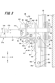
- FIG. 3 is a diagram showing the configuration of a stopper mechanism provided in the elevator according to the embodiment.
- the stopper mechanism 40 includes a stopper pin operating unit 41 and a stopper pin receiving unit 42.
- the stopper pin operating unit 41 includes a stopper pin 43, a support member 44 that supports the stopper pin 43, a first fixed bracket 45, a second fixed bracket 46, a locking member 47, and a cover member 48 (see FIG. 4).
- the stopper pin 43 is provided on the car 11 as an example of a second engaging member.
- the support member 44 is a member that supports the stopper pin 43 to be engaged and disengaged with respect to the engaging member 51.
- the first fixed bracket 45 and the second fixed bracket 46 are elements that constitute a fixed member.
- the fixed member is a member that is connected to the support member 44 and is fixed to both the upper frame 31 and the vertical frame 33.
- the configuration of the stopper pin operating unit 41 will be described in detail later.
- the stopper pin receiving portion 42 is provided with an engagement member 51.
- the engagement member 51 is provided on the guide rail 30 as an example of a first engagement member.
- the engagement member 51 is fixed to the guide rail 30.
- the engagement member 51 is provided with a through hole 52.
- the through hole 52 is a hole into which the stopper pin 43 is inserted when the car 11 is fixed to the guide rail 30 by the stopper mechanism 40.
- the stopper pin 43 is a pin with a circular cross section (round pin), and the through hole 52 is a circular hole corresponding to the cross-sectional shape of the stopper pin 43.
- the engagement member 51 is fixed to the guide rail 30 by a bolt and nut mechanism 53.
- the bolt and nut mechanism is a mechanism that fastens and fixes members to each other using a bolt and a nut.
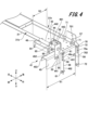
- FIGS. Fig. 4 is a perspective view showing the arrangement of the stopper pin operating unit
- Fig. 5 is a perspective view showing the support structure of the stopper pin
- Fig. 6 is a plan view showing the support structure of the stopper pin
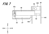
- Fig. 7 is a front view showing the support structure of the stopper pin
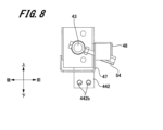
- Fig. 8 is a left side view showing the support structure of the stopper pin
- Fig. 9 is a right side view showing the support structure of the stopper pin. Note that in Fig. 4, the notation of the vertical frame is omitted, and part of the bolt and nut mechanism that fixes the members together is omitted.
- the stopper pin 43 is supported by both the upper frame 31 and the vertical frame 33 by a support member 44, a first fixed bracket 45, and a second fixed bracket 46. As shown in FIG. 3, one end of the stopper pin 43 is inserted into the through hole 52 of the engagement member 51 when performing maintenance and inspection work on the hoist 12. This causes the stopper pin 43 and the engagement member 51 to engage with each other.
- a locking bar 54 is attached near the other end of the stopper pin 43. The locking bar 54 is positioned so that it protrudes radially outward from the outer circumferential surface of the stopper pin 43.
- the support member 44 supports the stopper pin 43 so that it can move in the left-right direction.
- the support member 44 also supports the stopper pin 43 so that it can rotate around the central axis of the stopper pin 43.
- the support member 44 is an integral structure having a pair of support pieces 441, 442 that face each other in the left-right direction and a connecting piece 443 that connects the pair of support pieces 441, 442.
- the pair of support pieces 441, 442 are provided with guide holes 441a, 442a, respectively.
- the stopper pin 43 is supported so that it can move and rotate as described above by being inserted into the guide holes 441a, 442a of the support member 44.
- the pair of support pieces 441, 442 are also provided with fixing holes 441b, 442b, respectively.
- the fixing holes 441b, 442b are holes for fixing the support member 44 and the first fixed bracket 45.
- the first fixed bracket 45 is an integral structure having three connecting pieces 451, 452, and 453.
- the connecting piece 451 corresponds to the first connecting piece
- the connecting piece 452 corresponds to the second connecting piece.
- the connecting pieces 451 and 453 are arranged in a state of facing each other in the left-right direction.
- the connecting piece 452 is arranged in a direction that forms a right angle with the connecting pieces 451 and 453.
- the first fixed bracket 45 is bent into a substantially inverted L-shape (substantially inverted J-shape) when viewed from the front-rear direction.
- the width dimension W1 of the first fixed bracket 45 in the front-rear direction is larger than the width dimension W2 of the upper frame 31.
- the first fixed bracket 45 is arranged in a state of supporting the upper frame 31 over the entire width of the upper frame 31.
- one end side of the first fixed bracket 45 in the width direction is arranged to protrude forward from the upper frame 31.
- the first fixing bracket 45 is connected to the upper frame 31, the vertical frame 33, and the support member 44 by three connecting pieces 451, 452, and 453.
- the connecting piece 451 is connected and fixed to the support piece 441 of the support member 44 by a bolt and nut mechanism 55 in the left-right direction corresponding to the first direction.
- the bolt and nut mechanism 55 is disposed in a position shifted forward from the upper frame 31.
- the bolt and nut mechanism 55 is attached using a fixing hole 441b (see FIG. 5) provided in the support piece 441.
- the connecting piece 451 is connected and fixed to the main surface 33a (see FIG. 3) of the vertical frame 33 in the left-right direction by a bolt and nut mechanism 56.
- the main surface 33a of the vertical frame 33 corresponds to the first surface of the vertical frame 33.
- the bolt and nut mechanism 56 is disposed within the range of the width dimension W2 of the upper frame 31.
- the connection piece 452 is connected and fixed to the main surface (lower surface) 31a of the upper frame 31 by a bolt and nut mechanism 57 in the up-down direction corresponding to the second direction.
- the main surface 31a of the upper frame 31 corresponds to the first surface of the upper frame 31.
- the bolt and nut mechanism 57 is arranged within the range of the width dimension W2 of the upper frame 31.
- the connection piece 453 is connected and fixed to the support piece 442 of the support member 44 in the left-right direction by a bolt and nut mechanism 58.
- the bolt and nut mechanism 58 is attached using a fixing hole 442b (see FIG. 5) provided in the support piece 442.
- the bolt and nut mechanism 58 is arranged coaxially with the bolt and nut mechanism 55 described above.
- the second fixing bracket 46 is an integral structure having two connecting pieces 461, 462.
- the second fixing bracket 46 is formed in a flat plate shape.
- the connecting piece 461 corresponds to the third connecting piece
- the connecting piece 462 corresponds to the fourth connecting piece.
- the second fixing bracket 46 is connected to the upper frame 31, the vertical frame 33, and the support member 44 by the two connecting pieces 461, 462.
- the connecting piece 461 is connected and fixed to the connecting piece 443 of the support member 44 in the front-rear direction, which corresponds to the third direction, by a bolt and nut mechanism (not shown). This bolt and nut mechanism is attached using the fixing holes 59 provided in the connecting piece 461 and the connecting piece 443.
- the connecting piece 461 is connected and fixed to the side surface 31b of the upper frame 31 in the front-rear direction by a bolt and nut mechanism 60 (see FIG. 3).
- the side surface 31b of the upper frame 31 corresponds to the second surface of the upper frame 31.
- the connecting piece 462 is connected and fixed to the side surface 33b of the vertical frame 33 in the front-rear direction by a bolt and nut mechanism 61.
- the side surface 33b of the vertical frame 33 corresponds to the second surface of the vertical frame 33.
- the locking member 47 is connected and fixed to the support piece 442 of the support member 44 in the left-right direction by a bolt and nut mechanism 65.
- the locking member 47 is provided with two locking grooves 47a, 47b.
- the two locking grooves 47a, 47b are formed at a predetermined distance apart in the left-right direction.
- Each of the locking grooves 47a, 47b is formed in an approximately U-shape when viewed from the front-rear direction.
- the locking bar 54 attached to the stopper pin 43 is locked to the locking groove 47a or the locking groove 47b.
- the locking groove 47a is a groove for holding the stopper pin 43 in the engagement position
- the locking groove 47b is a groove for holding the stopper pin 43 in the retracted position.
- the engagement position is the position where the stopper pin 43 engages with the engagement member 51 as shown in FIG. 3
- the retracted position is the position where the stopper pin 43 retracts (retreats) from the engagement position.
- Cover member 48 is a member that protects switches, wiring, etc. (not shown).
- locking member 47 is detachably attached to locking member 47.
- locking bar 54 interferes with (comes into) cover member 48, restricting the range of rotation of stopper pin 43. For this reason, if an operator wants to operate stopper pin 43 by holding locking bar 54 with his/her fingers, cover member 48 must be removed.
- the elevator 10 is equipped with a connecting bracket 70 (see FIG. 4) that connects the upper frame 31 and the vertical frame 33.
- the connecting brackets 70 are arranged symmetrically on the left and right sides of the car 11, similar to the stopper mechanism 40 described above.
- the connecting bracket 70 is an integral structure having two connecting pieces 701, 702.
- the connecting bracket 70 is connected to the upper frame 31 and the vertical frame 33 by the two connecting pieces 701, 702.
- the connecting piece 701 is connected and fixed to the side surface 31b of the upper frame 31 in the front-rear direction by a bolt and nut mechanism 71.
- the connecting piece 702 is connected and fixed to the side surface 33b of the vertical frame 33 in the front-rear direction by a bolt and nut mechanism 72.
- the connecting bracket 70 is arranged facing the second fixed bracket 46 in the front-to-rear direction with the upper frame 31 in between.
- the connecting bracket 70 has the same structure as the second fixed bracket 46 described above.
- a long hole 70a is provided in the connecting bracket 70, and a long hole 46a is also provided in the second fixed bracket 46.
- the long holes 46a, 70a correspond to position adjustment parts for shifting the position of the upper frame 31 relative to the vertical frame 33 upward from a reference position.
- the reference position is the position where the upper frame 31 is finally attached during the assembly process of the car 11.
- the upper bolt and nut mechanisms 61, 72 are loosened and the lower bolt and nut mechanisms 61, 72 are removed, allowing the upper frame 31 to be moved in the longitudinal direction (up and down) of the long holes 46a, 70a.
- the car frame 25 is assembled and then the ceiling 29 and side panels 28 are attached.
- the ceiling 29 is fastened inside the car frame 25 and near the upper frame 31, and the side panels 28 are attached in this state; however, if the upper frame 31 is left in the reference position, the ceiling 29 will interfere with the side panels 28, making it difficult to attach the side panels 28.
- the side plates 28 can be attached while avoiding interference with the ceiling 29, and then the ceiling 29 can be attached to the side plates 28. Also, after the side plates 28 and the ceiling 29 are attached to the inside of the car frame 25, the bolt and nut mechanisms 61, 72 can be loosened to position the upper frame 31 at the reference position, and the upper and lower bolt and nut mechanisms 61, 72 can be tightened to fix the upper frame 31 at the reference position.
- a worker 21 performing maintenance and inspection work on the hoist 12 operates the stopper mechanism 40 so that the car 11 is not pulled by the counterweight 14 and rises even when the brake on the hoist 12 is released. Specifically, before releasing the brake, the worker 21 pinches the locking bar 54 with his fingers and rotates and moves the stopper pin 43 as appropriate, thereby switching the position into which the locking bar 54 fits from the locking groove 47b to the locking groove 47a. This results in a state in which the stopper pin 43 is inserted into the through hole 52 of the engagement member 51, i.e., the stopper pin 43 and the engagement member 51 are engaged. When the worker 21 releases the brake on the hoist 12 in this state, the tensile load of the counterweight 14 is applied to the car 11.
- the stopper pin 43 is supported by both the upper frame 31 and the vertical frame 33 via the support member 44, the first fixed bracket 45, and the second fixed bracket 46. Therefore, the tensile load by the counterweight 14 is distributed and applied to the upper frame 31 and the vertical frame 33. In other words, the tensile load by the counterweight 14 can be supported by both the upper frame 31 and the vertical frame 33. Therefore, the deformation of the upper frame 31 can be suppressed compared to the case where the stopper pin 43 is supported only by the upper frame 31. Therefore, when the car 11 is fixed to the guide rail 30 by the stopper mechanism 40, the car 11 can withstand the tensile load by the counterweight 14 without increasing the vertical cross-sectional dimension of the upper frame 31.
- the vertical cross-sectional dimension of the upper frame 31 can be the same between the elevator 10 equipped with the stopper mechanism 40 and the elevator not equipped with the stopper mechanism 40, thereby enabling the parts to be shared.
- the stopper mechanism 40 has a support member 44 that supports the stopper pin 43 so that it can be engaged and disengaged with respect to the engagement member 51, and fixing members (45, 46) that are connected to the support member 44 and are fixed to both the upper frame 31 and the vertical frame 33. This allows the tensile load from the counterweight 14 to be transmitted to the upper frame 31 and the vertical frame 33 via the support member 44 and the fixing members (45, 46).
- the fixing member has a first fixing bracket 45 fixed to the main surface 31a of the upper frame 31 and the main surface 33a of the vertical frame 33, and a second fixing bracket 46 fixed to the side surface 31b of the upper frame 31 and the side surface 33b of the vertical frame 33.
- This allows the tensile load from the counterweight 14 to be distributed in a well-balanced manner to the upper frame 31 and the vertical frame 33, compared to when the fixing member is composed of a single part.
- the first fixing bracket 45 and the second fixing bracket 46 are fixed to different surfaces of the upper frame 31 and the vertical frame 33, respectively, it is possible to avoid concentration of the tensile load on a specific surface.
- the first fixed bracket 45 has a connection piece 451 that is connected to the support member 44 and the vertical frame 33 in the left-right direction and a connection piece 452 that is connected to the upper frame 31 in the up-down direction
- the second fixed bracket 46 has a connection piece 461 that is connected to the support member 44 and the upper frame 31 in the front-to-back direction and a connection piece 462 that is connected to the vertical frame 33 in the front-to-back direction.
- the first fixed bracket 45 is positioned in a state in which it supports the upper frame 31. This increases the connection strength between the upper frame 31 and the vertical frame 33.
- a connecting bracket 70 is disposed at a position facing the second fixed bracket 46 in the front-rear direction, and this connecting bracket 70 connects the upper frame 31 and the vertical frame 33. This allows both ends of the upper frame 31 in the width direction to be connected to the vertical frame 33 in a well-balanced manner by the second fixed bracket 46 and the connecting bracket 70.
- the connecting bracket 70 has the same structure as the second fixed bracket 46. This allows for the sharing of parts.
- the connecting bracket 70 and the second fixed bracket 46 have long holes 70a, 46a, respectively. This allows the side panel 28 to be attached without interfering with the ceiling 29 during the assembly process of the car 11. Furthermore, the connecting bracket 70 and the second fixed bracket 46 can be given two functions, specifically, the function of connecting the upper frame 31 and the vertical frame 33, and the function of temporarily shifting the position of the upper frame 31 upward.
- the present invention is not limited to the above-described embodiment, but includes various modified examples.
- the above-described embodiment has been described in detail to make the contents of the present invention easy to understand, but the present invention is not necessarily limited to having all the configurations described in the above-described embodiment.
- a configuration is adopted in which a stopper pin receiving portion 42 having an engaging member 51 is provided on the guide rail 30, and a stopper pin operating portion 41 having a stopper pin 43 is provided on the car 11.
- the present invention is not limited to the configuration of the above embodiment, and for example, a configuration may be adopted in which a stopper pin receiving portion 42 having an engaging member 51 is provided on the car 11, and a stopper pin operating portion 41 having a stopper pin 43 is provided on the guide rail 30.
- the long holes 46a, 70a are given as an example of the position adjustment parts provided in the second fixed bracket 46 and the connecting bracket 70, but the present invention is not limited to this.
- the position adjustment parts may be configured with multiple through holes (holes for inserting bolts) lined up in the vertical direction.
Landscapes
- Engineering & Computer Science (AREA)
- Mechanical Engineering (AREA)
- Cage And Drive Apparatuses For Elevators (AREA)
Abstract
Description
本願は、上記課題を解決する手段を複数含んでいるが、その一つを挙げるならば、上枠及び縦枠を有する乗りかごと、乗りかごの移動を案内するガイドレールと、ガイドレールに設けられた第1係合部材と、乗りかごに設けられた第2係合部材と、を有し、第1係合部材と第2係合部材とを係合させることによりガイドレールに乗りかごを固定するストッパー機構と、を備え、第2係合部材は、上枠及び縦枠の両方に支持されている、エレベーターである。
上記した以外の課題、構成および効果は、以下の実施形態の説明によって明らかにされる。
図1は、実施形態に係るエレベーターの構成を示す概略図である。
図1に示すように、エレベーター10は、建築物の屋上などに機械室を設ける必要がない、いわゆる機械室レスエレベーターである。エレベーター10は、乗りかご11と、巻上機12と、主ロープ13と、釣り合い錘14と、コンペンチェーン15と、を備えている。
図2は、実施形態に係るエレベーターが備える乗りかごの構成を示す斜視図である。
本実施形態においては、エレベーター10の乗場17側から昇降路16内の乗りかご11を見た場合を基準にして、前後・上下・左右の各方向を定義する。この場合、乗場17側から見て手前側が前方向、奥側が後ろ方向、上側が上方向、下側が下方向、左側が左方向、右側が右方向となる。
図3は、実施形態に係るエレベーターが備えるストッパー機構の構成を示す図である。
図3に示すように、ストッパー機構40は、ストッパーピン操作部41と、ストッパーピン受け入れ部42と、を備えている。ストッパーピン操作部41は、ストッパーピン43と、ストッパーピン43を支持する支持部材44と、第1固定ブラケット45と、第2固定ブラケット46と、係止部材47と、カバー部材48(図4参照)と、を備えている。ストッパーピン43は、第2係合部材の一例として乗りかご11に設けられている。支持部材44は、係合部材51に対してストッパーピン43を係合離脱可能に支持する部材である。第1固定ブラケット45及び第2固定ブラケット46は、固定部材を構成する要素である。固定部材は、支持部材44に連結されると共に、上枠31及び縦枠33の両方に固定される部材である。ストッパーピン操作部41の構成については、後段で詳しく説明する。
図4は、ストッパーピン操作部の配置状態を示す斜視図であり、図5は、ストッパーピンの支持構造を示す斜視図である。また、図6は、ストッパーピンの支持構造を示す平面図であり、図7は、ストッパーピンの支持構造を示す正面図であり、図8は、ストッパーピンの支持構造を示す左側面図であり、図9は、ストッパーピンの支持構造を示す右側面図である。なお、図4においては、縦枠の表記を省略するとともに、部材同士を固定するボルト・ナット機構の一部を省略している。
本実施形態において、ストッパーピン43は、支持部材44、第1固定ブラケット45及び第2固定ブラケット46を介して、上枠31及び縦枠33の両方に支持されている。このため、釣り合い錘14による引っ張り荷重は、上枠31と縦枠33に分散して加わる。つまり、釣り合い錘14による引っ張り荷重を、上枠31と縦枠33の両方で受け持つことができる。このため、ストッパーピン43を上枠31のみによって支持する場合に比べて、上枠31の変形を抑制することができる。したがって、ストッパー機構40によってガイドレール30に乗りかご11を固定する場合に、乗りかご11の上枠31の縦断面寸法を大きくしなくても、釣り合い錘14による引っ張り荷重に耐えることができる。その結果、かご枠25の高さ寸法や昇降路16のオーバーヘッド寸法を小さくすることが可能となる。また、ストッパー機構40を備えるエレベーター10と、ストッパー機構40を備えないエレベーターで、上枠31の縦断面寸法を同じ寸法にして部品の共用化を図ることができる。
なお、本発明は、上述した実施形態に限定されるものではなく、様々な変形例を含む。例えば、上述した実施形態では、本発明の内容を理解しやすいように詳細に説明しているが、本発明は、上述した実施形態で説明したすべての構成を必ずしも備えるものに限定されない。また、ある実施形態の構成の一部を、他の実施形態の構成に置き換えることが可能である。また、ある実施形態の構成に他の実施形態の構成を加えることも可能である。また、各実施形態の構成の一部について、これを削除し、または他の構成を追加し、あるいは他の構成に置換することも可能である。
Claims (8)
- 上枠及び縦枠を有する乗りかごと、
前記乗りかごの移動を案内するガイドレールと、
前記ガイドレールに設けられた第1係合部材と、前記乗りかごに設けられた第2係合部材と、を有し、前記第1係合部材と前記第2係合部材とを係合させることにより前記ガイドレールに前記乗りかごを固定するストッパー機構と、を備え、
前記第2係合部材は、前記上枠及び前記縦枠の両方に支持されている
エレベーター。 - 前記ストッパー機構は、前記第1係合部材に対して前記第2係合部材を係合離脱可能に支持する支持部材と、前記支持部材に連結されると共に、前記上枠及び前記縦枠の両方に固定される固定部材と、をさらに有する
請求項1に記載のエレベーター。 - 前記固定部材は、前記上枠の第1面と前記縦枠の第1面に固定される第1固定ブラケットと、前記上枠の第2面と前記縦枠の第2面に固定される第2固定ブラケットと、を有する
請求項2に記載のエレベーター。 - 前記第1固定ブラケットは、第1の方向で前記支持部材及び前記縦枠に接続される第1の接続片と、前記第1の方向と直角をなす第2の方向で前記上枠に接続される第2の接続片と、を有し、
前記第2固定ブラケットは、前記第1の方向及び前記第2の方向と直角をなす第3の方向で前記支持部材及び前記上枠に接続される第3の接続片と、前記第3の方向で前記縦枠に接続される第4の接続片と、を有する
請求項3に記載のエレベーター。 - 前記第1固定ブラケットは、前記上枠を担持する状態で配置されている
請求項3に記載のエレベーター。 - 前記第3の方向で前記第2固定ブラケットと対向する位置に配置され、前記上枠と前記縦枠とを連結する連結ブラケットをさらに備える
請求項4に記載のエレベーター。 - 前記連結ブラケットは、前記第2固定ブラケットと同じ構造を有する
請求項6に記載のエレベーター。 - 前記連結ブラケットと前記第2固定ブラケットは、前記縦枠に対する前記上枠の位置を基準位置よりも上方向にずらしておくための位置調整部を有する
請求項6に記載のエレベーター。
Priority Applications (3)
| Application Number | Priority Date | Filing Date | Title |
|---|---|---|---|
| PCT/JP2023/001252 WO2024154239A1 (ja) | 2023-01-18 | 2023-01-18 | エレベーター |
| JP2024571486A JPWO2024154239A1 (ja) | 2023-01-18 | 2023-01-18 | |
| CN202380083123.3A CN120379918A (zh) | 2023-01-18 | 2023-01-18 | 电梯 |
Applications Claiming Priority (1)
| Application Number | Priority Date | Filing Date | Title |
|---|---|---|---|
| PCT/JP2023/001252 WO2024154239A1 (ja) | 2023-01-18 | 2023-01-18 | エレベーター |
Publications (1)
| Publication Number | Publication Date |
|---|---|
| WO2024154239A1 true WO2024154239A1 (ja) | 2024-07-25 |
Family
ID=91955564
Family Applications (1)
| Application Number | Title | Priority Date | Filing Date |
|---|---|---|---|
| PCT/JP2023/001252 Ceased WO2024154239A1 (ja) | 2023-01-18 | 2023-01-18 | エレベーター |
Country Status (3)
| Country | Link |
|---|---|
| JP (1) | JPWO2024154239A1 (ja) |
| CN (1) | CN120379918A (ja) |
| WO (1) | WO2024154239A1 (ja) |
Citations (5)
| Publication number | Priority date | Publication date | Assignee | Title |
|---|---|---|---|---|
| JP2000203774A (ja) * | 1998-11-12 | 2000-07-25 | Toshiba Corp | エレベ―タ籠の停止ロック装置 |
| WO2006129346A1 (ja) * | 2005-05-31 | 2006-12-07 | Mitsubishi Denki Kabushiki Kaisha | エレベータ装置 |
| JP2007246212A (ja) * | 2006-03-15 | 2007-09-27 | Hitachi Building Systems Co Ltd | エレベーターの乗りかご固定装置 |
| JP2014061968A (ja) * | 2012-09-20 | 2014-04-10 | Fujitec Co Ltd | エレベータの固定装置 |
| CN213802433U (zh) * | 2020-06-11 | 2021-07-27 | 广东联合富士电梯有限公司 | 一种无机房电梯锁梯装置 |
-
2023
- 2023-01-18 WO PCT/JP2023/001252 patent/WO2024154239A1/ja not_active Ceased
- 2023-01-18 JP JP2024571486A patent/JPWO2024154239A1/ja active Pending
- 2023-01-18 CN CN202380083123.3A patent/CN120379918A/zh active Pending
Patent Citations (5)
| Publication number | Priority date | Publication date | Assignee | Title |
|---|---|---|---|---|
| JP2000203774A (ja) * | 1998-11-12 | 2000-07-25 | Toshiba Corp | エレベ―タ籠の停止ロック装置 |
| WO2006129346A1 (ja) * | 2005-05-31 | 2006-12-07 | Mitsubishi Denki Kabushiki Kaisha | エレベータ装置 |
| JP2007246212A (ja) * | 2006-03-15 | 2007-09-27 | Hitachi Building Systems Co Ltd | エレベーターの乗りかご固定装置 |
| JP2014061968A (ja) * | 2012-09-20 | 2014-04-10 | Fujitec Co Ltd | エレベータの固定装置 |
| CN213802433U (zh) * | 2020-06-11 | 2021-07-27 | 广东联合富士电梯有限公司 | 一种无机房电梯锁梯装置 |
Also Published As
| Publication number | Publication date |
|---|---|
| CN120379918A (zh) | 2025-07-25 |
| JPWO2024154239A1 (ja) | 2024-07-25 |
Similar Documents
| Publication | Publication Date | Title |
|---|---|---|
| US7293631B2 (en) | Machine room-less elevator | |
| US20040168861A1 (en) | Elevator device | |
| EP1405813A1 (en) | Elevator device | |
| US8172041B2 (en) | Machine room-less elevator | |
| CN100402402C (zh) | 电梯 | |
| US7562745B2 (en) | Elevator with an operation space in a center of a machine room | |
| JP6738964B2 (ja) | エレベーター | |
| JP2012056773A (ja) | 機械室レスエレベータ | |
| WO2024154239A1 (ja) | エレベーター | |
| JP6432926B1 (ja) | エレベータ装置 | |
| JP3603606B2 (ja) | エレベータ装置 | |
| WO2016166882A1 (ja) | 機械室レスエレベータ | |
| JPH1081463A (ja) | サイドフォーク型エレベーター | |
| JP2006264862A (ja) | マシンルームレスエレベータ | |
| JP2002179356A (ja) | エレベータ | |
| JP2013122145A (ja) | エレベータのドアロック機構 | |
| WO2004050528A1 (ja) | エレベータ装置 | |
| JP2002068641A (ja) | エレベーター装置 | |
| TW202308931A (zh) | 搭乘用梯箱及電梯 | |
| JP7224532B2 (ja) | エレベータのピット梯子装置 | |
| JP2011051736A (ja) | エレベータ装置 | |
| JP4825475B2 (ja) | エレベータのかご上シーブカバー支持構造 | |
| JP7822991B2 (ja) | 乗りかご、エレベーター及びドア開閉装置 | |
| JP6223234B2 (ja) | エレベータ装置 | |
| JPWO2002022487A1 (ja) | エレベータ装置 |
Legal Events
| Date | Code | Title | Description |
|---|---|---|---|
| 121 | Ep: the epo has been informed by wipo that ep was designated in this application |
Ref document number: 23917453 Country of ref document: EP Kind code of ref document: A1 |
|
| WWE | Wipo information: entry into national phase |
Ref document number: 2024571486 Country of ref document: JP |
|
| WWE | Wipo information: entry into national phase |
Ref document number: 202380083123.3 Country of ref document: CN |
|
| WWE | Wipo information: entry into national phase |
Ref document number: 202517054934 Country of ref document: IN |
|
| WWP | Wipo information: published in national office |
Ref document number: 202517054934 Country of ref document: IN |
|
| WWP | Wipo information: published in national office |
Ref document number: 202380083123.3 Country of ref document: CN |
|
| NENP | Non-entry into the national phase |
Ref country code: DE |
|
| 122 | Ep: pct application non-entry in european phase |
Ref document number: 23917453 Country of ref document: EP Kind code of ref document: A1 |