WO2024154220A1 - 除湿機 - Google Patents
除湿機 Download PDFInfo
- Publication number
- WO2024154220A1 WO2024154220A1 PCT/JP2023/001150 JP2023001150W WO2024154220A1 WO 2024154220 A1 WO2024154220 A1 WO 2024154220A1 JP 2023001150 W JP2023001150 W JP 2023001150W WO 2024154220 A1 WO2024154220 A1 WO 2024154220A1
- Authority
- WO
- WIPO (PCT)
- Prior art keywords
- dehumidifier
- reactor
- air
- housing
- substrate
- Prior art date
- Legal status (The legal status is an assumption and is not a legal conclusion. Google has not performed a legal analysis and makes no representation as to the accuracy of the status listed.)
- Ceased
Links
Images


Classifications
-
- F—MECHANICAL ENGINEERING; LIGHTING; HEATING; WEAPONS; BLASTING
- F24—HEATING; RANGES; VENTILATING
- F24F—AIR-CONDITIONING; AIR-HUMIDIFICATION; VENTILATION; USE OF AIR CURRENTS FOR SCREENING
- F24F2130/00—Control inputs relating to environmental factors not covered by group F24F2110/00
- F24F2130/20—Sunlight
Definitions
- This disclosure relates to a dehumidifier.
- Patent Document 1 describes a dehumidifier.
- the purpose of this dehumidifier is to prevent heat generated by the control device from building up inside the dehumidifier's housing.
- the dehumidifier shown in Patent Document 1 provides cooling by providing heat dissipation fins on the control device, a cooling fan that blows air toward the heat dissipation fins, and an air passage through which the air from the cooling fan passes.
- the dehumidifier in Patent Document 1 requires a cooling fan and air passage components, resulting in a large number of parts. Also, cooling is performed using only the wind from the cooling fan, resulting in poor efficiency.
- This disclosure has been made to solve the problems described above.
- the purpose of this disclosure is to provide a dehumidifier that can efficiently cool a substrate and a reactor.
- the dehumidifier according to the present disclosure is a dehumidifier comprising a housing with an intake port and an exhaust port, an air supply duct extending from the intake port to the exhaust port, an air blowing means provided within the air supply duct to generate an airflow, a dehumidifying means disposed within the housing to remove moisture from the airflow, and a substrate and a reactor disposed within the housing to control the operation of the air blowing means and the dehumidifying means, a substrate storage space in which the substrate and the reactor are disposed is provided in a cooling air passage connected to the air supply duct, and an opening for taking in air from outside the housing is provided at a position upstream of the cooling air passage in the substrate storage space.
- This disclosure makes it possible to provide a dehumidifier that can efficiently cool the substrate and the reactor.
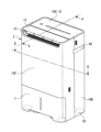
- FIG. 1 is a perspective view of a dehumidifier according to a first embodiment, seen from the front side.
- FIG. 1 is a perspective view of the dehumidifier of the first embodiment as viewed from the rear side.
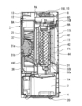
- FIG. 2 is a vertical cross-sectional view taken along line AA shown in FIG. 1.
- 2 is a horizontal cross-sectional view taken along line BB shown in FIG. 1.
- FIG. 2 is a perspective view of a substrate storage space in the first embodiment.
- FIG. 2 is an exploded perspective view of a power supply control box of the dehumidifier according to the first embodiment.
- FIG. 2 is an exploded perspective view of the reactor box of the dehumidifier according to the first embodiment.
- FIG. 9 is a vertical cross-sectional view of a main portion taken along line CC shown in FIG. 8.
- 9 is a vertical cross-sectional view of a main portion taken along line DD shown in FIG. 8.
- 9 is a vertical cross-sectional view of a main part taken along line EE shown in FIG. 8.
- 13 is an oblique view of the arrangement of the power supply control board box and reactor box of the dehumidifier of embodiment 2.
- FIG. FIG. 11 is an exploded perspective view of a reactor box of a dehumidifier according to a third embodiment.
- Fig. 1 is a perspective view of the dehumidifier 1 of the first embodiment as viewed from the front side.
- Fig. 2 is a perspective view of the dehumidifier 1 of the first embodiment as viewed from the rear side.
- Fig. 3 is a vertical cross-sectional view taken along line A-A in Fig. 1.
- Fig. 4 is a horizontal cross-sectional view taken along line B-B in Fig. 1.
- the dehumidifier 1 will be described in principle based on the state in which the dehumidifier 1 is placed on a horizontal surface such as a floor.
- the dehumidifier 1 has a front case 10F and a rear case 10B.
- the front case 10F and the rear case 10B constitute a part of a housing that forms the outer shell of the dehumidifier 1.
- the housing has a bottom plate 4 to which a number of wheels 20, which will be described later, are attached.
- the bottom plate 4 has wheels (casters) 20 for moving the dehumidifier 1, one each at each end, spaced apart from each other. Heavy objects such as an electric compressor (described later) are placed on the bottom plate 4.
- the front case 10F and the rear case 10B are assembled into a single box shape by fastening them with fasteners (not shown) such as screws.
- the front case 10F is a member that forms the front portion of the dehumidifier 1.
- the rear case 10B is a member that forms the rear portion of the dehumidifier 1.
- the flat upper case 10U is connected to the upper ends of the front case 10F and the rear case 10B.
- Louvers 13 (described below) are arranged in front of the upper case 10U, and the upper case 10U and the louvers 13 abut against each other from the front and back, forming a single flat surface. This surface serves as the ceiling surface of the housing.
- a hollow box-shaped housing is formed by the front case 10F, rear case 10B, bottom plate 4, and top case 10U.
- the inside of the hollow housing formed by the front case 10F, rear case 10B, bottom plate 4, and top case 10U is divided into six spaces: the blower fan space BA, the heat exchanger arrangement space HA, the filter arrangement space FA, the water tank arrangement space TA, the board storage space PA, and the compressor arrangement space (not shown).
- the housing is formed with an intake port 11 and an exhaust port 12.
- the intake port 11 is an opening for taking in air from the outside of the dehumidifier 1 into the inside of the dehumidifier 1.
- the exhaust port 12 is an opening for sending air from the inside of the dehumidifier 1 to the outside of the dehumidifier 1.
- the intake port 11 is formed in the shape of a square window in the central portion of the rear case 10B.
- the exhaust port 12 is formed in the ceiling surface portion of the dehumidifier 1. Louvers 13, which will be described later, are arranged in the exhaust port 12, and the louvers 13 are opened upward to a certain angle around an axis (not shown) to open the exhaust port.
- the dehumidifier 1 is equipped with an inlet cover 11A that covers the inlet 11.
- the inlet cover 11A is formed, for example, in a lattice shape. Alternatively, the inlet cover 11A may be a fine shutter (louver shape) all over. This inlet cover 11A prevents foreign matter from entering the inside of the dehumidifier 1 through the inlet 11.
- the inlet cover 11A is fixed, for example, to the rear case 10B in a removable manner.
- the dehumidifier 1 includes an electric compressor (not shown).
- the electric compressor is arranged in a compressor arrangement space (not shown).
- the electric compressor may be of any type, such as a reciprocating type or a rotary type.
- This electric compressor has a motor (not shown) and forcibly circulates refrigerant in a refrigerant pipe (also called a "refrigerant circuit") 22 that is connected to an evaporator 31 and condensers 32a, 32b (described later).
- the electric compressor compresses and supplies refrigerant to a refrigeration cycle formed by connecting the evaporator 31 and condensers 32a, 32b, etc., with the refrigerant pipe 22.
- the electric compressor is controlled by a power supply control board 61.
- the drain water that is generated on the external surface of the evaporator 31 during the dehumidification operation drips directly into the water storage tank 7.
- the water storage tank 7 is placed in the water storage tank arrangement space TA, and can be removed from the dehumidifier 1 through an outlet (not shown) formed in the front case 10F.
- Louver 13 is a single plate-like member that is positioned near air outlet 12. Louver 13 may be composed of several plate-like members. Louver 13 is used to adjust the direction in which air is blown out from air outlet 12, and is positioned so that it can be opened and closed freely.
- the position of the louvers 13 can be changed by a connected louver drive motor (not shown).
- the louver drive motor (not shown) changes the inclination angle of the louvers 13 relative to the air outlet 12 in several stages or more. This makes it possible to adjust the direction of the air blown out from the air outlet 12.
- the dehumidifier 1 is equipped with an operation notification unit 15.
- the operation notification unit 15 is composed of an input operation unit that allows the user to operate the dehumidifier 1, and a notification unit.
- the notification unit displays the status of the dehumidifier 1 to the user using visible information such as text.
- the notification unit can also notify the user by voice.
- An operation display board 8 that controls the operation notification unit 15 is arranged inside the upper case 10U facing the operation notification unit 15.
- An operation switch that starts and stops the operation of the dehumidifier 1 is arranged on the operation display board 8.
- the space below the operation display board 8 is the board storage space PA.
- the power supply control board box 60 and the reactor box 70 are placed in the board storage space PA.
- the configuration of the board storage space PA and the arrangement of the power supply control board box 60 and the reactor box 70 will be described in detail later.
- the dehumidifier 1 is provided with a fan 21 (rotating blades) inside as a means for sending air.
- the fan 21 is an example of a blowing means that takes in air into the dehumidifier 1 and sends the taken-in air to the outside of the dehumidifier 1.
- the fan 21 rotates to generate an airflow that flows from the intake port 11 to the exhaust port 12 in the air supply air path that runs from the intake port 11 to the exhaust port 12.
- the motor 21a is housed inside the dehumidifier 1.
- the motor 21a is a device that rotates the fan 21.
- the fan 21 and the motor 21a are arranged on the front side of the dehumidifier 1.
- the motor 21a is connected to the rotation center of the fan 21 via a rotating shaft 21b that extends horizontally.
- the rotation operation of the motor 21a is controlled by the power supply control board 61. In other words, the start and stop of rotation and the rotation speed of the motor 21a are each controlled by the power supply control board 61.
- the fan 21 is a sirocco fan (multi-blade fan) whose center of rotation is fixed by the rotating shaft 21b.
- the fan 21 draws air from the front into the inside of the fan case 36 (described below) and blows the air out from the air outlet 12.
- the space in which the fan case 36 is located is referred to as the blower fan space BA.
- the dehumidifier 1 includes an evaporator 31, a first condenser 32a, a second condenser 32b, an electric compressor (not shown), and a pressure reducing device (not shown) as an example of a dehumidification means for removing moisture contained in the air.
- the evaporator 31, the first condenser 32a, and the second condenser 32b form a refrigerant circuit together with the electric compressor (not shown) and the pressure reducing device (not shown).
- the evaporator 31, first condenser 32a, second condenser 32b, electric compressor (not shown), and pressure reducing device (not shown) are housed inside the dehumidifier 1.
- the evaporator 31 and condensers 32a, 32b are each installed vertically so as to block the rear side of the bellmouth portion 37 as shown in FIG. 4.
- the electric compressor (not shown) is installed on the bottom plate 4.
- the space housing the evaporator 31 and condensers 32a, 32b is the heat exchanger arrangement space HA. In other words, the heat exchanger arrangement space HA and the blower fan space BA are partitioned and communicate with each other via the bellmouth portion 37.
- the evaporator 31, the electric compressor (not shown), the first condenser 32a, the second condenser 32b, and the pressure reducing device (not shown) are connected in sequence via refrigerant piping (not shown) or the like. Refrigerant from the electric compressor flows in the refrigerant circuit formed by the evaporator 31, the electric compressor, the first condenser 32a, the second condenser 32b, and the pressure reducing device (not shown).
- the evaporator 31, the first condenser 32a, and the second condenser 32b are heat exchangers for exchanging heat between the refrigerant and air.
- the electric compressor (not shown) is a device that compresses the refrigerant.
- the pressure reducing device (not shown) is a device that reduces the pressure of the refrigerant.
- the pressure reducing device (not shown) is, for example, an expansion valve or a capillary tube.
- the dehumidifier 1 also includes a HEPA filter 41 and an activated carbon filter 42, which are air purification filters for purifying the air, as an example of an air purification means for removing dust or odors from the air.
- the HEPA filter 41 and the activated carbon filter 42 are stored inside the rear case 10B.
- the HEPA filter 41 is a filter that captures fine dust particles in the air.
- the activated carbon filter 42 is a filter that removes odors from the air.
- the HEPA filter 41 and the activated carbon filter 42 can be detachably installed inside the rear case 10B.
- the space in which the bypass air duct 43, which will be described later, and the HEPA filter 41 and the activated carbon filter 42 are arranged is referred to as the filter arrangement space FA.
- an airflow duct is formed inside the dehumidifier 1, leading from the intake 11 to the exhaust 12.
- the airflow inside the airflow duct flows in the following order: intake 11, intake cover 11A, HEPA filter 41, activated carbon filter 42, evaporator 31, second condenser 32b, first condenser 32a, and fan 21.
- a series of airflow ducts is formed so that the air entering from the intake 11 passes through the air purifying filters (HEPA filter 41 and activated carbon filter 42) and flows from the heat exchanger (evaporator 31, etc.) to the fan 21.
- the upstream side and downstream side are defined using the airflow flowing through the air passage leading from the intake port 11 to the exhaust port 12.
- the side where the intake port 11 is located relative to the heat exchanger (evaporator 31, etc.) is defined as the upstream side.
- the side where the exhaust port 12 is located relative to the heat exchanger (evaporator 31, etc.) is defined as the downstream side.
- the bypass air duct 43 is an air duct that extends forward from the air intake 11. In other words, it is a narrow passage that extends from the rear to the front.
- the bypass air duct 43 is an air duct sandwiched between the bypass air duct outer wall 43a and the filter case outer wall 43b.
- the gap between the rear end of the bypass air duct outer wall 43a and the rear end of the filter case outer wall 43b is the entrance of the bypass air duct 43.
- the front end of the bypass air duct outer wall 43a contacts the outer peripheral end of the straightening member 38, so that the airflow does not leak to the outside along the way.
- the gap between the front end of the bypass air duct outer wall 43a and the front end of the filter case outer wall 43b is the exit of the bypass air duct 43.
- the air supply air duct leading from the intake 11 to the exhaust 12 is composed of two air ducts: the main air duct 44 and the bypass air duct 43.
- the main air duct (also called the “first air duct”) 44 is an air duct that runs from the intake 11 through the HEPA filter 41 and the activated carbon filter 42 to the straightening member 38.
- the bypass air duct (also called the “second air duct”) 43 is an air duct that runs from the intake 11 to the straightening member 38 without passing through the HEPA filter 41 and the activated carbon filter 42.
- Reference numeral 51 denotes airflow restriction means for restricting the airflow of the bypass air passage 43 by essentially opening and closing the inlet of the bypass air passage 43.
- the airflow restriction means 51 are disposed on the left and right of the intake port 11.
- an example of the airflow restriction means will be described as a shutter 51s.
- the filter arrangement space FA and the heat exchanger arrangement space HA are connected via the straightening member 38.
- an air path runs from the intake 11 through the filter arrangement space FA, the heat exchanger arrangement space HA, and the blower fan space BA before being blown out from the air outlet 12.
- Figure 5 is a perspective view of the board storage space PA in embodiment 1.
- Figure 5 shows the state in which the upper case 10U, the operation display board 8, the power supply control board box 60, and the reactor box 70 have been removed.
- the board storage space PA is a space surrounded by the front case 10F, rear case 10B, front partition plate 80, board storage space bottom plate 81, and upper case 10U.
- the front partition plate 80 also serves as an air duct partition plate having a bellmouth portion 37.
- the front partition plate 80 is a plate that separates the heat exchanger arrangement space HA and the blower fan space BA.
- the board storage space bottom plate 81 separates the heat exchanger arrangement space HA and the board storage space PA.
- the board storage space PA is a space separated from the heat exchanger arrangement space HA and the blower fan space BA.
- An outside air opening 82 is provided on one side of the rear case 10B, connecting the board storage space PA to the outside of the housing.
- a filter (not shown) is placed in the outside air opening 82 to prevent foreign matter from entering.
- the filter is made of nonwoven fabric, but other methods may also be used.
- the bottom plate 81 of the substrate storage space is provided with a communication port 83 that communicates with the heat exchanger arrangement space HA.
- the communication port 83 is provided on the side opposite the rear case 10B where the outside air opening 82 is provided. In other words, the outside air opening 82 and the communication port 83 are provided at both ends of the substrate storage space PA in the longitudinal direction.
- the size of the communication port 83 is approximately the same as or slightly smaller than the bottom area of the reactor box described below.
- the communication port 83 is connected to the heat exchanger arrangement space HA, which is part of the air passage extending from the intake port 11 to the exhaust port 12, so that when the fan 21 rotates, an airflow is generated from the board storage space PA through the communication port 83 to the heat exchanger arrangement space HA.
- the outside air opening 82 of the board storage space PA is connected to the outside of the housing, an airflow is generated in which air outside the housing enters through the outside air opening 82 and flows toward the communication port 83.
- FIG. 6 is an exploded perspective view of the power supply control box 60 of the dehumidifier in embodiment 1.
- the symbol 62 denotes a support.
- the support 62 is made of resin.
- the support 62 is supported from the back by a rear metal cover 63.
- the power supply control board 61 is supported from the back on one side of the support 62.
- the power supply control board 61 controls the operation of the motor 21a of the fan 21 and the operation of the compressor.
- the power supply control board 61 has an inverter 61a that controls the operation of the compressor.
- a power plug (not shown), a reactor 71, an operation display board 8, a compressor, a motor 21a, etc. are connected to the power supply control board 61.
- the power supply control board 61 When the power plug is connected to an AC power source, an AC voltage is supplied to the power supply control board 61.
- the power supply control board 61 has, for example, a converter circuit formed thereon.
- the converter circuit converts the AC voltage supplied from the AC power source into a DC voltage.
- the reactor 71 boosts the DC voltage.
- the inverter 61a of the power supply control board 61 converts the DC voltage output by the converter circuit into an AC voltage.
- the inverter 61a supplies the AC voltage to the compressor and the motor 21a, etc.
- the inverter 61a changes the frequency of the AC voltage supplied to the compressor and the motor 21a, etc. in multiple stages based on signals from, for example, the operation notification unit 15 and a humidity sensor (not shown), etc.
- the compressor is driven by the AC voltage supplied from the inverter 61a.
- the output of the compressor changes in multiple stages according to the frequency of the AC voltage supplied.
- the power supply control board 61 equipped with the inverter 61a variably controls the output of the compressor.
- the power supply control board 61 has heat dissipation fins 69 for cooling the inverter 61a.
- the heat dissipation fins 69 are supported on the back side of the power supply control board 61.
- the heat dissipation fins 69 are in contact with the IPM (switching element) and other components of the inverter 61a.
- the heat dissipation fins 69 have multiple plates 69a.
- the multiple plates 69a are made of metal.
- the multiple plates 69a are lined up horizontally with their perpendicular lines pointing upward. Adjacent plates 69a have spaces 69b that connect them horizontally.
- the openings between the heat dissipation fins 69 are provided along the flow direction from upstream to downstream of the cooling air duct F. This promotes heat exchange between the airflow flowing through the cooling air duct F and the heat dissipation fins 69.
- the front side of the power supply control board 61 is covered by a first front sheet metal cover 64 and a second front sheet metal cover 65.
- the multiple plates 69a of the heat dissipation fins 69 protrude from openings 65a formed in the second front sheet metal cover 65 when the front side of the power supply control board 61 is covered by the second front sheet metal cover 65.
- the power supply control board 61 is covered by the board cover except for the heat dissipation fins 69. This makes it possible to prevent the adhesion of foreign matter.
- the insulating frame 66 is made of resin.
- the insulating frame 66 is arranged to surround the heat dissipation fins 69.
- the insulating frame 66 is sandwiched between the second front metal cover 65 and the power supply control board 61.
- the insulating frame 66 prevents direct contact between the second front metal cover 65 and the power supply control board 61.
- a temperature detection device (not shown) is attached to the heat dissipation fins 69 to detect the temperature of the heat dissipation fins 69. If an abnormal temperature occurs, the compressor rotation speed is controlled, for example, by reducing it.
- the first front sheet metal cover 64 covers approximately half the area of the front side of the power supply control board 61. Tall components are placed on the board in the area covered by the first front sheet metal cover 64. Low components, other than the heat dissipation fins 69, are placed on the board in the area covered by the second front sheet metal cover 65. As a result, when the sheet metal covers are attached to the power supply control board 61, the height of the first front sheet metal cover 64 is higher than that of the second front sheet metal cover 65.
- the power supply control board 61 is supported from the back side by a support 62, and the support 62 is covered by a back side sheet metal cover 63.
- the front side of the power supply control board 61 is covered by a first front side sheet metal cover 64 and a second front side sheet metal cover 65, and only the multiple plates 69a of the heat dissipation fins 69 are exposed from the second front side sheet metal cover 65. This state is called the power supply control board box 60.
- FIG. 7 is an exploded perspective view of the reactor box 70 of the dehumidifier 1 in the first embodiment.
- the reactor 71 is held by the lower cover 72.
- the top of the reactor 71 is covered by the upper cover 73.
- the lower cover 72 and the upper cover 73 are formed, for example, from a material that is waterproof, fireproof, and has high heat dissipation properties.
- the lower cover 72 and the upper cover 73 are formed, for example, from aluminum.
- the reactor 71 covered by the lower cover 72 and the upper cover 73 is called the reactor box 70.
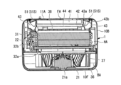
- Figure 8 is a perspective view showing the arrangement of the power supply control board box 60 and reactor box 70 of the dehumidifier 1 of embodiment 1.
- Figure 8 shows the state in which the upper case 10U has been removed together with the operation display board 8.
- Figure 9 is a vertical cross-sectional view of the essential parts taken along line C-C shown in Figure 8.
- Figure 10 is a vertical cross-sectional view of the essential parts taken along line D-D shown in Figure 8.
- Figures 9 and 10 show the state in which the upper case 10U has been attached together with the operation display board 8.
- the power supply control board box 60 and the reactor box 70 are placed in the board storage space PA.
- the power supply control board box 60 is placed in the board storage space PA so that the first front metal cover 64 is on the rear side of the main body of the dehumidifier 1.
- the power supply control board box 60 is placed close to the outside air opening 82. With the power supply control board box 60 in place, the position of the outside air opening 82 is higher than the height of the second front metal cover 65 and is not completely blocked by the first front metal cover 64.
- the reactor box 70 is positioned so as to cover the communication opening 83 in the bottom plate 81 of the substrate storage space. At this time, a space is provided between the communication opening 83 and the lower cover 72 that constitutes the reactor box 70.
- the substrate storage space PA is positioned at the top of the housing, and the ventilation air passage and the cooling air passage F are in communication with each other via the communication opening 83 that is perpendicular to the horizontal plane. This improves cooling efficiency.
- the cooling of the power supply control board box 60 and the reactor box 70 in the board storage space PA will be described.
- the motor 21a connected to the fan 21 and the compressor start to operate.
- the temperatures of the inverter 61a of the power supply control board 61 that controls the compressor and the reactor 71 start to rise.
- the board storage space PA and the ventilation air duct are connected via the communication port 83, so when the fan 21 rotates, an airflow is generated in the board storage space PA from the outside air opening 82 toward the communication port 83.
- the space surrounded by the front partition plate 80, the first front metal cover 64, the second front metal cover 65, and the upper case 10U (operation display board 8) is the cooling air duct F.
- the outside air opening 82 side is the upstream side
- the communication port 83 side is the downstream side.
- the heat dissipation fins 69 are positioned upstream of the reactor box 70.
- the cooling air duct F forms an air duct that travels in a generally straight line from the outside air opening 82 toward the reactor box 70.
- Heat dissipation fins 69 are exposed in the cooling air duct F, and the inverter 61a of the power supply control board 61 is cooled by air passing through the spaces 69b between the multiple plates 69a of the heat dissipation fins 69. Since the air passing through the heat dissipation fins 69 is air that flows in from outside the dehumidifier 1, it is at a lower temperature than the air circulating inside the main body of the dehumidifier 1. This allows for efficient cooling.
- the air that passes through the heat dissipation fins 69 absorbs heat from the fins 69 and increases in temperature.
- the reactor box 70 is located downstream of the heat dissipation fins 69.
- the air that passes through the heat dissipation fins 69 flows through the cooling air duct F and travels straight toward the reactor box 70.
- the reactor box 70 is higher than the second front sheet metal cover 65, and the air that travels straight collides with the reactor box 70.
- the colliding air is dispersed up, down, left, and right along the reactor box 70.
- the air that has been dispersed up, down, left, and right is sucked into the communication port 83 below the reactor box 70, as shown by the arrows in Figure 10. This allows the air to be directed at multiple sides of the reactor box 70, enabling efficient cooling.
- the power supply control board box 60 and the reactor box 70 are arranged in this order from the upstream side of the cooling air duct F, but since the power supply control board box 60, which generates less heat, is arranged upstream, the cooling efficiency is improved.
- the warm air sucked in from the communication port 83 flows into the heat exchanger arrangement space HA. The air is then collected in the air supply duct and blown out from the air outlet 12.
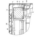
- Figure 11 is a vertical cross-sectional view of the main parts taken along line E-E shown in Figure 8.
- the handle 90 is a recess recessed inward from the surface of the rear case 10B, which is the housing of the dehumidifier 1.
- the reactor box 70 is positioned adjacent to and above the handle 90 inside the housing. This allows the load of the reactor box 70, including the reactor 71, which is a heavy object, to be supported by the upper surface of the handle 90.
- the end of the substrate storage space bottom plate 81 is placed on the upper surface of the inwardly recessed handle portion 90 as a support. Furthermore, the reactor box 70 is fixed to the upper surface of the substrate storage space bottom plate 81 with screws, and the load of the reactor box 70 is supported by the upper surface of the handle portion 90 via the substrate storage space bottom plate 81. Since the handle portion 90 has a roughly box-like shape, it is strong against loads from above and can support the load of the reactor box 70 with minimal reinforcement. It is sufficient that the handle portion 90 supports at least a portion of the load of the reactor box 70.
- the load of the reactor 71 is located near the handle, so the load moment on the handle 90 is small and the inclination of the main body of the dehumidifier 1 is also small, making it possible to move it safely.
- the compressor (not shown) is a heavy object similar to the reactor 71.
- the reactor 71 and the compressor may be disposed on opposite sides of each other in the left-right direction.
- the reactor 71 is disposed near the left side of the housing of the dehumidifier 1.
- the compressor is disposed near the right side of the housing of the dehumidifier 1. This makes the weight balance between the left and right more equal when the dehumidifier 1 is lifted by placing hands on the handle 90. This makes it possible to move the dehumidifier even more safely.
- Fig. 12 is a perspective view showing the arrangement of the power supply control board box 60 and the reactor box 70 of the dehumidifier 1 of the second embodiment.
- a cooling fan 85 is provided upstream of the heat dissipation fins 69 of the power supply control board box 60 placed in the board storage space PA shown in the first embodiment.
- a hood 86 covers the heat dissipation fins 69 and the cooling fan 85.
- the hood 86 has an inlet 86a and an outlet 86b.
- the inlet 86a of the hood 86 is on the upstream side of the cooling air passage F, and the outlet 86b of the hood 86 is on the downstream side of the cooling air passage F.
- the hood 86 is supported from the back side on one side of the second front sheet metal cover 65.
- the hood 86 is made of resin.
- the cooling fan 85 is supported inside the hood 86, on the side of the inlet 86a of the hood 86.
- the cooling fan 85 is an axial fan.
- the cooling fan 85 is connected to the power supply control board 61.
- the cooling fan 85 rotates at a speed according to a control command from the power supply control board 61, and generates an airflow from the inlet 86a to the outlet 86b of the hood 86.
- the airflow generated by the cooling fan 85 cools the heat dissipation fins 69.
- the dehumidifier 1 is characterized by the addition of a hood 86 that covers the heat dissipation fins 69 and a cooling fan 85 provided upstream of the heat dissipation fins 69 in addition to the features of the first embodiment.
- Fig. 13 is an exploded perspective view of the reactor box 70 of the dehumidifier 1 of the third embodiment.
- the lower cover 72 of the reactor box 70 has an opening 72a.
- the upper cover 73 of the reactor box 70 has an opening 73a.
- the opening of the upper cover 73 faces the upstream side of the cooling air duct F.
- the size of each opening 72a and opening 73a is preferably about 5 mm2 in opening area.
- a plurality of openings 72a and openings 73a are provided. Since the reactor cover also has the purpose of fire prevention, the openings are set to about 5 mm2 so that flames will not come out.
- the openings in the cover only need to be opened at least in the positions mentioned above, and additional openings may be opened in other positions.
- the dehumidifier 1 according to the third embodiment of the present disclosure is characterized in that, in addition to the features of the first embodiment, the reactor cover has an opening. Furthermore, the opening of the reactor cover is characterized in that it is provided at least in the direction of the upstream side of the cooling air duct F and in the direction of the communication port 83.
- this embodiment makes it possible to cool the reactor more efficiently by operating the main body of the dehumidifier 1.
Landscapes
- Drying Of Gases (AREA)
Priority Applications (3)
| Application Number | Priority Date | Filing Date | Title |
|---|---|---|---|
| PCT/JP2023/001150 WO2024154220A1 (ja) | 2023-01-17 | 2023-01-17 | 除湿機 |
| JP2024571471A JPWO2024154220A1 (https=) | 2023-01-17 | 2023-01-17 | |
| TW112139677A TWI913592B (zh) | 2023-01-17 | 2023-10-17 | 除濕機 |
Applications Claiming Priority (1)
| Application Number | Priority Date | Filing Date | Title |
|---|---|---|---|
| PCT/JP2023/001150 WO2024154220A1 (ja) | 2023-01-17 | 2023-01-17 | 除湿機 |
Publications (1)
| Publication Number | Publication Date |
|---|---|
| WO2024154220A1 true WO2024154220A1 (ja) | 2024-07-25 |
Family
ID=91955514
Family Applications (1)
| Application Number | Title | Priority Date | Filing Date |
|---|---|---|---|
| PCT/JP2023/001150 Ceased WO2024154220A1 (ja) | 2023-01-17 | 2023-01-17 | 除湿機 |
Country Status (2)
| Country | Link |
|---|---|
| JP (1) | JPWO2024154220A1 (https=) |
| WO (1) | WO2024154220A1 (https=) |
Citations (6)
| Publication number | Priority date | Publication date | Assignee | Title |
|---|---|---|---|---|
| WO2010087481A1 (ja) * | 2009-02-02 | 2010-08-05 | ダイキン工業株式会社 | 空気調和装置 |
| JP2012145287A (ja) * | 2011-01-13 | 2012-08-02 | Mitsubishi Electric Corp | 空気調和機の室外ユニット |
| JP2013050255A (ja) * | 2011-08-30 | 2013-03-14 | Fujitsu General Ltd | 空気調和機の室外機 |
| WO2016052211A1 (ja) * | 2014-10-02 | 2016-04-07 | 三菱電機株式会社 | 除湿機 |
| WO2022107498A1 (ja) * | 2020-11-17 | 2022-05-27 | 三菱電機株式会社 | 除湿機 |
| CN217817092U (zh) * | 2022-05-25 | 2022-11-15 | 深圳市刻酷科技有限公司 | 一种便携式空调器 |
-
2023
- 2023-01-17 JP JP2024571471A patent/JPWO2024154220A1/ja active Pending
- 2023-01-17 WO PCT/JP2023/001150 patent/WO2024154220A1/ja not_active Ceased
Patent Citations (6)
| Publication number | Priority date | Publication date | Assignee | Title |
|---|---|---|---|---|
| WO2010087481A1 (ja) * | 2009-02-02 | 2010-08-05 | ダイキン工業株式会社 | 空気調和装置 |
| JP2012145287A (ja) * | 2011-01-13 | 2012-08-02 | Mitsubishi Electric Corp | 空気調和機の室外ユニット |
| JP2013050255A (ja) * | 2011-08-30 | 2013-03-14 | Fujitsu General Ltd | 空気調和機の室外機 |
| WO2016052211A1 (ja) * | 2014-10-02 | 2016-04-07 | 三菱電機株式会社 | 除湿機 |
| WO2022107498A1 (ja) * | 2020-11-17 | 2022-05-27 | 三菱電機株式会社 | 除湿機 |
| CN217817092U (zh) * | 2022-05-25 | 2022-11-15 | 深圳市刻酷科技有限公司 | 一种便携式空调器 |
Also Published As
| Publication number | Publication date |
|---|---|
| JPWO2024154220A1 (https=) | 2024-07-25 |
| TW202430815A (zh) | 2024-08-01 |
Similar Documents
| Publication | Publication Date | Title |
|---|---|---|
| US8286445B2 (en) | Water-cooled air conditioner | |
| KR100565593B1 (ko) | 급배기 직결형 환기겸용 공조시스템 | |
| KR102713630B1 (ko) | 환기부를 포함하는 창문형 에어컨 | |
| WO2015182461A1 (ja) | エアコン室内機 | |
| CN105745499B (zh) | 空调室外单元 | |
| JP5449950B2 (ja) | 外気処理空気調和機 | |
| JP2004092950A (ja) | 空気調和機の室内機 | |
| US20050287945A1 (en) | Ventilating system | |
| CN117146340B (zh) | 具有独立冷风风道与热风风道的除湿机 | |
| JP4599771B2 (ja) | 空気調和機の室内機 | |
| WO2005095874A1 (ja) | 調湿装置 | |
| JP2011075143A (ja) | 外気処理空気調和機 | |
| KR102584604B1 (ko) | 원심 송풍기를 갖는 공기조화기 | |
| JP3308256B2 (ja) | 床置型空気調和機 | |
| WO2024154220A1 (ja) | 除湿機 | |
| TWI913592B (zh) | 除濕機 | |
| JP4381048B2 (ja) | 空気調和装置 | |
| JP2005195199A (ja) | 空気調和機 | |
| CN213747013U (zh) | 空调室内机和空调器 | |
| KR100529914B1 (ko) | 덕트 연결형 공기조화기의 실내기 | |
| JP2001215029A (ja) | 室内ユニット及び空気調和機 | |
| JP2005008387A (ja) | エレベータ用空気調和機 | |
| KR20170007603A (ko) | 토출공기의 온도를 저감시킬 수 있는 제습기 | |
| CN215808905U (zh) | 一种冷风风道系统及冷风机 | |
| KR20200111055A (ko) | 공기조화기 |
Legal Events
| Date | Code | Title | Description |
|---|---|---|---|
| 121 | Ep: the epo has been informed by wipo that ep was designated in this application |
Ref document number: 23917434 Country of ref document: EP Kind code of ref document: A1 |
|
| WWE | Wipo information: entry into national phase |
Ref document number: 2024571471 Country of ref document: JP |
|
| NENP | Non-entry into the national phase |
Ref country code: DE |
|
| 122 | Ep: pct application non-entry in european phase |
Ref document number: 23917434 Country of ref document: EP Kind code of ref document: A1 |