WO2024154191A1 - 電力伝送デバイスおよびモータ装置 - Google Patents
電力伝送デバイスおよびモータ装置 Download PDFInfo
- Publication number
- WO2024154191A1 WO2024154191A1 PCT/JP2023/000978 JP2023000978W WO2024154191A1 WO 2024154191 A1 WO2024154191 A1 WO 2024154191A1 JP 2023000978 W JP2023000978 W JP 2023000978W WO 2024154191 A1 WO2024154191 A1 WO 2024154191A1
- Authority
- WO
- WIPO (PCT)
- Prior art keywords
- magnetic core
- rotor
- recess
- stator
- motor
- Prior art date
- Legal status (The legal status is an assumption and is not a legal conclusion. Google has not performed a legal analysis and makes no representation as to the accuracy of the status listed.)
- Ceased
Links
Images












Classifications
-
- H—ELECTRICITY
- H01—ELECTRIC ELEMENTS
- H01F—MAGNETS; INDUCTANCES; TRANSFORMERS; SELECTION OF MATERIALS FOR THEIR MAGNETIC PROPERTIES
- H01F38/00—Adaptations of transformers or inductances for specific applications or functions
- H01F38/18—Rotary transformers
Definitions
- the present invention relates to a power transmission device that transmits power contactlessly, and a motor device equipped with such a power transmission device.
- one type of motor is the electrically excited synchronous motor (EESM).
- EESM electrically excited synchronous motor
- This motor has a stator with windings wound around it, and a rotor with windings wound around it.
- the efficiency of the motor can be improved by changing the current flowing through the windings wound around the rotor according to the rotational speed of the motor.
- Patent Document 1 discloses a rotary transformer that has a stator wound with a winding and a rotor wound with a winding, and can transmit power between the stator and the rotor.
- a power transmission device includes a first magnetic core, a first winding, a second magnetic core, and a second winding.
- the first magnetic core has a continuous shape in the circumferential direction in a plane intersecting the rotation axis.
- the first winding is wound around the circumferential direction of the first magnetic core.
- the second magnetic core is rotatable about the rotation axis, is provided at a portion of the circumferential direction in a plane intersecting the rotation axis, and faces a portion of the first magnetic core.
- the second winding is wound around the second magnetic core.
- a motor device includes a motor, a shaft, an inverter, a first magnetic core, a first winding, a second magnetic core, a second winding, and a rectifier circuit.
- the motor includes a motor stator including a first motor magnetic core and a first motor winding, and a motor rotor including a second motor magnetic core and a second motor winding.
- the shaft is connected to the motor rotor.
- the first magnetic core has a continuous shape in the circumferential direction in a plane intersecting the shaft.
- the first winding is connected to the inverter and wound along the circumferential direction of the first magnetic core.
- the second magnetic core is rotatable about the shaft, is provided in a part of the circumferential direction in a plane intersecting the shaft, and faces a part of the first magnetic core.
- the second winding is wound around the second magnetic core.
- the rectifier circuit is provided in a path connecting the second winding and the second motor winding.
- the power transmission device and motor device according to one embodiment of the present invention can improve the efficiency of the motor.
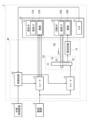
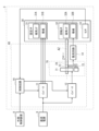
- FIG. 1 is a block diagram showing an example of the configuration of a motor device according to a first embodiment of the present invention.
- FIG. 2 is an explanatory diagram showing an example of the configuration of the stator and the rotor shown in FIG.
- FIG. 3 is an explanatory diagram showing one configuration example of the stator shown in FIG.
- FIG. 4 is an explanatory diagram showing one configuration example of the rotor shown in FIG.
- FIG. 5 is an explanatory diagram showing the relative positional relationship between the two magnetic cores and the shaft shown in FIG.
- FIG. 6 is an explanatory diagram illustrating an operation example of the power transmission device illustrated in FIG.
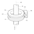
- FIG. 7 is an explanatory diagram showing the relative positional relationship between three magnetic cores and a shaft according to a modification of the first embodiment.
- FIG. 1 is a block diagram showing an example of the configuration of a motor device according to a first embodiment of the present invention.
- FIG. 2 is an explanatory diagram showing an example of the configuration of the stator and the
- FIG. 8A is an explanatory diagram illustrating a configuration example of a stator and a rotor according to a modified example of the first embodiment.
- FIG. 8B is an explanatory diagram illustrating a configuration example of a stator and a rotor according to another modified example of the first embodiment.
- FIG. 8C is an explanatory diagram illustrating a configuration example of a stator and a rotor according to another modified example of the first embodiment.
- FIG. 8D is an explanatory diagram illustrating a configuration example of a stator and a rotor according to another modified example of the first embodiment.
- FIG. 9A is an explanatory diagram illustrating a configuration example of a stator and a rotor according to another modified example of the first embodiment.
- FIG. 9B is an explanatory diagram illustrating an example of a configuration of a stator and a rotor according to another modified example of the first embodiment.
- FIG. 9C is an explanatory diagram illustrating an example of a configuration of a stator and a rotor according to another modified example of the first embodiment.
- FIG. 10 is a block diagram showing an example of the configuration of a motor device according to the second embodiment.
- FIG. 11 is an explanatory diagram showing an example of the configuration of the stator and rotor shown in FIG.
- FIG. 12 is an explanatory diagram showing the relative positional relationship between the two magnetic cores and the shaft shown in FIG. FIG.
- FIG. 13A is an explanatory diagram illustrating a configuration example of a stator and a rotor according to a modified example of the second embodiment.
- FIG. 13B is an explanatory diagram illustrating an example of a configuration of a stator and a rotor according to another modified example of the second embodiment.
- FIG. 13C is an explanatory diagram illustrating a configuration example of a stator and a rotor according to another modified example of the second embodiment.
- FIG. 13D is an explanatory diagram illustrating a configuration example of a stator and a rotor according to another modified example of the second embodiment.
- FIG. 14A is an explanatory diagram illustrating a configuration example of a stator and a rotor according to another modified example of the second embodiment.
- FIG. 14B is an explanatory diagram illustrating a configuration example of a stator and a rotor according to another modified example of the second embodiment.
- FIG. 15 is a block diagram showing an example of the configuration of a motor device according to the third embodiment.
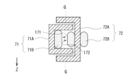
- FIG. 16 is an explanatory diagram illustrating an example of the configuration of the stator and rotor shown in FIG.
- FIG. 17 is an explanatory diagram showing the relative positional relationship between the two magnetic cores and the shaft shown in FIG.
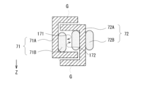
- FIG. 18A is an explanatory diagram illustrating a configuration example of a stator and a rotor according to a modified example of the third embodiment.
- FIG. 18B is an explanatory diagram illustrating a configuration example of a stator and a rotor according to another modified example of the third embodiment.
- FIG. 18C is an explanatory diagram illustrating a configuration example of a stator and a rotor according to another modified example of the third embodiment.
- FIG. 18D is an explanatory diagram illustrating a configuration example of a stator and a rotor according to another modified example of the third embodiment.
- FIG. 19A is an explanatory diagram illustrating a configuration example of a stator and a rotor according to another modified example of the third embodiment.
- FIG. 19B is an explanatory diagram illustrating a configuration example of a stator and a rotor according to another modified example of the third embodiment.
- First Embodiment [Configuration example] 1 shows an example of a configuration of a motor device 1 including a power transmission device according to a first embodiment of the present invention.
- the motor device 1 is connected to an external control device 8 and a DC power source 9.
- the external control device 8 is configured to instruct the motor device 1 on a rotation speed.
- the DC power source 9 is configured to supply DC power to the motor device 1.
- the motor device 1 is configured to generate a driving force, which is mechanical energy, based on an instruction from the external control device 8, using the DC power supplied from the DC power source 9.
- the motor device 1 includes a drive unit 10 and a motor 30.
- the drive unit 10 is configured to drive the motor 30.
- the drive unit 10 has inverters 11 and 12, a power transmission device 20, a rectifier circuit 14, and a control circuit 19.
- the inverter 11 is configured to convert the DC power supplied from the DC power source 9 into three-phase (U-phase, V-phase, W-phase) AC power based on instructions from the control circuit 19. The inverter 11 then supplies this three-phase AC power to the windings 31B (described below) of the stator 31 of the motor 30.
- the inverter 12 is configured to convert the DC power supplied from the DC power source 9 into single-phase AC power based on instructions from the control circuit 19. The inverter 12 then supplies this AC power to a winding 21B (described below) of a stator 21 of the power transmission device 20.
- the power transmission device 20 is configured to supply AC power to the rectifier circuit 14 by non-contact transmission.
- the power transmission device 20 has a stator 21, a rotor 22, a connecting member 23, and a shaft 24.
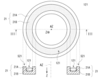
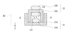
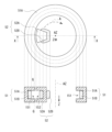
- FIG. 2 shows an example of the configuration of the stator 21 and the rotor 22.
- FIG. 2 also shows the cross-sectional structures of the stator 21 and the rotor 22 in a plane including the rotation axis AZ in the direction of the II-II arrows.
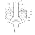
- FIG. 3 shows an example of the configuration of the stator 21.
- FIG. 3 also shows the cross-sectional structure of the stator 21 in a plane including the rotation axis AZ in the direction of the III-III arrows.
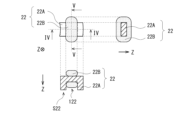
- FIG. 4 shows an example of the configuration of the rotor 22.
- FIG. 4 also shows the cross-sectional structure of the rotor 22 in a plane including the rotation axis AZ in the direction of the IV-IV arrows, and the cross-sectional structure of the rotor 22 in a plane including the rotation axis AZ in the direction of the V-V arrows.
- the stator 21 has a magnetic core 21A and a winding 21B.
- the rotor 22 has a magnetic core 22A and a winding 22B.
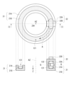
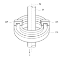
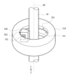
- Figure 5 shows the relative positions of the magnetic core 21A of the stator 21, the magnetic core 22A of the rotor 22, and the shaft 24 in the power transmission device 20.
- the stator 21 is a so-called stator, and is fixed to a housing (not shown) of the motor device 1.
- the magnetic core 21A of the stator 21 has a ring shape, for example as shown in Figs. 2, 3, and 5, and is provided in a plane intersecting with the rotation axis AZ, so as to surround the rotation axis AZ. That is, the magnetic core 21A has a shape that is continuous in the circumferential direction centered on the rotation axis AZ.
- the magnetic core 21A of the stator 21 has a groove-shaped recess 121 along the circumferential direction on the surface S21 (Figs. 3 and 5) in the direction opposite to the Z direction.
- the Z direction is the extension direction of the rotation axis AZ, and is the direction from the motor 30 toward the power transmission device 20.
- the winding 21B is wound around the magnetic core 21A along the recess 121.
- the winding 21B is connected to the inverter 12. As shown in Figs. 2 and 5, a part of the surface S21 of the stator 21 faces the rotor 22.
- the rotor 22 is a so-called rotor, and is configured to rotate around the rotation axis AZ. As shown in FIG. 1, the rotor 22 is connected to the shaft 24 via a connecting member 23.
- the magnetic core 22A of the rotor 22 is provided in a part of the circumferential direction centered on the rotation axis AZ, for example, as shown in FIG. 2.
- the rotor 22 rotates in the circumferential direction (for example, the circumferential direction A in FIG. 2) around the rotation axis AZ as the shaft 24 rotates around the rotation axis AZ.
- the magnetic core 22A of the rotor 22 is provided with a groove-shaped recess 122 extending in the circumferential direction on the Z-direction surface S22 (FIGS.
- the winding 22B is wound around the magnetic core 22A so as to pass through the recess 122, the surface of the magnetic core 22A opposite to the Z direction, and the two circumferential side surfaces of the magnetic core 22A.
- the winding 22B is connected to the rectifier circuit 14.
- Surface S22 of rotor 22 faces stator 21.
- the width of the rotor 22 in the radial direction (for example, the horizontal direction in FIG. 2) centered on the rotation axis AZ is the same as the width of the portion of the stator 21 corresponding to the rotor 22.
- the stator 21 and the rotor 22 are spaced apart by a gap G in the Z direction.
- a gap G is provided between the tips of the two convex portions on both sides of the recess 121 in the stator 21 and the tips of the two convex portions on both sides of the recess 122 in the rotor 22.
- the magnetic core 21A of the stator 21 and the magnetic core 22A of the rotor 22 are magnetically coupled via this gap G.
- the power transmission device 20 converts the AC power supplied from the inverter 12 at the ratio of the number of turns of the winding 21B and the number of turns of the winding 22B regardless of the position of the rotor 22, and supplies the converted AC power to the rectifier circuit 14.
- the power transmission device 20 is also called a rotary transformer.
- the connecting member 23 (FIG. 1) is configured to connect the rotor 22 to the shaft 24.
- the connecting member 23 is configured, for example, using a non-magnetic material.
- the shaft 24 is connected to the rotor 32 of the motor 30 and is configured to rotate around the rotation axis AZ in response to the driving force generated by the motor 30.
- the rectifier circuit 14 is configured to rectify the AC power supplied from the winding 22B of the rotor 22 and supply the rectified power to the winding 32B (described later) of the rotor 32 of the motor 30.
- the rectifier circuit 14 is connected to the shaft 24. That is, the winding 22B and the rotor 32 of the motor 30 are connected to the shaft 24, and therefore the rectifier circuit 14 is also connected to the shaft 24.
- the power rectified by the rectifier circuit 14 is directly supplied to the winding 32B, but this is not limited to this. Instead, for example, the power rectified by the rectifier circuit 14 may be supplied to the winding 32B via a stabilizing circuit including a capacitor.
- the control circuit 19 is configured to control the operation of the inverters 11, 12 based on instructions from the external control device 8 and a control signal indicating the rotation speed supplied from the motor 30. Specifically, the control circuit 19 controls the operation of the inverter 11 based on instructions from the external control device 8 and a control signal indicating the rotation speed of the motor 30, thereby controlling the rotation speed of the motor 30. The control circuit 19 also controls the strength of the magnetic field generated by the rotor 32 of the motor 30 by controlling the operation of the inverter 12 based on the control signal indicating the rotation speed supplied from the motor 30.
- control circuit 19 is configured to strengthen the magnetic field generated by the rotor 32 of the motor 30 when the rotation speed of the motor 30 is slow, and to weaken the magnetic field generated by the rotor 32 of the motor 30 when the rotation speed of the motor 30 is fast.
- the motor 30 is a wound field type synchronous motor.
- the motor 30 has a stator 31, a rotor 32, and a sensor 33.
- the stator 31 is a so-called stator, and is fixed to a housing (not shown) of the motor 30.
- the stator 31 has a magnetic core 31A and a winding 31B.
- the winding 31B is supplied with three-phase (U-phase, V-phase, W-phase) AC power generated by the inverter 11.
- the rotor 32 is a so-called rotor, and is configured to rotate the rotation axis AZ.
- the rotor 32 has a magnetic core 32A and a winding 32B. A signal rectified by the rectifier circuit 14 is supplied to the winding 32B.
- the sensor 33 is configured to detect the rotation speed of the rotor 32.
- the sensor 33 is configured to supply a control signal indicating the rotation speed of the rotor 32 to the control circuit 19.
- the motor device 1 controls the rotation speed of the motor 30 based on the three-phase (U-phase, V-phase, W-phase) AC power generated by the inverter 11, and controls the magnetic field generated by the rotor 32 of the motor 30 based on the single-phase AC power generated by the inverter 12. For example, when the rotation speed of the motor 30 is slow, the motor device 1 strengthens the magnetic field generated by the rotor 32 of the motor 30, and when the rotation speed of the motor 30 is fast, the magnetic field generated by the rotor 32 of the motor 30 is weakened. This makes it possible for the motor device 1 to increase the efficiency of the motor 30 over a wide range of rotation speeds.
- the rotation axis AZ corresponds to a specific example of a "rotation axis" in one embodiment of the present disclosure.
- the magnetic core 21A corresponds to a specific example of a "first magnetic core” in one embodiment of the present disclosure.
- the winding 21B corresponds to a specific example of a "first winding” in one embodiment of the present disclosure.
- the surface S21 corresponds to a specific example of a "first surface” in one embodiment of the present disclosure.
- the recess 121 corresponds to a specific example of a "first recess” in one embodiment of the present disclosure.
- the magnetic core 22A corresponds to a specific example of a "second magnetic core” in one embodiment of the present disclosure.
- the winding 22B corresponds to a specific example of a "second winding” in one embodiment of the present disclosure.
- the surface S22 corresponds to a specific example of a "second surface” in one embodiment of the present disclosure.
- the recess 122 corresponds to a specific example of a "second recess” in one embodiment of the present disclosure.
- the shaft 24 corresponds to a specific example of a "shaft” in one embodiment of the present disclosure.
- the connection member 23 corresponds to a specific example of a "connection member” in one embodiment of the present disclosure.
- the stator 31 corresponds to a specific example of a "motor stator” in an embodiment of the present disclosure.
- the magnetic core 31A corresponds to a specific example of a "first motor magnetic core” in an embodiment of the present disclosure.
- the winding 31B corresponds to a specific example of a "first motor winding” in an embodiment of the present disclosure.
- the rotor 32 corresponds to a specific example of a "motor rotor” in an embodiment of the present disclosure.
- the magnetic core 32A corresponds to a specific example of a "second motor magnetic core” in an embodiment of the present disclosure.
- the winding 32B corresponds to a specific example of a "second motor winding” in an embodiment of the present disclosure.
- the inverter 12 corresponds to a specific example of an "inverter” in an embodiment of the present disclosure.
- the rectifier circuit 14 corresponds to a specific example of a "rectifier circuit” in an embodiment of the present disclosure.
- the control circuit 19 controls the operation of the inverters 11 and 12 based on instructions from the external control device 8 and a control signal indicating the rotation speed supplied from the motor 30.
- the inverter 11 converts the DC power supplied from the DC power source 9 into three-phase (U-phase, V-phase, W-phase) AC power based on instructions from the control circuit 19, and supplies the three-phase AC power to the winding 31B of the stator 31 of the motor 30.
- the inverter 12 converts the DC power supplied from the DC power source 9 into single-phase AC power based on instructions from the control circuit 19, and supplies the AC power to the winding 21B of the stator 21 of the power transmission device 20.
- the power transmission device 20 supplies the AC power to the rectifier circuit 14 by non-contact transmission.
- the rectifier circuit 14 rectifies the AC power supplied from the winding 22B of the rotor 22, and supplies the rectified power to the winding 32B of the rotor 32 of the motor 30.
- the motor 30 generates a driving force, which is mechanical energy, based on the three-phase (U-phase, V-phase, W-phase) AC power supplied from the inverter 11. This causes the shaft 24 to rotate about the rotation axis AZ.
- the sensor 33 of the motor 30 supplies a control signal indicating the rotation speed of the motor 30 to the control circuit 19.
- AC power is supplied from the inverter 12 to the winding 21B of the stator 21 of the power transmission device 20.
- the magnetic core 21A of the stator 21 has a continuous shape in the circumferential direction of the rotation axis AZ, and the magnetic core 22A of the rotor 22 is provided in a portion of the circumferential direction of the rotation axis AZ.
- a portion of the surface S21 of the stator 21 opposite the Z direction faces the rotor 22 across a gap G.
- the rotor 22 rotates in the circumferential direction (for example, the circumferential direction A in FIG. 2) around the rotation axis AZ.
- FIG. 6 shows a cross-sectional view of the portion of the power transmission device 20 where the stator 21 and the rotor 22 face each other.
- the winding 21B of the stator 21 generates a magnetic field based on the AC power supplied from the inverter 12.
- a part of the surface S21 of the stator 21 faces the rotor 22 via a gap G. Therefore, in the power transmission device 20, as shown in FIG. 6, a magnetic path MP is generated that passes through the magnetic core 21A of the stator 21 and the magnetic core 22A of the rotor 22 so that the magnetic resistance is minimized.
- the winding 22B of the rotor 22 generates AC power based on the magnetic field in this magnetic path MP, and supplies the generated AC power to the rectifier circuit 14. In this way, the power transmission device 20 can supply AC power to the rectifier circuit 14 by non-contact transmission regardless of the position of the rotor 22.
- the power transmission device 20 transmits power non-contact, which can improve reliability compared to when power is transmitted by contact using, for example, slip rings and brushes.
- the rectifier circuit 14 rectifies the AC power supplied from the winding 22B of the rotor 22, and supplies the rectified power to the winding 32B of the rotor 32 of the motor 30. This generates a magnetic field in the rotor 32 of the motor 30. For example, when the rotation speed of the motor 30 is slow, the control circuit 19 strengthens the magnetic field generated by the rotor 32 of the motor 30, and when the rotation speed of the motor 30 is fast, the control circuit 19 weakens the magnetic field generated by the rotor 32 of the motor 30. This allows the motor device 1 to increase the efficiency of the motor 30 over a wide range of rotation speeds.
- the power transmission device 20 includes a first magnetic core (magnetic core 21A) having a continuous shape in the circumferential direction in a plane intersecting with the rotation axis AZ, a first winding (winding 21B) wound around the circumferential direction of the first magnetic core (magnetic core 21A), a second magnetic core (magnetic core 22A) that is rotatable around the rotation axis AZ and is provided in a portion of the circumferential direction in a plane intersecting with the rotation axis AZ and faces a portion of the first magnetic core (magnetic core 21A), and a second winding (winding 22B) wound around the second magnetic core (magnetic core 22A).
- the second magnetic core (magnetic core 22A) is provided in one direction with the rotation axis AZ as a reference in a plane intersecting with the rotation axis AZ.
- the magnetic core 22A is provided in a portion of the circumferential direction in a plane intersecting the rotation axis AZ, so that the inertial force when the rotor 22 rotates can be suppressed, thereby improving the efficiency of the motor 30.
- the magnetic core 22A is arranged in a portion of the circumferential direction in a plane intersecting the rotation axis AZ. This makes it possible to reduce the inertial force when the rotor 22 rotates, compared to a magnetic core having a ring shape. Therefore, in the power transmission device 20, the energy required when the motor 30 changes the rotation speed can be reduced, and the efficiency of the motor 30 can be improved.
- the power transmission device 20 is provided with a shaft 24 that can rotate around the rotation axis AZ, and a connection member 23 that connects the second magnetic core (magnetic core 22A) and the shaft 24.
- the connection member 23 is made of a non-magnetic material. This reduces the possibility that, for example, a magnetic field leaking from the gap G will reach the shaft 24. Therefore, for example, when the shaft 24 is made of a magnetic material, it reduces the possibility that a magnetic field will be transmitted to the rotor 32 of the motor 30 via the shaft 24. As a result, the motor device 1 can appropriately control the magnetic field generated by the rotor 32 of the motor 30 according to the rotation speed of the motor 30, thereby appropriately increasing the efficiency of the motor 30.
- the second magnetic core is provided in one direction based on the rotation axis in a plane intersecting with the rotation axis. This can increase the efficiency of the motor.
- a shaft that can rotate around a rotation axis and a connection member that connects the second magnetic core and the shaft are provided.
- This connection member is made of a non-magnetic material. This makes it possible, for example, to reduce the possibility that a magnetic field leaking from the gap will reach the shaft, thereby appropriately increasing the efficiency of the motor.
- the rotor 22 has the magnetic core 22A arranged in one direction with the rotation axis AZ as a reference in a plane intersecting with the rotation axis AZ, but this is not limited to this.
- the rotor 22 may have a plurality of magnetic cores 22A arranged in a plurality of directions with the rotation axis AZ as a reference in a plane intersecting with the rotation axis AZ.
- the rotor 22 has two magnetic cores 22A arranged in two directions with the rotation axis AZ as a reference.
- the two magnetic cores 22A are arranged in opposite directions with the rotation axis AZ in between.
- the winding 22B is wound around each of the two magnetic cores 22A in the same manner as in the above embodiment (FIG. 4).
- a gap G is provided between the tips of the two protruding portions on both sides of the recess 121 in the stator 21 and the tips of the two protruding portions on both sides of the recess 122 in the rotor 22, but this is not limited to this. Instead of this, for example, the gap G may be provided in a portion of the stator 21 and the rotor 22 other than the tips of the protruding portions. Below, this modified example will be described with several examples.
- FIG. 8A shows an example of the configuration of the stator 21 and rotor 22 according to this modified example.
- the width of the rotor 22 is wider than the width of the portion of the stator 21 that corresponds to the rotor 22.
- the tips of the two protrusions on both sides of the recess 121 in the stator 21 are contained in the recess 122 in the rotor 22. Therefore, in FIG. 8A, for example, a gap G is provided between the side of the left protrusion of the recess 121 in the stator 21 and the side of the left protrusion of the recess 122 in the rotor 22.
- a gap G is provided between the side of the right protrusion of the recess 121 in the stator 21 and the side of the right protrusion of the recess 122 in the rotor 22. This makes it possible to reduce leakage of the magnetic field from the magnetic cores 21A and 22A.
- FIG. 8B shows another example of the configuration of the stator 21 and rotor 22 according to this modified example.
- the width of the rotor 22 is narrower than the width of the portion of the stator 21 that corresponds to the rotor 22.
- the tips of the two protrusions on both sides of the recess 122 in the rotor 22 are contained in the recess 121 in the stator 21. Therefore, in FIG. 8B, for example, a gap G is provided between the side of the left protrusion of the recess 121 in the stator 21 and the side of the left protrusion of the recess 122 in the rotor 22.
- a gap G is provided between the side of the right protrusion of the recess 121 in the stator 21 and the side of the right protrusion of the recess 122 in the rotor 22. This can reduce leakage of the magnetic field from the magnetic cores 21A and 22A.
- Figures 8C and 8D show another example of the configuration of the stator 21 and rotor 22 according to this modified example.
- the width of the rotor 22 is approximately the same as the width of the portion of the stator 21 that corresponds to the rotor 22.
- the position of the rotor 22 and the position of the portion of the stator 21 that corresponds to the rotor 22 are shifted in the radial direction (horizontal direction in Figures 8C and 8D) centered on the rotation axis AZ.
- the tip of one of the two convex portions on both sides of the recess 121 in the stator 21 fits into the recess 122 in the rotor 22, and the tip of one of the two convex portions on both sides of the recess 122 in the rotor 22 fits into the recess 121 in the stator 21.
- a gap G is provided between the side of the left convex portion of the recess 121 in the stator 21 and the side of the left convex portion of the recess 122 in the rotor 22.
- a gap G is provided between the side of the right protrusion of the recess 121 in the stator 21 and the side of the right protrusion of the recess 122 in the rotor 22. This reduces leakage of the magnetic field from the magnetic cores 21A and 22A.
- FIG. 9A shows an example of the configuration of the stator 21 and rotor 22 according to this modified example.
- the rotor 22 has a flat plate shape, and unlike the above embodiment (FIG. 2, etc.), it does not have a recess and protrusions on either side of the recess.
- the width of the rotor 22 is approximately the same as the width of the portion of the stator 21 that corresponds to the rotor 22.
- a gap G is provided between the tips of the two protrusions on either side of the recess 121 in the stator 21 and the Z-direction surface S22 of the rotor 22. In this way, since the rotor 22 does not have protrusions, the rotor 22 can be made smaller. This makes it possible to suppress the inertial force when the rotor 22 rotates, thereby improving the efficiency of the motor 30.
- FIG. 9B shows another example of the configuration of the stator 21 and the rotor 22 according to this modified example.
- the rotor 22 has a flat plate shape, and unlike the above embodiment (FIG. 2, etc.), it does not have a recess and protrusions on both sides of the recess.
- the width of the rotor 22 is narrower than the width of the part of the stator 21 that corresponds to the rotor 22.
- the rotor 22 fits into the recess 121 in the stator 21.
- a gap G is provided between the side of the left protrusion of the recess 121 in the stator 21 and the side of the rotor 22.
- a gap G is provided between the side of the right protrusion of the recess 121 in the stator 21 and the side of the rotor 22.
- the rotor 22 since the rotor 22 does not have a protrusion, the rotor 22 can be made smaller. This makes it possible to suppress the inertial force when the rotor 22 rotates, thereby improving the efficiency of the motor 30.
- FIG. 9C shows another example of the configuration of the stator 21 and rotor 22 according to this modified example.
- the stator 21 has a flat plate shape and does not have a recess, unlike the above embodiment (FIG. 2, etc.).
- the width of the rotor 22 is approximately the same as the width of the portion of the stator 21 that corresponds to the rotor 22.
- a winding 21B is provided along the circumferential direction near the center in the radial direction of the magnetic core 21A of the stator 21.
- the winding 21B is fixed to the surface S21 of the magnetic core 21A in the direction opposite to the Z direction, for example, using an adhesive.
- a gap G is provided between the tips of the two protrusions on both sides of the recess 122 in the rotor 22 and the surface S21 of the stator 21.
- a motor device 2 according to a second embodiment will be described.
- the configuration of the power transmission device is different from that of the first embodiment.
- the same reference numerals are used to designate components that are substantially the same as those of the motor device 1 according to the first embodiment, and descriptions thereof will be omitted as appropriate.
- FIG. 10 shows an example of the configuration of a motor device 2 according to the second embodiment.
- the motor device 2 includes a drive unit 40.
- the drive unit 40 includes a power transmission device 50.
- the power transmission device 50 includes a stator 51, a rotor 52, a connecting member 53, and a shaft 24.
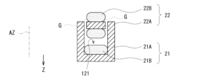
- FIG. 11 shows an example configuration of the stator 51 and rotor 52.
- FIG. 11 also shows the cross-sectional structure of the stator 51 and rotor 52 in a plane including the rotation axis AZ in the direction of the X-X arrows.
- the stator 51 has a magnetic core 51A and windings 51B.
- the rotor 52 has a magnetic core 52A and windings 52B.
- Figure 12 shows the relative positions of the magnetic core 51A of the stator 51, the magnetic core 52A of the rotor 52, and the shaft 24 in the power transmission device 50.
- the stator 51 is fixed to a housing (not shown) of the motor device 2.
- the magnetic core 51A of the stator 51 has a ring shape and is arranged in a plane intersecting with the rotation axis AZ, centered on the rotation axis AZ, so as to surround the rotation axis AZ.
- the magnetic core 51A has a shape that is continuous in the circumferential direction centered on the rotation axis AZ.
- the magnetic core 51A of the stator 51 has a groove-shaped recess 151 that runs along the circumferential direction on a surface S51 (FIG. 12) facing the rotation axis AZ.
- the winding 51B is wound around this recess 151 around the magnetic core 51A.
- the winding 51B is connected to the inverter 12. A part of the surface S51 of the stator 51 faces the rotor 52.
- the rotor 52 is configured to rotate around the rotation axis AZ. As shown in FIG. 10, the rotor 52 is connected to the shaft 24 via a connecting member 53.
- the magnetic core 52A of the rotor 52 is provided in a portion of the circumferential direction centered on the rotation axis AZ, for example, as shown in FIG. 11.
- the rotor 52 rotates in the circumferential direction (for example, the circumferential direction A in FIG. 11) around the rotation axis AZ as the shaft 24 rotates around the rotation axis AZ.
- the magnetic core 52A of the rotor 52 is provided with a groove-shaped recess 152 extending in the circumferential direction on the surface S52 (FIG. 12) facing away from the rotation axis AZ.
- the winding 52B is wound around the magnetic core 52A so as to pass through the recess 152, the surface of the magnetic core 52A facing the rotation axis AZ, and the two circumferential side surfaces of the magnetic core 52A.
- the winding 52B is connected to the rectifier circuit 14.
- Surface S52 of rotor 52 faces stator 51.
- the width of the rotor 52 in the Z direction is the same as the width of the stator 51 in the Z direction.
- the stator 51 and the rotor 52 are spaced apart by a gap G in the radial direction centered on the rotation axis AZ.
- a gap G is provided between the tips of the two convex portions on both sides of the recess 151 in the stator 51 and the tips of the two convex portions on both sides of the recess 152 in the rotor 52.
- the magnetic core 51A of the stator 51 and the magnetic core 52A of the rotor 52 are magnetically coupled via this gap G.
- the connecting member 53 ( Figure 10) is configured to connect the rotor 52 to the shaft 24.
- the winding 51B of the stator 51 of the power transmission device 50 is supplied with AC power from the inverter 12.
- the winding 51B of the stator 51 generates a magnetic field based on the AC power supplied from the inverter 12.
- a part of the surface S51 of the stator 51 faces the rotor 52 via a gap G. Therefore, in the power transmission device 50, as in the case of the first embodiment (FIG. 6), a magnetic path MP is generated that passes through the magnetic core 51A of the stator 51 and the magnetic core 52A of the rotor 52 so that the magnetic resistance is the lowest.
- the winding 52B of the rotor 52 generates AC power based on the magnetic field in this magnetic path MP, and supplies the generated AC power to the rectifier circuit 14.
- the power transmission device 50 can supply AC power to the rectifier circuit 14 by non-contact transmission regardless of the position of the rotor 52.
- the power transmission device 50 includes a first magnetic core (magnetic core 51A) having a continuous shape in the circumferential direction in a plane intersecting the rotation axis AZ, a first winding (winding 51B) wound around the first magnetic core (magnetic core 51A) in the circumferential direction, a second magnetic core (magnetic core 52A) that is rotatable around the rotation axis AZ and is provided in a portion of the circumferential direction in a plane intersecting the rotation axis AZ and faces a portion of the first magnetic core (magnetic core 51A), and a second winding (winding 52B) wound around the second magnetic core (magnetic core 52A).
- the magnetic core 52A is provided in a portion of the circumferential direction in a plane intersecting the rotation axis AZ, so that the inertial force when the rotor 52 rotates can be suppressed, and the efficiency of the motor 30 can be improved.
- the second magnetic core (magnetic core 52A) is arranged closer to the rotation axis AZ than the first magnetic core (magnetic core 51A). This allows the power transmission device 50 to reduce the moment of force when the rotor 52 rotates. In this way, in the power transmission device 50, the magnetic core 51A and the magnetic core 52A are opposed to each other, and the inertial force when the rotor 22 rotates can be suppressed, thereby increasing the efficiency of the motor 30.
- the first magnetic core (magnetic core 51A) has a first surface (surface S51) that can face the first magnetic core as the second magnetic core rotates
- the second magnetic core (magnetic core 52A) has a second surface (surface S52) that faces a part of the first surface (surface S51) of the first magnetic core (magnetic core 51A).
- the first surface (surface S51) and the second surface (surface S52) are parallel to the rotation axis AZ.
- the position of the gap G between the stator 51 and the rotor 52 is separated from the shaft 24 by more than the radial width of the rotor 52, so that, for example, in the case where a magnetic field leaks from the gap G, the possibility that the leaked magnetic field will reach the shaft 24 can be reduced. Therefore, for example, when the shaft 24 is made of a magnetic material, it is possible to reduce the possibility of a magnetic field being transmitted to the rotor 32 of the motor 30 via the shaft 24. As a result, the motor device 2 can appropriately control the magnetic field generated by the rotor 32 of the motor 30 according to the rotation speed of the motor 30, thereby appropriately increasing the efficiency of the motor 30.
- a first magnetic core having a continuous shape in the circumferential direction in a plane intersecting the rotation axis, a first winding wound around the first magnetic core, a second magnetic core that is rotatable around the rotation axis AZ and is provided in a portion of the circumferential direction in a plane intersecting the rotation axis AZ and faces a portion of the first magnetic core, and a second winding wound around the second magnetic core.
- the second magnetic core is located closer to the rotating shaft than the first magnetic core, which increases the efficiency of the motor.
- the first magnetic core has a first surface that can face the first magnetic core as the second magnetic core rotates
- the second magnetic core has a second surface that faces a part of the first surface of the first magnetic core.
- the first surface and the second surface are parallel to the axis of rotation.
- the rotor 52 has the magnetic core 52A provided in one direction with respect to the rotation axis AZ in a plane intersecting the rotation axis AZ, but this is not limited to this. Instead, for example, as in the case of the modified example 1-1 of the first embodiment (for example, FIG. 7), the rotor 52 may have a plurality of magnetic cores 52A provided in a plurality of directions with respect to the rotation axis AZ in a plane intersecting the rotation axis AZ.
- FIG. 13A shows an example of the configuration of the stator 51 and rotor 52 according to this modified example.
- the width of the rotor 52 in the Z direction is wider than the width of the stator 51 in the Z direction.
- the tips of the two protrusions on both sides of the recess 151 in the stator 51 are contained in the recess 152 in the rotor 52. Therefore, in FIG. 13A, for example, a gap G is provided between the side of the protrusion above the recess 151 in the stator 51 and the side of the protrusion above the recess 152 in the rotor 52.
- a gap G is provided between the side of the protrusion below the recess 151 in the stator 51 and the side of the protrusion below the recess 152 in the rotor 52. This can reduce leakage of the magnetic field from the magnetic cores 51A and 52A.
- FIG. 13B shows another example of the configuration of the stator 51 and rotor 52 according to this modified example.
- the width of the rotor 52 in the Z direction is narrower than the width of the stator 51 in the Z direction.
- the tips of the two protrusions on both sides of the recess 152 in the rotor 52 are contained in the recess 151 in the stator 51. Therefore, in FIG. 13B, for example, a gap G is provided between the side of the protrusion above the recess 151 in the stator 51 and the side of the protrusion above the recess 152 in the rotor 52.
- a gap G is provided between the side of the protrusion below the recess 151 in the stator 51 and the side of the protrusion below the recess 152 in the rotor 52. This can reduce leakage of the magnetic field from the magnetic cores 51A and 52A.
- FIG. 13C and 13D show another example of the configuration of the stator 51 and rotor 52 according to this modified example.
- the width of the rotor 52 in the Z direction is approximately the same as the width of the stator 51 in the Z direction.
- the position of the rotor 52 and the position of the stator 51 are shifted in the Z direction.
- the tip of one of the two convex portions on both sides of the concave portion 151 in the stator 51 fits into the concave portion 152 in the rotor 52
- the tip of one of the two convex portions on both sides of the concave portion 152 in the rotor 52 fits into the concave portion 151 in the stator 51.
- a gap G is provided between the side of the convex portion above the concave portion 151 in the stator 51 and the side of the convex portion above the concave portion 152 in the rotor 52.
- a gap G is provided between the side of the convex portion below the concave portion 151 in the stator 51 and the side of the convex portion below the concave portion 152 in the rotor 52. This reduces leakage of magnetic field from magnetic cores 51A and 52A.
- FIG. 14A shows an example of the configuration of the stator 51 and rotor 52 according to this modified example.
- the rotor 52 has a generally flat plate shape, and unlike the above embodiment (FIG. 11, etc.), it does not have a recess and protrusions on either side of the recess.
- the width of the rotor 52 in the Z direction is approximately the same as the width of the stator 51 in the Z direction.
- a gap G is provided between the tips of the two protrusions on either side of the recess 151 in the stator 51 and the surface S52 of the rotor 52 in the direction away from the rotation axis AZ. In this way, since the rotor 52 does not have a protrusion, the rotor 52 can be made smaller. This makes it possible to suppress the inertial force when the rotor 52 rotates, thereby improving the efficiency of the motor 30.
- the 14B shows another example of the configuration of the stator 51 and rotor 52 according to this modified example.
- the rotor 22 has a generally flat shape, and unlike the above embodiment (FIG. 11, etc.), it does not have a recess and protrusions on both sides of the recess.
- the width of the rotor 52 in the Z direction is narrower than the width of the stator 51 in the Z direction.
- the rotor 52 fits into the recess 151 in the stator 51.
- a gap G is provided between the side of the protrusion above the recess 151 in the stator 51 and the side of the rotor 52.
- a gap G is provided between the side of the protrusion below the recess 151 in the stator 51 and the side of the rotor 52.
- the rotor 52 since the rotor 52 does not have a protrusion, the rotor 52 can be made smaller. This makes it possible to suppress the inertial force when the rotor 52 rotates, thereby improving the efficiency of the motor 30.
- a motor device 3 according to a third embodiment will be described.
- the configuration of the power transmission device is different from that of the first and second embodiments.
- the same reference numerals are used to designate components that are substantially the same as those of the motor device 1 according to the first embodiment, and descriptions thereof will be omitted as appropriate.
- FIG. 15 shows an example of the configuration of a motor device 3 according to the third embodiment.
- the motor device 3 includes a drive unit 60.
- the drive unit 60 includes a power transmission device 70.
- the power transmission device 70 includes a stator 71, a rotor 72, a connecting member 73, and a shaft 24.
- FIG. 16 shows an example configuration of stator 71 and rotor 72.
- FIG. 16 also shows the cross-sectional structure of stator 71 and rotor 72 in a plane including rotation axis AZ in the direction of arrows XIV-XIV.
- Stator 71 has a magnetic core 71A and windings 71B.
- Rotor 72 has a magnetic core 72A and windings 72B.
- Figure 17 shows the relative positions of the magnetic core 71A of the stator 71, the magnetic core 72A of the rotor 72, and the shaft 24 in the power transmission device 70.
- the stator 71 is fixed to a housing (not shown) of the motor device 3.
- the magnetic core 71A of the stator 71 has a ring shape and is arranged in a plane intersecting with the rotation axis AZ, centered on the rotation axis AZ, so as to surround the rotation axis AZ.
- the magnetic core 71A has a shape that is continuous in the circumferential direction centered on the rotation axis AZ.
- the magnetic core 71A of the stator 71 has a groove-shaped recess 171 that runs along the circumferential direction on a surface S71 (FIG. 17) that faces away from the rotation axis AZ.
- the winding 71B is wound around the magnetic core 71A along the recess 171.
- the winding 71B is connected to the inverter 12. A part of the surface S71 of the stator 71 faces the rotor 72.
- the rotor 72 is configured to rotate around the rotation axis AZ. As shown in FIG. 15, the rotor 72 is connected to the shaft 24 via a connecting member 73.
- the magnetic core 72A of the rotor 72 is provided in a portion of the circumferential direction centered on the rotation axis AZ, for example, as shown in FIG. 16.
- the rotor 72 rotates in the circumferential direction (for example, the circumferential direction A in FIG. 16) around the rotation axis AZ as the shaft 24 rotates around the rotation axis AZ.
- the magnetic core 72A of the rotor 72 is provided with a groove-shaped recess 172 extending in the circumferential direction on the surface S72 (FIG. 17) facing the rotation axis AZ.
- the winding 72B is wound around the magnetic core 72A so as to pass through the recess 172, the surface of the magnetic core 72A facing away from the rotation axis AZ, and the two circumferential side surfaces of the magnetic core 72A.
- the winding 72B is connected to the rectifier circuit 14.
- Surface S72 of rotor 72 faces stator 71.
- the width of the rotor 72 in the Z direction is the same as the width of the stator 71 in the Z direction.
- the stator 71 and the rotor 72 are spaced apart by a gap G in the radial direction centered on the rotation axis AZ.
- a gap G is provided between the tips of the two convex portions on both sides of the recess 171 in the stator 71 and the tips of the two convex portions on both sides of the recess 172 in the rotor 72.
- the magnetic core 71A of the stator 71 and the magnetic core 72A of the rotor 72 are magnetically coupled via this gap G.
- the connecting member 73 ( Figure 15) is configured to connect the rotor 72 to the shaft 24.
- the winding 71B of the stator 71 of the power transmission device 70 is supplied with AC power from the inverter 12.
- the winding 71B of the stator 71 generates a magnetic field based on the AC power supplied from the inverter 12.
- a part of the surface S71 of the stator 71 faces the rotor 72 via a gap G. Therefore, in the power transmission device 70, as in the case of the first embodiment (FIG. 6), a magnetic path MP is generated that passes through the magnetic core 71A of the stator 71 and the magnetic core 72A of the rotor 72 so that the magnetic resistance is the lowest.
- the winding 72B of the rotor 72 generates AC power based on the magnetic field in this magnetic path MP, and supplies the generated AC power to the rectifier circuit 14.
- the power transmission device 70 can supply AC power to the rectifier circuit 14 by non-contact transmission regardless of the position of the rotor 72.
- the power transmission device 70 includes a first magnetic core (magnetic core 71A) having a continuous shape in the circumferential direction in a plane intersecting the rotation axis AZ, a first winding (winding 71B) wound around the circumferential direction of the first magnetic core (magnetic core 71A), a second magnetic core (magnetic core 72A) that is rotatable around the rotation axis AZ and is provided in a portion of the circumferential direction in a plane intersecting the rotation axis AZ and faces a portion of the first magnetic core (magnetic core 71A), and a second winding (winding 72B) wound around the second magnetic core (magnetic core 72A).
- the magnetic core 72A is provided in a portion of the circumferential direction in a plane intersecting the rotation axis AZ, so that the inertial force when the rotor 72 rotates can be suppressed, and the efficiency of the motor 30 can be improved.
- the first magnetic core (magnetic core 71A) has a first surface (surface S71) that can face the first magnetic core by rotating the second magnetic core
- the second magnetic core (magnetic core 72A) has a second surface (surface S72) that faces a part of the first surface (surface S71) of the first magnetic core (magnetic core 71A).
- the first surface (surface S71) and the second surface (surface S72) are parallel to the rotation axis AZ.
- the position of the gap G between the stator 71 and the rotor 72 is away from the shaft 24, so that, for example, in the case where a magnetic field leaks from the gap G, the possibility that the leaked magnetic field will reach the shaft 24 can be reduced. Therefore, for example, in the case where the shaft 24 is made of a magnetic material, the possibility that the magnetic field will be transmitted to the rotor 32 of the motor 30 via the shaft 24 can be reduced.
- the motor device 3 can appropriately control the magnetic field generated by the rotor 32 of the motor 30 according to the rotation speed of the motor 30, thereby appropriately increasing the efficiency of the motor 30.
- this embodiment has a first magnetic core that has a continuous shape in the circumferential direction in a plane that intersects with the rotation axis, a first winding wound around the circumferential direction of the first magnetic core, a second magnetic core that is rotatable around the rotation axis AZ and is provided in a portion of the circumferential direction in a plane that intersects with the rotation axis AZ and faces a portion of the first magnetic core, and a second winding wound around the second magnetic core.
- This can increase the efficiency of the motor.
- the first magnetic core has a first surface that can face the first magnetic core as the second magnetic core rotates
- the second magnetic core has a second surface that faces a part of the first surface of the first magnetic core.
- the first surface and the second surface are parallel to the axis of rotation.
- the rotor 72 has the magnetic core 72A provided in one direction with respect to the rotation axis AZ in a plane intersecting with the rotation axis AZ, but this is not limited to this. Instead, for example, as in the case of the modified example 1-1 of the first embodiment (for example, FIG. 7), the rotor 72 may have a plurality of magnetic cores 72A provided in a plurality of directions with respect to the rotation axis AZ in a plane intersecting with the rotation axis AZ.
- gaps G are provided between the tips of the two protruding portions on both sides of recess 171 in stator 71 and the tips of the two protruding portions on both sides of recess 172 in rotor 72, but this is not limited to the above. Instead, for example, gaps G may be provided in portions of stator 71 and rotor 72 other than the tips of the protruding portions, as in the case of modified example 1-2 of the first embodiment (Figs. 8A to 8D). Below, this modified example will be described with several examples.
- FIG. 18A shows an example of the configuration of the stator 71 and rotor 72 according to this modified example.
- the width of the rotor 72 in the Z direction is wider than the width of the stator 71 in the Z direction.
- the tips of the two protrusions on both sides of the recess 171 in the stator 71 are contained in the recess 172 in the rotor 72. Therefore, in FIG. 18A, for example, a gap G is provided between the side of the protrusion above the recess 151 in the stator 71 and the side of the protrusion above the recess 172 in the rotor 72.
- a gap G is provided between the side of the protrusion below the recess 171 in the stator 71 and the side of the protrusion below the recess 172 in the rotor 72. This can reduce leakage of the magnetic field from the magnetic cores 71A and 72A.
- FIG. 18B shows another example of the configuration of the stator 71 and rotor 72 according to this modified example.
- the width of the rotor 72 in the Z direction is narrower than the width of the stator 71 in the Z direction.
- the tips of the two protrusions on both sides of the recess 172 in the rotor 72 are contained in the recess 171 in the stator 71. Therefore, in FIG. 18B, for example, a gap G is provided between the side of the protrusion above the recess 171 in the stator 71 and the side of the protrusion above the recess 172 in the rotor 72.
- a gap G is provided between the side of the protrusion below the recess 171 in the stator 71 and the side of the protrusion below the recess 172 in the rotor 72. This can reduce leakage of the magnetic field from the magnetic cores 71A and 72A.
- 18C and 18D show another example of the configuration of the stator 71 and rotor 72 according to this modified example.
- the width of the rotor 72 in the Z direction is approximately the same as the width of the stator 71 in the Z direction.
- the position of the rotor 72 and the position of the stator 71 are shifted in the Z direction.
- the tip of one of the two convex portions on both sides of the concave portion 171 in the stator 71 fits into the concave portion 172 in the rotor 72
- the tip of one of the two convex portions on both sides of the concave portion 172 in the rotor 72 fits into the concave portion 171 in the stator 71.
- a gap G is provided between the side of the convex portion above the concave portion 171 in the stator 71 and the side of the convex portion above the concave portion 172 in the rotor 72.
- a gap G is provided between the side of the convex portion below the concave portion 171 in the stator 71 and the side of the convex portion below the concave portion 172 in the rotor 72. This reduces leakage of magnetic field from magnetic cores 71A and 72A.
- FIG. 19A shows an example of the configuration of the stator 71 and rotor 72 according to this modified example.
- the rotor 72 has a generally flat plate shape, and unlike the above embodiment (FIG. 16, etc.), it does not have a recess or protrusions on either side of the recess.
- the width of the rotor 72 in the Z direction is approximately the same as the width of the stator 71 in the Z direction.
- a gap G is provided between the tips of the two protrusions on either side of the recess 171 in the stator 71 and the surface S72 of the rotor 72 in the direction toward the rotation axis AZ. In this way, since the rotor 72 does not have a protrusion, the rotor 72 can be made smaller. This makes it possible to suppress the inertial force when the rotor 72 rotates, thereby improving the efficiency of the motor 30.
- FIG. 19B shows another example of the configuration of the stator 71 and rotor 72 according to this modified example.
- the rotor 72 has a generally flat shape, and unlike the above embodiment (FIG. 16, etc.), it does not have a recess and protrusions on both sides of the recess.
- the width of the rotor 72 in the Z direction is narrower than the width of the stator 71 in the Z direction.
- the rotor 72 fits into the recess 171 in the stator 71.
- a gap G is provided between the side of the protrusion above the recess 171 in the stator 71 and the side of the rotor 72.
- a gap G is provided between the side of the protrusion below the recess 171 in the stator 71 and the side of the rotor 72.
- the rotor 72 since the rotor 72 does not have a protrusion, the rotor 72 can be made smaller. This makes it possible to suppress the inertial force when the rotor 72 rotates, thereby improving the efficiency of the motor 30.
- the shapes of the stators 21, 51, 71 and the rotors 22, 52, 72 shown in the above embodiments are merely examples and are not limited to the shapes disclosed.
- a first magnetic core having a shape that is continuous in a circumferential direction in a plane that intersects with a rotation axis; a first winding wound around the first magnetic core in the circumferential direction; a second magnetic core that is rotatable about the rotation axis and is provided in a portion of the circumferential direction in a plane intersecting the rotation axis and facing a portion of the first magnetic core; a second winding wound around the second magnetic core.
- the first magnetic core has a first surface that can face the first magnetic core as the second magnetic core rotates;
- the power transfer device according to any one of (1) to (5), wherein the second magnetic core has a second surface that faces a portion of the first surface of the first magnetic core.
- the first magnetic core has a first recess provided in the first surface along the circumferential direction, the first winding is wound in the first recess along the circumferential direction, the second magnetic core has a second recess provided on the second surface so as to extend in the circumferential direction,
- the power transfer device according to (6), wherein the second winding is wound in the second recess.
- the power transfer device according to (6) or (7), wherein the first surface and the second surface are surfaces that intersect with the rotation axis.
- the power transfer device according to (6) or (7), wherein the first surface and the second surface are parallel to the rotation axis.
- the first magnetic core has, on the first surface, two first protrusions sandwiching the first recess
- the second magnetic core has, on the second surface, two second protrusions sandwiching the second recess
- the power transfer device according to (7), wherein the tips of the two first protrusions and the tips of the two second protrusions face each other.
- the first magnetic core has, on the first surface, two first protrusions sandwiching the first recess
- the second magnetic core has, on the second surface, two second protrusions sandwiching the second recess
- the power transfer device wherein tips of the two first protrusions of the first magnetic core fit into the second recesses of the second magnetic core.
- the first magnetic core has, on the first surface, two first protrusions sandwiching the first recess
- the second magnetic core has, on the second surface, two second protrusions sandwiching the second recess
- the first magnetic core has, on the first surface, two first protrusions sandwiching the first recess
- the second magnetic core has, on the second surface, two second protrusions sandwiching the second recess
- a tip end of one of the two first protrusions of the first magnetic core is fitted into the second recess of the second magnetic core
- the power transfer device according to (7), wherein a tip of one of the two second protrusions of the second magnetic core fits into the first recess of the first magnetic core.
- the first magnetic core has a first surface that can face the first magnetic core as the second magnetic core rotates, a first recess provided along the circumferential direction on the first surface, and two first protrusions that sandwich the first recess;
- the power transfer device according to claim 1 wherein tips of the two first protrusions and a part of the second magnetic core face each other.
- a motor having a motor stator including a first motor magnetic core and a first motor winding, and a motor rotor including a second motor magnetic core and a second motor winding; a shaft connected to the motor rotor; An inverter; a first magnetic core having a shape that is continuous in a circumferential direction in a plane that intersects with the shaft; a first winding connected to the inverter and wound around the first magnetic core in the circumferential direction; a second magnetic core that is rotatable about the shaft and is provided in a portion of the circumferential direction within a plane that intersects with the shaft and faces a portion of the first magnetic core; a second winding wound around the second magnetic core; and a rectifier circuit provided in a path connecting the second winding and the second motor winding.
Landscapes
- Engineering & Computer Science (AREA)
- Power Engineering (AREA)
- Iron Core Of Rotating Electric Machines (AREA)
Abstract
本発明の一実施の形態に係る電力伝送デバイスは、回転軸と交差する面内における周方向において連続な形状を有する第1の磁気コアと、第1の磁気コアの周方向に沿って巻かれた第1の巻線と、回転軸を中心として回動可能であり、回転軸と交差する面内における周方向の一部に設けられ、第1の磁気コアの一部と対向する第2の磁気コアと、第2の磁気コアに巻かれた第2の巻線とを備える。
Description
本発明は、非接触で電力を伝送する電力伝送デバイス、およびそのような電力伝送デバイスが設けられたモータ装置に関する。
例えば、モータには、巻線界磁式の同期モータ(EESM:Electrically Excited Synchronous Motor)がある。このモータは、巻線が巻き付けられた固定子と、巻線が巻き付けられた回転子とを有する。このモータでは、モータの回転速度に応じて、回転子に巻き付けられた巻線に流す電流を変化させることにより、モータの効率の向上を図ることができる。
ところで、固定子と回転子との間で電力を伝送可能なデバイスがある。例えば、特許文献1には、巻線が巻き付けられた固定子と、巻線が巻き付けられた回転子とを備え、固定子と回転子との間で電力を伝送可能な回転トランスが開示されている。
モータ装置では、モータの効率が高いことが望まれており、モータの効率のさらなる向上が期待されている。
モータの効率を高めることができる電力伝送デバイスおよびモータ装置を提供することが望ましい。
本発明の一実施の形態に係る電力伝送デバイスは、第1の磁気コアと、第1の巻線と、第2の磁気コアと、第2の巻線とを備えている。第1の磁気コアは、回転軸と交差する面内における周方向において連続な形状を有するものである。第1の巻線は、第1の磁気コアの周方向に沿って巻かれたものである。第2の磁気コアは、回転軸を中心として回動可能であり、回転軸と交差する面内における周方向の一部に設けられ、第1の磁気コアの一部と対向するものである。第2の巻線は、第2の磁気コアに巻かれたものである。
本発明の一実施の形態に係るモータ装置は、モータと、シャフトと、インバータと、第1の磁気コアと、第1の巻線と、第2の磁気コアと、第2の巻線と、整流回路とを備えている。モータは、第1のモータ磁気コアと第1のモータ巻線とを含むモータ固定子と、第2のモータ磁気コアと第2のモータ巻線とを含むモータ回転子とを有するものである。シャフトは、モータ回転子に接続されたものである。第1の磁気コアは、シャフトと交差する面内における周方向において連続な形状を有するものである。第1の巻線は、インバータに接続され、第1の磁気コアの周方向に沿って巻かれたものである。第2の磁気コアは、シャフトを中心として回動可能であり、シャフトと交差する面内における前記周方向の一部に設けられ、前記第1の磁気コアの一部と対向するものである。第2の巻線は、第2の磁気コアに巻かれたものである。整流回路は、第2の巻線および第2のモータ巻線を結ぶ経路に設けられたものである。
本発明の一実施の形態に係る電力伝送デバイスおよびモータ装置によれば、モータの効率を高めることができる。
以下、本発明の実施の形態について、図面を参照して詳細に説明する。なお、説明は以下の順序で行う。
1.第1の実施の形態
2.第2の実施の形態
3.第3の実施の形態
1.第1の実施の形態
2.第2の実施の形態
3.第3の実施の形態
<第1の実施の形態>
[構成例]
図1は、本発明の第1の実施の形態に係る電力伝送デバイスを備えたモータ装置1の一構成例を表すものである。モータ装置1は、外部制御装置8および直流電源9に接続される。外部制御装置8は、モータ装置1に対して、回転速度を指示するように構成される。直流電源9は、モータ装置1に対して直流電力を供給するように構成される。モータ装置1は、直流電源9から供給された直流電力を用いて、外部制御装置8からの指示に基づいて、機械的エネルギである駆動力を生成するように構成される。モータ装置1は、駆動部10と、モータ30とを備えている。
[構成例]
図1は、本発明の第1の実施の形態に係る電力伝送デバイスを備えたモータ装置1の一構成例を表すものである。モータ装置1は、外部制御装置8および直流電源9に接続される。外部制御装置8は、モータ装置1に対して、回転速度を指示するように構成される。直流電源9は、モータ装置1に対して直流電力を供給するように構成される。モータ装置1は、直流電源9から供給された直流電力を用いて、外部制御装置8からの指示に基づいて、機械的エネルギである駆動力を生成するように構成される。モータ装置1は、駆動部10と、モータ30とを備えている。
駆動部10は、モータ30を駆動するように構成される。駆動部10は、インバータ11,12と、電力伝送デバイス20と、整流回路14と、制御回路19とを有している。
インバータ11は、制御回路19からの指示に基づいて、直流電源9から供給された直流電力を3相(U相、V相、W相)の交流電力に変換するように構成される。そして、インバータ11は、この3相の交流電力を、モータ30の固定子31の巻線31B(後述)に供給するようになっている。
インバータ12は、制御回路19からの指示に基づいて、直流電源9から供給された直流電力を単相の交流電力に変換するように構成される。そして、インバータ12は、この交流電力を、電力伝送デバイス20の固定子21の巻線21B(後述)に供給するようになっている。
電力伝送デバイス20は、非接触伝送により、交流電力を整流回路14に供給するように構成される。電力伝送デバイス20は、固定子21と、回転子22と、接続部材23と、シャフト24とを有している。
図2は、固定子21および回転子22の一構成例を表すものである。図2には、II-II矢視方向の、回転軸AZを含む面内での固定子21および回転子22の断面構造をも描いている。図3は、固定子21の一構成例を表すものである。図3には、III-III矢視方向の、回転軸AZを含む面内での固定子21の断面構造をも描いている。図4は、回転子22の一構成例を表すものである。図4には、IV-IV矢視方向の、回転軸AZを含む面内での回転子22の断面構造、およびV-V矢視方向の、回転軸AZを含む面内での回転子22の断面構造をも描いている。固定子21は、磁気コア21Aと、巻線21Bとを有している。回転子22は、磁気コア22Aと、巻線22Bとを有している。
図5は、電力伝送デバイス20における、固定子21の磁気コア21A、回転子22の磁気コア22A、およびシャフト24の相対的な位置関係を表すものである。
固定子21は、いわゆるステータであり、モータ装置1の図示しない筐体に固定される。固定子21の磁気コア21Aは、例えば図2,3,5に示したように、リング形状を有し、回転軸AZと交差する面内において、回転軸AZを中心に、回転軸AZを取り囲むように設けられる。すなわち、磁気コア21Aは、回転軸AZを中心とした周方向に連続な形状を有する。固定子21の磁気コア21Aには、Z方向とは反対の方向の面S21(図3,5)において、周方向に沿って溝状の凹部121が設けられている。ここで、Z方向は、回転軸AZの延伸方向であり、モータ30から電力伝送デバイス20に向かう方向である。この磁気コア21Aには、この凹部121に沿って巻線21Bが巻かれている。巻線21Bは、インバータ12に接続される。図2,5に示したように、固定子21における面S21の一部は、回転子22と対向している。
回転子22は、いわゆるロータであり、回転軸AZを中心として回動するように構成される。回転子22は、図1に示したように、接続部材23を介してシャフト24に接続される。回転子22の磁気コア22Aは、例えば図2に示したように、回転軸AZを中心とした周方向のうちの一部に設けられる。回転子22は、シャフト24が回転軸AZを中心に回転することにより、回転軸AZを中心に、周方向(例えば、図2における周方向A)に回動するようになっている。回転子22の磁気コア22Aには、Z方向の面S22(図4,5)において、周方向に延伸する溝状の凹部122が設けられている。この磁気コア22Aには、この凹部122と、磁気コア22AにおけるZ方向とは反対側の面と、磁気コア22Aにおける周方向の2つの側面とを経由するように巻線22Bが巻かれている。巻線22Bは、整流回路14に接続される。回転子22における面S22は、固定子21と対向している。
この例では、例えば、図2に示したように、回転軸AZを中心とした径方向(例えば図2における横方向)における回転子22の幅は、固定子21のうちの回転子22に対応する部分の幅と同じである。固定子21および回転子22は、図2に示したように、Z方向において、ギャップGだけ離間して設けられる。言い換えれば、固定子21における凹部121の両側の2つの凸部の先端と、回転子22における凹部122の両側の2つの凸部の先端との間に、ギャップGがそれぞれ設けられている。固定子21の磁気コア21Aおよび回転子22の磁気コア22Aは、このギャップGを介して磁気的に結合される。この構成により、電力伝送デバイス20は、回転子22がどの位置にある場合でも、インバータ12から供給された交流電力を、巻線21Bの巻数および巻線22Bの巻数の比で変換し、変換された交流電力を整流回路14に供給するようになっている。電力伝送デバイス20は、ロータリトランスとも呼ばれる。
接続部材23(図1)は、回転子22をシャフト24に接続するように構成される。接続部材23は、例えば、非磁性材料を用いて構成される。
シャフト24は、モータ30の回転子32に接続され、モータ30が生成した駆動力に応じて、回転軸AZを中心に回転するように構成される。
整流回路14は、回転子22の巻線22Bから供給された交流電力を整流し、整流された電力をモータ30の回転子32の巻線32B(後述)に供給するように構成される。図示していないが、整流回路14は、シャフト24に接続される。すなわち、巻線22Bおよびモータ30の回転子32は、シャフト24に接続されるので、整流回路14もまた、シャフト24に接続される。なお、この例では、整流回路14により整流された電力を巻線32Bに直接供給したが、これに限定されるものではなく、これに代えて、例えば、整流回路14により整流された電力を、キャパシタを含む安定化回路を介して、巻線32Bに供給してもよい。
制御回路19は、外部制御装置8からの指示、およびモータ30から供給された回転速度を示す制御信号に基づいて、インバータ11,12の動作を制御するように構成される。具体的には、制御回路19は、外部制御装置8からの指示、およびモータ30における回転速度を示す制御信号に基づいて、インバータ11の動作を制御することにより、モータ30の回転速度を制御する。また、制御回路19は、モータ30から供給された回転速度を示す制御信号に基づいて、インバータ12の動作を制御することにより、モータ30の回転子32が生成する磁界の強さを制御する。具体的には、制御回路19は、例えば、モータ30の回転速度が遅い場合には、モータ30の回転子32が生成する磁界を強くし、モータ30の回転速度が速い場合には、モータ30の回転子32が生成する磁界を弱くするようになっている。
モータ30は、巻線界磁式の同期モータである。モータ30は、固定子31と、回転子32と、センサ33とを有している。
固定子31は、いわゆるステータであり、モータ30の図示しない筐体に固定される。固定子31は、磁気コア31Aと、巻線31Bとを有している。巻線31Bには、インバータ11により生成された3相(U相、V相、W相)の交流電力が供給されるようになっている。
回転子32は、いわゆるロータであり、回転軸AZを回転するように構成される。回転子32は、磁気コア32Aと、巻線32Bとを有している。巻線32Bには、整流回路14により整流された信号が供給されるようになっている。
センサ33は、回転子32の回転速度を検出するように構成される。そして、センサ33は、回転子32の回転速度を示す制御信号を制御回路19に供給するようになっている。
この構成により、モータ装置1では、インバータ11が生成した3相(U相、V相、W相)の交流電力に基づいて、モータ30の回転速度を制御し、インバータ12が生成した単相の交流電力に基づいて、モータ30の回転子32が生成する磁界を制御する。モータ装置1では、例えば、モータ30の回転速度が遅い場合には、モータ30の回転子32が生成する磁界を強くし、モータ30の回転速度が速い場合には、モータ30の回転子32が生成する磁界を弱くする。これにより、モータ装置1では、幅広い回転速度において、モータ30の効率を高めることが出来るようになっている。
ここで、回転軸AZは、本開示の一実施の形態における「回転軸」の一具体例に対応する。磁気コア21Aは、本開示の一実施の形態における「第1の磁気コア」の一具体例に対応する。巻線21Bは、本開示の一実施の形態における「第1の巻線」の一具体例に対応する。面S21は、本開示の一実施の形態における「第1の面」の一具体例に対応する。凹部121は、本開示の一実施の形態における「第1の凹部」の一具体例に対応する。磁気コア22Aは、本開示の一実施の形態における「第2の磁気コア」の一具体例に対応する。巻線22Bは、本開示の一実施の形態における「第2の巻線」の一具体例に対応する。面S22は、本開示の一実施の形態における「第2の面」の一具体例に対応する。凹部122は、本開示の一実施の形態における「第2の凹部」の一具体例に対応する。シャフト24は、本開示の一実施の形態における「シャフト」の一具体例に対応する。接続部材23は、本開示の一実施の形態における「接続部材」の一具体例に対応する。
固定子31は、本開示の一実施の形態における「モータ固定子」の一具体例に対応する。磁気コア31Aは、本開示の一実施の形態における「第1のモータ磁気コア」の一具体例に対応する。巻線31Bは、本開示の一実施の形態における「第1のモータ巻線」の一具体例に対応する。回転子32は、本開示の一実施の形態における「モータ回転子」の一具体例に対応する。磁気コア32Aは、本開示の一実施の形態における「第2のモータ磁気コア」の一具体例に対応する。巻線32Bは、本開示の一実施の形態における「第2のモータ巻線」の一具体例に対応する。インバータ12は、本開示の一実施の形態における「インバータ」の一具体例に対応する。整流回路14は、本開示の一実施の形態における「整流回路」の一具体例に対応する。
[動作および作用]
続いて、本実施の形態のモータ装置1の動作および作用について説明する。
続いて、本実施の形態のモータ装置1の動作および作用について説明する。
(全体動作概要)
制御回路19は、外部制御装置8からの指示、およびモータ30から供給された回転速度を示す制御信号に基づいて、インバータ11,12の動作を制御する。インバータ11は、制御回路19からの指示に基づいて、直流電源9から供給された直流電力を3相(U相、V相、W相)の交流電力に変換し、この3相の交流電力を、モータ30の固定子31の巻線31Bに供給する。インバータ12は、制御回路19からの指示に基づいて、直流電源9から供給された直流電力を単相の交流電力に変換し、この交流電力を、電力伝送デバイス20の固定子21の巻線21Bに供給する。電力伝送デバイス20は、非接触伝送により、交流電力を整流回路14に供給する。整流回路14は、回転子22の巻線22Bから供給された交流電力を整流し、整流された電力をモータ30の回転子32の巻線32Bに供給する。モータ30は、インバータ11から供給された3相(U相、V相、W相)の交流電力に基づいて、機械的エネルギである駆動力を生成する。これにより、シャフト24が回転軸AZを中心に回転する。モータ30のセンサ33は、モータ30の回転速度を示す制御信号を制御回路19に供給する。
制御回路19は、外部制御装置8からの指示、およびモータ30から供給された回転速度を示す制御信号に基づいて、インバータ11,12の動作を制御する。インバータ11は、制御回路19からの指示に基づいて、直流電源9から供給された直流電力を3相(U相、V相、W相)の交流電力に変換し、この3相の交流電力を、モータ30の固定子31の巻線31Bに供給する。インバータ12は、制御回路19からの指示に基づいて、直流電源9から供給された直流電力を単相の交流電力に変換し、この交流電力を、電力伝送デバイス20の固定子21の巻線21Bに供給する。電力伝送デバイス20は、非接触伝送により、交流電力を整流回路14に供給する。整流回路14は、回転子22の巻線22Bから供給された交流電力を整流し、整流された電力をモータ30の回転子32の巻線32Bに供給する。モータ30は、インバータ11から供給された3相(U相、V相、W相)の交流電力に基づいて、機械的エネルギである駆動力を生成する。これにより、シャフト24が回転軸AZを中心に回転する。モータ30のセンサ33は、モータ30の回転速度を示す制御信号を制御回路19に供給する。
[動作および作用]
続いて、本実施の形態の電力伝送デバイス20の動作および作用について説明する。
続いて、本実施の形態の電力伝送デバイス20の動作および作用について説明する。
電力伝送デバイス20の固定子21の巻線21Bには、インバータ12から交流電力が供給される。
例えば図2に示したように、固定子21の磁気コア21Aは、回転軸AZの周方向に連続な形状を有し、回転子22の磁気コア22Aは、回転軸AZの周方向のうちの一部に設けられる。すなわち、固定子21における、Z方向とは反対の面S21の一部は、ギャップGを介して、回転子22と対向している。そして、回転子22は、回転軸AZを中心に、周方向(例えば、図2における周方向A)に回動する。
図6は、電力伝送デバイス20における、固定子21と回転子22とが対向している部分の断面図を表すものである。固定子21の巻線21Bは、インバータ12から供給された交流電力に基づいて磁界を発生させる。電力伝送デバイス20では、固定子21における面S21の一部が、ギャップGを介して回転子22と対向している。よって、電力伝送デバイス20では、図6に示したように、磁気抵抗が最も低くなるように、固定子21の磁気コア21Aおよび回転子22の磁気コア22Aを経由する磁路MPが生成される。そして、回転子22の巻線22Bは、この磁路MPにおける磁界に基づいて交流電力を生成し、生成した交流電力を整流回路14に供給する。このようにして、電力伝送デバイス20は、回転子22がどの位置にある場合でも、非接触伝送により、交流電力を整流回路14に供給することができる。
このように、電力伝送デバイス20では、非接触伝送により電力が伝送されるので、例えばスリップリングおよびブラシを用いて接触伝送により電力を伝送する場合に比べて、信頼性を高めることができる。
整流回路14は、回転子22の巻線22Bから供給された交流電力を整流し、整流された電力をモータ30の回転子32の巻線32Bに供給する。これにより、モータ30の回転子32では、磁界が生成される。制御回路19は、例えば、モータ30の回転速度が遅い場合には、モータ30の回転子32が生成する磁界を強くし、モータ30の回転速度が速い場合には、モータ30の回転子32が生成する磁界を弱くする。これにより、モータ装置1では、幅広い回転速度において、モータ30の効率を高めることが出来る。
このように、電力伝送デバイス20では、回転軸AZと交差する面内における周方向において連続な形状を有する第1の磁気コア(磁気コア21A)と、第1の磁気コア(磁気コア21A)の周方向に沿って巻かれた第1の巻線(巻線21B)と、回転軸AZを中心として回動可能であり、回転軸AZと交差する面内における周方向の一部に設けられ、第1の磁気コア(磁気コア21A)の一部と対向する第2の磁気コア(磁気コア22A)と、第2の磁気コア(磁気コア22A)に巻かれた第2の巻線(巻線22B)とを設けるようにした。具体的には、この例では、第2の磁気コア(磁気コア22A)は、回転軸AZと交差する面内において、回転軸AZを基準として1つの方向に設けられるようにした。このように、電力伝送デバイス20では、磁気コア22Aは、回転軸AZと交差する面内における周方向の一部に設けられているので、回転子22が回動する際の慣性力を抑えることができるため、モータ30の効率を高めることができる。
すなわち、仮に、回転子22を、固定子21と同様に、リング形状を有する磁気コアを用いて構成した場合には、回転子22が回動する際の慣性力が大きくなってしまう。この場合には、例えば、モータ30が回転速度を変化させる場合に、大きなエネルギが必要になってしまい、モータ30の効率が低下してしまう。
一方、本実施の形態に係る電力伝送デバイス20では、磁気コア22Aは、回転軸AZと交差する面内における周方向の一部に設けられるようにした。これにより、リング形状を有する磁気コアに比べて、回転子22が回動する際の慣性力を抑えることができる。よって、電力伝送デバイス20では、モータ30が回転速度を変化させる場合に必要なエネルギを抑えることができるので、モータ30の効率を高めることができる。
また、電力伝送デバイス20では、回転軸AZを中心に回転可能なシャフト24と、第2の磁気コア(磁気コア22A)とシャフト24とを接続する接続部材23とを設けるようにした。この接続部材23は、非磁性材料を用いて構成されるようにした。これにより、例えば、ギャップGから磁界が漏れる場合において、この漏れた磁界がシャフト24にまでおよぶ可能性を低減することができる。よって、例えば、シャフト24が磁性部材を用いて構成された場合において、このシャフト24を介してモータ30の回転子32に磁界が伝わる可能性を低減することができる。これにより、モータ装置1では、モータ30の回転速度に応じて、適切に、モータ30の回転子32が生成する磁界を制御することができるので、モータ30の効率を適切に高めることが出来る。
[効果]
以上のように本実施の形態では、回転軸と交差する面内における周方向において連続な形状を有する第1の磁気コアと、第1の磁気コアの周方向に沿って巻かれた第1の巻線と、回転軸AZを中心として回動可能であり、回転軸AZと交差する面内における周方向の一部に設けられ、第1の磁気コアの一部と対向する第2の磁気コアと、第2の磁気コアに巻かれた第2の巻線とを設けるようにした。具体的には、この例では、第2の磁気コアは、回転軸と交差する面内において、回転軸を基準として1つの方向に設けられるようにした。これにより、モータの効率を高めることができる。
以上のように本実施の形態では、回転軸と交差する面内における周方向において連続な形状を有する第1の磁気コアと、第1の磁気コアの周方向に沿って巻かれた第1の巻線と、回転軸AZを中心として回動可能であり、回転軸AZと交差する面内における周方向の一部に設けられ、第1の磁気コアの一部と対向する第2の磁気コアと、第2の磁気コアに巻かれた第2の巻線とを設けるようにした。具体的には、この例では、第2の磁気コアは、回転軸と交差する面内において、回転軸を基準として1つの方向に設けられるようにした。これにより、モータの効率を高めることができる。
本実施の形態では、回転軸を中心に回転可能なシャフトと、第2の磁気コアとシャフトとを接続する接続部材とを設けるようにした。この接続部材は、非磁性材料を用いて構成されるようにした。これにより、例えば、ギャップから磁界が漏れる場合において、この漏れた磁界がシャフトにまでおよぶ可能性を低減することができるので、モータの効率を適切に高めることが出来る。
[変形例1-1]
上記実施の形態では、回転子22は、回転軸AZと交差する面内において、回転軸AZを基準として1つの方向に設けられた磁気コア22Aを有するようにしたが、これに限定されるものではない。これに代えて、例えば、図7に示すように、回転子22は、回転軸AZと交差する面内において、回転軸AZを基準として複数の方向に設けられた複数の磁気コア22Aを有するようにしてもよい。この例では、回転子22は、回転軸AZを基準として2つの方向に設けられた2つの磁気コア22Aを有している。2つの磁気コア22Aは、回転軸AZを挟んで互いに反対の方向に設けられる。図示していないが、2つの磁気コア22Aのそれぞれには、上記実施の形態の場合(図4)と同様に、巻線22Bが巻かれる。
上記実施の形態では、回転子22は、回転軸AZと交差する面内において、回転軸AZを基準として1つの方向に設けられた磁気コア22Aを有するようにしたが、これに限定されるものではない。これに代えて、例えば、図7に示すように、回転子22は、回転軸AZと交差する面内において、回転軸AZを基準として複数の方向に設けられた複数の磁気コア22Aを有するようにしてもよい。この例では、回転子22は、回転軸AZを基準として2つの方向に設けられた2つの磁気コア22Aを有している。2つの磁気コア22Aは、回転軸AZを挟んで互いに反対の方向に設けられる。図示していないが、2つの磁気コア22Aのそれぞれには、上記実施の形態の場合(図4)と同様に、巻線22Bが巻かれる。
[変形例1-2]
上記実施の形態では、例えば図2に示したように、固定子21における凹部121の両側の2つの凸部の先端と、回転子22における凹部122の両側の2つの凸部の先端との間にギャップGを設けたが、これに限定されるものではない。これに代えて、例えば、固定子21および回転子22における、凸部の先端以外の部分にギャップGを設けてもよい。以下に、本変形例について、いくつか例を挙げて説明する。
上記実施の形態では、例えば図2に示したように、固定子21における凹部121の両側の2つの凸部の先端と、回転子22における凹部122の両側の2つの凸部の先端との間にギャップGを設けたが、これに限定されるものではない。これに代えて、例えば、固定子21および回転子22における、凸部の先端以外の部分にギャップGを設けてもよい。以下に、本変形例について、いくつか例を挙げて説明する。
図8Aは、本変形例に係る固定子21および回転子22の一構成例を表すものである。この例では、回転子22の幅は、固定子21のうちの回転子22に対応する部分の幅よりも広い。この例では、固定子21における凹部121の両側の2つの凸部の先端は、回転子22における凹部122に収まっている。よって、図8Aにおいて、例えば、固定子21における凹部121の左の凸部の側面と、回転子22における凹部122の左の凸部の側面との間に、ギャップGが設けられる。同様に、例えば、固定子21における凹部121の右の凸部の側面と、回転子22における凹部122の右の凸部の側面との間に、ギャップGが設けられる。これにより、磁気コア21A,22Aからの磁界の漏れを少なくすることができる。
図8Bは、本変形例に係る他の固定子21および回転子22の一構成例を表すものである。この例では、回転子22の幅は、固定子21のうちの回転子22に対応する部分の幅よりも狭い。この例では、回転子22における凹部122の両側の2つの凸部の先端は、固定子21における凹部121に収まっている。よって、図8Bにおいて、例えば、固定子21における凹部121の左の凸部の側面と、回転子22における凹部122の左の凸部の側面との間に、ギャップGが設けられる。同様に、例えば、固定子21における凹部121の右の凸部の側面と、回転子22における凹部122の右の凸部の側面との間に、ギャップGが設けられる。これにより、磁気コア21A,22Aからの磁界の漏れを少なくすることができる。
図8C,8Dは、本変形例に係る他の固定子21および回転子22の一構成例を表すものである。この例では、回転子22の幅は、固定子21のうちの回転子22に対応する部分の幅とほぼ同じである。この例では、回転軸AZを中心とした径方向(図8C,8Dにおける横方向)において、回転子22の位置と、固定子21のうちの回転子22に対応する部分の位置とをずらしている。よって、固定子21における凹部121の両側の2つの凸部のうちの1つの先端は、回転子22における凹部122に収まり、回転子22における凹部122の両側の2つの凸部のうちの1つの先端は、固定子21における凹部121に収まる。よって、例えば、固定子21における凹部121の左の凸部の側面と、回転子22における凹部122の左の凸部の側面との間に、ギャップGが設けられる。同様に、例えば、固定子21における凹部121の右の凸部の側面と、回転子22における凹部122の右の凸部の側面との間に、ギャップGが設けられる。これにより、磁気コア21A,22Aからの磁界の漏れを少なくすることができる。
[変形例1-3]
上記実施の形態では、例えば図2に示したように、固定子21が凹部121を有するとともに、回転子22が凹部122を有するようにしたが、これに限定されるものではない。以下に、本変形例について、いくつか例を挙げて説明する。
上記実施の形態では、例えば図2に示したように、固定子21が凹部121を有するとともに、回転子22が凹部122を有するようにしたが、これに限定されるものではない。以下に、本変形例について、いくつか例を挙げて説明する。
図9Aは、本変形例に係る固定子21および回転子22の一構成例を表すものである。この例では、回転子22は、平板形状を有し、上記実施の形態の場合(図2等)とは異なり、凹部および凹部の両側の凸部を有していない。この例では、回転子22の幅は、固定子21のうちの回転子22に対応する部分の幅とほぼ同じである。この例では、固定子21における凹部121の両側の2つの凸部の先端と、回転子22のZ方向の面S22との間に、ギャップGが設けられる。このように、回転子22は、凸部を有していないので、回転子22を小型化することができる。これにより、回転子22が回動する際の慣性力を抑えることができるため、モータ30の効率を高めることができる。
図9Bは、本変形例に係る他の固定子21および回転子22の一構成例を表すものである。回転子22は、平板形状を有し、上記実施の形態の場合(図2等)とは異なり、凹部および凹部の両側の凸部を有していない。この例では、回転子22の幅は、固定子21のうちの回転子22に対応する部分の幅より狭い。この例では、回転子22は、固定子21における凹部121に収まっている。この例では、固定子21における凹部121の左の凸部の側面と、回転子22の側面との間に、ギャップGが設けられる。同様に、例えば、固定子21における凹部121の右の凸部の側面と、回転子22の側面との間に、ギャップGが設けられる。このように、回転子22は、凸部を有していないので、回転子22を小型化することができる。これにより、回転子22が回動する際の慣性力を抑えることができるため、モータ30の効率を高めることができる。
図9Cは、本変形例に係る他の固定子21および回転子22の一構成例を表すものである。この例では、固定子21は、平板形状を有し、上記実施の形態の場合(図2等)とは異なり、凹部を有していない。この例では、回転子22の幅は、固定子21のうちの回転子22に対応する部分の幅とほぼ同じである。固定子21の磁気コア21Aにおける、径方向の中央付近には、周方向に沿って巻線21Bが設けられる。この例では、巻線21Bは、磁気コア21AにおけるZ方向とは反対の方向の面S21に、例えば接着剤などを用いて固定される。この例では、回転子22における凹部122の両側の2つの凸部の先端と、固定子21の面S21との間に、ギャップGが設けられる。
[その他の変形例]
また、これらの変形例のうちの2以上を組み合わせてもよい。
また、これらの変形例のうちの2以上を組み合わせてもよい。
<2.第2の実施の形態>
次に、第2の実施の形態に係るモータ装置2について説明する。本実施の形態は、電力伝送デバイスの構成が、上記第1の実施の形態と異なるものである。なお、上記第1の実施の形態に係るモータ装置1と実質的に同一の構成部分には同一の符号を付し、適宜説明を省略する。
次に、第2の実施の形態に係るモータ装置2について説明する。本実施の形態は、電力伝送デバイスの構成が、上記第1の実施の形態と異なるものである。なお、上記第1の実施の形態に係るモータ装置1と実質的に同一の構成部分には同一の符号を付し、適宜説明を省略する。
図10は、第2の実施の形態に係るモータ装置2の一構成例を表すものである。モータ装置2は、駆動部40を備えている。駆動部40は、電力伝送デバイス50を有している。電力伝送デバイス50は、固定子51と、回転子52と、接続部材53と、シャフト24とを有している。
図11は、固定子51および回転子52の一構成例を表すものである。図11には、X-X矢視方向の、回転軸AZを含む面内での固定子51および回転子52の断面構造をも描いている。固定子51は、磁気コア51Aと、巻線51Bとを有している。回転子52は、磁気コア52Aと、巻線52Bとを有している。
図12は、電力伝送デバイス50における、固定子51の磁気コア51A、回転子52の磁気コア52A、およびシャフト24の相対的な位置関係を表すものである。
固定子51は、モータ装置2の図示しない筐体に固定される。固定子51の磁気コア51Aは、リング形状を有し、回転軸AZと交差する面内において、回転軸AZを中心に、回転軸AZを取り囲むように設けられる。すなわち、磁気コア51Aは、回転軸AZを中心とした周方向に連続な形状を有する。固定子51の磁気コア51Aには、回転軸AZに向かう方向の面S51(図12)において、周方向に沿って溝状の凹部151が設けられている。この磁気コア51Aには、この凹部151に沿って巻線51Bが巻かれている。巻線51Bは、インバータ12に接続される。固定子51における面S51の一部は、回転子52と対向している。
回転子52は、回転軸AZを中心として回動するように構成される。回転子52は、図10に示したように、接続部材53を介してシャフト24に接続される。回転子52の磁気コア52Aは、例えば図11に示したように、回転軸AZを中心とした周方向のうちの一部に設けられる。回転子52は、シャフト24が回転軸AZを中心に回転することにより、回転軸AZを中心に、周方向(例えば、図11における周方向A)に回動するようになっている。回転子52の磁気コア52Aには、回転軸AZから遠ざかる方向の面S52(図12)において、周方向に延伸する溝状の凹部152が設けられている。この磁気コア52Aには、この凹部152と、磁気コア52Aにおける回転軸AZに向かう方向の面と、磁気コア52Aにおける周方向の2つの側面とを経由するように巻線52Bが巻かれている。巻線52Bは、整流回路14に接続される。回転子52における面S52は、固定子51と対向している。
この例では、例えば、図11に示したように、Z方向における回転子52の幅は、Z方向における固定子51の幅と同じである。固定子51および回転子52は、図11に示したように、回転軸AZを中心とした径方向において、ギャップGだけ離間して設けられる。言い換えれば、固定子51における凹部151の両側の2つの凸部の先端と、回転子52における凹部152の両側の2つの凸部の先端との間に、ギャップGがそれぞれ設けられている。固定子51の磁気コア51Aおよび回転子52の磁気コア52Aは、このギャップGを介して磁気的に結合される。
接続部材53(図10)は、回転子52をシャフト24に接続するように構成される。
電力伝送デバイス50の固定子51の巻線51Bには、インバータ12から交流電力が供給される。固定子51の巻線51Bは、インバータ12から供給された交流電力に基づいて磁界を発生させる。電力伝送デバイス50では、固定子51における面S51の一部が、ギャップGを介して回転子52と対向している。よって、電力伝送デバイス50では、上記第1の実施の形態の場合(図6)と同様に、磁気抵抗が最も低くなるように、固定子51の磁気コア51Aおよび回転子52の磁気コア52Aを経由する磁路MPが生成される。そして、回転子52の巻線52Bは、この磁路MPにおける磁界に基づいて交流電力を生成し、生成した交流電力を整流回路14に供給する。このようにして、電力伝送デバイス50は、回転子52がどの位置にある場合でも、非接触伝送により、交流電力を整流回路14に供給することができる。
このように、電力伝送デバイス50では、回転軸AZと交差する面内における周方向において連続な形状を有する第1の磁気コア(磁気コア51A)と、第1の磁気コア(磁気コア51A)に周方向に沿って巻かれた第1の巻線(巻線51B)と、回転軸AZを中心として回動可能であり、回転軸AZと交差する面内における周方向の一部に設けられ、第1の磁気コア(磁気コア51A)の一部と対向する第2の磁気コア(磁気コア52A)と、第2の磁気コア(磁気コア52A)に巻かれた第2の巻線(巻線52B)とを設けるようにした。このように、電力伝送デバイス50では、磁気コア52Aは、回転軸AZと交差する面内における周方向の一部に設けられているので、回転子52が回動する際の慣性力を抑えることができるため、モータ30の効率を高めることができる。
また、電力伝送デバイス50では、第2の磁気コア(磁気コア52A)を、第1の磁気コア(磁気コア51A)よりも回転軸AZの近くに設けるようにした。これにより、電力伝送デバイス50では、回転子52が回動する場合の力のモーメントを小さくすることができる。このように、電力伝送デバイス50では、磁気コア51Aおよび磁気コア52Aを互いに対向させつつ、回転子22が回動する際の慣性力を抑えることができるので、モータ30の効率を高めることができる。
また、電力伝送デバイス50では、第1の磁気コア(磁気コア51A)は、第2の磁気コアが回動することにより第1の磁気コアと対向し得る第1の面(面S51)を有し、第2の磁気コア(磁気コア52A)は、第1の磁気コア(磁気コア51A)の第1の面(面S51)の一部と対向する第2の面(面S52)を有するようにした。この第1の面(面S51)および第2の面(面S52)は、回転軸AZと並行な面にした。これにより、図11,12に示したように、固定子51および回転子52の間のギャップGの位置は、シャフト24から回転子52の径方向の幅以上離れるので、例えば、ギャップGから磁界が漏れる場合において、この漏れた磁界がシャフト24にまでおよぶ可能性を低減することができる。よって、例えば、シャフト24が磁性部材を用いて構成された場合において、このシャフト24を介してモータ30の回転子32に磁界が伝わる可能性を低減することができる。これにより、モータ装置2では、モータ30の回転速度に応じて、適切に、モータ30の回転子32が生成する磁界を制御することができるので、モータ30の効率を適切に高めることが出来る。
以上のように本実施の形態では、回転軸と交差する面内における周方向において連続な形状を有する第1の磁気コアと、第1の磁気コアに巻き付けられた第1の巻線と、回転軸AZを中心として回動可能であり、回転軸AZと交差する面内における周方向の一部に設けられ、第1の磁気コアの一部と対向する第2の磁気コアと、第2の磁気コアに巻き付けられた第2の巻線とを設けるようにした。これにより、モータの効率を高めることができる。
本実施の形態では、第2の磁気コアを、第1の磁気コアよりも回転軸の近くに設けるようにしたので、モータの効率を高めることができる。
本実施の形態では、第1の磁気コアは、第2の磁気コアが回動することにより第1の磁気コアと対向し得る第1の面を有し、第2の磁気コアは、第1の磁気コアの第1の面の一部と対向する第2の面を有するようにした。この第1の面および第2の面は、回転軸と並行な面にした。これにより、例えば、ギャップから磁界が漏れる場合において、この漏れた磁界がシャフトにまでおよぶ可能性を低減することができるので、モータの効率を適切に高めることが出来る。
[変形例2-1]
上記実施の形態では、回転子52は、回転軸AZと交差する面内において、回転軸AZを基準として1つの方向に設けられた磁気コア52Aを有するようにしたが、これに限定されるものではない。これに代えて、例えば、上記第1の実施の形態の変形例1-1の場合(例えば、図7)と同様に、回転子52は、回転軸AZと交差する面内において、回転軸AZを基準として複数の方向に設けられた複数の磁気コア52Aを有するようにしてもよい。
上記実施の形態では、回転子52は、回転軸AZと交差する面内において、回転軸AZを基準として1つの方向に設けられた磁気コア52Aを有するようにしたが、これに限定されるものではない。これに代えて、例えば、上記第1の実施の形態の変形例1-1の場合(例えば、図7)と同様に、回転子52は、回転軸AZと交差する面内において、回転軸AZを基準として複数の方向に設けられた複数の磁気コア52Aを有するようにしてもよい。
[変形例2-2]
上記実施の形態では、例えば図10に示したように、固定子51における凹部151の両側の2つの凸部の先端と、回転子52における凹部152の両側の2つの凸部の先端との間にギャップGをそれぞれ設けたが、これに限定されるものではない。これに代えて、例えば、上記第1の実施の形態の変形例1-2の場合(図8A~8D)と同様に、固定子51および回転子52における、凸部の先端以外の部分にギャップGを設けてもよい。以下に、本変形例について、いくつか例を挙げて説明する。
上記実施の形態では、例えば図10に示したように、固定子51における凹部151の両側の2つの凸部の先端と、回転子52における凹部152の両側の2つの凸部の先端との間にギャップGをそれぞれ設けたが、これに限定されるものではない。これに代えて、例えば、上記第1の実施の形態の変形例1-2の場合(図8A~8D)と同様に、固定子51および回転子52における、凸部の先端以外の部分にギャップGを設けてもよい。以下に、本変形例について、いくつか例を挙げて説明する。
図13Aは、本変形例に係る固定子51および回転子52の一構成例を表すものである。この例では、回転子52のZ方向における幅は、固定子51のZ方向における幅よりも広い。この例では、固定子51における凹部151の両側の2つの凸部の先端は、回転子52における凹部152に収まっている。よって、図13Aにおいて、例えば、固定子51における凹部151の上の凸部の側面と、回転子52における凹部152の上の凸部の側面との間に、ギャップGが設けられる。同様に、例えば、固定子51における凹部151の下の凸部の側面と、回転子52における凹部152の下の凸部の側面との間に、ギャップGが設けられる。これにより、磁気コア51A,52Aからの磁界の漏れを少なくすることができる。
図13Bは、本変形例に係る他の固定子51および回転子52の一構成例を表すものである。この例では、回転子52のZ方向における幅は、固定子51のZ方向における幅よりも狭い。この例では、回転子52における凹部152の両側の2つの凸部の先端は、固定子51における凹部151に収まっている。よって、図13Bにおいて、例えば、固定子51における凹部151の上の凸部の側面と、回転子52における凹部152の上の凸部の側面との間に、ギャップGが設けられる。同様に、例えば、固定子51における凹部151の下の凸部の側面と、回転子52における凹部152の下の凸部の側面との間に、ギャップGが設けられる。これにより、磁気コア51A,52Aからの磁界の漏れを少なくすることができる。
図13C,13Dは、本変形例に係る他の固定子51および回転子52の一構成例を表すものである。この例では、回転子52のZ方向における幅は、固定子51のZ方向における幅とほぼ同じである。この例では、Z方向において、回転子52の位置と、固定子51の位置とをずらしている。よって、固定子51における凹部151の両側の2つの凸部のうちの1つの先端は、回転子52における凹部152に収まり、回転子52における凹部152の両側の2つの凸部のうちの1つの先端は、固定子51における凹部151に収まる。よって、例えば、固定子51における凹部151の上の凸部の側面と、回転子52における凹部152の上の凸部の側面との間に、ギャップGが設けられる。同様に、例えば、固定子51における凹部151の下の凸部の側面と、回転子52における凹部152の下の凸部の側面との間に、ギャップGが設けられる。これにより、磁気コア51A,52Aからの磁界の漏れを少なくすることができる。
[変形例2-3]
上記実施の形態では、例えば図11に示したように、固定子51が凹部151を有するとともに、回転子52が凹部152を有するようにしたが、これに限定されるものではない。以下に、本変形例について、いくつか例を挙げて説明する。
上記実施の形態では、例えば図11に示したように、固定子51が凹部151を有するとともに、回転子52が凹部152を有するようにしたが、これに限定されるものではない。以下に、本変形例について、いくつか例を挙げて説明する。
図14Aは、本変形例に係る固定子51および回転子52の一構成例を表すものである。この例では、回転子52は、略平板形状を有し、上記実施の形態の場合(図11等)とは異なり、凹部および凹部の両側の凸部を有していない。この例では、回転子52のZ方向における幅は、固定子51のZ方向における幅とほぼ同じである。この例では、固定子51における凹部151の両側の2つの凸部の先端と、回転子52の、回転軸AZから遠ざかる方向の面S52との間に、ギャップGが設けられる。このように、回転子52は、凸部を有していないので、回転子52を小型化することができる。これにより、回転子52が回動する際の慣性力を抑えることができるため、モータ30の効率を高めることができる。
図14Bは、本変形例に係る他の固定子51および回転子52の一構成例を表すものである。回転子22は、略平板形状を有し、上記実施の形態の場合(図11等)とは異なり、凹部および凹部の両側の凸部を有していない。この例では、回転子52のZ方向における幅は、固定子51のZ方向における幅より狭い。この例では、回転子52は、固定子51における凹部151に収まっている。この例では、固定子51における凹部151の上の凸部の側面と、回転子52の側面との間に、ギャップGが設けられる。同様に、例えば、固定子51における凹部151の下の凸部の側面と、回転子52の側面との間に、ギャップGが設けられる。このように、回転子52は、凸部を有していないので、回転子52を小型化することができる。これにより、回転子52が回動する際の慣性力を抑えることができるため、モータ30の効率を高めることができる。
[その他の変形例]
また、これらの変形例のうちの2以上を組み合わせてもよい。
また、これらの変形例のうちの2以上を組み合わせてもよい。
<3.第3の実施の形態>
次に、第3の実施の形態に係るモータ装置3について説明する。本実施の形態は、電力伝送デバイスの構成が、上記第1の実施の形態および上記第2の実施の形態と異なるものである。なお、上記第1の実施の形態に係るモータ装置1と実質的に同一の構成部分には同一の符号を付し、適宜説明を省略する。
次に、第3の実施の形態に係るモータ装置3について説明する。本実施の形態は、電力伝送デバイスの構成が、上記第1の実施の形態および上記第2の実施の形態と異なるものである。なお、上記第1の実施の形態に係るモータ装置1と実質的に同一の構成部分には同一の符号を付し、適宜説明を省略する。
図15は、第3の実施の形態に係るモータ装置3の一構成例を表すものである。モータ装置3は、駆動部60を備えている。駆動部60は、電力伝送デバイス70を有している。電力伝送デバイス70は、固定子71と、回転子72と、接続部材73と、シャフト24とを有している。
図16は、固定子71および回転子72の一構成例を表すものである。図16には、XIV-XIV矢視方向の、回転軸AZを含む面内での固定子71および回転子72の断面構造をも描いている。固定子71は、磁気コア71Aと、巻線71Bとを有している。回転子72は、磁気コア72Aと、巻線72Bとを有している。
図17は、電力伝送デバイス70における、固定子71の磁気コア71A、回転子72の磁気コア72A、およびシャフト24の相対的な位置関係を表すものである。
固定子71は、モータ装置3の図示しない筐体に固定される。固定子71の磁気コア71Aは、リング形状を有し、回転軸AZと交差する面内において、回転軸AZを中心に、回転軸AZを取り囲むように設けられる。すなわち、磁気コア71Aは、回転軸AZを中心とした周方向に連続な形状を有する。固定子71の磁気コア71Aには、回転軸AZから遠ざかる方向の面S71(図17)において、周方向に沿って溝状の凹部171が設けられている。この磁気コア71Aには、この凹部171に沿って巻線71Bが巻かれている。巻線71Bは、インバータ12に接続される。固定子71における面S71の一部は、回転子72と対向している。
回転子72は、回転軸AZを中心として回動するように構成される。回転子72は、図15に示したように、接続部材73を介してシャフト24に接続される。回転子72の磁気コア72Aは、例えば図16に示したように、回転軸AZを中心とした周方向のうちの一部に設けられる。回転子72は、シャフト24が回転軸AZを中心に回転することにより、回転軸AZを中心に、周方向(例えば、図16における周方向A)に回動するようになっている。回転子72の磁気コア72Aには、回転軸AZに向かう方向の面S72(図17)において、周方向に延伸する溝状の凹部172が設けられている。この磁気コア72Aには、この凹部172と、磁気コア72Aにおける回転軸AZから遠ざかる方向の面と、磁気コア72Aにおける周方向の2つの側面とを経由するように巻線72Bが巻かれている。巻線72Bは、整流回路14に接続される。回転子72における面S72は、固定子71と対向している。
この例では、例えば、図16に示したように、Z方向における回転子72の幅は、Z方向における固定子71の幅と同じである。固定子71および回転子72は、図16に示したように、回転軸AZを中心とした径方向において、ギャップGだけ離間して設けられる。言い換えれば、固定子71における凹部171の両側の2つの凸部の先端と、回転子72における凹部172の両側の2つの凸部の先端との間に、ギャップGがそれぞれ設けられている。固定子71の磁気コア71Aおよび回転子72の磁気コア72Aは、このギャップGを介して磁気的に結合される。
接続部材73(図15)は、回転子72をシャフト24に接続するように構成される。
電力伝送デバイス70の固定子71の巻線71Bには、インバータ12から交流電力が供給される。固定子71の巻線71Bは、インバータ12から供給された交流電力に基づいて磁界を発生させる。電力伝送デバイス70では、固定子71における面S71の一部が、ギャップGを介して回転子72と対向している。よって、電力伝送デバイス70では、上記第1の実施の形態の場合(図6)と同様に、磁気抵抗が最も低くなるように、固定子71の磁気コア71Aおよび回転子72の磁気コア72Aを経由する磁路MPが生成される。そして、回転子72の巻線72Bは、この磁路MPにおける磁界に基づいて交流電力を生成し、生成した交流電力を整流回路14に供給する。このようにして、電力伝送デバイス70は、回転子72がどの位置にある場合でも、非接触伝送により、交流電力を整流回路14に供給することができる。
このように、電力伝送デバイス70では、回転軸AZと交差する面内における周方向において連続な形状を有する第1の磁気コア(磁気コア71A)と、第1の磁気コア(磁気コア71A)の周方向に沿って巻かれた第1の巻線(巻線71B)と、回転軸AZを中心として回動可能であり、回転軸AZと交差する面内における周方向の一部に設けられ、第1の磁気コア(磁気コア71A)の一部と対向する第2の磁気コア(磁気コア72A)と、第2の磁気コア(磁気コア72A)に巻かれた第2の巻線(巻線72B)とを設けるようにした。このように、電力伝送デバイス70では、磁気コア72Aは、回転軸AZと交差する面内における周方向の一部に設けられているので、回転子72が回動する際の慣性力を抑えることができるため、モータ30の効率を高めることができる。
また、電力伝送デバイス70では、第1の磁気コア(磁気コア71A)は、第2の磁気コアが回動することにより第1の磁気コアと対向し得る第1の面(面S71)を有し、第2の磁気コア(磁気コア72A)は、第1の磁気コア(磁気コア71A)の第1の面(面S71)の一部と対向する第2の面(面S72)を有するようにした。この第1の面(面S71)および第2の面(面S72)は、回転軸AZと並行な面にした。これにより、図16,17に示したように、固定子71および回転子72の間のギャップGの位置は、シャフト24から離れるので、例えば、ギャップGから磁界が漏れる場合において、この漏れた磁界がシャフト24にまでおよぶ可能性を低減することができる。よって、例えば、シャフト24が磁性部材を用いて構成された場合において、このシャフト24を介してモータ30の回転子32に磁界が伝わる可能性を低減することができる。これにより、モータ装置3では、モータ30の回転速度に応じて、適切に、モータ30の回転子32が生成する磁界を制御することができるので、モータ30の効率を適切に高めることが出来る。
以上のように本実施の形態では、回転軸と交差する面内における周方向において連続な形状を有する第1の磁気コアと、第1の磁気コアの周方向に沿って巻かれた第1の巻線と、回転軸AZを中心として回動可能であり、回転軸AZと交差する面内における周方向の一部に設けられ、第1の磁気コアの一部と対向する第2の磁気コアと、第2の磁気コアに巻かれた第2の巻線とを設けるようにした。これにより、モータの効率を高めることができる。
本実施の形態では、第1の磁気コアは、第2の磁気コアが回動することにより第1の磁気コアと対向し得る第1の面を有し、第2の磁気コアは、第1の磁気コアの第1の面の一部と対向する第2の面を有するようにした。この第1の面および第2の面は、回転軸と並行な面にした。これにより、例えば、ギャップから磁界が漏れる場合において、この漏れた磁界がシャフトにまでおよぶ可能性を低減することができるので、モータの効率を適切に高めることが出来る。
[変形例3-1]
上記実施の形態では、回転子72は、回転軸AZと交差する面内において、回転軸AZを基準として1つの方向に設けられた磁気コア72Aを有するようにしたが、これに限定されるものではない。これに代えて、例えば、上記第1の実施の形態の変形例1-1の場合(例えば、図7)と同様に、回転子72は、回転軸AZと交差する面内において、回転軸AZを基準として複数の方向に設けられた複数の磁気コア72Aを有するようにしてもよい。
上記実施の形態では、回転子72は、回転軸AZと交差する面内において、回転軸AZを基準として1つの方向に設けられた磁気コア72Aを有するようにしたが、これに限定されるものではない。これに代えて、例えば、上記第1の実施の形態の変形例1-1の場合(例えば、図7)と同様に、回転子72は、回転軸AZと交差する面内において、回転軸AZを基準として複数の方向に設けられた複数の磁気コア72Aを有するようにしてもよい。
[変形例3-2]
上記実施の形態では、例えば図16に示したように、固定子71における凹部171の両側の2つの凸部の先端と、回転子72における凹部172の両側の2つの凸部の先端との間にギャップGをそれぞれ設けたが、これに限定されるものではない。これに代えて、例えば、上記第1の実施の形態の変形例1-2の場合(図8A~8D)と同様に、固定子71および回転子72における、凸部の先端以外の部分にギャップGを設けてもよい。以下に、本変形例について、いくつか例を挙げて説明する。
上記実施の形態では、例えば図16に示したように、固定子71における凹部171の両側の2つの凸部の先端と、回転子72における凹部172の両側の2つの凸部の先端との間にギャップGをそれぞれ設けたが、これに限定されるものではない。これに代えて、例えば、上記第1の実施の形態の変形例1-2の場合(図8A~8D)と同様に、固定子71および回転子72における、凸部の先端以外の部分にギャップGを設けてもよい。以下に、本変形例について、いくつか例を挙げて説明する。
図18Aは、本変形例に係る固定子71および回転子72の一構成例を表すものである。この例では、回転子72のZ方向における幅は、固定子71のZ方向における幅よりも広い。この例では、固定子71における凹部171の両側の2つの凸部の先端は、回転子72における凹部172に収まっている。よって、図18Aにおいて、例えば、固定子71における凹部151の上の凸部の側面と、回転子72における凹部172の上の凸部の側面との間に、ギャップGが設けられる。同様に、例えば、固定子71における凹部171の下の凸部の側面と、回転子72における凹部172の下の凸部の側面との間に、ギャップGが設けられる。これにより、磁気コア71A,72Aからの磁界の漏れを少なくすることができる。
図18Bは、本変形例に係る他の固定子71および回転子72の一構成例を表すものである。この例では、回転子72のZ方向における幅は、固定子71のZ方向における幅よりも狭い。この例では、回転子72における凹部172の両側の2つの凸部の先端は、固定子71における凹部171に収まっている。よって、図18Bにおいて、例えば、固定子71における凹部171の上の凸部の側面と、回転子72における凹部172の上の凸部の側面との間に、ギャップGが設けられる。同様に、例えば、固定子71における凹部171の下の凸部の側面と、回転子72における凹部172の下の凸部の側面との間に、ギャップGが設けられる。これにより、磁気コア71A,72Aからの磁界の漏れを少なくすることができる。
図18C,18Dは、本変形例に係る他の固定子71および回転子72の一構成例を表すものである。この例では、回転子72のZ方向における幅は、固定子71のZ方向における幅とほぼ同じである。この例では、Z方向において、回転子72の位置と、固定子71の位置とをずらしている。よって、固定子71における凹部171の両側の2つの凸部のうちの1つの先端は、回転子72における凹部172に収まり、回転子72における凹部172の両側の2つの凸部のうちの1つの先端は、固定子71における凹部171に収まる。よって、例えば、固定子71における凹部171の上の凸部の側面と、回転子72における凹部172の上の凸部の側面との間に、ギャップGが設けられる。同様に、例えば、固定子71における凹部171の下の凸部の側面と、回転子72における凹部172の下の凸部の側面との間に、ギャップGが設けられる。これにより、磁気コア71A,72Aからの磁界の漏れを少なくすることができる。
[変形例3-3]
上記実施の形態では、例えば図16に示したように、固定子71が凹部171を有するとともに、回転子72が凹部172を有するようにしたが、これに限定されるものではない。以下に、本変形例について、いくつか例を挙げて説明する。
上記実施の形態では、例えば図16に示したように、固定子71が凹部171を有するとともに、回転子72が凹部172を有するようにしたが、これに限定されるものではない。以下に、本変形例について、いくつか例を挙げて説明する。
図19Aは、本変形例に係る固定子71および回転子72の一構成例を表すものである。この例では、回転子72は、略平板形状を有し、上記実施の形態の場合(図16等)とは異なり、凹部および凹部の両側の凸部を有していない。この例では、回転子72のZ方向における幅は、固定子71のZ方向における幅とほぼ同じである。この例では、固定子71における凹部171の両側の2つの凸部の先端と、回転子72の、回転軸AZに向かう方向の面S72との間に、ギャップGが設けられる。このように、回転子72は、凸部を有していないので、回転子72を小型化することができる。これにより、回転子72が回動する際の慣性力を抑えることができるため、モータ30の効率を高めることができる。
図19Bは、本変形例に係る他の固定子71および回転子72の一構成例を表すものである。回転子72は、略平板形状を有し、上記実施の形態の場合(図16等)とは異なり、凹部および凹部の両側の凸部を有していない。この例では、回転子72のZ方向における幅は、固定子71のZ方向における幅より狭い。この例では、回転子72は、固定子71における凹部171に収まっている。この例では、固定子71における凹部171の上の凸部の側面と、回転子72の側面との間に、ギャップGが設けられる。同様に、例えば、固定子71における凹部171の下の凸部の側面と、回転子72の側面との間に、ギャップGが設けられる。このように、回転子72は、凸部を有していないので、回転子72を小型化することができる。これにより、回転子72が回動する際の慣性力を抑えることができるため、モータ30の効率を高めることができる。
[その他の変形例]
また、これらの変形例のうちの2以上を組み合わせてもよい。
また、これらの変形例のうちの2以上を組み合わせてもよい。
以上、実施の形態および変形例を挙げて本発明を説明したが、本発明はこれらの実施の形態等には限定されず、種々の変形が可能である。
例えば、上記の各実施の形態等において示した固定子21,51,71および回転子22,52,72の形状は、一例であり、開示した形状に限定されるものではない。
本明細書中に記載された効果はあくまで例示であり、本開示の効果は、本明細書中に記載された効果に限定されない。よって、本開示に関して、他の効果が得られてもよい。
さらに、本開示は、以下の態様を取り得る。
(1)
回転軸と交差する面内における周方向において連続な形状を有する第1の磁気コアと、
前記第1の磁気コアの前記周方向に沿って巻かれた第1の巻線と、
前記回転軸を中心として回動可能であり、前記回転軸と交差する面内における前記周方向の一部に設けられ、前記第1の磁気コアの一部と対向する第2の磁気コアと、
前記第2の磁気コアに巻かれた第2の巻線と
を備えた電力伝送デバイス。
(2)
前記第2の磁気コアは、前記回転軸と交差する面内において、前記回転軸を基準として1つの方向に設けられた
前記(1)に記載の電力伝送デバイス。
(3)
前記第2の磁気コアは、前記回転軸と交差する面内において、前記回転軸を基準として2以上の方向に設けられた2以上の磁気コアを有する
前記(1)に記載の電力伝送デバイス。
(4)
前記第2の磁気コアは、前記第1の磁気コアよりも前記回転軸の近くに設けられた
前記(1)から(3)のいずれかに記載の電力伝送デバイス。
(5)
前記回転軸を中心に回転可能なシャフトと、
前記第2の磁気コアと前記シャフトとを接続する接続部材と
をさらに備え、
前記接続部材は、非磁性材料を用いて構成された
前記(1)から(4)のいずれかに記載の電力伝送デバイス。
(6)
前記第1の磁気コアは、前記第2の磁気コアが回動することにより前記第1の磁気コアと対向し得る第1の面を有し、
前記第2の磁気コアは、前記第1の磁気コアの前記第1の面の一部と対向する第2の面を有する
前記(1)から(5)のいずれかに記載の電力伝送デバイス。
(7)
前記第1の磁気コアは、前記第1の面において前記周方向に沿って設けられた第1の凹部を有し、
前記第1の巻線は、前記第1の凹部において、前記周方向に沿って巻かれ、
前記第2の磁気コアは、前記第2の面において前記周方向に延伸するように設けられた第2の凹部を有し、
前記第2の巻線は、前記第2の凹部に巻かれた
前記(6)に記載の電力伝送デバイス。
(8)
前記第1の面および前記第2の面は、前記回転軸と交差する面である
前記(6)または(7)に記載の電力伝送デバイス。
(9)
前記第1の面および前記第2の面は、前記回転軸と並行な面である
前記(6)または(7)に記載の電力伝送デバイス。
(10)
前記第1の磁気コアは、前記第1の面において、前記第1の凹部を挟む2つの第1の凸部を有し、
前記第2の磁気コアは、前記第2の面において、前記第2の凹部を挟む2つの第2の凸部を有し、
前記2つの第1の凸部の先端と、前記2つの第2の凸部の先端とは、互いに対向する
前記(7)に記載の電力伝送デバイス。
(11)
前記第1の磁気コアは、前記第1の面において、前記第1の凹部を挟む2つの第1の凸部を有し、
前記第2の磁気コアは、前記第2の面において、前記第2の凹部を挟む2つの第2の凸部を有し、
前記第1の磁気コアにおける前記2つの第1の凸部の先端は、前記第2の磁気コアにおける前記第2の凹部に収まる
前記(7)に記載の電力伝送デバイス。
(12)
前記第1の磁気コアは、前記第1の面において、前記第1の凹部を挟む2つの第1の凸部を有し、
前記第2の磁気コアは、前記第2の面において、前記第2の凹部を挟む2つの第2の凸部を有し、
前記第2の磁気コアにおける前記2つの第2の凸部の先端は、前記第1の磁気コアにおける前記第1の凹部に収まる
前記(7)に記載の電力伝送デバイス。
(13)
前記第1の磁気コアは、前記第1の面において、前記第1の凹部を挟む2つの第1の凸部を有し、
前記第2の磁気コアは、前記第2の面において、前記第2の凹部を挟む2つの第2の凸部を有し、
前記第1の磁気コアの前記2つの第1の凸部のうちの1つの先端は、前記第2の磁気コアの前記第2の凹部に収まり、
前記第2の磁気コアの前記2つの第2の凸部のうちの1つの先端は、前記第1の磁気コアの前記第1の凹部に収まる
前記(7)に記載の電力伝送デバイス。
(14)
前記第1の磁気コアは、前記第2の磁気コアが回動することにより前記第1の磁気コアと対向し得る第1の面と、前記第1の面において前記周方向に沿って設けられた第1の凹部と、前記第1の凹部を挟む2つの第1の凸部とを有し、
前記2つの第1の凸部の先端と、前記第2の磁気コアの一部とは、互いに対向する
請求項1に記載の電力伝送デバイス。
(15)
第1のモータ磁気コアと第1のモータ巻線とを含むモータ固定子と、第2のモータ磁気コアと第2のモータ巻線とを含むモータ回転子とを有するモータと、
前記モータ回転子に接続されたシャフトと、
インバータと、
前記シャフトと交差する面内における周方向において連続な形状を有する第1の磁気コアと、
前記インバータに接続され、前記第1の磁気コアの前記周方向に沿って巻かれた第1の巻線と、
前記シャフトを中心として回動可能であり、前記シャフトと交差する面内における前記周方向の一部に設けられ、前記第1の磁気コアの一部と対向する第2の磁気コアと、
前記第2の磁気コアに巻かれた第2の巻線と、
前記第2の巻線および前記第2のモータ巻線を結ぶ経路に設けられた整流回路と
を備えたモータ装置。
回転軸と交差する面内における周方向において連続な形状を有する第1の磁気コアと、
前記第1の磁気コアの前記周方向に沿って巻かれた第1の巻線と、
前記回転軸を中心として回動可能であり、前記回転軸と交差する面内における前記周方向の一部に設けられ、前記第1の磁気コアの一部と対向する第2の磁気コアと、
前記第2の磁気コアに巻かれた第2の巻線と
を備えた電力伝送デバイス。
(2)
前記第2の磁気コアは、前記回転軸と交差する面内において、前記回転軸を基準として1つの方向に設けられた
前記(1)に記載の電力伝送デバイス。
(3)
前記第2の磁気コアは、前記回転軸と交差する面内において、前記回転軸を基準として2以上の方向に設けられた2以上の磁気コアを有する
前記(1)に記載の電力伝送デバイス。
(4)
前記第2の磁気コアは、前記第1の磁気コアよりも前記回転軸の近くに設けられた
前記(1)から(3)のいずれかに記載の電力伝送デバイス。
(5)
前記回転軸を中心に回転可能なシャフトと、
前記第2の磁気コアと前記シャフトとを接続する接続部材と
をさらに備え、
前記接続部材は、非磁性材料を用いて構成された
前記(1)から(4)のいずれかに記載の電力伝送デバイス。
(6)
前記第1の磁気コアは、前記第2の磁気コアが回動することにより前記第1の磁気コアと対向し得る第1の面を有し、
前記第2の磁気コアは、前記第1の磁気コアの前記第1の面の一部と対向する第2の面を有する
前記(1)から(5)のいずれかに記載の電力伝送デバイス。
(7)
前記第1の磁気コアは、前記第1の面において前記周方向に沿って設けられた第1の凹部を有し、
前記第1の巻線は、前記第1の凹部において、前記周方向に沿って巻かれ、
前記第2の磁気コアは、前記第2の面において前記周方向に延伸するように設けられた第2の凹部を有し、
前記第2の巻線は、前記第2の凹部に巻かれた
前記(6)に記載の電力伝送デバイス。
(8)
前記第1の面および前記第2の面は、前記回転軸と交差する面である
前記(6)または(7)に記載の電力伝送デバイス。
(9)
前記第1の面および前記第2の面は、前記回転軸と並行な面である
前記(6)または(7)に記載の電力伝送デバイス。
(10)
前記第1の磁気コアは、前記第1の面において、前記第1の凹部を挟む2つの第1の凸部を有し、
前記第2の磁気コアは、前記第2の面において、前記第2の凹部を挟む2つの第2の凸部を有し、
前記2つの第1の凸部の先端と、前記2つの第2の凸部の先端とは、互いに対向する
前記(7)に記載の電力伝送デバイス。
(11)
前記第1の磁気コアは、前記第1の面において、前記第1の凹部を挟む2つの第1の凸部を有し、
前記第2の磁気コアは、前記第2の面において、前記第2の凹部を挟む2つの第2の凸部を有し、
前記第1の磁気コアにおける前記2つの第1の凸部の先端は、前記第2の磁気コアにおける前記第2の凹部に収まる
前記(7)に記載の電力伝送デバイス。
(12)
前記第1の磁気コアは、前記第1の面において、前記第1の凹部を挟む2つの第1の凸部を有し、
前記第2の磁気コアは、前記第2の面において、前記第2の凹部を挟む2つの第2の凸部を有し、
前記第2の磁気コアにおける前記2つの第2の凸部の先端は、前記第1の磁気コアにおける前記第1の凹部に収まる
前記(7)に記載の電力伝送デバイス。
(13)
前記第1の磁気コアは、前記第1の面において、前記第1の凹部を挟む2つの第1の凸部を有し、
前記第2の磁気コアは、前記第2の面において、前記第2の凹部を挟む2つの第2の凸部を有し、
前記第1の磁気コアの前記2つの第1の凸部のうちの1つの先端は、前記第2の磁気コアの前記第2の凹部に収まり、
前記第2の磁気コアの前記2つの第2の凸部のうちの1つの先端は、前記第1の磁気コアの前記第1の凹部に収まる
前記(7)に記載の電力伝送デバイス。
(14)
前記第1の磁気コアは、前記第2の磁気コアが回動することにより前記第1の磁気コアと対向し得る第1の面と、前記第1の面において前記周方向に沿って設けられた第1の凹部と、前記第1の凹部を挟む2つの第1の凸部とを有し、
前記2つの第1の凸部の先端と、前記第2の磁気コアの一部とは、互いに対向する
請求項1に記載の電力伝送デバイス。
(15)
第1のモータ磁気コアと第1のモータ巻線とを含むモータ固定子と、第2のモータ磁気コアと第2のモータ巻線とを含むモータ回転子とを有するモータと、
前記モータ回転子に接続されたシャフトと、
インバータと、
前記シャフトと交差する面内における周方向において連続な形状を有する第1の磁気コアと、
前記インバータに接続され、前記第1の磁気コアの前記周方向に沿って巻かれた第1の巻線と、
前記シャフトを中心として回動可能であり、前記シャフトと交差する面内における前記周方向の一部に設けられ、前記第1の磁気コアの一部と対向する第2の磁気コアと、
前記第2の磁気コアに巻かれた第2の巻線と、
前記第2の巻線および前記第2のモータ巻線を結ぶ経路に設けられた整流回路と
を備えたモータ装置。
Claims (15)
- 回転軸と交差する面内における周方向において連続な形状を有する第1の磁気コアと、
前記第1の磁気コアの前記周方向に沿って巻かれた第1の巻線と、
前記回転軸を中心として回動可能であり、前記回転軸と交差する面内における前記周方向の一部に設けられ、前記第1の磁気コアの一部と対向する第2の磁気コアと、
前記第2の磁気コアに巻かれた第2の巻線と
を備えた電力伝送デバイス。 - 前記第2の磁気コアは、前記回転軸と交差する面内において、前記回転軸を基準として1つの方向に設けられた
請求項1に記載の電力伝送デバイス。 - 前記第2の磁気コアは、前記回転軸と交差する面内において、前記回転軸を基準として2以上の方向に設けられた2以上の磁気コアを有する
請求項1に記載の電力伝送デバイス。 - 前記第2の磁気コアは、前記第1の磁気コアよりも前記回転軸の近くに設けられた
請求項1に記載の電力伝送デバイス。 - 前記回転軸を中心に回転可能なシャフトと、
前記第2の磁気コアと前記シャフトとを接続する接続部材と
をさらに備え、
前記接続部材は、非磁性材料を用いて構成された
請求項1に記載の電力伝送デバイス。 - 前記第1の磁気コアは、前記第2の磁気コアが回動することにより前記第1の磁気コアと対向し得る第1の面を有し、
前記第2の磁気コアは、前記第1の磁気コアの前記第1の面の一部と対向する第2の面を有する
請求項1に記載の電力伝送デバイス。 - 前記第1の磁気コアは、前記第1の面において前記周方向に沿って設けられた第1の凹部を有し、
前記第1の巻線は、前記第1の凹部において、前記周方向に沿って巻かれ、
前記第2の磁気コアは、前記第2の面において前記周方向に延伸するように設けられた第2の凹部を有し、
前記第2の巻線は、前記第2の凹部に巻かれた
請求項6に記載の電力伝送デバイス。 - 前記第1の面および前記第2の面は、前記回転軸と交差する面である
請求項6に記載の電力伝送デバイス。 - 前記第1の面および前記第2の面は、前記回転軸と並行な面である
請求項6に記載の電力伝送デバイス。 - 前記第1の磁気コアは、前記第1の面において、前記第1の凹部を挟む2つの第1の凸部を有し、
前記第2の磁気コアは、前記第2の面において、前記第2の凹部を挟む2つの第2の凸部を有し、
前記2つの第1の凸部の先端と、前記2つの第2の凸部の先端とは、互いに対向する
請求項7に記載の電力伝送デバイス。 - 前記第1の磁気コアは、前記第1の面において、前記第1の凹部を挟む2つの第1の凸部を有し、
前記第2の磁気コアは、前記第2の面において、前記第2の凹部を挟む2つの第2の凸部を有し、
前記第1の磁気コアにおける前記2つの第1の凸部の先端は、前記第2の磁気コアにおける前記第2の凹部に収まる
請求項7に記載の電力伝送デバイス。 - 前記第1の磁気コアは、前記第1の面において、前記第1の凹部を挟む2つの第1の凸部を有し、
前記第2の磁気コアは、前記第2の面において、前記第2の凹部を挟む2つの第2の凸部を有し、
前記第2の磁気コアにおける前記2つの第2の凸部の先端は、前記第1の磁気コアにおける前記第1の凹部に収まる
請求項7に記載の電力伝送デバイス。 - 前記第1の磁気コアは、前記第1の面において、前記第1の凹部を挟む2つの第1の凸部を有し、
前記第2の磁気コアは、前記第2の面において、前記第2の凹部を挟む2つの第2の凸部を有し、
前記第1の磁気コアの前記2つの第1の凸部のうちの1つの先端は、前記第2の磁気コアの前記第2の凹部に収まり、
前記第2の磁気コアの前記2つの第2の凸部のうちの1つの先端は、前記第1の磁気コアの前記第1の凹部に収まる
請求項7に記載の電力伝送デバイス。 - 前記第1の磁気コアは、前記第2の磁気コアが回動することにより前記第1の磁気コアと対向し得る第1の面と、前記第1の面において前記周方向に沿って設けられた第1の凹部と、前記第1の凹部を挟む2つの第1の凸部とを有し、
前記2つの第1の凸部の先端と、前記第2の磁気コアの一部とは、互いに対向する
請求項1に記載の電力伝送デバイス。 - 第1のモータ磁気コアと第1のモータ巻線とを含むモータ固定子と、第2のモータ磁気コアと第2のモータ巻線とを含むモータ回転子とを有するモータと、
前記モータ回転子に接続されたシャフトと、
インバータと、
前記シャフトと交差する面内における周方向において連続な形状を有する第1の磁気コアと、
前記インバータに接続され、前記第1の磁気コアの前記周方向に沿って巻かれた第1の巻線と、
前記シャフトを中心として回動可能であり、前記シャフトと交差する面内における前記周方向の一部に設けられ、前記第1の磁気コアの一部と対向する第2の磁気コアと、
前記第2の磁気コアに巻かれた第2の巻線と、
前記第2の巻線および前記第2のモータ巻線を結ぶ経路に設けられた整流回路と
を備えたモータ装置。
Priority Applications (1)
| Application Number | Priority Date | Filing Date | Title |
|---|---|---|---|
| PCT/JP2023/000978 WO2024154191A1 (ja) | 2023-01-16 | 2023-01-16 | 電力伝送デバイスおよびモータ装置 |
Applications Claiming Priority (1)
| Application Number | Priority Date | Filing Date | Title |
|---|---|---|---|
| PCT/JP2023/000978 WO2024154191A1 (ja) | 2023-01-16 | 2023-01-16 | 電力伝送デバイスおよびモータ装置 |
Publications (1)
| Publication Number | Publication Date |
|---|---|
| WO2024154191A1 true WO2024154191A1 (ja) | 2024-07-25 |
Family
ID=91955543
Family Applications (1)
| Application Number | Title | Priority Date | Filing Date |
|---|---|---|---|
| PCT/JP2023/000978 Ceased WO2024154191A1 (ja) | 2023-01-16 | 2023-01-16 | 電力伝送デバイスおよびモータ装置 |
Country Status (1)
| Country | Link |
|---|---|
| WO (1) | WO2024154191A1 (ja) |
Citations (7)
| Publication number | Priority date | Publication date | Assignee | Title |
|---|---|---|---|---|
| JPS52136112U (ja) * | 1976-04-12 | 1977-10-15 | ||
| JPS5441085B2 (ja) * | 1974-04-08 | 1979-12-06 | ||
| JPH05304752A (ja) * | 1992-04-23 | 1993-11-16 | Fuji Electric Co Ltd | 電気自動車駆動用交流電動機 |
| JP2000511127A (ja) * | 1995-08-19 | 2000-08-29 | ローベルト ボツシユ ゲゼルシヤフト ミツト ベシユレンクテル ハフツング | エアバッグトリガ信号の無接触伝送装置 |
| JP2009131618A (ja) * | 2007-11-07 | 2009-06-18 | Toshiba Corp | X線ct装置およびx線ct装置の製造方法 |
| JP2017022376A (ja) * | 2015-07-03 | 2017-01-26 | 大西 一正 | ロータリートランス |
| JP2020043291A (ja) * | 2018-09-13 | 2020-03-19 | Ntn株式会社 | 相対回転部の電気伝送装置 |
-
2023
- 2023-01-16 WO PCT/JP2023/000978 patent/WO2024154191A1/ja not_active Ceased
Patent Citations (7)
| Publication number | Priority date | Publication date | Assignee | Title |
|---|---|---|---|---|
| JPS5441085B2 (ja) * | 1974-04-08 | 1979-12-06 | ||
| JPS52136112U (ja) * | 1976-04-12 | 1977-10-15 | ||
| JPH05304752A (ja) * | 1992-04-23 | 1993-11-16 | Fuji Electric Co Ltd | 電気自動車駆動用交流電動機 |
| JP2000511127A (ja) * | 1995-08-19 | 2000-08-29 | ローベルト ボツシユ ゲゼルシヤフト ミツト ベシユレンクテル ハフツング | エアバッグトリガ信号の無接触伝送装置 |
| JP2009131618A (ja) * | 2007-11-07 | 2009-06-18 | Toshiba Corp | X線ct装置およびx線ct装置の製造方法 |
| JP2017022376A (ja) * | 2015-07-03 | 2017-01-26 | 大西 一正 | ロータリートランス |
| JP2020043291A (ja) * | 2018-09-13 | 2020-03-19 | Ntn株式会社 | 相対回転部の電気伝送装置 |
Similar Documents
| Publication | Publication Date | Title |
|---|---|---|
| US10958119B2 (en) | Rotary electric machine, rotary electric machine system, and machine | |
| JP5732695B2 (ja) | ベアリングレスモータ | |
| EP2993761B1 (en) | Rotary electrical machine, and rotor for rotary electrical machine | |
| JP6593038B2 (ja) | 回転電機 | |
| JP6649238B2 (ja) | 回転電機およびロボット装置 | |
| US11283384B2 (en) | Motor system provided with both motor having multiple-phase stator windings and control device controlling the motor | |
| US20200099327A1 (en) | Motor and control device thereof | |
| JP6561692B2 (ja) | 回転電機 | |
| JP2019080375A (ja) | 回転電機 | |
| KR101502115B1 (ko) | 브러시리스 모터 | |
| JP2017050946A (ja) | 回転電機 | |
| JP2021044954A (ja) | 交流回転機の制御装置 | |
| WO2018051938A1 (ja) | 回転電機 | |
| JP4629469B2 (ja) | 磁石式同期回転電機 | |
| JP2018110497A (ja) | 回転電機 | |
| JP2022121978A (ja) | 回転電機 | |
| CN111264018B (zh) | 旋转电机的转子以及使用该转子的旋转电机 | |
| US4319176A (en) | Synchronous machine drive apparatus | |
| JP3541343B2 (ja) | 同期機の回転子構造、同期型モータ及び同期型発電機 | |
| WO2024171300A1 (ja) | 電力伝送デバイスおよびモータ装置 | |
| CN111919362A (zh) | 旋转电机及具有旋转电机的电动助力转向装置 | |
| JPH1080113A (ja) | ディスク型無軸受モータ | |
| WO2024171299A1 (ja) | 電力伝送デバイスおよびモータ装置 | |
| CN209748380U (zh) | 用于机器人的双输出轴伺服电机 | |
| WO2024252455A1 (ja) | 電力伝送デバイスおよびモータ装置 |
Legal Events
| Date | Code | Title | Description |
|---|---|---|---|
| 121 | Ep: the epo has been informed by wipo that ep was designated in this application |
Ref document number: 23917406 Country of ref document: EP Kind code of ref document: A1 |
|
| NENP | Non-entry into the national phase |
Ref country code: DE |
|
| 122 | Ep: pct application non-entry in european phase |
Ref document number: 23917406 Country of ref document: EP Kind code of ref document: A1 |
|
| NENP | Non-entry into the national phase |
Ref country code: JP |