WO2024150581A1 - 細胞培養装置及び培養容器 - Google Patents
細胞培養装置及び培養容器 Download PDFInfo
- Publication number
- WO2024150581A1 WO2024150581A1 PCT/JP2023/044383 JP2023044383W WO2024150581A1 WO 2024150581 A1 WO2024150581 A1 WO 2024150581A1 JP 2023044383 W JP2023044383 W JP 2023044383W WO 2024150581 A1 WO2024150581 A1 WO 2024150581A1
- Authority
- WO
- WIPO (PCT)
- Prior art keywords
- culture
- culture vessel
- liquid
- cells
- vessel
- Prior art date
- Legal status (The legal status is an assumption and is not a legal conclusion. Google has not performed a legal analysis and makes no representation as to the accuracy of the status listed.)
- Ceased
Links
Images









Classifications
-
- C—CHEMISTRY; METALLURGY
- C12—BIOCHEMISTRY; BEER; SPIRITS; WINE; VINEGAR; MICROBIOLOGY; ENZYMOLOGY; MUTATION OR GENETIC ENGINEERING
- C12M—APPARATUS FOR ENZYMOLOGY OR MICROBIOLOGY; APPARATUS FOR CULTURING MICROORGANISMS FOR PRODUCING BIOMASS, FOR GROWING CELLS OR FOR OBTAINING FERMENTATION OR METABOLIC PRODUCTS, i.e. BIOREACTORS OR FERMENTERS
- C12M41/00—Means for regulation, monitoring, measurement or control, e.g. flow regulation
- C12M41/30—Means for regulation, monitoring, measurement or control, e.g. flow regulation of concentration
- C12M41/34—Means for regulation, monitoring, measurement or control, e.g. flow regulation of concentration of gas
-
- C—CHEMISTRY; METALLURGY
- C12—BIOCHEMISTRY; BEER; SPIRITS; WINE; VINEGAR; MICROBIOLOGY; ENZYMOLOGY; MUTATION OR GENETIC ENGINEERING
- C12M—APPARATUS FOR ENZYMOLOGY OR MICROBIOLOGY; APPARATUS FOR CULTURING MICROORGANISMS FOR PRODUCING BIOMASS, FOR GROWING CELLS OR FOR OBTAINING FERMENTATION OR METABOLIC PRODUCTS, i.e. BIOREACTORS OR FERMENTERS
- C12M1/00—Apparatus for enzymology or microbiology
-
- C—CHEMISTRY; METALLURGY
- C12—BIOCHEMISTRY; BEER; SPIRITS; WINE; VINEGAR; MICROBIOLOGY; ENZYMOLOGY; MUTATION OR GENETIC ENGINEERING
- C12M—APPARATUS FOR ENZYMOLOGY OR MICROBIOLOGY; APPARATUS FOR CULTURING MICROORGANISMS FOR PRODUCING BIOMASS, FOR GROWING CELLS OR FOR OBTAINING FERMENTATION OR METABOLIC PRODUCTS, i.e. BIOREACTORS OR FERMENTERS
- C12M1/00—Apparatus for enzymology or microbiology
- C12M1/04—Apparatus for enzymology or microbiology with gas introduction means
-
- C—CHEMISTRY; METALLURGY
- C12—BIOCHEMISTRY; BEER; SPIRITS; WINE; VINEGAR; MICROBIOLOGY; ENZYMOLOGY; MUTATION OR GENETIC ENGINEERING
- C12M—APPARATUS FOR ENZYMOLOGY OR MICROBIOLOGY; APPARATUS FOR CULTURING MICROORGANISMS FOR PRODUCING BIOMASS, FOR GROWING CELLS OR FOR OBTAINING FERMENTATION OR METABOLIC PRODUCTS, i.e. BIOREACTORS OR FERMENTERS
- C12M23/00—Constructional details, e.g. recesses, hinges
- C12M23/02—Form or structure of the vessel
-
- C—CHEMISTRY; METALLURGY
- C12—BIOCHEMISTRY; BEER; SPIRITS; WINE; VINEGAR; MICROBIOLOGY; ENZYMOLOGY; MUTATION OR GENETIC ENGINEERING
- C12M—APPARATUS FOR ENZYMOLOGY OR MICROBIOLOGY; APPARATUS FOR CULTURING MICROORGANISMS FOR PRODUCING BIOMASS, FOR GROWING CELLS OR FOR OBTAINING FERMENTATION OR METABOLIC PRODUCTS, i.e. BIOREACTORS OR FERMENTERS
- C12M29/00—Means for introduction, extraction or recirculation of materials, e.g. pumps
-
- C—CHEMISTRY; METALLURGY
- C12—BIOCHEMISTRY; BEER; SPIRITS; WINE; VINEGAR; MICROBIOLOGY; ENZYMOLOGY; MUTATION OR GENETIC ENGINEERING
- C12M—APPARATUS FOR ENZYMOLOGY OR MICROBIOLOGY; APPARATUS FOR CULTURING MICROORGANISMS FOR PRODUCING BIOMASS, FOR GROWING CELLS OR FOR OBTAINING FERMENTATION OR METABOLIC PRODUCTS, i.e. BIOREACTORS OR FERMENTERS
- C12M35/00—Means for application of stress for stimulating the growth of microorganisms or the generation of fermentation or metabolic products; Means for electroporation or cell fusion
- C12M35/06—Magnetic means
-
- C—CHEMISTRY; METALLURGY
- C12—BIOCHEMISTRY; BEER; SPIRITS; WINE; VINEGAR; MICROBIOLOGY; ENZYMOLOGY; MUTATION OR GENETIC ENGINEERING
- C12M—APPARATUS FOR ENZYMOLOGY OR MICROBIOLOGY; APPARATUS FOR CULTURING MICROORGANISMS FOR PRODUCING BIOMASS, FOR GROWING CELLS OR FOR OBTAINING FERMENTATION OR METABOLIC PRODUCTS, i.e. BIOREACTORS OR FERMENTERS
- C12M41/00—Means for regulation, monitoring, measurement or control, e.g. flow regulation
- C12M41/12—Means for regulation, monitoring, measurement or control, e.g. flow regulation of temperature
-
- C—CHEMISTRY; METALLURGY
- C12—BIOCHEMISTRY; BEER; SPIRITS; WINE; VINEGAR; MICROBIOLOGY; ENZYMOLOGY; MUTATION OR GENETIC ENGINEERING
- C12M—APPARATUS FOR ENZYMOLOGY OR MICROBIOLOGY; APPARATUS FOR CULTURING MICROORGANISMS FOR PRODUCING BIOMASS, FOR GROWING CELLS OR FOR OBTAINING FERMENTATION OR METABOLIC PRODUCTS, i.e. BIOREACTORS OR FERMENTERS
- C12M41/00—Means for regulation, monitoring, measurement or control, e.g. flow regulation
- C12M41/44—Means for regulation, monitoring, measurement or control, e.g. flow regulation of volume or liquid level
-
- C—CHEMISTRY; METALLURGY
- C12—BIOCHEMISTRY; BEER; SPIRITS; WINE; VINEGAR; MICROBIOLOGY; ENZYMOLOGY; MUTATION OR GENETIC ENGINEERING
- C12M—APPARATUS FOR ENZYMOLOGY OR MICROBIOLOGY; APPARATUS FOR CULTURING MICROORGANISMS FOR PRODUCING BIOMASS, FOR GROWING CELLS OR FOR OBTAINING FERMENTATION OR METABOLIC PRODUCTS, i.e. BIOREACTORS OR FERMENTERS
- C12M47/00—Means for after-treatment of the produced biomass or of the fermentation or metabolic products, e.g. storage of biomass
- C12M47/04—Cell isolation or sorting
-
- C—CHEMISTRY; METALLURGY
- C12—BIOCHEMISTRY; BEER; SPIRITS; WINE; VINEGAR; MICROBIOLOGY; ENZYMOLOGY; MUTATION OR GENETIC ENGINEERING
- C12N—MICROORGANISMS OR ENZYMES; COMPOSITIONS THEREOF; PROPAGATING, PRESERVING, OR MAINTAINING MICROORGANISMS; MUTATION OR GENETIC ENGINEERING; CULTURE MEDIA
- C12N15/00—Mutation or genetic engineering; DNA or RNA concerning genetic engineering, vectors, e.g. plasmids, or their isolation, preparation or purification; Use of hosts therefor
- C12N15/09—Recombinant DNA-technology
- C12N15/63—Introduction of foreign genetic material using vectors; Vectors; Use of hosts therefor; Regulation of expression
- C12N15/79—Vectors or expression systems specially adapted for eukaryotic hosts
- C12N15/85—Vectors or expression systems specially adapted for eukaryotic hosts for animal cells
- C12N15/86—Viral vectors
-
- C—CHEMISTRY; METALLURGY
- C12—BIOCHEMISTRY; BEER; SPIRITS; WINE; VINEGAR; MICROBIOLOGY; ENZYMOLOGY; MUTATION OR GENETIC ENGINEERING
- C12N—MICROORGANISMS OR ENZYMES; COMPOSITIONS THEREOF; PROPAGATING, PRESERVING, OR MAINTAINING MICROORGANISMS; MUTATION OR GENETIC ENGINEERING; CULTURE MEDIA
- C12N5/00—Undifferentiated human, animal or plant cells, e.g. cell lines; Tissues; Cultivation or maintenance thereof; Culture media therefor
- C12N5/06—Animal cells or tissues; Human cells or tissues
- C12N5/0602—Vertebrate cells
- C12N5/0634—Cells from the blood or the immune system
- C12N5/0647—Haematopoietic stem cells; Uncommitted or multipotent progenitors
-
- C—CHEMISTRY; METALLURGY
- C12—BIOCHEMISTRY; BEER; SPIRITS; WINE; VINEGAR; MICROBIOLOGY; ENZYMOLOGY; MUTATION OR GENETIC ENGINEERING
- C12N—MICROORGANISMS OR ENZYMES; COMPOSITIONS THEREOF; PROPAGATING, PRESERVING, OR MAINTAINING MICROORGANISMS; MUTATION OR GENETIC ENGINEERING; CULTURE MEDIA
- C12N5/00—Undifferentiated human, animal or plant cells, e.g. cell lines; Tissues; Cultivation or maintenance thereof; Culture media therefor
- C12N5/06—Animal cells or tissues; Human cells or tissues
- C12N5/0602—Vertebrate cells
- C12N5/0696—Artificially induced pluripotent stem cells, e.g. iPS
-
- C—CHEMISTRY; METALLURGY
- C12—BIOCHEMISTRY; BEER; SPIRITS; WINE; VINEGAR; MICROBIOLOGY; ENZYMOLOGY; MUTATION OR GENETIC ENGINEERING
- C12N—MICROORGANISMS OR ENZYMES; COMPOSITIONS THEREOF; PROPAGATING, PRESERVING, OR MAINTAINING MICROORGANISMS; MUTATION OR GENETIC ENGINEERING; CULTURE MEDIA
- C12N5/00—Undifferentiated human, animal or plant cells, e.g. cell lines; Tissues; Cultivation or maintenance thereof; Culture media therefor
- C12N5/10—Cells modified by introduction of foreign genetic material
-
- C—CHEMISTRY; METALLURGY
- C12—BIOCHEMISTRY; BEER; SPIRITS; WINE; VINEGAR; MICROBIOLOGY; ENZYMOLOGY; MUTATION OR GENETIC ENGINEERING
- C12N—MICROORGANISMS OR ENZYMES; COMPOSITIONS THEREOF; PROPAGATING, PRESERVING, OR MAINTAINING MICROORGANISMS; MUTATION OR GENETIC ENGINEERING; CULTURE MEDIA
- C12N7/00—Viruses; Bacteriophages; Compositions thereof; Preparation or purification thereof
Definitions
- This disclosure relates to a culture vessel used in a cell culture device and a cell culture vessel.
- iPS cells induced pluripotent stem cells
- ES cells embryonic stem cells
- Stem cells are known as versatile cells that can be created from tissue cells contained in human skin, organs, blood, etc.
- iPS cells can be created using cells derived from the patient to be treated and then differentiated into cells of various tissues, so they are expected to be used as a transplant material in autologous transplants in regenerative medicine, which have a low rejection rate.
- hematopoietic stem cells are extracted from the blood and the extracted hematopoietic stem cells are infected with a virus using a viral vector.
- This allows iPS cells to be produced by introducing an iPS gene into the hematopoietic stem cells.
- the iPS cells obtained in this way are to be used as transplant materials, etc., they are cultured and propagated.
- the propagated iPS cells can then be induced to differentiate into T cells, and the T cells can be used, for example, as immune cells such as individual anti-cancer T cells.
- Patent Document 1 discloses a method for separating magnetized cells from a cell mixture such as blood.
- the iPS cells can be grown by supplying culture medium to the culture vessel in which they are placed.
- Cell culture devices are mainly of two types: open type and closed type.
- open type cell culture devices an open culture vessel such as a container or plate with an openable lid is used when culturing target cells (e.g. iPS cells).
- closed type cell culture devices a closed culture vessel connected to piping that serves as a flow path is used when culturing target cells.
- the present disclosure aims to solve these problems and provide a cell culture device and culture vessel that can efficiently culture target cells.
- One aspect of the cell culture device disclosed herein includes a gas supply device that supplies gas to a gas supply line connected to a culture vessel, and the culture vessel is supplied with a liquid containing first cells and a culture medium for culturing second cells generated from the first cells.
- One embodiment of the culture vessel according to the present disclosure is one that is placed in the cell culture device described above.
- target cells can be cultured efficiently.
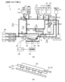
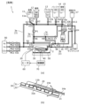
- FIG. 1 is a diagram showing a configuration of a cell culture device according to an embodiment.
- FIG. 2 is a diagram showing a configuration of a culture vessel used in the cell culture device according to the embodiment.
- FIG. 3 is a diagram showing the configuration of a container placement table in the cell culture device according to the embodiment.
- FIG. 4 is a diagram showing the movement of the container placement table when it oscillates in the cell culture device according to the embodiment.
- FIG. 5 is a diagram for explaining ON/OFF control of the magnets in the container arrangement table in the cell culture device according to the embodiment.
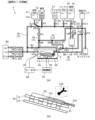
- FIG. 6A is a diagram for explaining a step of introducing air into a first liquid in the cell culture method according to the embodiment.
- FIG. 6B is a view for explaining the first liquid supplying step (cell supplying step) in the cell culture method according to the embodiment.
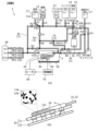
- FIG. 6C is a diagram for explaining the magnetic bead supplying step in the cell culture method according to the embodiment.
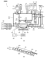
- FIG. 6D is a diagram for explaining the rocking step in the magnetic bead supplying step in the cell culture method according to the embodiment.
- FIG. 6E is a diagram for explaining the movement of the container arrangement table when the magnet is turned on in the magnetic bead supplying step in the cell culture method according to the embodiment.
- FIG. 6F is a view for explaining a second liquid discharging step in the cell culture method according to the embodiment.
- FIG. 6G is a diagram for explaining the buffer solution supplying step (washing step) in the cell culture method according to the embodiment.
- FIG. 6H is a view for explaining a buffer solution discharge step in the cell culture method according to the embodiment.
- FIG. 6I is a view for explaining a third liquid supplying step (viral vector supplying step) in the cell culture method according to the embodiment.
- FIG. 6J is a diagram for explaining a medium supplying step in the culture step in the cell culture method according to the embodiment.
- FIG. 6K is a diagram for explaining a residual liquid removing step in the culture step in the cell culture method according to the embodiment.
- FIG. 6L is a diagram for explaining a medium circulation step in the culture step in the cell culture method according to the embodiment.
- FIG. 6M is a diagram for explaining a medium discharging step at the time of medium replacement in the culture step in the cell culture method according to the embodiment.
- FIG. 6N is a diagram for explaining a medium supplying step at the time of medium replacement in the culture step in the cell culture method according to the embodiment.
- FIG. 6O is a diagram for explaining a gas exchange step in the culture step in the cell culture method according to the embodiment.
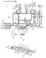
- FIG. 7 is a diagram showing a configuration of an incubation container according to the first modified example.
- FIG. 8 is a diagram for explaining an example of use of the culture vessel according to the first modified example.
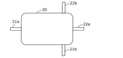
- FIG. 9 is a diagram showing the configuration of the culture vessel according to the second modification.
- FIG. 10 is a diagram for explaining an example of use of the culture vessel according to the second modification.
- FIG. 11 is a diagram showing a first modified example of the container arrangement section in the cell culture device according to the embodiment.
- FIG. 12 is a diagram showing an example of a configuration of a container arrangement section and a culture container arranged in the container arrangement section in the cell culture device according to the embodiment.
- FIG. 13 is a diagram showing a second modified example of the container arrangement section in the cell culture device according to the embodiment.
- FIG. 14 is a diagram showing the configuration of an incubation container according to the third modification.
- FIG. 15 is a diagram showing the configuration of a cell culture device according to a modified example.
- a cell culture device to generate target cells such as iPS cells from a cell mixture such as blood, and then to grow them through culturing.
- target cells such as iPS cells from a cell mixture such as blood
- hematopoietic stem cells are extracted from the blood
- iPS cells are generated from the extracted hematopoietic stem cells
- the generated iPS cells are cultured in a culture medium.
- Patent Document 1 and other publications have the problem that they are unable to respond to changes in the air composition inside the culture vessel when culturing cells in the culture vessel, resulting in low culture efficiency. As such, it is difficult to efficiently culture target cells using a cell culture device with conventional methods.
- the inventors of the present application conducted extensive research into these issues and discovered that the target cells can be cultured efficiently by supplying gas directly to the culture vessel.
- one aspect of the cell culture device disclosed herein includes a gas supply device that supplies gas to a gas supply line connected to a culture vessel, and the culture vessel is supplied with a liquid containing first cells and a culture medium for culturing second cells generated from the first cells.
- gas can be supplied directly to the culture vessel by the gas supply device.
- This allows gas to be quickly supplied to the culture vessel in response to changes in the air composition inside the culture vessel, thereby maintaining the atmosphere inside the culture vessel at a suitable level.
- the culture atmosphere inside the culture vessel when culturing second cells can be made to be an optimal environment for culture.
- the same culture vessel can be used to extract first cells and to culture second cells obtained from the first cells. Therefore, the target second cells can be efficiently cultured from the first cells.
- the culture vessel is connected to a supply path for supplying the liquid containing the first cells and the culture medium to the culture vessel, and a discharge path for discharging the vessel liquid present in the culture vessel, the liquid containing the first cells is supplied from the cell vessel to the culture vessel, the culture medium is supplied from the culture medium vessel to the culture vessel, and the cell vessel, the culture medium vessel, and the culture vessel form a closed space when the cell vessel and the culture medium vessel are connected to the supply path and the discharge path.
- one end of a gas exhaust passage provided separately from the gas supply passage is connected to the culture vessel, and the other end of the gas exhaust passage is configured to be openable.
- the old gas inside the culture vessel can be pushed out by the new gas being supplied to the culture vessel.
- the gas inside the culture vessel can be replaced. This allows the target second cells to be cultured more efficiently.
- the culture vessel is provided with a supply port connected to the gas supply path and a discharge port connected to the one end of the gas discharge path, which are separate from each other, and the supply port and the discharge port are preferably provided at opposing positions across the culture vessel.
- the gas supply path may merge with a liquid supply path that supplies liquid to the culture vessel, and the liquid supply path may be part of the supply path.
- gas can be sent through the gas supply path to the liquid supply path, allowing the gas to push out any residual liquid remaining in the liquid supply path. This makes it possible to eliminate any residual liquid remaining in the liquid supply path.
- the gas supply device may supply gas to the liquid supply path, thereby flushing any liquid remaining in the liquid supply path out of the liquid supply path.
- This configuration makes it possible to push out any unnecessary residual liquid remaining in the liquid supply path and remove it from the supply path. This makes it possible to prevent the unnecessary residual liquid from seeping into the culture vessel. As a result, it is possible to prevent contamination caused by the unnecessary residual liquid.
- the gas supply device supplies gas to a liquid discharge path for discharging liquid from the culture vessel, thereby flushing liquid remaining in the liquid discharge path from the liquid discharge path, and the liquid discharge path may be a part of the discharge path.
- This configuration allows unnecessary residual liquid remaining in the discharge path to be removed from the discharge path. This makes it possible to prevent unnecessary residual liquid from entering the culture vessel during medium circulation using the discharge path, etc. As a result, it is possible to prevent contamination caused by unnecessary residual liquid.
- the gas may be supplied to the culture vessel while the culture vessel is tilted.
- This configuration allows the liquid and gas in the culture vessel to be separated, making it possible to carry out gas exchange without passing gas through the liquid in the culture vessel.
- a relief valve may be provided in the gas supply path.
- This configuration makes it possible to prevent excessive pressure from being applied to the culture vessel when gas is supplied to the gas supply path.
- the device may include a stage on which the culture vessel is placed, a heater provided on the stage, and a temperature sensor provided on the stage, and the output of the heater may be controlled according to the temperature measured by the temperature sensor.
- the output of the heater may be controlled according to the amount of gas supplied to the gas supply path and the temperature measured by the temperature sensor.
- This configuration allows the culture atmosphere inside the culture container placed on the stage to be adjusted to create an environment suitable for culture.
- a gas heater for heating the gas may be provided.
- This configuration allows gas exchange to be performed so that the gas temperature inside the culture vessel is at an optimal temperature.
- the gas heater may be provided in the gas supply path.
- the gas heater may be provided in the gas supply device.
- the gas in the culture vessel may be exchanged by supplying the gas to the culture vessel via the gas supply path using the gas supply device.
- This configuration allows the culture atmosphere in the culture vessel when culturing the second cells to be an optimal environment for culture. This allows the target second cells to be cultured efficiently.
- the gas may be a mixed gas containing nitrogen, oxygen, and carbon dioxide.
- This configuration allows the culture atmosphere in the culture container when culturing the second cells to be maintained at an optimal environment similar to that inside human tissue. This allows the target second cells to be cultured efficiently.
- the culture vessel is a vessel for culturing second cells generated from first cells, and a liquid containing a viral vector is supplied to the culture vessel to infect the first cells with the virus and generate the second cells.
- This configuration makes it possible to transform a first cell into a second cell within the culture vessel.
- the first cells may be hematopoietic stem cells
- the liquid containing the first cells may be blood
- the second cells may be iPS cells.
- This configuration makes it possible to generate iPS cells from hematopoietic stem cells extracted from blood in a culture vessel.
- the vessel is provided with a supply port through which a liquid containing the first cells from a cell vessel and a culture medium from a culture medium vessel are supplied, and a discharge port through which the vessel liquid present in the culture vessel is discharged, and the supply port and the discharge port are preferably provided separately.
- a supply port for supplying the liquid containing the first cells and the culture medium to the culture vessel, and a discharge port for discharging the vessel liquid present in the culture vessel are provided as separate ports. This makes it possible to prevent the time taken to discharge liquid from the culture vessel (when discharging liquid) from increasing. Specifically, it is possible to prevent the time taken to discharge liquid from the culture vessel when extracting the first cells from increasing, and it is also possible to prevent the time taken to discharge culture medium from the culture vessel when changing the culture medium, etc.
- the cell vessel, the medium vessel, and the culture vessel may form a closed space when the cell vessel and the medium vessel are connected to the supply port.
- the culture vessel has a shape including two short sides facing one direction and two long sides facing another direction that intersects the one direction when viewed from above, the culture vessel has a first supply port and a second supply port as the supply ports, and a first discharge port and a second discharge port as the discharge ports, the first supply port is provided on one of the two short sides of the culture vessel, the first discharge port is provided on the other of the two short sides of the culture vessel, and the second supply port and the second discharge port are provided on the other of the two short sides of the culture vessel, or are provided separately on one and the other of the two long sides of the culture vessel.
- the circulation path of the culture medium can be selected according to the volume of the culture medium inside the culture vessel. This allows the culture medium to be circulated efficiently. Therefore, it is possible to obtain a culture vessel in which the target second cells can be cultured more efficiently.
- a supply path for supplying the liquid containing the first cells and the culture medium to the culture vessel is connected to the supply port, and a discharge path for discharging the vessel liquid present in the culture vessel is connected to the discharge port, and the supply path and the discharge path are preferably provided separately.
- the supply path for supplying the liquid containing the first cells and the culture medium to the culture vessel, and the discharge path for discharging the vessel liquid present in the culture vessel are connected to the culture vessel as separate flow paths.
- the flow path of the supply channel and the discharge channel can be designed separately.
- the optimal flow path design can be performed for each of the supply channel and the discharge channel.
- the flow path diameter of the supply channel or the discharge channel can be designed according to the flow rate of the liquid flowing through the supply channel or the liquid discharged from the discharge channel, or the flow path diameter can be designed taking into account only the liquid flowing through the supply channel. This allows the liquid containing the first cells and the liquid such as the culture medium to be supplied in appropriate amounts to the culture vessel.
- the cross-sectional area of the flow path of the supply channel may be different from the cross-sectional area of the flow path of the discharge channel.
- the liquid containing the first cells and the liquid such as the medium can be efficiently supplied to the culture vessel.
- the cross-sectional area of the discharge path larger than the cross-sectional area of the supply path, the vessel liquid in the culture vessel can be efficiently discharged.
- the discharge path is provided with a filter that captures second cells contained in the culture medium discharged from the culture vessel
- the supply path includes a culture medium supply path that supplies the culture medium to the culture vessel, and the second cells captured by the filter are returned to the culture vessel by supplying the culture medium to the culture medium supply path.
- the second cells when the medium containing the second cells is discharged from the culture vessel, the second cells are captured by the filter, and when new medium is supplied to the culture vessel during medium replacement, the second cells captured by the filter can be supplied to the culture vessel together with the medium.
- each figure is a schematic diagram and is not necessarily a precise illustration. Furthermore, in each figure, the same reference numerals are used for substantially the same configuration, and duplicate explanations are omitted or simplified.
- Fig. 1 is a diagram showing the configuration of the cell culture apparatus 1 according to the embodiment.
- Fig. 2 is a diagram showing the configuration of a culture vessel 20 used in the cell culture apparatus according to the embodiment.
- Fig. 2 (a) is an external perspective view of the culture vessel 20, (b) is a top view of the culture vessel 20, and (c) is a side view of the culture vessel 20.
- Fig. 3 is a diagram showing the configuration of a container arrangement table 30 in the cell culture apparatus 1 according to the embodiment.
- Fig. 1 is a diagram showing the configuration of the cell culture apparatus 1 according to the embodiment.
- Fig. 2 is a diagram showing the configuration of a culture vessel 20 used in the cell culture apparatus according to the embodiment.
- Fig. 2 (a) is an external perspective view of the culture vessel 20
- b is a top view of the culture vessel 20
- Fig. 3 is a diagram showing the configuration of a container arrangement table 30 in the cell culture apparatus 1 according to the embodiment.
- FIG. 3 (a) is a top view of the container arrangement table 30, and (b) is a side view of the container arrangement table 30 in a tilted state.
- Fig. 4 is a diagram showing the movement of the container arrangement table 30 when it oscillates
- Fig. 5 is a diagram for explaining the ON/OFF control of the magnet 32a in the container arrangement table 30.
- the cell culture device 1 is a device for culturing target cells.
- the cell culture device 1 is a closed type cell culture device, and various containers are connected by flow paths (pipes) etc. so that the device is always in a sealed state.
- the target cells are iPS cells. Therefore, the cell culture apparatus 1 has a mechanism for culturing and growing iPS cells.
- the iPS cells are produced from hematopoietic stem cells contained in blood. Specifically, hematopoietic stem cells extracted from blood are infected with a viral vector and an iPS gene is introduced into the hematopoietic stem cells to produce iPS cells.
- the cell culture device 1 In addition to having a mechanism for culturing iPS cells, the cell culture device 1 also has a mechanism for extracting hematopoietic stem cells, the source of iPS cells, from blood, and a mechanism for imparting iPS genes to the hematopoietic stem cells. In other words, the cell culture device 1 can automatically and continuously carry out a series of steps from producing iPS cells from blood to culturing the iPS cells.
- the target cells cultured by the cell culture apparatus 1 are not limited to iPS cells.
- T cells obtained by further inducing differentiation of iPS cells cultured by the cell culture apparatus 1 may be used as the target cells.
- the cell culture apparatus 1 may have a mechanism capable of inducing differentiation of the cultured iPS cells.
- the target cells may be stem cells other than iPS cells, such as ES cells, or cells other than stem cells.
- the cell culture device 1 includes various containers, such as a cell container 11, a magnetic bead container 12, a viral vector container 13, a buffer container 14, a culture medium container 15, a waste liquid collection container 16, a cell collection container 17, and a sampling container 18.
- containers such as a cell container 11, a magnetic bead container 12, a viral vector container 13, a buffer container 14, a culture medium container 15, a waste liquid collection container 16, a cell collection container 17, and a sampling container 18.
- the cell container 11, magnetic bead container 12, viral vector container 13, buffer container 14, and medium container 15 are liquid storage containers that store a specific liquid to be supplied to the culture container 20.
- the waste liquid collection container 16, cell collection container 17, and sampling container 18 are liquid collection containers that collect liquid discharged from the culture container 20.
- liquid storage containers and liquid recovery containers are, for example, transparent bags made of transparent resin film, but are not limited to this.
- these containers may be glass or stainless steel containers.
- the cell culture device 1 has a container attachment part for attaching each of these containers.
- the container attachment part has, for example, a structure that allows the container to be hooked and held.
- These containers are replaceable, and can be attached to and detached from the container attachment part. For example, these containers may be replaced each time target cells are cultured.
- the cell container 11 is a container that contains a first liquid 11a, which is a cell mixture containing first cells.
- the cell container 11 contains blood as the first liquid 11a.
- the first liquid 11a, which is blood, contains at least hematopoietic stem cells as the first cells.
- the magnetic bead container 12 is a container that contains a second liquid 12a that contains magnetic beads.
- Magnetic beads are an example of magnetic particles, and are attracted to specific cells contained in the cell mixture.
- the magnetic beads contained in the second liquid 12a have the function of being attracted to hematopoietic stem cells contained in blood.
- the viral vector container 13 is a container that contains a third liquid 13a that contains a viral vector.
- a viral vector is a vector that contains a virus that is used to impart a specific gene to cells.
- the viral vector contained in the third liquid 13a is used to impart an iPS cell gene to hematopoietic stem cells contained in blood.
- the buffer container 14 is a container that contains a buffer liquid 14a.
- the buffer container 14 contains a cleaning liquid as the buffer liquid 14a.
- the medium container 15 is a container that contains medium 15a for culturing cells.
- the target cells are iPS cells (second cells)
- the medium container 15 contains at least medium 15a for culturing iPS cells.
- Medium 15a is a culture solution that contains nutrients and the like necessary for cell growth.
- Medium 15a may be either a natural medium or a synthetic medium.
- FIG. 1 only one medium container 15 is shown, but multiple medium containers 15 may be installed.
- multiple medium containers 15 may be installed.
- the supply state of the multiple medium containers 15 can be controlled individually by valves.
- the waste liquid collection container 16 is a container for collecting liquid that is no longer needed in the cell culture device 1.
- the waste liquid collection container 16 is supplied with the liquid that is no longer needed in the culture container 20.
- Cell collection container 17 is a container for collecting target cells.
- the target cells are iPS cells, so cultured and proliferated iPS cells are collected in cell collection container 17.
- the sampling container 18 is a container for sampling liquids, etc., within the cell culture device 1. Therefore, the liquids, etc., to be sampled are supplied to the sampling container 18.
- the cell culture device 1 further includes a culture container 20, a container placement stand 30, a control mechanism 40, a weight sensor 50, a heater 60, a control unit 70, a filter 80, and a gas supply device 90.
- the culture vessel 20, the container placement stand 30, the control mechanism 40, and the weight sensor 50 are installed in the processing chamber 2.
- the processing chamber 2 is not an airtight space, but may be a closed type processing chamber that is an airtight space.
- the processing chamber 2 has an openable cover so that the culture vessel 20 can be set on the container placement stand 30. By opening the cover of the processing chamber 2, the culture vessel 20 can be set on the container placement stand 30. It is recommended that the culture vessel 20 be replaced with a new one after culturing the target cells.
- the culture vessel 20 is a vessel for culturing cells. Cells are supplied to the culture vessel 20, and culture medium for culturing the cells is also supplied to the culture vessel 20. In other words, the culture vessel 20 contains cells and culture medium. In this embodiment, the culture vessel 20 is a vessel for culturing iPS cells (second cells) generated from hematopoietic stem cells (first cells) contained in blood. Therefore, the culture vessel 20 contains at least hematopoietic stem cells, iPS cells, and culture medium.
- the culture vessel 20 is also used for purposes other than culturing target cells.
- the culture vessel 20 is used to extract cells that are the source of target cells (hematopoietic stem cells in this embodiment), and to generate target cells (iPS cells in this embodiment) from those cells.
- the culture vessel 20 is a closed bag.
- the culture vessel 20 has a bag portion as the vessel body.
- the culture vessel 20 is, for example, a flexible transparent bag made of a transparent resin film, but is not limited to this.
- the culture vessel 20 may be made of a resin material other than a transparent resin material, may be made of a material other than a resin material, and may not be flexible.
- the culture vessel 20 may be a glass or stainless steel vessel.
- the shape of the container body of the culture vessel 20 is a thin, approximately rectangular parallelepiped. Therefore, the shape of the container body of the culture vessel 20 when viewed from above is approximately rectangular. Note that the shape of the container body of the culture vessel 20 is not limited to an approximately rectangular parallelepiped.
- the culture vessel 20 has a plurality of ports for supplying liquid or gas to the inside of the culture vessel 20 and discharging liquid or gas from the inside of the culture vessel 20.
- the culture vessel 20 has two ports. Specifically, the culture vessel 20 has two ports, a supply port 21 and a discharge port 22.
- the supply port 21 and the discharge port 22 are provided in the vessel body of the culture vessel 20.
- the supply port 21 is a supply port for supplying liquid or gas to the culture vessel 20
- the discharge port 22 is a discharge port for discharging liquid or gas from the culture vessel 20.
- the supply port 21 and the discharge port 22 are long cylindrical tubes made of hard resin, but are not limited to this.
- the supply port 21 and the discharge port 22 have the same shape and size as each other, but are not limited to this.
- the supply port 21 and the discharge port 22 are provided on the same side of the container body of the culture container 20. Specifically, the supply port 21 and the discharge port 22 are provided on one of the two opposing short sides of the container body of the culture container 20.
- the culture vessel 20 is placed on a vessel placement stand 30 in the processing chamber 2.
- the culture vessel 20 placed on the vessel placement stand 30 is connected to piping that constitutes the flow path 3.
- the supply port 21 of the culture vessel 20 is connected to the end of the supply path 3a of the flow path 3, and the discharge port 22 of the culture vessel 20 is connected to the discharge path 3b of the flow path 3.
- the supply port 21 and discharge port 22 of the culture vessel 20 are removed from the flow path 3. In this way, the culture vessel 20 is configured to be detachable from the flow path 3.
- the container placement stand 30 has a stage 31 on which the culture container 20 is placed. As will be described in detail later, the container placement stand 30 is tilted by a swinging mechanism 41. In other words, the stage 31 is tilted.
- the container placement stand 30 has not only a stage 31 but also a magnet member 32 having a magnet 32a. Therefore, the container placement stand 30 can apply a magnetic load to the culture container 20 placed on the container placement stand 30.
- the magnet member 32 has a plurality of magnets 32a and a plate-shaped support member 32b that supports the plurality of magnets 32a.
- each of the plurality of magnets 32a is a permanent magnet and applies a magnetic force.
- the plurality of magnets 32a are each shaped like a rectangular parallelepiped and are arranged parallel to each other along the short side direction of each magnet 32a. In other words, the plurality of magnets 32a are arranged in a stripe pattern.
- the plurality of magnets 32a are installed along the direction in which the stage 31 is tilted.
- the multiple magnets 32a are fixed to the flat surface of the support member 32b.
- the material and shape of the support member 32b are not particularly limited as long as they can support the multiple magnets 32a. Note that not only the magnets 32a but also the support member 32b may be permanent magnets. In other words, the entire magnet member 32 may be a permanent magnet.
- the stage 31 is provided with a through hole 31a.
- the stage 31 is provided with a plurality of through holes 31a.
- the opening shape of each of the plurality of through holes 31a is rectangular, and the through holes 31a are arranged parallel to one another along the short side direction of each through hole 31a. In other words, the plurality of through holes 31a are arranged in a stripe pattern.
- each of the plurality of magnets 32a of the magnet member 32 is inserted into each of the plurality of through holes 31a provided in the stage 31.
- the plurality of through holes 31a are provided corresponding to the plurality of magnets 32a.
- a heater 60 is provided on the stage 31. Specifically, the heater 60 is embedded in the stage 31.
- the heater 60 is a heating unit for heating the culture vessel 20 placed on the stage 31.
- the temperature of the liquid in the culture vessel 20 placed on the stage 31 can be kept at a constant temperature (e.g., 37°C).
- the heater 60 is, for example, a cassette heater, but is not limited to this.
- the stage 31 is provided with a plurality of heaters 60.
- the heaters 60 are provided between two adjacent through-holes 31a. Specifically, the heaters 60 and the through-holes 31a are arranged alternately. Therefore, the magnets 32a inserted into the through-holes 31a and the heaters 60 are arranged alternately.
- the heaters 60 are arranged in a striped pattern, similar to the through-holes 31a. Therefore, the magnets 32a and the heaters 60 are arranged in a striped pattern. This configuration makes it easy to maintain a constant temperature of the liquid in the culture vessel 20 arranged on the stage 31 and to attract the magnetized first cells (hematopoietic stem cells) by the magnets 32a.
- the ON/OFF state of the heater 60 and the output of the heater 60 can be controlled by the control unit 70.
- the control unit 70 By controlling the output of the heater 60 by the control unit 70, the heating temperature of the culture vessel 20 by the heater 60 can be adjusted.
- a temperature sensor 33 is installed on the stage 31.
- the temperature sensor 33 measures the temperature of the container liquid present in the culture container 20. Therefore, it is preferable that the temperature sensor 33 is arranged near the culture container 20 when the culture container 20 is arranged on the stage 31. Specifically, it is preferable that the temperature sensor 33 is arranged so as to be in contact with the culture container 20 arranged on the stage 31.
- the temperature sensor 33 is located below the inclination of the stage 31 when the stage 31 is tilted.
- the temperature sensor 33 is preferably provided at a position that overlaps with the position where the container liquid accumulates in the culture vessel 20 when the stage 31 is tilted, as viewed from above. This allows the temperature of the liquid in the culture vessel 20 to be measured with high accuracy even if the position of the liquid surface in the culture vessel 20 changes when the stage 31 is rocked by the rocking mechanism 41 described below.
- the temperature sensor 33 is preferably provided at a position that overlaps with each of both ends of the culture vessel 20 in the longitudinal direction. This allows the temperature of the container liquid in the culture vessel 20 to be measured even if the stage 31 is tilted to the left or right.
- the temperature sensor 33 does not have to be located near the culture vessel 20. In this case, the temperature sensor 33 can estimate the temperature of the vessel liquid in the culture vessel 20 by measuring the surface temperature of the stage 31.
- the control mechanism 40 has a rocking mechanism 41 and a moving mechanism 42.
- the control mechanism 40 is controlled by the control unit 70. Therefore, the rocking mechanism 41 and the moving mechanism 42 are controlled by the control unit 70.
- the rocking mechanism 41 and the moving mechanism 42 are composed of actuators such as a crank mechanism, a link mechanism, and a motor.
- the rocking mechanism 41 has a structure that can rock the container placement table 30. By rocking the container placement table 30 with the rocking mechanism 41, the stage 31 can be rocked. In this embodiment, the rocking mechanism 41 rocks the container placement table 30 by changing the inclination of the container placement table 30.
- the rocking mechanism 41 therefore also has a structure for changing the inclination of the container placement table 30 (stage 31). As shown in FIG. 4, the rocking mechanism 41 can tilt the container placement table 30 using point S as a fulcrum. In other words, the rocking mechanism 41 can change the inclination of the container placement table 30 like a seesaw. Note that point S is not only the fulcrum when tilting the container placement table 30, but also the fulcrum (rocking fulcrum) when rocking the container placement table 30.
- the swinging mechanism 41 can change the inclination of the container placement table 30 within a tilt angle range of ⁇ 45° (-45° ⁇ tilt angle ⁇ ⁇ 45°).
- the maximum movable range when tilting the container placement table 30 is 90°.
- the oscillating mechanism 41 can oscillate the container arrangement table 30 by changing the angle of the container arrangement table 30 so that the container arrangement table 30 reciprocates.
- the oscillating mechanism 41 can oscillate the container arrangement table 30 within a predetermined angle range based on a horizontal position (tilt angle of 0°) or can tilt the container arrangement table 30 within a predetermined angle range based on a tilted state of the container arrangement table 30.
- the angle range when oscillating the container arrangement table 30 is, for example, ⁇ 3°, ⁇ 5°, ⁇ 10°, ⁇ 16°, etc.
- the speed when oscillating the container arrangement table 30 is, for example, 0.01 to 1.0 reciprocation/second.
- the container placement stand 30 can be tilted to the left or right.
- the culture vessel 20 placed on the container placement stand 30 can also be tilted to the left or right.
- one of the two short sides of the culture vessel 20 becomes lower (or upper) or the other of the two short sides becomes lower (or upper) according to the tilt of the container placement stand 30.
- the culture vessel 20 can be tilted so that the supply port 21 and discharge port 22 side are on the lower side, or the culture vessel 20 can be tilted so that the supply port 21 and discharge port 22 side are on the upper side.
- the rocking mechanism 41 tilts and rocks the container placement table 30 by integrating the stage 31 and the magnet member 32, but this is not limited to the above.
- the rocking mechanism 41 may tilt and rock only the stage 31 of the container placement table 30.
- the moving mechanism 42 can move the magnet member 32. Specifically, the moving mechanism 42 can move the magnet member 32 so as to change the distance between the stage 31 and the magnet member 32. In other words, the moving mechanism 42 can move the magnet member 32 closer to the stage 31 or farther away from the stage 31.
- the moving mechanism 42 can move the magnet 32a so as to change the distance between the magnet 32a and the stage 31.
- the magnet 32a of the magnet member 32 is inserted into the through hole 31a of the stage 31. Therefore, the moving mechanism 42 can insert the magnet 32a into the through hole 31a of the stage 31 and remove the magnet 32a from the through hole 31a.
- the weight sensor 50 can detect the weight of the liquid in the culture vessel 20. Specifically, the weight sensor 50 detects the weight of the liquid in the culture vessel 20 by detecting the weight of the culture vessel 20 containing the liquid.
- the weight sensor 50 is installed, for example, on the vessel placement stand 30, but is not limited to this.
- the control unit 70 can control the control mechanism 40. Specifically, the control unit 70 can control the rocking mechanism 41 and the moving mechanism 42. For example, by controlling the rocking mechanism 41 with the control unit 70, it is possible to change the inclination of the container placement table 30 (stage 31) and rock the container placement table 30 (stage 31).
- the control unit 70 can also control the movement mechanism 42 to move the magnet 32a closer to the stage 31 or move the magnet 32a away from the stage 31. This makes it possible to strengthen or weaken the magnetic force on the culture vessel 20 placed on the stage 31, and therefore control the ON/OFF of the magnetic load on the culture vessel 20.
- the magnet ON state is a state in which a magnetic load is applied to the culture vessel 20
- the magnet OFF state is a state in which no magnetic load is applied to the culture vessel 20.
- the magnet ON state and the magnet OFF state are switched by changing the relative distance between the stage 31 and the magnet 32a, but this is not limited to the above.
- the magnet ON state and the magnet OFF state may be switched without changing the relative distance between the stage 31 and the magnet 32a.
- an electromagnet may be placed on the stage 31, and the magnet ON state and the magnet OFF state may be switched by switching the electromagnet ON/OFF.
- the control unit 70 can also control the heater 60. Specifically, the control unit 70 can control the ON/OFF of the heater 60, control the ON time of the heater 60, and change the output of the heater 60.
- control unit 70 is a controller that is incorporated into the cell culture device 1, but is not limited to this.
- the control unit 70 may be an external device to the cell culture device 1.
- the control unit 70 may be a controller such as a tablet terminal that can communicate with the cell culture device 1 via a wired or wireless connection.
- the culture container 20 set on the container placement table 30 and the various other containers are connected by a flow path 3 shown by a thick solid line in Figure 1.
- the flow path 3 is a pipe through which a fluid such as a liquid or gas passes.
- the culture vessel 20 set on the vessel arrangement stand 30, the flow path 3 (supply path 3a, discharge path 3b, connection path 3c, culture medium supply path 3d, etc.), and the various other vessels (cell vessel 11, magnetic bead vessel 12, viral vector vessel 13, buffer vessel 14, culture medium vessel 15, waste liquid collection vessel 16, cell collection vessel 17, sampling vessel 18) connected to the culture vessel 20 via the flow path 3 constitute a closed space, more specifically, a space that has been sealed or otherwise rendered sterile.
- unintentional minute errors such as a decrease in the airtightness of the various vessels, are included in the closed space in this disclosure.
- the flow path 3 is a flexible tube made of silicone, but is not limited to this.
- the flow path 3 may be a rigid resin or metal pipe that does not have flexibility.
- the flow path 3 is also composed of multiple tubes. Each of the multiple tubes is replaceable. For example, the used tubes may be replaced every time the culture vessel 20 is replaced after culturing the target cells.
- the flow path 3 has a supply path 3a for supplying liquid to the culture vessel 20, and a discharge path 3b for discharging the vessel liquid present in the culture vessel 20.
- the supply path 3a is connected to a supply port 21 of the culture vessel 20.
- the discharge path 3b is connected to a discharge port 22 of the culture vessel 20.
- the supply path 3a and the discharge path 3b are provided separately.
- the supply path 3a and the discharge path 3b are configured as separate flow paths.
- the supply path 3a is a flow path through which liquid supplied to the culture vessel 20 flows. Specifically, the first liquid 11a contained in the cell vessel 11, the second liquid 12a contained in the magnetic bead vessel 12, the third liquid 13a contained in the viral vector vessel 13, the buffer liquid 14a contained in the buffer vessel 14, and the culture medium 15a contained in the culture medium vessel 15 flow through the supply path 3a.
- the supply path 3a also serves as a recovery path for recovering the culture medium when circulating the culture medium in the culture vessel 20.
- the discharge path 3b is a flow path through which liquid (container liquid) in the culture vessel 20 is discharged.
- the discharge path 3b is a flow path through which liquid (container liquid) that is no longer needed in the culture vessel 20 flows.
- liquids that contain liquids first liquid 11a, second liquid 12a, third liquid 13a, buffer liquid 14a, etc.
- the culture medium discharged from the culture vessel 20 when circulating the culture medium in the culture vessel 20 flows through the discharge path 3b.
- the cross-sectional area of the flow path of the supply path 3a is the same as the cross-sectional area of the flow path of the discharge path 3b.
- the flow path diameter of the supply path 3a is the same as the flow path diameter of the discharge path 3b.
- the cross-sectional area of the flow path of the supply path 3a may be different from the cross-sectional area of the flow path of the discharge path 3b.
- the flow path diameter of the supply path 3a may be different from the flow path diameter of the discharge path 3b.
- the flow path diameter of the supply path 3a larger than the flow path diameter of the discharge path 3b, when the viscosity of the liquid (first liquid 11a, second liquid 12a, third liquid 13a, buffer liquid 14a, culture medium 15a, etc.) to be supplied to the culture vessel 20 is high, this liquid can be efficiently supplied to the culture vessel 20.
- the flow path diameter of the discharge path 3b larger than the flow path diameter of the supply path 3a, the amount of the discharge liquid when discharging the liquid can be made larger than the amount of the supply liquid when supplying the liquid, so that a large amount of the vessel liquid accumulated in the culture vessel 20 can be efficiently discharged.
- the flow path 3 further includes a connection path 3c that connects the supply path 3a and the discharge path 3b.
- the connection path 3c is used to circulate the culture medium 15a in the culture vessel 20. Specifically, when the culture medium 15a in the culture vessel 20 is circulated, the culture medium 15a in the culture vessel 20 returns to the culture vessel 20 through the discharge path 3b, the connection path 3c, and the supply path 3a.
- the flow path 3 further includes a medium supply path 3d that supplies the medium 15a to the culture vessel 20.
- the medium 15a supplied from the medium vessel 15 flows through the medium supply path 3d.
- the medium supply path 3d may be used for the flow of liquids other than the medium 15a.
- the medium supply path 3d may be a part of the supply path 3a.
- the supply path 3a, the discharge path 3b, the connection path 3c, and the culture medium supply path 3d function as liquid supply paths through which liquid flows, but are not limited to this.
- the supply path 3a, the discharge path 3b, the connection path 3c, and the culture medium supply path 3d may function as gas supply paths or gas discharge paths through which gas passes.
- liquid and gas may pass through all of the pipes that make up the flow path 3 in the cell culture device 1.
- the flow path 3 also includes a gas supply path 3e to which gas is supplied by a gas supply device 90.
- the gas supply device 90 has a function of supplying gas to the gas supply path 3e. In this embodiment, only gas flows through the gas supply path 3e. The gas supplied to the gas supply path 3e is supplied to the culture vessel 20.
- the gas supply path 3e is directly connected to the culture vessel 20.
- the gas supply path 3e merges with the liquid supply path of the flow path 3, and the gas supply path 3e is directly connected to the culture vessel 20 with a part of the liquid supply path as part of the gas supply path 3e.
- the gas supply path 3e merges with the supply path 3a.
- the gas supply path 3e and the supply path 3a are connected, and a part of the supply path 3a becomes part of the gas supply path 3e, and the gas supply path 3e is directly connected to the culture vessel 20.
- the gas supply device 90 can also supply gas to the liquid supply paths such as the supply path 3a via the gas supply path 3e.
- the gas supply path 3e is branched and includes an upper flow path connected to the culture vessel 20 via the pump P1, and a lower flow path connected to the culture vessel 20 without the pump P1.
- the upper flow path of the gas supply path 3e is connected to the supply path 3a on the side farther from the culture vessel 20 (the side closer to the liquid storage vessel such as the cell vessel 11), and the lower flow path of the gas supply path 3e is connected to the supply path 3a on the side closer to the culture vessel 20 (the side farther from the liquid storage vessel such as the cell vessel 11).
- the gas supplied to the culture vessel 20 through the gas supply path 3e is, for example, a mixed gas containing nitrogen, oxygen, and carbon dioxide. Therefore, the gas supply device 90 has a function of supplying nitrogen ( N2 gas), a function of supplying oxygen ( O2 gas), and a function of supplying carbon dioxide ( CO2 gas). Specifically, the gas supply device 90 has a nitrogen tank containing nitrogen, an oxygen tank containing oxygen, and a carbon dioxide tank containing carbon dioxide.
- the gas supply device 90 may supply oxygen, nitrogen, and carbon dioxide gases individually, rather than supplying a mixed gas of the three gases oxygen, nitrogen, and carbon dioxide, or may supply a mixed gas of two gases selected from oxygen, nitrogen, and carbon dioxide.
- the gas supply device 90 is controlled by the control unit 70.
- the carbon dioxide concentration contained in the gas inside the culture vessel 20 can be maintained at 2% to 10% (preferably 5%).
- the gas supply device 90 may also supply gas into the processing chamber 2. This allows the carbon dioxide concentration inside the processing chamber 2 to be kept constant.
- Gas supplied into the culture vessel 20 is discharged from the exhaust path 3b. That is, the exhaust path 3b functions as a gas exhaust path. Specifically, one end of the exhaust path 3b, which is a gas exhaust path, is directly connected to the exhaust port 22 of the culture vessel 20. The other end of the exhaust path 3b, which is a gas exhaust path, can be opened via the waste liquid collection container 16. That is, the other end of the exhaust path 3b, which is a gas exhaust path, can be closed or opened. By opening the other end of the exhaust path 3b, which is a gas exhaust path, the gas supplied into the culture vessel 20 is released into the atmosphere via the waste liquid collection container 16 through the exhaust path 3b.
- valves V1 to V14, valves V21 to V26, and valves V31 to V33 are installed in flow path 3.
- Valves V1 to V14, valves V21 to V26, and valves V31 to V33 are opening and closing valves that control the opening and closing of flow path 3.
- valves V1 to V14 are pinch valves
- valves V21 to V26 are solenoid valves
- valves V31 to V33 are air valves.
- Valves V1 to V6 are provided in the supply path 3a.
- Valve V1 is provided near the port of the cell container 11, and supplies the first liquid 11a contained in the cell container 11 to the supply path 3a or stops the supply of the first liquid 11a to the supply path 3a.
- Valve V2 is provided near the port of the magnetic bead container 12, and supplies the second liquid 12a contained in the magnetic bead container 12 to the supply path 3a or stops the supply of the second liquid 12a to the supply path 3a.
- Valve V3 is provided near the port of the virus vector container 13, and supplies the third liquid 13a contained in the virus vector container 13 to the supply path 3a or stops the supply of the third liquid 13a to the supply path 3a.
- Valve V4 is provided near the port of the buffer container 14, and supplies the buffer liquid 14a contained in the buffer container 14 to the supply path 3a or stops the supply of the buffer liquid 14a to the supply path 3a.
- Valve V5 is provided near the port of culture medium container 15, and supplies culture medium 15a contained in culture medium container 15 to supply path 3a or stops the supply of culture medium 15a to supply path 3a.
- Valve V6 is provided in supply path 3a between pump P1 and supply port 21 of culture vessel 20, and supplies liquid to culture vessel 20 or stops the supply of liquid to culture vessel 20.
- Valve V7 is provided in connection path 3c in flow path 3, and controls the liquid flowing in connection path 3c. Valve V7 opens when circulating the culture medium in culture vessel 20, allowing the culture medium discharged from culture vessel 20 to be returned to culture vessel 20.
- Valve V8 is provided in culture medium supply path 3d in flow path 3, and controls the liquid flowing in culture medium supply path 3d. Valve V8 opens when replacing the culture medium in culture vessel 20, allowing new culture medium to be supplied to culture vessel 20 via filter 80.
- Valves V9 to V14 are provided in the discharge path 3b.
- Valve V9 is provided near the port of the waste liquid collection container 16, and flows waste liquid into the waste liquid collection container 16 or stops collection of waste liquid into the waste liquid collection container 16.
- Valve V10 is provided between valves V9 and V11 in the discharge path 3b.
- Valve V11 is provided between valve V10 and the discharge port 22 of the culture vessel 20 in the discharge path 3b.
- Valve V11 discharges liquid or gas in the culture vessel 20 from the culture vessel 20 or stops discharge of liquid or gas in the culture vessel 20.
- Valve V12 is provided between the valve V10 and the location of the branched discharge path 3b connected to the culture vessel 20 where the medium supply path 3d is connected in the discharge path 3b connected to the culture vessel 20.
- a filter 80 is provided between the valve V12 and the culture vessel 20 in the discharge path 3b.
- the filter 80 captures cells contained in the culture medium discharged from the culture vessel 20 when the culture medium in the culture vessel 20 is replaced. Specifically, the filter 80 captures iPS cells discharged from the culture vessel 20. The cells captured by the filter 80 are returned to the culture vessel 20 by feeding the culture medium from the opposite side of the filter 80.
- the valve V13 is provided near the port of the cell collection vessel 17, and collects cultured cells in the cell collection vessel 17 or stops the collection of cells to the cell collection vessel 17.
- the valve V14 is provided near the port of the sampling vessel 18, and flows a sampling liquid into the sampling vessel 18 or stops the collection of the sampling liquid into the sampling vessel 18.
- Valves V21 to V24 are provided in the gas supply path 3e.
- Valve V21 supplies carbon dioxide from the gas supply device 90 to the gas supply path 3e and stops the supply of carbon dioxide to the gas supply path 3e.
- Valve V22 supplies oxygen from the gas supply device 90 to the gas supply path 3e and stops the supply of oxygen to the gas supply path 3e.
- Valve V23 supplies nitrogen from the gas supply device 90 to the gas supply path 3e and stops the supply of nitrogen to the gas supply path 3e.
- Valve V24 is provided in the gas supply path 3e between the gas supply device 90 and the processing chamber 2, and supplies a mixed gas of carbon dioxide, oxygen, and nitrogen to the processing chamber 2 and stops the supply of the mixed gas to the processing chamber 2.
- Valves V31 and V32 are also provided in the gas supply path 3e.
- Valve V31 is provided in the lower flow path of supply path 3a, and supplies gas to the side of supply path 3a closer to the culture vessel 20 or stops the supply of gas to supply path 3a.
- Valve V32 is provided in the upper flow path of supply path 3a, and supplies gas to the side of supply path 3a closer to the liquid storage vessel such as the cell vessel 11 or stops the supply of gas to supply path 3a. Both valves V31 and V32 are located upstream of gas supply path 3e.
- relief valves R1, R2, and R3 are provided in the gas supply path 3e in the flow path 3. This makes it possible to prevent excessive pressure from being applied to the culture vessel 20 when gas is supplied to the gas supply path 3e.
- the relief valve R1 is provided in the lower flow path of the gas supply path 3e, and the relief valve R2 is provided in the upper flow path of the gas supply path 3e.
- pumps P1, P2, and P3 are provided in the flow path 3.
- the pumps P1, P2, and P3 have the function of sucking up and sending the liquid or gas flowing in the flow path 3.
- the pump P1 is provided in the supply path 3a.
- the pump P1 controls the flow of liquid or gas flowing in the main pump flow path in the flow path 3.
- the pump P1 is provided between a liquid storage container such as the cell container 11 and the culture container 20 in the supply path 3a.
- the pump P2 is provided in the discharge path 3b.
- the pump P2 controls the flow of liquid or gas flowing in the cell collection flow path in the flow path 3.
- the pump P2 is provided between the culture container 20 and a liquid collection container such as the waste liquid collection container 16 in the discharge path 3b.
- the pump P3 controls the flow of liquid or gas flowing in the sub-pump flow path in the flow path 3.
- mass controllers MC1, MC2, and MC3 are provided in the flow path 3.
- the mass controllers MC1, MC2, and MC3 control the flow rate of gas supplied from the gas supply device 90 to the gas supply path 3e.
- the mass controller MC1 adjusts the flow rate of carbon dioxide gas
- the mass controller MC2 adjusts the flow rate of oxygen gas
- the mass controller MC3 adjusts the flow rate of nitrogen gas.
- the flow path 3 is also provided with a regulator REG.
- valves, relief valves, pumps, mass controllers, etc. are controlled by the control unit 70. This allows cells to be cultured automatically according to a predetermined cell culture protocol without manual intervention. Note that valves, relief valves, pumps, etc. other than those shown in FIG. 1 may be provided in the flow path 3.
- FIGS. 6A to 6O are diagrams for explaining a cell culture method according to an embodiment.
- (a) shows the flow of liquid or gas in the flow path 3 of the cell culture device 1 (arrows in the figure), and (b) shows the tilt direction of the container arrangement table 30 and the tilt direction of the culture container 20 arranged on the container arrangement table 30.
- the open/closed states of valves V1 to V14, valves V21 to V26, and valves V31 to V33 are appropriately controlled so that liquid or gas flows through a specified flow path.
- the culture vessel 20 is set on the vessel placement stand 30 of the processing chamber 2.
- a liquid storage vessel containing a specific liquid, such as a cell vessel 11, is also set, and an empty liquid collection vessel containing no liquid, such as a waste liquid collection vessel 16, is also set.
- gas is supplied to the cell container 11 containing blood as the first liquid 11a.
- air is supplied to the cell container 11 via the gas supply path 3e and the supply path 3a by the gas supply device 90. This makes it easier to pump out all of the first liquid 11a (blood).
- a mixed gas containing nitrogen, oxygen, and carbon dioxide ( CO2 concentration 5%) is supplied to the cell container 11 as air.
- the culture container 20 When gas is supplied to the cell container 11, as shown in (a) of FIG. 6A, the culture container 20 is tilted so that the supply port 21 side (right side in the figure) is on the bottom, but this is not limited to this. In other words, the culture container 20 does not have to be tilted. Also, in this process, the container placement table 30 is in a magnet OFF state, with the stage 31 and the magnet member 32 separated. Therefore, the culture container 20 is placed on the stage 31 and is not in contact with the magnet member 32.
- a liquid containing cells is supplied to the culture vessel 20 (cell supplying step).
- blood which is the first liquid 11a containing whole blood stem cells as the first cells, is supplied to the culture vessel 20.
- the first liquid 11a is supplied from the cell vessel 11 to the culture vessel 20 via the supply path 3a by the pump P1.
- the first liquid 11a is supplied to the culture vessel 20 via the supply port 21.
- the culture vessel 20 is tilted so that the supply port 21 side (right side in the figure) is on the bottom. This allows the first liquid 11a to collect on the supply port 21 side of the culture vessel 20.
- the container placement stand 30 is oscillated by the oscillating mechanism 41.
- the container placement stand 30 (culture vessel 20) is oscillated within an angle range of 10° ⁇ 3° at a speed of 0.1 round trips per second.
- the culture vessel 20 placed on the container placement stand 30 can be oscillated and rocked. This makes it possible to stir the first liquid 11a contained in the culture vessel 20.
- the gas supply device 90 may send gas into the supply passage 3a via the gas supply passage 3e, so that the first liquid 11a remaining in the supply passage 3a can be returned to the cell vessel 11 or sent to the culture vessel 20.
- This allows unnecessary residual liquid of the first liquid 11a remaining in the supply passage 3a to be pushed out and removed from the supply passage 3a. Therefore, it is possible to prevent unnecessary residual liquid from entering the culture vessel 20 when supplying liquid to the culture vessel 20 in the next process or later. As a result, it is possible to prevent contamination caused by unnecessary residual liquid.
- the gas sent to the supply passage 3a may be a mixed gas of three gases, nitrogen, oxygen, and carbon dioxide, or a gas containing only one or two of nitrogen, oxygen, and carbon dioxide. In this way, not only liquid but also gas flows through the supply passage 3a. In other words, the supply passage 3a serves as both a liquid supply passage and a gas supply passage.
- the second liquid 12a containing magnetic beads is supplied to the culture vessel 20 (magnetic bead supplying step). Specifically, the second liquid 12a is supplied from the magnetic bead container 12 to the culture vessel 20 via the supply path 3a by the pump P1. As shown in (b) of FIG. 6C, in this step, the second liquid 12a containing magnetic beads 12b is supplied to the culture vessel 20 via the supply port 21.
- the magnetic beads 12b are adsorbed to the first cells (hematopoietic stem cells) contained in the first liquid 11a. That is, by this process, the first liquid 11a containing the first cells with the magnetic beads 12b attached thereto is contained in the culture vessel 20. That is, the first cells contained in the first liquid 11a in the culture vessel 20 can be magnetized by the magnetic beads 12b. Specifically, a mixed liquid 12c in which the first liquid 11a (blood) and the second liquid 12a are mixed is present in the culture vessel 20, and the first cells with the magnetic beads 12b attached thereto are contained in this mixed liquid 12c.
- the second liquid 12a When the second liquid 12a is supplied to the culture vessel 20, if there is no air in the magnetic bead vessel 12, it is preferable to supply air to the magnetic bead vessel 12 via the gas supply path 3e and the supply path 3a by the gas supply device 90. This makes it possible to pump out all of the second liquid 12a.
- a mixed gas containing nitrogen, oxygen, and carbon dioxide ( CO2 concentration 5%) is supplied to the magnetic bead vessel 12 as air.
- the container placement table 30 is swung to oscillate the culture container 20.
- the oscillating mechanism 41 oscillates the container placement table 30 (stage 31) in an angle range smaller than the angle of inclination of the container placement table 30 (stage 31) inclined relative to the horizontal direction.
- the oscillating mechanism 41 tilts the culture container 20 so that the supply port 21 side (right side in the figure) is on the upper side, thereby collecting the mixed liquid 12c on the side opposite the supply port 21 side, and the container placement table 30 is swung for one hour at an angle range of 10° ⁇ 5° and at a speed of 0.1 round trips/second.
- the mixed liquid 12c containing the first liquid 11a and the second liquid 12a can be stirred, and as shown in FIG. 6D (b), the adsorption reaction between the first cells 11b (hematopoietic stem cells) and the magnetic beads 12b in the mixed liquid 12c can be promoted.
- the mixed liquid 12c in the culture container 20 can be stirred, and the first cells 11b and air can be mixed together to make them uniform.
- the culture vessel 20 is tilted and the magnet is turned on. Specifically, after the rocking of the vessel arrangement table 30 is stopped, the magnet member 32 is moved closer to the stage 31 by the movement mechanism 42 without changing the tilt of the vessel arrangement table 30 (tilt angle 10°), thereby turning on the magnet.
- the container placement stand 30 (stage 31) is tilted relative to the horizontal direction. Therefore, the magnet 32a starts sucking in the first cells 11b with the culture container 20 placed on the stage 31 tilted.
- the mixed liquid 12c can be brought to the edge of the culture container 20, and the mixed liquid 12c containing the first cells 11b can be brought to the position where the magnet 32a is present.
- the first cells 11b contained in the mixed liquid 12c can be sucked in by the magnet 32a and easily extracted.
- the mixed liquid 12c containing the first cells 11b attached to the magnetic beads is discharged from the culture vessel 20 while the first cells 11b are attracted by the magnet 32a.
- the liquid in the culture vessel 20 is discharged while the first cells 11b are attracted by the magnet 32a.
- the mixed liquid 12c is discharged from the culture vessel 20 through the discharge port 22 and the discharge path 3b of the culture vessel 20 by the pump P2, and the discharged mixed liquid 12c is collected in the waste liquid collection container 16.
- the first cells 11b that remain attracted to the magnet 32a are not discharged from the culture vessel 20 but remain in the culture vessel 20.
- the liquid (mixed liquid 12c) containing the first cells 11b with the magnetic beads attached is drawn into the culture vessel 20 by the magnet 32a, and the liquid (mixed liquid 12c) is discharged from the culture vessel 20. This allows the first cells 11b to be extracted into the culture vessel 20.
- the extraction process for extracting the first cells 11b may not be limited to the step in FIG. 6F, but may also include two previous steps, the step of supplying magnetic beads to the culture vessel 20 (step in FIG. 6C) and the rocking step (step in FIG. 6D), in addition to the step in FIG. 6F.
- the container placement stand 30 (stage 31) is tilted. In other words, it is preferable to extract the first cells 11b while the culture vessel 20 is tilted. This makes it possible to collect the mixed liquid 12c in a part of the culture vessel 20 even if the amount of the mixed liquid 12c in the culture vessel 20 is small. Therefore, it is possible to easily extract the first cells 11b contained in the mixed liquid 12c.
- the culture vessel 20 is tilted so that the discharge port 22 side (right side in the figure) is on the bottom side. This allows the mixed liquid 12c to be collected on the discharge port 22 side of the culture vessel 20, so that the mixed liquid 12c can be easily discharged through the discharge port 22.
- the inclination angle of the container placement table 30 (the inclination angle of the culture vessel 20) is 10°. Note that in this process, the container placement table 30 is not rocked.
- the mixed liquid 12c remaining in the discharge path 3b may be sent to the waste liquid collection container 16 by feeding gas into the discharge path 3b via the gas supply path 3e using the gas supply device 90.
- the discharge path 3b serves as both a liquid discharge path and a gas discharge path.
- buffer solution 14a is supplied to the culture vessel 20 to wash the supply channel 3a and the inside of the culture vessel 20.
- the pump P1 supplies the buffer solution 14a from the buffer vessel 14 to the culture vessel 20 via the supply channel 3a.
- the buffer solution 14a is supplied to the culture vessel 20 via the supply port 21. Note that when the buffer solution 14a is supplied, the magnet remains ON. In other words, the buffer solution 14a is supplied to the culture vessel 20 while the magnet 32a remains close to the culture vessel 20.
- the container placement stand 30 it is preferable to rock the container placement stand 30 by the rocking mechanism 41.
- the container placement stand 30 (culture vessel 20) is rocked in an angle range of 0° ⁇ 10° at a speed of 0.1 round trips per second.
- the culture vessel 20 placed on the container placement stand 30 can be rocked and swung. This allows the inside of the culture vessel 20 to be efficiently cleaned.
- the buffer solution 14a supplied to the culture vessel 20 is discharged from the culture vessel 20.
- the buffer solution 14a is discharged from the culture vessel 20 via the discharge port 22 and discharge path 3b of the culture vessel 20 by pump P2, and the discharged buffer solution 14a is collected in the waste liquid collection container 16.
- the magnet remains ON.
- the first cell 11b is not discharged from the culture vessel 20.
- the container placement table 30 is not rocked.
- step of supplying buffer solution 14a (step in FIG. 6G) and the step of discharging buffer solution 14a (step in FIG. 6H) may be repeated multiple times until the inside of the culture vessel 20 is thoroughly washed.
- the gas supply device 90 may supply gas to the discharge path 3b, thereby sending the buffer liquid 14a remaining in the discharge path 3b to the waste liquid collection container 16. This makes it possible to remove unnecessary residual liquid remaining in the discharge path 3b from the discharge path 3b.
- a third liquid 13a containing a viral vector is supplied to the culture vessel 20 in which the extracted first cells 11b are present (viral vector supply step). Specifically, the third liquid 13a is supplied from the viral vector vessel 13 to the culture vessel 20 via the supply path 3a by the pump P1.
- the first cells 11b can be infected with the virus to generate the second cells 11c.
- the first cells 11b can be transformed into the second cells 11c within the culture vessel 20.
- the second cells 11c iPS cells, are generated from the first cells 11b, which are hematopoietic stem cells.
- the supply channel 3a may be filled with culture medium before supplying the third liquid 13a to the culture vessel 20.
- the culture vessel 20 is tilted so that the supply port 21 side (right side in the figure) is on the bottom. This allows the first liquid 11a to be collected on the supply port 21 side of the culture vessel 20.
- the tilt angle of the culture vessel 20 is 10°.
- the container placement stand 30 (culture vessel 20) is rocked within an angle range of 10° ⁇ 5° at a speed of 0.1 round trips per second.
- the culture vessel 20 placed on the container placement stand 30 can be rocked and swung. This makes it possible to stir the third liquid 13a in the culture vessel 20, thereby promoting viral infection of the first cells 11b. This makes it possible to efficiently generate the second cells 11c in the culture vessel 20.
- this step may be performed by stopping the attraction of the first cells 11b by the magnet 32a.
- the third liquid 13a may be supplied to the culture vessel 20 with the magnet OFF. This allows the first cells 11b to move freely within the third liquid 13a, further promoting viral infection of the first cells 11b.
- the magnet may be turned OFF. Specifically, the magnet member 32 is moved by the movement mechanism 42 so that the magnet 32a moves away from the stage 31.
- the gas supply device 90 may send gas into the supply channel 3a via the gas supply channel 3e, so that the third liquid 13a remaining in the supply channel 3a can be returned to the viral vector container 13 or sent to the culture vessel 20. This allows unnecessary residual liquid remaining in the supply channel 3a to be pushed out and removed from the supply channel 3a.
- the gas sent to the supply channel 3a may be a mixed gas of the three gases nitrogen, oxygen, and carbon dioxide, or a gas containing only one or two of nitrogen, oxygen, and carbon dioxide.
- culture medium 15a is supplied to culture vessel 20 (culture medium supply step). That is, culture medium 15a is supplied to culture vessel 20 containing third liquid 13a containing second cells 11c. Specifically, culture medium 15a is supplied from culture medium vessel 15 to culture vessel 20 via supply path 3a by pump P1. As shown in FIG. 6J (b), culture medium 15a is supplied to culture vessel 20 via supply port 21.
- culture medium 15a is supplied to culture vessel 20 containing third liquid 13a containing second cells 11c, so that third liquid 13a and culture medium 15a are mixed in culture vessel 20.
- culture vessel 20 contains culture medium 15c containing third liquid 13a as a mixed liquid.
- This culture medium 15c contains second cells 11c.
- second cells 11c in culture vessel 20 grow through cell division.
- second cells 11c generated in culture vessel 20 from extracted first cells 11b can be cultured in culture vessel 20.
- extraction of first cells 11b that are the source of second cells 11c and cultivation of second cells 11c generated from first cells 11b can be performed in one and the same culture vessel 20.
- extraction of hematopoietic stem cells from blood and cultivation of iPS cells, which are target cells generated from hematopoietic stem cells are performed in one and the same culture vessel 20.
- the supply of culture medium 15a to the culture vessel 20 should be performed in accordance with the cell division cycle of the second cells 11c.
- the inclination of the culture vessel 20 should be gradually reduced from the inclined state according to the amount of culture medium 15a in the culture vessel 20.
- the inclination of the container arrangement stand 30 should be gradually reduced so that the culture vessel 20 approaches a flat state. This allows optimal culture according to the amount of culture medium 15a in the culture vessel 20 when culturing the second cells 11c. It is preferable that the culture vessel 20 is flat in the final stage.
- the inclination of the culture vessel 20 may be controlled according to the weight of the culture medium 15a in the culture vessel 20 detected by the weight sensor 50. This allows optimal culture to be performed according to the liquid volume of the culture medium 15a in the culture vessel 20.
- the culture vessel 20 is tilted so that the supply port 21 side (right side in the figure) is on the bottom. This allows the culture medium 15a to be collected on the supply port 21 side of the culture vessel 20. This allows the second cells 11c to be cultured efficiently even if there is only a small amount of culture medium 15a in the culture vessel 20 when culturing the second cells 11c.
- the tilt angle of the culture vessel 20 is 10°.
- the container placement table 30 may be swung by the swinging mechanism 41.
- the swinging mechanism 41 may swing the container placement table 30 (stage 31) in an angle range smaller than the angle of inclination of the container placement table 30 (stage 31) inclined relative to the horizontal direction.
- the container placement table 30 (culture container 20) is swung in an angle range of 10° ⁇ 5° at a speed of 0.1 round trips per second.
- the culture container 20 placed on the container placement table 30 can be swung and rocked. This allows the culture medium 15a in the culture container 20 to be shaken and agitated, so that the second cells 11c contained in the culture medium 15a can be mixed with the air to be made uniform. This allows the second cells 11c to be cultured more efficiently.
- the heater 60 it is advisable to turn on the heater 60 and maintain the temperature of the culture medium 15c in the culture vessel 20 at a constant temperature (e.g., 37°C). In this case, it is advisable to control the output of the heater 60 according to the weight of the liquid in the culture vessel 20 or the inclination of the stage 31 detected by the weight sensor 50. This allows the temperature of the culture medium 15c in the culture vessel 20 to be adjusted to an optimal temperature.
- gas is fed into the supply path 3a via the gas supply path 3e by the gas supply device 90, thereby sending the medium 15a remaining in the supply path 3a to the culture vessel 20.
- the gas fed into the supply path 3a may be a mixed gas of three gases, nitrogen, oxygen, and carbon dioxide, or a gas containing only one or two of nitrogen, oxygen, and carbon dioxide.
- the medium 15a remaining in the supply path 3a can be pushed out, and a predetermined amount of medium 15a can be sent to the culture vessel 20.
- unnecessary medium 15a remaining in the supply path 3a can be eliminated.
- the medium 15a remaining in the supply path 3a may be returned to the medium container 15 instead of being pushed out into the culture container 20. In this case as well, it is possible to eliminate unnecessary medium 15a remaining in the supply path 3a.
- the medium 15a supplied to the medium container 15 is circulated (circulation process).
- the process of circulating the medium 15a is also included in the culture process.
- the pump P2 circulates the medium 15c in the culture container 20 so that the medium 15c returns to the culture container 20 by passing through the discharge path 3b, the connection path 3c, and the supply path 3a in this order.
- the medium 15c can be stirred and mixed by circulating the medium 15c so that it passes through the inside and outside of the culture container 20 using the supply path 3a, the discharge path 3b, and the connection path 3c. This allows the second cell 11c to be cultured uniformly.
- the discharge path 3b first discharge path
- the medium 15c in the culture vessel 20 is discharged from the discharge port 22, and the discharged medium 15c is supplied to the culture vessel 20 from the supply port 21, thereby circulating the medium 15c.
- the culture vessel 20 when circulating the culture medium 15c, it is advisable to tilt the culture vessel 20. In other words, it is advisable to circulate the culture medium 15c while tilting the stage 31 on which the culture vessel 20 is placed.
- the culture vessel 20 is tilted so that the supply port 21 side (the right side in the figure) is on the upper side.
- the tilt angle of the culture vessel 20 is 30°. In this way, by circulating the culture medium 15c while the culture vessel 20 is tilted, the culture medium 15c can be circulated efficiently even if the amount of culture medium 15c in the culture vessel 20 is small.
- the container placement table 30 (culture vessel 20) is rocked within an angle range of 30° ⁇ 16° at a speed of 0.05 round trips/second for one minute every 30 minutes, four times.
- the culture vessel 20 placed on the container placement table 30 can be rocked and rocked. This allows the culture medium 15a to be circulated while being stirred, so that the culture medium 15c can be mixed efficiently. This allows the second cells 11c to be generated efficiently.
- the medium 15c changes in quality due to metabolites and the like secreted from the second cells 11c. For this reason, it is advisable to replace the medium 15c with new medium at an appropriate time during the culture period.
- the medium 15c is discharged.
- the pump P2 discharges the medium 15c from the culture vessel 20 through the discharge path 3b, and the discharged medium 15c is collected in the waste liquid collection vessel 16.
- the medium 15c contains the target second cells 11c, but it is necessary to prevent the second cells 11c from being discarded in the waste liquid collection vessel 16. Therefore, in this embodiment, when the medium 15c in the culture vessel 20 is discharged, the medium 15c is made to pass through the discharge path 3b (second discharge path) in which the filter 80 is provided.
- the filter 80 captures the second cells 11c contained in the medium 15c discharged from the culture vessel 20. As a result, by discharging the medium 15c in the culture vessel 20, the second cells 11c contained in the medium 15c are captured by the filter 80.
- the culture vessel 20 When the culture medium 15c is discharged, the culture vessel 20 is tilted. Specifically, as shown in FIG. 6M (b), the culture vessel 20 is tilted so that the discharge port 22 side (the right side in the figure) is on the bottom.
- new medium 15a is supplied to the culture vessel 20.
- the medium 15a is supplied to the culture vessel 20 via a medium supply path 3d dedicated to supplying the medium 15a to the culture vessel 20.
- the pump P1 supplies new medium 15a from the medium vessel 15 to the culture vessel 20 through the supply path 3a, the connection path 3c, and the medium supply path 3d in this order.
- the second cells 11c captured by the filter 80 are returned to the culture vessel 20 by supplying the medium 15a to the medium supply path 3d.
- the second cells 11c when the medium 15c containing the second cells 11c is discharged from the culture vessel 20, the second cells 11c are captured by the filter 80, and when new medium 15a is supplied to the culture vessel 20 during medium replacement, the second cells 11c captured by the filter 80 are supplied to the culture vessel together with the medium 15a.
- This allows the second cells 11c to be cultured in new medium 15a without being discarded. In other words, the culture of the second cells 11c can be continued.
- the second cells 11c By replacing the old medium 15c with new medium 15a in this manner, the second cells 11c can be cultured efficiently, thereby shortening the proliferation time of the second cells 11c.
- the culture vessel 20 When supplying new culture medium 15a, the culture vessel 20 is tilted. For example, as shown in FIG. 6N(b), the culture vessel 20 is tilted so that the supply port 21 side (right side in the figure) is on the bottom, but this is not limited to this.
- the medium replacement process (steps in FIG. 6M and FIG. 6N) may be performed two or more times instead of just once.
- the gas supply device 90 may send gas into the supply path 3a, the connection path 3c, and the culture medium supply path 3d, so that the culture medium 15a remaining in the supply path 3a, the connection path 3c, and the culture medium supply path 3d can be returned to the culture medium container 15 or sent to the culture vessel 20.
- the gas supply device 90 may send gas into the discharge path 3b via the gas supply path 3e, so that the culture medium 15a remaining in the discharge path 3b can be sent to the waste liquid collection container 16. This makes it possible to eliminate residual liquid from the discharge path 3b.
- the gas in the culture vessel 20 may be exchanged.
- gas is supplied to the culture vessel 20 by the gas supply device 90 via the gas supply path 3e and the supply path 3a.
- the gas supply path 3e is directly connected to the culture vessel 20 together with the supply path 3a, so that gas can be efficiently supplied to the culture vessel 20.
- one end of exhaust channel 3b which serves as a gas exhaust channel, is directly connected to culture vessel 20, and the other end of exhaust channel 3b, which serves as a gas exhaust channel, is open via waste liquid collection vessel 16.
- This allows old gas in culture vessel 20 to be pushed out by newly supplied gas to culture vessel 20. In other words, gas in culture vessel 20 can be easily replaced.
- the culture atmosphere inside the culture vessel 20 when culturing the second cells 11c can be made into an optimal culture environment. Therefore, the second cells 11c can be cultured even more efficiently.
- the gas supplied to the culture vessel 20 may be a mixed gas containing nitrogen, oxygen, and carbon dioxide (e.g., CO2 concentration 5%), similar to air.
- CO2 concentration 5% a mixed gas containing nitrogen, oxygen, and carbon dioxide (e.g., CO2 concentration 5%), similar to air.
- the gas supply path 3e is branched into the upper and lower sides of the pump P1, but when performing gas exchange, it is preferable to supply gas to the culture vessel 20 via the lower gas supply path 3e, as shown in FIG. 6O (a).
- the culture vessel 20 arranged on the stage 31 is heated by the heater 60.
- the output of the heater 60 is controlled according to the temperature measured by the temperature sensor 33.
- the output of the heater 60 may be controlled according to the amount of gas supplied to the gas supply path 3e and the temperature measured by the temperature sensor 33. In other words, the output of the heater 60 may be controlled according to not only the temperature but also the amount of gas. This makes it possible to adjust the culture atmosphere in the culture vessel 20 arranged on the stage 31 to an environment suitable for culture.
- the newly supplied gas when gas exchange is performed, the newly supplied gas may be heated by a gas heater.
- the gas heater may be provided in the middle of the gas supply path 3e, or may be provided in the gas supply device 90. In this way, by heating the newly supplied gas, gas exchange can be performed so that the temperature of the gas in the culture vessel 20 becomes an optimal temperature. This makes it possible to make the culture atmosphere in the culture vessel 20 when culturing the second cells 11c an optimal environment for culture. Therefore, the second cells 11c can be cultured efficiently.
- the second cells 11c which are target cells, can be cultured and grown.
- the cultured second cells 11c are then collected in the cell collection container 17.
- the second cells 11c may be collected by being attracted by the magnets 32a.
- the magnets 32a may be controlled so as to attract the cultured second cells 11c using a greater number of magnets 32a than some of the magnets 32a.
- the cultured second cells 11c may be attracted using all of the magnets 32a. In this way, even if a large amount of the second cells 11c grows due to culture, the large amount of the second cells 11c can be easily attracted by the magnets 32a. Therefore, the second cells 11c can be efficiently collected.
- the cell culture method includes an extraction step of extracting the first cells 11b into the culture vessel 20 by discharging the first liquid 11a from the culture vessel 20 in a state in which the first cells 11b are attracted by the magnet 32a to the culture vessel 20, which contains the first liquid 11a containing the first cells 11b with the magnetic beads 12b attached thereto, and a culture step of culturing the second cells 11c generated in the culture vessel 20 based on the extracted first cells 11b by supplying the culture medium 15a to the culture vessel 20.
- the first cells 11b that are the source of the second cells 11c are extracted in a culture vessel 20 for culturing the target second cells 11c.
- the process of extracting the first cells 11b from the first liquid 11a and the process of culturing the second cells 11c obtained from the first cells 11b are carried out in the same culture vessel 20. This allows the target second cells 11c to be cultured efficiently.
- the first aspect of the cell culture device includes a cell container 11 containing a first liquid 11a including a first cell 11b, a culture medium container 15 containing a culture medium 15a, and a culture container 20 containing a culture medium 15a for culturing a second cell 11c.
- the cell culture device 1 is configured to extract the first cell 11b into the culture container 20 by discharging the first liquid 11a from the culture container 20 in a state in which the first cell 11b is attracted by the magnet 32a to the culture container 20 containing the first liquid 11a including the first cell 11b to which the magnetic beads 12b are attached, and to culture the second cell 11c generated in the culture container 20 based on the extracted first cell 11b in the culture container 20.
- the first cells 11b that are the source of the second cells 11c are extracted in the culture vessel 20 in which the target second cells 11c are cultured.
- the extraction of the first cells 11b from the first liquid 11a and the culture of the second cells 11c obtained from the first cells 11b are performed in the same culture vessel 20. This allows the target second cells 11c to be cultured efficiently.
- the second aspect of the cell culture device includes a cell container 11 containing a first liquid 11a including a first cell 11b, a culture medium container 15 containing a culture medium 15a, a culture container 20 for culturing a second cell 11c generated from the first cell 11b, a supply path 3a for supplying the first liquid 11a and the culture medium 15a to the culture container 20, and a discharge path 3b for discharging the container liquid present in the culture container 20.
- the supply path 3a and the discharge path 3b are provided separately.
- a supply port 21 connected to the supply path 3a and a discharge port 22 connected to the discharge path 3b are provided separately.
- the supply path 3a for supplying the first liquid 11a and the culture medium 15a to the culture vessel 20 and the discharge path 3b for discharging the container liquid present in the culture vessel 20 are provided as separate flow paths. Also, in the culture vessel 20, the supply port 21 for supplying the first liquid 11a and the culture medium 15a to the culture vessel 20 and the discharge port 22 for discharging the container liquid present in the culture vessel 20 are provided as separate ports. This makes it possible to prevent the time required for discharging the liquid from the culture vessel 20 (discharging the liquid) from increasing.
- the flow paths of the supply path 3a and the discharge path 3b can be designed separately.
- the optimal flow path design can be performed for each of the supply path 3a and the discharge path 3b.
- the flow path diameter, etc. of the supply path 3a or the discharge path 3b can be designed according to the flow rate of the liquid flowing through the supply path 3a or the liquid discharged from the discharge path 3b, or the flow path diameter can be designed taking into account only the liquid flowing through the supply path 3a. This allows the first liquid 11a, the culture medium 15a, and other liquids to be supplied to the culture vessel in appropriate amounts.
- the target second cells 11c can be efficiently cultured even in a closed cell culture device 1.
- the third aspect of the cell culture device includes a stage 31 on which a culture container 20 for culturing a second cell 11c generated from a first cell 11b is placed, and a rocking mechanism 41 for rocking the stage 31.
- the culture vessel 20 can be tilted by changing the inclination of the stage 31 on which the culture vessel 20 containing the culture medium 15a is placed. This allows the culture medium 15a to be collected in a part of the culture vessel 20, so that even if there is a small amount of culture medium 15a in the culture vessel 20 when culturing the second cell 11c, the target second cell 11c can be efficiently cultured. It is also possible to appropriately change the inclination of the stage 31 for other purposes. For example, the inclination of the stage 31 can be changed to an appropriate inclination angle for each of the cases of supplying liquid to the culture vessel 20, discharging liquid from the culture vessel 20, and exchanging gas within the culture vessel 20.
- the culture vessel 20 can be rocked by rocking the stage 31 on which the culture vessel 20 is placed. This allows the liquid in the culture vessel 20 to be stirred. This allows the first cells 11b to be efficiently extracted from the first liquid 11a in the extraction process, and allows the second cells 11c to be efficiently cultured in the culture process.
- the fulcrum (point S) for oscillating the stage 31 is preferably located on the side of the supply path 3a and the discharge path 3b that has more flow paths.
- the fourth aspect of the cell culture device includes a container placement stand 30 on which a culture container 20 for culturing a second cell 11c generated from a first cell 11b is placed.
- the container placement stand 30 has a stage 31 on which the culture container 20 is placed, and a magnet 32a.
- the culture container 20 Prior to culturing the second cell 11c, the culture container 20 contains a first liquid 11a containing the first cell 11b with magnetic beads 12b attached thereto.
- first cells 11b that are the source of second cells 11c can be extracted in culture vessel 20 for culturing second cells 11c.
- the process of extracting first cells 11b from first liquid 11a and the process of culturing second cells 11c obtained from first cells 11b can be carried out in the same culture vessel 20. This makes it possible to efficiently culture target second cells 11c even in a closed cell culture device 1.
- the fifth aspect of the cell culture device includes a gas supply line 3e connected to the culture vessel 20 and a gas supply device 90 that supplies gas to the gas supply line 3e.
- the gas supply line 3e is directly connected to the culture vessel 20.
- gas can be supplied directly to the culture vessel 20 by the gas supply device 90.
- This allows gas to be quickly supplied to the culture vessel 20 in response to changes in the air composition within the culture vessel 20, and the atmosphere within the culture vessel 20 can be maintained at a suitable environment.
- the culture atmosphere within the culture vessel 20 when culturing the second cells 11c can be made to be an optimal environment for culture. Therefore, the target second cells 11c can be cultured efficiently.
- the culture vessel 20 is provided with one supply port 21 and one discharge port 22, but this is not limited to this.
- the culture vessel 20 may be provided with two supply ports, a first supply port 21a and a second supply port 21b, and two discharge ports, a first discharge port 22a and a second discharge port 22b.
- the first supply port 21a, the second supply port 21b, the first discharge port 22a, and the second discharge port 22b are provided separately.
- the first supply port 21a is provided on one of the two short sides of the vessel body of the culture vessel 20
- the first discharge port 22a, the second supply port 21b, and the second discharge port 22b are provided on the other of the two short sides of the vessel body of the culture vessel 20.
- the circulation path for the culture medium 15c can be selected according to the volume of the culture medium 15c in the culture vessel 20.
- the medium 15c can be circulated along the long side of the medium 15c. This allows the medium 15c to be circulated efficiently.
- the configuration is not limited to that shown in FIG. 7.
- the first supply port 21a may be provided on one of the two short sides of the vessel body of the culture vessel 20
- the first discharge port 22a may be provided on the other of the two short sides of the culture vessel 20
- the second supply port 21b and the second discharge port 22b may be provided separately on one and the other of the two long sides of the vessel body of the culture vessel 20.
- the circulation path for the culture medium 15c can be selected according to the amount of the culture medium 15c in the culture vessel 20.
- the medium 15c can be circulated along the long side of the medium 15c according to the amount of medium 15c in the culture vessel 20. This allows the medium 15c to be circulated efficiently.
- the culture medium 15c may be circulated not only using the first supply port 21a and the first discharge port 22a, but also using the second supply port 21b and the second discharge port 22b.
- FIG. 11 is a diagram showing a first modified example of the vessel placement stand 30A.
- (a) is a top view
- (b) is a cross-sectional view taken along line b-b in (a).
- the container placement stand 30A has a stage 31, a magnet member 32, and a pressing plate 34.
- the pressing plate 34 has the function of pressing the culture vessel 20 placed on the stage 31 against the stage 31.
- the container placement stand 30A has four pressing plates 34 arranged in a striped pattern with gaps between them. The entire culture vessel 20 is pressed down by these four pressing plates 34.
- the culture vessel 20 can be pressed evenly against the stage 31, so that the second cells 11c can be cultured more efficiently.
- the culture vessel 20 can be pressed evenly against the magnet 32a, so that the magnet 32a can effectively attract the first cells 11b.
- the container placement table 30A further has an elastic body 35, and the pressing plate 34 is held by the elastic body 35.
- the elastic body 35 is, for example, a spring, and is interposed between the pressing plate 34 and the stage 31.
- This configuration allows the culture vessel 20 to be held on the stage 31 according to the expansion of the culture vessel 20. Specifically, the expansion of the culture vessel 20 placed on the stage 31 changes according to the amount of liquid supplied to the culture vessel 20.
- the pressing plate 34 is held by the elastic body 35, so that the height position of the pressing plate 34 is automatically adjusted according to the expansion of the culture vessel 20. This allows the culture vessel 20 to be held on the stage 31 according to the expansion of the culture vessel 20. Therefore, it is possible to prevent the pressing plate 34 from pressing the culture vessel 20 excessively, causing damage to the culture vessel 20 itself or the liquid inside the culture vessel 20.
- the multiple elastic bodies 35 shown in FIG. 11 are arranged around the culture vessel 20 placed on the stage 31.
- a pair of elastic bodies 35 is arranged on both sides of one magnet 32a in the longitudinal direction, and four rows of one magnet 32a and one pair of elastic bodies 35 are lined up.
- the pressing plate 34 is provided in a position facing the magnet 32a. This configuration allows the magnet 32a to more effectively attract the first cell 11b.
- the pressure plate 34 is made of a magnetic material.
- the pressure plate 34 functions as a magnetic core, so that the magnetic flux density passing through the culture vessel 20 can be improved. This allows the magnet 32a to attract the first cell 11b more effectively.
- FIG. 12 is a diagram showing the configuration of the container arrangement stand 30 used in the above embodiment shown in FIG. 3 and an example of the culture vessel 20 arranged on the container arrangement stand 30.
- (a) is a top view
- (b) is a cross-sectional view taken along line b-b in (a).
- the through-hole 31a in the portion corresponding to one row on the stage 31 of the container placement stand 30 in FIG. 12 may be divided into a plurality of portions, and a plurality of through-holes 31aB may be provided in the portion corresponding to one row on the stage 31B, as in the container placement stand 30B shown in FIG. 12.
- the magnets 32a in the portion corresponding to one row on the magnet member 32 may be divided into a plurality of portions, and a plurality of magnets 32aB may be provided in the portion corresponding to one row on the magnet member 32B.
- two rows of through-holes 31aB and magnets 32aB are divided into four each.
- FIG. 13 is a diagram showing the configuration of the container placement stand 30B with the culture containers 20 placed thereon.
- (a) is a top view
- (b) is a cross-sectional view taken along the line b-b in (a).
- This configuration allows the size of the through-hole 31aB of the stage 31B and the magnet 32aB inserted into this through-hole 31aB to be reduced. As a result, as shown in FIG. 13(b), even if the magnet member 32B is moved away from the stage 31B during heating by the heater 60, etc., it is possible to prevent a part of the culture vessel 20 from entering the through-hole 31aB. Therefore, the liquid in the culture vessel 20 can be appropriately heated and mixed.
- the supply port 21 and the discharge port 22 provided in the culture vessel 20 are provided on the same side of the culture vessel 20, but this is not limited thereto.
- the supply port 21 and the discharge port 22 provided in the culture vessel 20 may be provided on different sides of the culture vessel 20.
- the supply port 21 and the discharge port 22 may be provided at positions facing each other across the culture vessel 20.
- the supply port 21 is provided on one of the two opposing short sides of the culture vessel 20
- the discharge port 22 is provided on the other of the two opposing short sides of the culture vessel 20.
- the supply port 21, which is directly connected to the gas supply path 3e, and the exhaust port 22, which is directly connected to one end of the exhaust path 3b, which is a gas exhaust path, are provided in opposing positions across the culture vessel 20.
- the step of extracting the first cells 11b from the first liquid 11a is performed in the culture vessel 20, but this is not limited to the above.
- the first cells 11b may be extracted by an electromagnet column MgC1 provided in the supply path 3a.
- the first liquid 11a (blood) and the second liquid 12a (mixture of magnetic beads) are supplied to the supply path 3a, and the electromagnet column MgC1 is turned ON to adsorb the first cells 11b (hematopoietic stem cells) contained in the first liquid 11a by the electromagnet column MgC1. Thereafter, the excess first liquid 11a and the second liquid 12a are discharged from the discharge path 3b via the culture vessel 20.
- an electromagnet column MgC2 is also provided as a second electromagnet column in the discharge path 3b. This allows the cultured second cells 11c to be collected by the electromagnet column MgC2. In this way, by using two electromagnet columns, electromagnet columns MgC1 and MgC2, it is no longer necessary to extract the first cells 11b and the second cells 11c or to collect the second cells 11c using the culture vessel 20, so the container placement table 30 does not require a magnet member 32.
- the electromagnet column MgC2 needs to adsorb the cultured and multiplied second cells 11c, it is preferable that it is larger than the electromagnet column MgC1.
- the electromagnet column MgC2 that collects the second cells 11c may be applied to the above embodiment.
- iPS cells are produced from hematopoietic stem cells by using a viral vector, but this is not limited to the above. In other words, iPS cells may be produced from hematopoietic stem cells without using a viral vector. In this case, the step of supplying the third liquid 13a containing the viral vector to the culture vessel 20 in the above embodiment is not necessary.
- gas when gas is supplied to the culture vessel 20, the gas is prevented from passing through the liquid contained in the culture vessel 20, but this is not limited to the above.
- gas may be supplied to the culture vessel 20 so that the gas passes through the liquid contained in the culture vessel 20.
- gas may be supplied to the culture vessel 20 in a state in which the culture vessel 20 is tilted so that the supply port 21 of the culture vessel 20 is on the lower side.
- the liquid contained in the culture vessel 20 is a culture medium
- gas can be supplied to the culture vessel 20 so that the gas containing carbon dioxide passes through the culture medium. This makes it possible to include carbon dioxide components in the culture medium.
- the various containers used in the cell culture device 1 are replaceable.
- the cell container 11, the magnetic bead container 12, the viral vector container 13, the buffer container 14, the medium container 15, the waste liquid collection container 16, the cell collection container 17, the sampling container 18, and the culture container 20 are replaceable containers. Therefore, although these containers were components of the cell culture device 1 in the above embodiment, they do not have to be components of the cell culture device 1.
- the flow paths 3 in the cell culture device 1 are replaceable.
- the supply path 3a, the discharge path 3b, the connection path 3c, the medium supply path 3d, and the gas supply path 3e are replaceable flow paths. Therefore, although these flow paths are components of the cell culture device 1 in the above embodiment, they do not have to be components of the cell culture device 1. Note that these flow paths may be part of the various containers described above. Therefore, when replacing the various containers, these flow paths may also be replaced. For example, when replacing the culture container 20, the flow path 3 connected to the culture container may also be replaced.
- the cell culture device 1 is of a closed type, and the cell culture method is a closed system, but this is not limited to this.
- the technology disclosed herein may be applied to an open type cell culture device, or an open system cell culture method.
- the technology disclosed herein is suitable for a closed type cell culture device and a closed system cell culture method.
- the technology disclosed herein is useful as a cell culture method for culturing cells such as iPS cells, a cell culture device, and a container for use in the cell culture device.
Landscapes
- Health & Medical Sciences (AREA)
- Life Sciences & Earth Sciences (AREA)
- Engineering & Computer Science (AREA)
- Chemical & Material Sciences (AREA)
- Bioinformatics & Cheminformatics (AREA)
- Organic Chemistry (AREA)
- Wood Science & Technology (AREA)
- Zoology (AREA)
- Biotechnology (AREA)
- Genetics & Genomics (AREA)
- Biomedical Technology (AREA)
- General Engineering & Computer Science (AREA)
- General Health & Medical Sciences (AREA)
- Biochemistry (AREA)
- Microbiology (AREA)
- Sustainable Development (AREA)
- Cell Biology (AREA)
- Analytical Chemistry (AREA)
- Developmental Biology & Embryology (AREA)
- Hematology (AREA)
- Molecular Biology (AREA)
- Physics & Mathematics (AREA)
- Immunology (AREA)
- Medicinal Chemistry (AREA)
- Clinical Laboratory Science (AREA)
- Thermal Sciences (AREA)
- Transplantation (AREA)
- Virology (AREA)
- Biophysics (AREA)
- Plant Pathology (AREA)
- Apparatus Associated With Microorganisms And Enzymes (AREA)
Priority Applications (2)
| Application Number | Priority Date | Filing Date | Title |
|---|---|---|---|
| JP2024570093A JPWO2024150581A1 (https=) | 2023-01-12 | 2023-12-12 | |
| US19/247,180 US20250368942A1 (en) | 2023-01-12 | 2025-06-24 | Cell culture device and culture vessel |
Applications Claiming Priority (2)
| Application Number | Priority Date | Filing Date | Title |
|---|---|---|---|
| JP2023-003371 | 2023-01-12 | ||
| JP2023003371 | 2023-01-12 |
Related Child Applications (1)
| Application Number | Title | Priority Date | Filing Date |
|---|---|---|---|
| US19/247,180 Continuation US20250368942A1 (en) | 2023-01-12 | 2025-06-24 | Cell culture device and culture vessel |
Publications (1)
| Publication Number | Publication Date |
|---|---|
| WO2024150581A1 true WO2024150581A1 (ja) | 2024-07-18 |
Family
ID=91896684
Family Applications (1)
| Application Number | Title | Priority Date | Filing Date |
|---|---|---|---|
| PCT/JP2023/044383 Ceased WO2024150581A1 (ja) | 2023-01-12 | 2023-12-12 | 細胞培養装置及び培養容器 |
Country Status (4)
| Country | Link |
|---|---|
| US (1) | US20250368942A1 (https=) |
| JP (1) | JPWO2024150581A1 (https=) |
| TW (1) | TW202430622A (https=) |
| WO (1) | WO2024150581A1 (https=) |
Citations (4)
| Publication number | Priority date | Publication date | Assignee | Title |
|---|---|---|---|---|
| WO2018042710A1 (ja) * | 2016-08-29 | 2018-03-08 | 株式会社日立製作所 | 送液装置、それを用いた細胞培養装置及び方法 |
| WO2019176162A1 (ja) * | 2018-03-14 | 2019-09-19 | 株式会社日立製作所 | 細胞培養装置 |
| WO2020040118A1 (ja) * | 2018-08-20 | 2020-02-27 | アイ ピース, インコーポレイテッド | 細胞培養器 |
| JP2021087364A (ja) * | 2019-12-02 | 2021-06-10 | 株式会社日立製作所 | 細胞培養装置 |
-
2023
- 2023-12-12 JP JP2024570093A patent/JPWO2024150581A1/ja active Pending
- 2023-12-12 WO PCT/JP2023/044383 patent/WO2024150581A1/ja not_active Ceased
- 2023-12-15 TW TW112149060A patent/TW202430622A/zh unknown
-
2025
- 2025-06-24 US US19/247,180 patent/US20250368942A1/en active Pending
Patent Citations (4)
| Publication number | Priority date | Publication date | Assignee | Title |
|---|---|---|---|---|
| WO2018042710A1 (ja) * | 2016-08-29 | 2018-03-08 | 株式会社日立製作所 | 送液装置、それを用いた細胞培養装置及び方法 |
| WO2019176162A1 (ja) * | 2018-03-14 | 2019-09-19 | 株式会社日立製作所 | 細胞培養装置 |
| WO2020040118A1 (ja) * | 2018-08-20 | 2020-02-27 | アイ ピース, インコーポレイテッド | 細胞培養器 |
| JP2021087364A (ja) * | 2019-12-02 | 2021-06-10 | 株式会社日立製作所 | 細胞培養装置 |
Also Published As
| Publication number | Publication date |
|---|---|
| TW202430622A (zh) | 2024-08-01 |
| JPWO2024150581A1 (https=) | 2024-07-18 |
| US20250368942A1 (en) | 2025-12-04 |
Similar Documents
| Publication | Publication Date | Title |
|---|---|---|
| JP7116061B2 (ja) | バイオリアクタおよびその使用法 | |
| US10590374B2 (en) | Automatic multi-tray and multi-plate bioreactor systems for adherent cultures | |
| JP5197753B2 (ja) | 細胞培養装置及びこれを備えた大容量自動化細胞培養器 | |
| TWI576433B (zh) | Cell culture system and cell culture method | |
| JP6549985B2 (ja) | 培養装置、培養システム、及び培養方法 | |
| CN106103684A (zh) | 细胞培养方法、以及细胞培养系统 | |
| WO2007052718A1 (ja) | 細胞培養用振盪装置及び細胞培養方法の振盪培養方法 | |
| US20250290017A1 (en) | Bioreactor and methods of use thereof | |
| CN112888774A (zh) | 细胞培养系统、及使用其的细胞块的制造方法 | |
| JP6815618B1 (ja) | 培養システム及び培養方法 | |
| JP6625432B2 (ja) | 培養システム、及び培養方法 | |
| JP4928831B2 (ja) | 自動培養装置 | |
| ES2389412T3 (es) | Aparato de cultivo continuo con recipiente móvil para la selección de variantes de células filtrantes | |
| JPS6231908B2 (https=) | ||
| WO2024150581A1 (ja) | 細胞培養装置及び培養容器 | |
| WO2024150584A1 (ja) | 細胞培養装置及び培養容器 | |
| WO2024150585A1 (ja) | 培養容器及び細胞培養装置 | |
| WO2024150586A1 (ja) | 細胞培養方法、細胞培養装置及び培養容器 | |
| WO2024150583A1 (ja) | 細胞培養装置及び培養容器 | |
| JP2004089137A (ja) | 培養装置および培地交換方法 | |
| JPWO2012111684A1 (ja) | 自動細胞ハンドリングロボットにおける泡沫除去デバイス | |
| JP2007222063A (ja) | 培養装置及び培養方法 | |
| KR100761922B1 (ko) | 분말형 지지체를 이용한 세포 배양에 있어 세포 사이의 신호 조절에 의한 세포 배양방법 | |
| HK40005296A (en) | Bioreactor and methods of use thereof | |
| HK40005296B (en) | Bioreactor and methods of use thereof |
Legal Events
| Date | Code | Title | Description |
|---|---|---|---|
| 121 | Ep: the epo has been informed by wipo that ep was designated in this application |
Ref document number: 23916195 Country of ref document: EP Kind code of ref document: A1 |
|
| ENP | Entry into the national phase |
Ref document number: 2024570093 Country of ref document: JP Kind code of ref document: A |
|
| WWE | Wipo information: entry into national phase |
Ref document number: 2024570093 Country of ref document: JP |
|
| NENP | Non-entry into the national phase |
Ref country code: DE |
|
| 122 | Ep: pct application non-entry in european phase |
Ref document number: 23916195 Country of ref document: EP Kind code of ref document: A1 |