WO2024150566A1 - 二次電池用負極および二次電池 - Google Patents
二次電池用負極および二次電池 Download PDFInfo
- Publication number
- WO2024150566A1 WO2024150566A1 PCT/JP2023/043697 JP2023043697W WO2024150566A1 WO 2024150566 A1 WO2024150566 A1 WO 2024150566A1 JP 2023043697 W JP2023043697 W JP 2023043697W WO 2024150566 A1 WO2024150566 A1 WO 2024150566A1
- Authority
- WO
- WIPO (PCT)
- Prior art keywords
- negative electrode
- secondary battery
- active material
- silicon
- electrode active
- Prior art date
- Legal status (The legal status is an assumption and is not a legal conclusion. Google has not performed a legal analysis and makes no representation as to the accuracy of the status listed.)
- Ceased
Links
Images



Classifications
-
- H—ELECTRICITY
- H01—ELECTRIC ELEMENTS
- H01M—PROCESSES OR MEANS, e.g. BATTERIES, FOR THE DIRECT CONVERSION OF CHEMICAL ENERGY INTO ELECTRICAL ENERGY
- H01M4/00—Electrodes
- H01M4/02—Electrodes composed of, or comprising, active material
- H01M4/13—Electrodes for accumulators with non-aqueous electrolyte, e.g. for lithium-accumulators; Processes of manufacture thereof
- H01M4/134—Electrodes based on metals, Si or alloys
-
- H—ELECTRICITY
- H01—ELECTRIC ELEMENTS
- H01M—PROCESSES OR MEANS, e.g. BATTERIES, FOR THE DIRECT CONVERSION OF CHEMICAL ENERGY INTO ELECTRICAL ENERGY
- H01M4/00—Electrodes
- H01M4/02—Electrodes composed of, or comprising, active material
- H01M4/36—Selection of substances as active materials, active masses, active liquids
- H01M4/60—Selection of substances as active materials, active masses, active liquids of organic compounds
- H01M4/602—Polymers
-
- H—ELECTRICITY
- H01—ELECTRIC ELEMENTS
- H01M—PROCESSES OR MEANS, e.g. BATTERIES, FOR THE DIRECT CONVERSION OF CHEMICAL ENERGY INTO ELECTRICAL ENERGY
- H01M4/00—Electrodes
- H01M4/02—Electrodes composed of, or comprising, active material
- H01M4/62—Selection of inactive substances as ingredients for active masses, e.g. binders, fillers
- H01M4/624—Electric conductive fillers
- H01M4/625—Carbon or graphite
-
- H—ELECTRICITY
- H01—ELECTRIC ELEMENTS
- H01M—PROCESSES OR MEANS, e.g. BATTERIES, FOR THE DIRECT CONVERSION OF CHEMICAL ENERGY INTO ELECTRICAL ENERGY
- H01M4/00—Electrodes
- H01M4/02—Electrodes composed of, or comprising, active material
- H01M2004/026—Electrodes composed of, or comprising, active material characterised by the polarity
- H01M2004/027—Negative electrodes
-
- Y—GENERAL TAGGING OF NEW TECHNOLOGICAL DEVELOPMENTS; GENERAL TAGGING OF CROSS-SECTIONAL TECHNOLOGIES SPANNING OVER SEVERAL SECTIONS OF THE IPC; TECHNICAL SUBJECTS COVERED BY FORMER USPC CROSS-REFERENCE ART COLLECTIONS [XRACs] AND DIGESTS
- Y02—TECHNOLOGIES OR APPLICATIONS FOR MITIGATION OR ADAPTATION AGAINST CLIMATE CHANGE
- Y02E—REDUCTION OF GREENHOUSE GAS [GHG] EMISSIONS, RELATED TO ENERGY GENERATION, TRANSMISSION OR DISTRIBUTION
- Y02E60/00—Enabling technologies; Technologies with a potential or indirect contribution to GHG emissions mitigation
- Y02E60/10—Energy storage using batteries
Definitions
- This technology relates to negative electrodes for secondary batteries and secondary batteries.
- secondary batteries are being developed as a power source that is small, lightweight, and has a high energy density.
- These secondary batteries contain a positive electrode, a negative electrode (secondary battery negative electrode), and an electrolyte, and various studies are being conducted on the configuration of these secondary batteries.
- the negative electrode contains two types of negative electrode active materials as well as a binder (a polymer having an amide structural unit), and the mass ratio of the two types of negative electrode active materials is specified (see, for example, Patent Document 1).
- the first type of negative electrode active material contains a carbon material
- the second type of negative electrode active material contains a material (excluding carbon materials) that contains an element capable of absorbing and releasing lithium ions.
- a secondary battery negative electrode includes a negative electrode active material, a negative electrode binder, and a negative electrode conductive agent.
- the negative electrode active material includes a silicon-containing material
- the negative electrode binder includes an N-vinylacetamide polymer
- the negative electrode conductive agent includes a fibrous carbon material.
- the secondary battery of one embodiment of the present technology includes a positive electrode, a negative electrode, and an electrolyte, and the negative electrode has a configuration similar to that of the negative electrode for the secondary battery of one embodiment of the present technology described above.
- the "silicon-containing material” is a material that contains silicon as a constituent element
- the "N-vinylacetamide polymer” is one or both of a homopolymer of N-vinylacetamide and a copolymer of N-vinylacetamide. Details of the silicon-containing material and the N-vinylacetamide polymer will be described later.
- half-maximum width is the so-called full width at half maximum (FWHM). Details of the half-maximum width will be described later.
- the secondary battery negative electrode contains a negative electrode active material, a negative electrode binder, and a negative electrode conductor
- the negative electrode active material contains a silicon-containing material
- the negative electrode binder contains an N-vinylacetamide polymer
- the negative electrode conductor contains a fibrous carbon material
- FIG. 1 is a cross-sectional view illustrating a configuration of a negative electrode for a secondary battery according to an embodiment of the present technology.
- FIG. 2 is a diagram showing an example of the analysis results of the negative electrode conductive agent using Raman spectroscopy.
- FIG. 3 is a perspective view illustrating a configuration of a secondary battery according to an embodiment of the present technology.
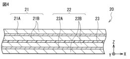
- FIG. 4 is an enlarged cross-sectional view showing the configuration of the battery element shown in FIG.
- FIG. 5 is a block diagram showing a configuration of an application example of a secondary battery.
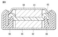
- FIG. 6 is a cross-sectional view showing the structure of a test secondary battery.
- Negative electrode for secondary battery 1-1 Structure 1-2. Physical properties 1-3. Operation 1-4. Manufacturing method 1-5. Action and effect 2. Secondary battery 2-1. Structure 2-2. Operation 2-3. Manufacturing method 2-4. Action and effect 3. Modification 4. Uses of secondary battery
- Negative electrode for secondary battery First, a negative electrode for a secondary battery (hereinafter simply referred to as a "negative electrode") according to one embodiment of the present technology will be described.
- the negative electrode described here is used in a secondary battery, which is an electrochemical device.
- the negative electrode may also be used in electrochemical devices other than secondary batteries. Examples of other electrochemical devices include primary batteries and capacitors.
- the type of electrode reaction material is not particularly limited, but specifically, it is a light metal such as an alkali metal or an alkaline earth metal.
- alkali metals include lithium, sodium, and potassium, and specific examples of alkaline earth metals include magnesium and calcium.
- the electrode reactant is lithium.
- lithium is absorbed and released in an ionic state at the negative electrode during the electrode reaction.
- Fig. 1 shows a cross-sectional structure of an example of a negative electrode, a negative electrode 1.
- the negative electrode 1 includes a negative electrode current collector 1A and a negative electrode active material layer 1B.
- the negative electrode current collector 1A has a pair of surfaces on which the negative electrode active material layer 1B is provided.
- the negative electrode current collector 1A contains a conductive material such as a metal material, and a specific example of the conductive material is copper.
- the surface of the negative electrode current collector 1A is preferably roughened. This is because the adhesion of the negative electrode active material layer 1B to the negative electrode current collector 1A is improved by utilizing the so-called anchor effect.
- the method of roughening is not particularly limited, but specifically, it is a method of forming fine particles on the surface of the metal foil using an electrolytic process. This electrolytic process is a method of forming fine particles on the surface of the metal foil using an electrolytic method in an electrolytic cell, thereby providing irregularities on the surface of the metal foil.
- the negative electrode active material layer 1B contains a negative electrode active material, a negative electrode binder, and a negative electrode conductive agent.
- the negative electrode active material layer 1B is provided on both sides of the negative electrode current collector 1A.
- the negative electrode active material layer 1B may be provided on only one side of the negative electrode current collector 1A.
- the method for forming the negative electrode active material layer 1B is not particularly limited, but specifically includes a coating method, etc.
- the negative electrode active material is a material that absorbs and releases lithium, and contains one or more types of silicon-containing materials, because silicon has an excellent lithium absorption capacity and therefore a high energy density can be obtained.
- this "silicon-containing material” is a material that contains silicon as a constituent element.
- the silicon-containing material may be silicon alone, a silicon alloy, a silicon compound, a mixture of two or more of these, or a material containing two or more of these phases.
- the structure of the silicon-containing material is not particularly limited, but may specifically be a solid solution, a eutectic (eutectic mixture), an intermetallic compound, or a mixture of two or more of these.
- elemental silicon refers to a general elemental silicon, and may contain trace amounts of impurities. In other words, the purity of elemental silicon is not necessarily limited to 100%.
- the type of silicon alloy is not particularly limited. Specifically, the silicon alloy contains, in addition to silicon, one or more of the following metal elements as constituent elements: tin, nickel, copper, iron, cobalt, manganese, zinc, indium, silver, titanium, germanium, bismuth, antimony, and chromium.
- silicon alloys are not limited to those containing one or more metal elements as constituent elements, and may contain one or more metal elements and one or more metalloid elements as constituent elements. Silicon alloys may further contain one or more nonmetallic elements as constituent elements.
- silicon compounds contain, as constituent elements other than silicon, one or more of nonmetallic elements such as oxygen and carbon. Silicon compounds may further contain, as constituent elements, one or more of the series of metallic elements contained as constituent elements in the silicon alloys described above.
- silicon alloys and silicon compounds include SiB4 , SiB6 , Mg2Si , Ni2Si , TiSi2 , MoSi2, CoSi2 , NiSi2 , CaSi2 , CrSi2, Cu5Si , FeSi2 , MnSi2, NbSi2 , TaSi2 , VSi2 , WSi2 , ZnSi2 , SiC, Si3N4 , Si2N2O , SiOx (0 ⁇ x ⁇ 2 or 0.2 ⁇ x ⁇ 1.4 ), and LiSiO.
- the compositions of the specific examples of silicon alloys and silicon compounds are not limited to those described here and can be changed as desired .
- silicon oxide SiOx
- the irreversible capacity tends to become large when the secondary battery using the negative electrode 1 is charged and discharged. Therefore, when silicon oxide is used as the silicon compound, the silicon oxide may be pre-doped with lithium. In other words, before the secondary battery is charged and discharged, the silicon oxide may be doped with lithium in advance. This is because the decrease in battery capacity due to irreversible capacity is suppressed when the secondary battery is charged and discharged.
- the crystalline state of the silicon-containing material is not particularly limited, but is preferably amorphous. More specifically, in the analysis of the silicon-containing material using X-ray diffraction (XRD), it is preferable that no crystalline peaks are detected at a diffraction angle 2 ⁇ of approximately 28° to 29°. This is because the formation of by-products that are unlikely to be involved in the electrode reaction is suppressed.
- XRD X-ray diffraction
- the surface of the silicon-containing material may be coated with carbon. This is because the electrical conductivity of the negative electrode active material is improved. In this case, the entire surface of the silicon-containing material may be coated with carbon, or only a portion of the surface of the silicon-containing material may be coated with carbon.
- the negative electrode active material may further contain one or more of the carbon materials.
- the negative electrode active material may contain both a silicon-containing material and a carbon material. This is because damage to the negative electrode active material layer 1B is suppressed while the battery capacity of the secondary battery using the negative electrode 1 is guaranteed.
- silicon-containing materials have the advantage of having a high theoretical capacity, but the drawback is that they tend to expand and contract drastically during charging and discharging.
- carbon materials have the drawback of having a low theoretical capacity, but the advantage is that they do not expand and contract easily during charging and discharging.
- carbon materials include graphitizable carbon, non-graphitizable carbon, and graphite (natural graphite and artificial graphite).
- the mixing ratio of the silicon-containing material and the carbon material is not particularly limited.
- the weight ratio M which is the ratio of the weight M1 of the silicon-containing material to the sum of the weight M1 of the silicon-containing material and the weight M2 of the carbon material, is preferably 30% by weight or more. This is because the battery capacity of the secondary battery using the negative electrode 1 is further improved while damage to the negative electrode active material layer 1B is further suppressed.
- the upper limit of the weight ratio M is not particularly limited, but it is preferable that the weight ratio M is 70% by weight or less. This is because damage to the negative electrode active material layer 1B is sufficiently and stably suppressed.
- N-vinylacetamide polymer is one or both of a homopolymer of N-vinylacetamide and a copolymer of N-vinylacetamide.
- This homopolymer of N-vinylacetamide is what is known as poly-N-vinylacetamide.
- N-vinylacetamide copolymers are compounds in which N-vinylacetamide is copolymerized with one or more types of monomers (excluding N-vinylacetamide).
- monomers excluding N-vinylacetamide.
- type of monomer but specific examples include acrylic acid, methacrylic acid, alkali metal salts of acrylates, alkaline earth metal salts of acrylates, alkali metal salts of methacrylates, and alkaline earth metal salts of methacrylates.
- alkali metal salts of acrylates include lithium acrylate, sodium acrylate, and potassium acrylate.
- alkaline earth metal salts of acrylates include calcium acrylate and magnesium acrylate.
- alkali metal salts of methacrylates include lithium methacrylate, sodium methacrylate, and potassium methacrylate.
- alkaline earth metal salts of methacrylates include calcium methacrylate and magnesium methacrylate.
- the amount of copolymerization of the monomers in the N-vinylacetamide copolymer is not particularly limited and can be set as desired.
- the N-vinylacetamide copolymer contains a copolymer of N-vinylacetamide and an alkali metal salt of acrylic acid. This is because the physical strength of the negative electrode active material layer 1B is sufficiently improved, so that the negative electrode active material layer 1B is easily maintained without being damaged even when the electrode reaction is repeated.
- the negative electrode conductive agent is a material that improves the conductivity of the negative electrode active material layer 1B and contains one or more types of fibrous carbon materials, because the negative electrode active materials are easily electrically connected to each other via the negative electrode conductive agent, and therefore a conductive network is easily formed inside the negative electrode active material layer 1B.
- the fibrous carbon material contains single-walled carbon nanotubes (SWCNTs), and that the purity of the single-walled carbon nanotubes is sufficiently high. This is because a conductive network is more easily formed inside the negative electrode active material layer 1B, and the conductivity of the negative electrode active material layer 1B is sufficiently improved.
- SWCNTs single-walled carbon nanotubes
- the average fiber diameter of the fibrous carbon material is not particularly limited, but is specifically 5 nm or less.
- the content of the negative electrode conductor (fibrous carbon material) in the negative electrode active material layer 1B is not particularly limited, but is preferably 2 wt % or less. This is because the dispersibility of the negative electrode conductor is improved in the manufacturing process of the negative electrode 1 described below (when preparing the negative electrode mixture slurry), and the stability over time of the negative electrode mixture slurry is improved.
- the negative electrode conductive agent containing the fibrous carbon material has specific physical properties that are determined by analyzing the negative electrode conductive agent using Raman spectroscopy.
- the physical properties of the negative electrode conductive agent will be described in detail later (see Figure 2).
- a specific example of the other material is another negative electrode active material, which contains one or more of the metal-based materials.
- the silicon-containing materials described above are excluded from the metal-based materials described here.
- This metallic material is a material that contains as its constituent elements one or more of metallic elements and semi-metallic elements that can form an alloy with lithium, and a specific example of the metallic element and semi-metallic element is tin.
- This metallic material may be a simple substance, an alloy, a compound, a mixture of two or more of these, or a material that contains two or more of these phases.
- styrene butadiene rubber, polyimide, or carboxymethyl cellulose salt sodium salt, potassium salt, or lithium salt
- carboxymethyl cellulose salt acts as a dispersant, allowing the carbon nanotubes to be more dispersed within the electrode, improving the maintenance of the electronic conductive network between the active materials.
- the amount of styrene butadiene rubber, polyimide, or carboxymethyl cellulose salt added is preferably 0.1 to 10% by weight, and more preferably 0.2 to 5% by weight.
- the other material is another negative electrode conductive agent
- the other negative electrode conductive agent includes one or more of the following: a carbon material, a metal material, and a conductive polymer compound.
- the above-mentioned fibrous carbon material is excluded from the other negative electrode conductive agent described here.
- Specific examples of the carbon material are particulate carbon materials such as graphite, carbon black, acetylene black, and ketjen black.
- specific examples of the carbon material are other fibrous carbon materials such as carbon fiber and carbon nanofiber.
- Fig. 2 shows an example of the analysis results of the negative electrode conductive agent using Raman spectroscopy, in which the horizontal axis indicates the Raman shift (cm -1 ) and the vertical axis indicates the Raman intensity (au (arbitrary units)).
- a Raman peak (upward convex absorption peak P) having an apex in the Raman shift range of 120 cm -1 to 300 cm -1 is detected.
- the range of the Raman shift of 120 cm -1 to 300 cm -1 is shaded, and a case in which one absorption peak P is detected is shown.
- the half-width HW of this absorption peak P is 10 cm -1 or more.
- the upper limit of the half-width HW is not particularly limited, but specifically, the half-width HW is preferably 50 cm -1 or less. As described above, this "half-width HW" is the full width at half maximum (FWHM).
- the minimum value of the Raman intensity is determined based on the baseline BL, as shown in Figure 2.
- This baseline BL is a line segment along the nearly flat Raman spectrum when the Raman spectrum is in a nearly flat state due to the Raman intensity being at a minimum (almost constant).
- the baseline BL is a line segment that extends almost along the horizontal axis.
- the reason why the physical property conditions for the negative electrode conductive agent containing the fibrous carbon material (the analysis results of the negative electrode conductive agent using Raman spectroscopy) are satisfied is because the state of the negative electrode conductive agent is optimized. In this case, a conductive network is formed using the negative electrode conductive agent even in the minute regions between the negative electrode active materials inside the negative electrode active material layer 1B, so the electronic conductivity between the negative electrode active materials is significantly improved. Furthermore, because the electrode reaction is repeated, the conductive network is more likely to be maintained without being destroyed even if the negative electrode active material layer 1B containing the silicon-containing material expands and contracts. This stably improves the conductivity of the negative electrode active material layer 1B.
- the fibrous carbon material contains single-walled carbon nanotubes. This is because the physical property conditions are more easily satisfied for the fibrous carbon material, and as described above, the conductivity of the negative electrode active material layer 1B is sufficiently improved.
- the absorption peak P is detected depends on the purity of the single-walled carbon nanotubes. Specifically, if the purity of the single-walled carbon nanotubes is sufficiently high, the absorption peak P will be detected, whereas if the purity of the single-walled carbon nanotubes is not sufficiently high, the absorption peak P will not be detected.
- a Raman spectrometer RAMAN-11 manufactured by Nanophoton Corporation can be used as an analytical device.
- the half-width HW can be calculated based on the Raman intensity of the absorption peak P, with the baseline BL as the reference.
- the negative electrode 1 is collected by dismantling the secondary battery. Then, the negative electrode 1 is washed with a washing solvent to remove the electrolyte attached to the negative electrode 1.
- the type of washing solvent is not particularly limited, but specifically, it is any one or more of organic solvents (aprotic solvents) such as carbonate ester solvents, ketone solvents, and ester solvents. If a coating remains on the surface of the negative electrode 1, the negative electrode 1 may be further washed with an aqueous solvent such as water.
- the negative electrode conductive agent contained in the negative electrode 1 is analyzed using Raman spectroscopy. This checks whether an absorption peak P (half width HW ⁇ 10 cm ⁇ 1 ) is detected.
- the procedure for checking whether or not the absorption peak P is detected may be repeated multiple times in order to improve the accuracy of detecting the absorption peak P.
- the procedure for calculating the half-width HW may be repeated multiple times, and an average value may be used as the half-width HW.
- Fig. 2 shows a case where one absorption peak P is detected.
- a composite peak may be detected.
- This composite peak is a peak in which two or more absorption peaks P are combined with each other, and has two or more apexes within the Raman shift range of 120 cm -1 to 300 cm -1 .
- two or more absorption peaks P are obtained by separating the composite peak using an existing peak separation method, and then one absorption peak P with the maximum Raman intensity (so-called peak intensity) is selected from the two or more absorption peaks P, and this one absorption peak P is used as the absorption peak P for calculating the half-width HW.
- the negative electrode 1 is manufactured by the procedure of one example of which is described below.
- an anode active material containing a silicon-containing material, an anode binder containing an N-vinylacetamide polymer, and an anode conductive agent containing a fibrous carbon material are mixed together to prepare an anode mixture.
- a fibrous carbon material that satisfies the above-mentioned physical property conditions is used.
- This solvent is an aqueous solvent such as ion-exchanged water.
- the negative electrode mixture slurry is applied to both sides of the negative electrode current collector 1A to form the negative electrode active material layer 1B.
- the negative electrode mixture slurry may be heated as necessary.
- the negative electrode active material layer 1B is compression molded using a roll press or the like.
- the negative electrode active material layer 1B may be heated, and the compression molding may be repeated multiple times.
- the negative electrode active material layer 1B is formed on both sides of the negative electrode current collector 1A, completing the negative electrode 1.
- the negative electrode 1 contains a negative electrode active material (a silicon-containing material), a negative electrode binder (an N-vinylacetamide polymer), and a negative electrode conductive agent (a fibrous carbon material), and the half-width HW of an absorption peak P detected in an analysis of the negative electrode conductive agent using Raman spectroscopy is 10 cm -1 or more.
- a negative electrode active material a silicon-containing material
- a negative electrode binder an N-vinylacetamide polymer
- a negative electrode conductive agent a fibrous carbon material
- the negative electrode active material contains a silicon-containing material
- a high energy density is obtained.
- the negative electrode binder contains an N-vinylacetamide polymer
- the physical strength of the negative electrode active material layer 1B is improved. This makes it easier for the negative electrode active material layer 1B to be maintained without being damaged even when the electrode reaction is repeated.
- the negative electrode conductor contains a fibrous carbon material, the physical property conditions for the negative electrode conductor are satisfied. This makes it easier for a conductive network to be formed using the negative electrode conductor even in the minute regions between the negative electrode active materials inside the negative electrode active material layer 1B, and makes it easier for the conductive network to be maintained without being destroyed even when the electrode reaction is repeated.
- the conductivity of the negative electrode active material layer 1B is stably improved, and the battery characteristics of a secondary battery using the negative electrode 1 are improved. Therefore, a secondary battery with excellent battery characteristics can be realized by using the negative electrode 1.
- the fibrous carbon material contains single-walled carbon nanotubes, the physical property conditions for the negative electrode conductive agent are more likely to be satisfied. This sufficiently improves the conductivity of the negative electrode active material layer 1B, resulting in greater effects.
- the negative electrode active material further contains a carbon material, the battery capacity of the secondary battery using the negative electrode 1 is guaranteed while damage to the negative electrode active material layer 1B is suppressed, resulting in even greater effects.
- the weight ratio of the silicon-containing material is 30% by weight or more, the battery capacity of the secondary battery using the negative electrode 1 is improved while damage to the negative electrode active material layer 1B is further suppressed, resulting in even greater effects.
- the secondary battery described here is a secondary battery that obtains battery capacity by utilizing the absorption and release of an electrode reactant, and is equipped with a positive electrode, a negative electrode, and an electrolyte.
- the electrode reactant is lithium.
- a secondary battery that obtains battery capacity by utilizing the absorption and release of lithium is a so-called lithium-ion secondary battery. In this lithium-ion secondary battery, lithium is absorbed and released in an ionic state.
- the charge capacity of the negative electrode is preferably greater than the discharge capacity of the positive electrode.
- the electrochemical capacity per unit area of the negative electrode is preferably greater than the electrochemical capacity per unit area of the positive electrode. This is to prevent lithium from being deposited on the surface of the negative electrode during charging.
- Fig. 3 shows a perspective view of the secondary battery
- Fig. 4 shows an enlarged cross-sectional view of the battery element 20 shown in Fig. 3.
- Fig. 3 shows a state in which the exterior film 10 and the battery element 20 are separated from each other, and the cross section of the battery element 20 taken along the XZ plane is shown by a broken line.
- Fig. 4 shows only a part of the battery element 20.
- this secondary battery includes an exterior film 10, a battery element 20, a positive electrode lead 31, a negative electrode lead 32, and sealing films 41 and 42.
- the secondary battery described here is a laminate film type secondary battery that uses a flexible or pliable exterior film 10.
- the exterior film 10 is an exterior member that houses the battery element 20, and has a bag-like structure that is sealed with the battery element 20 housed therein. As a result, the exterior film 10 houses an electrolyte together with a positive electrode 21 and a negative electrode 22, which will be described later.
- the exterior film 10 is a single film-like member that is folded in the folding direction F.
- This exterior film 10 is provided with a recessed portion 10U (a so-called deep drawn portion) for accommodating the battery element 20.
- the exterior film 10 is a three-layer laminate film in which a fusion layer, a metal layer, and a surface protection layer are laminated in this order from the inside, and when the exterior film 10 is folded, the outer peripheral edges of the opposing fusion layers are fused to each other.
- the fusion layer contains a polymer compound such as polypropylene.
- the metal layer contains a metallic material such as aluminum.
- the surface protection layer contains a polymer compound such as nylon.
- the configuration (number of layers) of the exterior film 10, which is a laminate film is not particularly limited, and may be one or two layers, or four or more layers.
- the battery element 20 is a power generating element including a positive electrode 21, a negative electrode 22, a separator 23, and an electrolyte (not shown), and is housed inside the exterior film 10.
- This battery element 20 is a so-called wound electrode body. That is, the positive electrode 21 and the negative electrode 22 are stacked on top of each other with a separator 23 interposed therebetween, and are wound around a winding axis P while facing each other through the separator 23.
- This winding axis P is a virtual axis that extends in the Y-axis direction.
- the three-dimensional shape of the battery element 20 is not particularly limited.
- the battery element 20 is flat, and therefore the shape of the cross section (cross section along the XZ plane) of the battery element 20 intersecting the winding axis P is a flat shape defined by the long axis J1 and the short axis J2.
- the long axis J1 is an imaginary axis that extends in the X-axis direction and has a length greater than the length of the short axis J2
- the short axis J2 is an imaginary axis that extends in the Z-axis direction intersecting the X-axis direction and has a length smaller than the length of the long axis J1.
- the three-dimensional shape of the battery element 20 is a flat cylindrical shape, and therefore the shape of the cross section of the battery element 20 is a flattened approximate ellipse.
- the positive electrode 21 includes a positive electrode current collector 21A and a positive electrode active material layer 21B.
- the positive electrode collector 21A has a pair of surfaces on which the positive electrode active material layer 21B is provided.
- This positive electrode collector 21A contains a conductive material such as a metal material, and a specific example of the conductive material is aluminum.
- the positive electrode active material layer 21B is provided on both sides of the positive electrode collector 21A, and contains one or more types of positive electrode active materials that absorb and release lithium.
- the positive electrode active material layer 21B may be provided on only one side of the positive electrode collector 21A on the side where the positive electrode 21 faces the negative electrode 22.
- the positive electrode active material layer 21B may further contain one or more types of other materials such as a positive electrode binder and a positive electrode conductor.
- the method of forming the positive electrode active material layer 21B is not particularly limited, but specifically includes a coating method, etc.
- the type of positive electrode active material is not particularly limited, but specifically includes lithium-containing compounds.
- This lithium-containing compound is a compound that contains one or more transition metal elements as constituent elements along with lithium, and may further contain one or more other elements as constituent elements.
- the type of other element is not particularly limited, so long as it is an element other than lithium and transition metal elements, but specifically includes elements belonging to groups 2 to 15 of the long period periodic table.
- the type of lithium-containing compound is not particularly limited, but specifically includes oxides, phosphate compounds, silicate compounds, and borate compounds.
- oxides include LiNiO2 , LiCoO2 , LiCo0.98Al0.01Mg0.01O2 , LiNi0.5Co0.2Mn0.3O2 , LiNi0.8Co0.15Al0.05O2 , LiNi0.33Co0.33Mn0.33O2 , Li1.2Mn0.52Co0.175Ni0.1O2 , Li1.15 ( Mn0.65Ni0.22Co0.13 ) O2 , and LiMn2O4 .
- phosphate compounds include LiFePO4 , LiMnPO4 , LiFe0.5Mn0.5PO4 , and LiFe0.3Mn0.7PO4 .
- the positive electrode binder contains one or more of the following materials: synthetic rubber and polymeric compounds.
- synthetic rubber include styrene-butadiene rubber, fluororubber, and ethylene-propylene-diene.
- polymeric compounds include polyvinylidene fluoride, polyimide, and carboxymethyl cellulose.
- the positive electrode conductive agent contains one or more conductive materials such as carbon materials, metal materials, and conductive polymer compounds.
- conductive materials such as carbon materials, metal materials, and conductive polymer compounds.
- Specific examples of carbon materials include graphite, carbon black, acetylene black, and ketjen black.
- the negative electrode 22 has a configuration similar to that of the negative electrode 1 described above. That is, the negative electrode 22 includes a negative electrode current collector 22A and a negative electrode active material layer 22B as shown in Fig. 4.
- the configuration of the negative electrode current collector 22A is similar to that of the negative electrode current collector 1A
- the configuration of the negative electrode active material layer 22B is similar to that of the negative electrode active material layer 1B.
- the separator 23 is an insulating porous film interposed between the positive electrode 21 and the negative electrode 22, and allows lithium ions to pass through while preventing contact (short circuit) between the positive electrode 21 and the negative electrode 22.
- the separator 23 contains a polymer compound such as polyethylene.
- the electrolyte is a liquid electrolyte that is impregnated into each of the positive electrode 21, the negative electrode 22, and the separator 23, and contains a solvent and an electrolyte salt.
- the solvent contains one or more types of non-aqueous solvents (organic solvents), and the electrolyte containing the non-aqueous solvent is a so-called non-aqueous electrolyte.
- the non-aqueous solvent is an ester or ether, and more specifically, a carbonate ester compound, a carboxylate ester compound, a lactone compound, etc. This is because the dissociation of the electrolyte salt is improved, and the mobility of the ions is also improved.
- Carbonate compounds include cyclic carbonates and chain carbonates. Specific examples of cyclic carbonates include ethylene carbonate and propylene carbonate, while specific examples of chain carbonates include dimethyl carbonate, diethyl carbonate, and ethyl methyl carbonate.
- Carboxylic acid ester compounds include chain carboxylates, and specific examples of chain carboxylates include ethyl acetate, ethyl propionate, propyl propionate, and ethyl trimethylacetate.
- Lactone compounds include lactones, and specific examples of lactones include ⁇ -butyrolactone and ⁇ -valerolactone.
- Ethers may include 1,2-dimethoxyethane, tetrahydrofuran, 1,3-dioxolane, and 1,4-dioxane.
- the electrolyte salt contains one or more of light metal salts such as lithium salts.
- lithium salts include lithium hexafluorophosphate (LiPF 6 ), lithium tetrafluoroborate (LiBF 4 ), lithium trifluoromethanesulfonate (LiCF 3 SO 3 ), lithium bis(fluorosulfonyl)imide (LiN(FSO 2 ) 2 ), lithium bis(trifluoromethanesulfonyl)imide (LiN(CF 3 SO 2 ) 2 ), lithium tris(trifluoromethanesulfonyl)methide (LiC(CF 3 SO 2 ) 3 ), lithium bis(oxalato)borate (LiB(C 2 O 4 ) 2 ), lithium monofluorophosphate (Li 2 PFO 3 ), and lithium difluorophosphate (LiPF 2 O 2 ). This is because a high battery capacity can be obtained.
- the amount of electrolyte salt contained is not particularly limited, but is typically 0.3 mol/kg to 3.0 mol/kg relative to the solvent. This is because high ionic conductivity is obtained.
- the electrolyte may further contain one or more of the additives. This is because the electrochemical stability of the electrolyte is improved.
- the type of additive include unsaturated cyclic carbonates, fluorinated cyclic carbonates, sulfonates, phosphates, acid anhydrides, nitrile compounds, and isocyanate compounds.
- unsaturated cyclic carbonates include vinylene carbonate, vinylethylene carbonate, and methyleneethylene carbonate.
- fluorinated cyclic carbonates include monofluoroethylene carbonate and difluoroethylene carbonate.
- sulfonic acid esters include propane sultone and propene sultone.
- phosphate esters include trimethyl phosphate and triethyl phosphate.
- acid anhydrides include succinic anhydride, 1,2-ethanedisulfonic anhydride, and 2-sulfobenzoic anhydride.
- nitrile compounds include succinonitrile.
- isocyanate compounds include hexamethylene diisocyanate.
- the positive electrode lead 31 is a positive electrode terminal connected to the positive electrode current collector 21A of the positive electrode 21, and is led out of the exterior film 10.
- the positive electrode lead 31 contains a conductive material such as a metal material, and a specific example of the conductive material is aluminum.
- the shape of the positive electrode lead 31 is not particularly limited, but is specifically either a thin plate shape or a mesh shape.
- the negative electrode lead 32 is a negative electrode terminal connected to the negative electrode current collector 22A of the negative electrode 22, and is led out to the outside of the exterior film 10.
- This negative electrode lead 32 contains a conductive material such as a metal material, and a specific example of the conductive material is copper.
- the details regarding the lead-out direction and shape of the negative electrode lead 32 are the same as the details regarding the lead-out direction and shape of the positive electrode lead 31.
- the sealing film 41 is inserted between the exterior film 10 and the positive electrode lead 31, and the sealing film 42 is inserted between the exterior film 10 and the negative electrode lead 32.
- the sealing films 41 and 42 may be omitted.
- This sealing film 41 is a sealing member that prevents outside air and the like from entering the inside of the exterior film 10.
- the sealing film 41 contains a polymer compound such as polyolefin that has adhesion to the positive electrode lead 31, and a specific example of the polyolefin is polypropylene.
- the configuration of the sealing film 42 is the same as that of the sealing film 41, except that the sealing film 42 is a sealing member that has adhesion to the negative electrode lead 32.
- the sealing film 42 contains a polymer compound such as polyolefin that has adhesion to the negative electrode lead 32.
- a secondary battery operates as follows when charging and discharging.
- lithium When charging, lithium is released from the positive electrode 21 in the battery element 20 and is absorbed in the negative electrode 22 via the electrolyte.
- discharging lithium is released from the negative electrode 22 in the battery element 20 and is absorbed in the positive electrode 21 via the electrolyte.
- charging and discharging lithium is absorbed and released in an ionic state.
- the positive electrode 21 and the negative electrode 22 are each produced and an electrolyte solution is prepared according to the procedure described below. Then, the positive electrode 21, the negative electrode 22, and the electrolyte solution are used to manufacture the secondary battery. A secondary battery is assembled and a stabilization process is performed on the secondary battery after assembly.
- a mixture (cathode mixture) in which a cathode active material, a cathode binder, and a cathode conductive agent are mixed together is put into a solvent to prepare a paste-like cathode mixture slurry.
- This solvent may be an aqueous solvent or an organic solvent.
- the cathode mixture slurry is applied to both sides of the cathode current collector 21A to form the cathode active material layer 21B.
- the cathode active material layer 21B may be compression molded using a roll press or the like. In this case, the cathode active material layer 21B may be heated, or the compression molding may be repeated multiple times. As a result, the cathode active material layer 21B is formed on both sides of the cathode current collector 21A, and thus the cathode 21 is produced.
- electrolyte solution An electrolyte salt is added to a solvent, whereby the electrolyte salt is dispersed or dissolved in the solvent, and an electrolyte solution is prepared.
- the positive electrode lead 31 is connected to the positive electrode collector 21A of the positive electrode 21 using a joining method such as welding, and the negative electrode lead 32 is connected to the negative electrode collector 22A of the negative electrode 22 using a joining method such as welding.
- the positive electrode 21 and the negative electrode 22 are stacked on top of each other with the separator 23 interposed therebetween, and the positive electrode 21, the negative electrode 22, and the separator 23 are wound to produce a wound body (not shown).
- the wound body is then pressed using a press or the like to form a flat shape.
- This wound body has a similar configuration to that of the battery element 20, except that the positive electrode 21, the negative electrode 22, and the separator 23 are not impregnated with electrolyte.
- the exterior film 10 adheresive layer/metal layer/surface protection layer
- the exterior film 10 is folded so that the exterior films 10 face each other.
- the outer edges of two of the opposing adhesive layers are joined to each other using an adhesive method such as heat fusion, thereby placing the roll inside the bag-shaped exterior film 10.
- an electrolyte is injected into the bag-shaped exterior film 10, and then the outer edges of the remaining sides of the opposing fusion layers are joined together using an adhesive method such as heat fusion.
- a sealing film 41 is inserted between the exterior film 10 and the positive electrode lead 31, and a sealing film 42 is inserted between the exterior film 10 and the negative electrode lead 32.
- the wound body is impregnated with the electrolyte, producing the battery element 20, which is a wound electrode body, and the battery element 20 is sealed inside the bag-shaped exterior film 10, thus assembling a secondary battery.
- the secondary battery includes the negative electrode 22, and the negative electrode 22 has a configuration similar to that of the negative electrode 1. Therefore, for the reasons described above, the conductivity of the negative electrode active material layer 22B is stably improved, and excellent battery characteristics can be obtained.
- the secondary battery is a lithium-ion secondary battery
- sufficient battery capacity can be stably obtained by utilizing the absorption and release of lithium, resulting in even greater effects.
- the configuration of the secondary battery can be modified as appropriate, as described below. However, the series of modifications described below may be combined with each other.
- a porous membrane separator 23 was used. However, although not specifically shown here, a laminated separator including a polymer compound layer may also be used.
- the laminated separator includes a porous membrane having a pair of surfaces, and a polymer compound layer provided on one or both surfaces of the porous membrane. This is because the adhesion of the separator to each of the positive electrode 21 and the negative electrode 22 is improved, thereby suppressing miswinding of the battery element 20. This prevents the secondary battery from swelling even if a decomposition reaction of the electrolyte occurs.
- the polymer compound layer includes a polymer compound such as polyvinylidene fluoride. This is because polyvinylidene fluoride has excellent physical strength and is electrochemically stable.
- one or both of the porous film and the polymer compound layer may contain a plurality of insulating particles. This is because the plurality of insulating particles promotes heat dissipation when the secondary battery generates heat, improving the safety (heat resistance) of the secondary battery.
- the insulating particles contain one or more types of inorganic materials and resin materials. Specific examples of inorganic materials include aluminum oxide, aluminum nitride, boehmite, silicon oxide, titanium oxide, magnesium oxide, and zirconium oxide. Specific examples of resin materials include acrylic resin and styrene resin.
- a precursor solution containing a polymer compound and a solvent is prepared, and then the precursor solution is applied to one or both sides of a porous membrane.
- the porous membrane may be immersed in the precursor solution.
- multiple insulating particles may be added to the precursor solution.
- the positive electrode 21 and the negative electrode 22 are stacked on top of each other with the separator 23 and the electrolyte layer interposed therebetween, and the positive electrode 21, the negative electrode 22, the separator 23, and the electrolyte layer are wound.
- This electrolyte layer is interposed between the positive electrode 21 and the separator 23, and also between the negative electrode 22 and the separator 23.
- the electrolyte layer may be interposed only between the positive electrode 21 and the separator 23, or may be interposed only between the negative electrode 22 and the separator 23.
- This electrolyte layer contains a polymer compound as well as an electrolyte solution, and the electrolyte solution is held by the polymer compound. This is because leakage of the electrolyte solution is prevented.
- the composition of the electrolyte solution is as described above.
- the polymer compound contains polyvinylidene fluoride and the like.
- a secondary battery used as a power source may be the main power source for electronic devices and electric vehicles, etc., or it may be an auxiliary power source.
- a main power source is a power source that is used preferentially regardless of the presence or absence of other power sources.
- An auxiliary power source may be a power source used in place of the main power source, or a power source that can be switched from the main power source.
- secondary batteries are as follows: Electronic devices such as video cameras, digital still cameras, mobile phones, laptop computers, headphone stereos, portable radios, and portable information terminals. Storage devices such as backup power sources and memory cards. Power tools such as electric drills and power saws. Battery packs installed in electronic devices. Medical electronic devices such as pacemakers and hearing aids. Electric vehicles such as electric cars (including hybrid cars). Power storage systems such as home or industrial battery systems that store power in preparation for emergencies. In these applications, one secondary battery may be used, or multiple secondary batteries may be used.
- the battery pack may include a single cell or a battery pack.
- the electric vehicle is a vehicle that runs on a secondary battery as a driving power source, and may be a hybrid vehicle that also includes a driving source other than the secondary battery.
- household electrical appliances can be used using the power stored in the secondary battery, which is a power storage source.
- FIG. 5 shows the block diagram of a battery pack, which is an example of an application of a secondary battery.
- the battery pack described here is a battery pack (a so-called soft pack) that uses one secondary battery, and is installed in electronic devices such as smartphones.
- this battery pack includes a power source 51 and a circuit board 52.
- This circuit board 52 is connected to the power source 51 and includes a positive terminal 53, a negative terminal 54, and a temperature detection terminal 55.
- the power source 51 includes one secondary battery.
- the positive electrode lead is connected to the positive electrode terminal 53
- the negative electrode lead is connected to the negative electrode terminal 54.
- This power source 51 is connected to an external power source via the positive electrode terminal 53 and the negative electrode terminal 54, and is therefore capable of charging and discharging.
- the circuit board 52 includes a control unit 56, a switch 57, a thermosensitive resistor element (a so-called PTC element) 58, and a temperature detection unit 59.
- the PTC element 58 may be omitted.
- the control unit 56 includes a central processing unit (CPU) and memory, and controls the operation of the battery pack. This control unit 56 detects and controls the usage status of the power source 51 as necessary.
- CPU central processing unit
- the control unit 56 turns off the switch 57 to prevent charging current from flowing through the current path of the power source 51.
- the overcharge detection voltage is not particularly limited, but is specifically 4.20V ⁇ 0.05V, and the overdischarge detection voltage is not particularly limited, but is specifically 2.40V ⁇ 0.10V.
- Switch 57 includes a charge control switch, a discharge control switch, a charge diode, and a discharge diode, and switches between the presence and absence of a connection between power source 51 and an external device in response to an instruction from control unit 56.
- This switch 57 includes a field effect transistor (MOSFET) that uses a metal oxide semiconductor, and the charge and discharge current is detected based on the ON resistance of switch 57.
- MOSFET field effect transistor
- the temperature detection unit 59 includes a temperature detection element such as a thermistor. This temperature detection unit 59 measures the temperature of the power supply 51 using the temperature detection terminal 55, and outputs the temperature measurement result to the control unit 56. The temperature measurement result measured by the temperature detection unit 59 is used when the control unit 56 performs charge/discharge control in the event of abnormal heat generation, and when the control unit 56 performs correction processing when calculating the remaining capacity.
- the secondary battery shown in FIG. 3 and FIG. 4 (a laminate film type lithium ion secondary battery) was fabricated according to the procedure described below.
- a positive electrode active material lithium cobalt oxide ( LiCoO2 ) which is a lithium-containing compound (oxide)
- 3 parts by mass of a positive electrode binder polyvinylidene fluoride
- 2 parts by mass of a positive electrode conductive agent Ketjen black which is an amorphous carbon powder
- the positive electrode mixture was added to a solvent (N-methyl-2-pyrrolidone which is an organic solvent) and the solvent was stirred to prepare a paste-like positive electrode mixture slurry.
- the positive electrode mixture slurry was applied to both sides of the positive electrode current collector 21A (aluminum foil with a thickness of 10 ⁇ m) using a coating device, and the positive electrode mixture slurry was then dried with hot air to form the positive electrode active material layer 21B.
- a negative electrode active material a mixture of a silicon-containing material and a carbon material, or a silicon-containing material
- 5 parts by mass of a negative electrode binder N-vinylacetamide (NVA) polymer
- a negative electrode conductive agent a single-walled carbon nanotube (SWCNT) which is a fibrous carbon material
- another negative electrode conductive agent carbon black which is a particulate carbon material
- silicon oxide (SiO x ) which is a silicon compound
- MCMB mesocarbon microbeads
- a copolymer of N-vinylacetamide and lithium acrylate (NVA-AALi)
- NVA-AANa a copolymer of N-vinylacetamide and sodium acrylate
- NVA-AAK a copolymer of N-vinylacetamide and potassium acrylate
- the amount of copolymerized monomer (lithium acrylate, sodium acrylate, or potassium acrylate) in the N-vinylacetamide copolymer was 10% by weight.
- the weight percentage (wt%) of the silicon-containing material was adjusted by changing the mixture ratio of the silicon-containing material and the carbon material, as shown in Tables 1 and 2.
- SBR styrene butadiene rubber
- PI polyimide
- CMCN carboxymethyl cellulose salt
- the negative electrode conductive agent used was a fibrous carbon material (high-purity single-walled carbon nanotubes) from which an absorption peak P (half-value width HW ⁇ 10 cm ⁇ 1 ) was detected in the analysis of the negative electrode conductive agent using Raman spectroscopy.
- the negative electrode mixture was added to a solvent (ion-exchanged water, an aqueous solvent), and the solvent was mixed and stirred using a planetary mixer to prepare a paste-like negative electrode mixture slurry.
- a solvent ion-exchanged water, an aqueous solvent
- the negative electrode mixture slurry was applied to both sides of the negative electrode current collector 22A (copper foil with a thickness of 8 ⁇ m) using a coating device, and the negative electrode mixture slurry was then dried with hot air to form the negative electrode active material layer 22B.
- a negative electrode 22 was prepared by the same procedure, except that a fibrous carbon material (low-purity single-walled carbon nanotubes) in which no absorption peak P (half-value width HW ⁇ 10 cm ⁇ 1 ) was detected was used as the negative electrode conductive agent, as shown in Table 2.
- a fibrous carbon material low-purity single-walled carbon nanotubes
- HW ⁇ 10 cm ⁇ 1 half-value width HW ⁇ 10 cm ⁇ 1
- a negative electrode 22 was also prepared by the same procedure, except that polyacrylic acid (PAA) was used as the negative electrode conductive agent instead of N-vinylacetamide polymer, as shown in Table 2.
- PAA polyacrylic acid
- An electrolyte salt (lithium salt, lithium hexafluorophosphate ( LiPF6 )) was added to a solvent (ethylene carbonate, a cyclic carbonate ester, and ethyl methyl carbonate, a chain ethylene carbonate), and the solvent was then stirred.
- the positive electrode lead 31 (aluminum foil) was welded to the positive electrode current collector 21 A of the positive electrode 21
- the negative electrode lead 32 (copper foil) was welded to the negative electrode current collector 22 A of the negative electrode 22 .
- the positive electrode 21 and the negative electrode 22 were laminated with a separator 23 (a microporous polyethylene film having a thickness of 25 ⁇ m) therebetween, and the positive electrode 21, the negative electrode 22, and the separator 23 were wound to produce a wound body.
- the wound body was then pressed using a press machine to mold the wound body into a flat shape.
- the exterior film 10 was folded so as to sandwich the roll housed inside the recess 10U.
- the exterior film 10 was an aluminum laminate film in which a fusion layer (a polypropylene film having a thickness of 30 ⁇ m), a metal layer (aluminum foil having a thickness of 40 ⁇ m), and a surface protection layer (a nylon film having a thickness of 25 ⁇ m) were laminated in this order from the inside.
- a fusion layer a polypropylene film having a thickness of 30 ⁇ m
- a metal layer aluminum foil having a thickness of 40 ⁇ m
- a surface protection layer a nylon film having a thickness of 25 ⁇ m
- an electrolyte solution was injected into the bag-shaped exterior film 10, and the outer edges of the remaining sides of the opposing fusion layers were heat-sealed to each other in a reduced pressure environment.
- a sealing film 41 (a polypropylene film with a thickness of 5 ⁇ m) was inserted between the exterior film 10 and the positive electrode lead 31, and a sealing film 42 (a polypropylene film with a thickness of 5 ⁇ m) was inserted between the exterior film 10 and the negative electrode lead 32.
- the wound body was impregnated with the electrolyte, and the battery element 20 was produced.
- the battery element 20 was then enclosed inside the exterior film 10, and a secondary battery was assembled.
- Capacity ratio design 6 shows a cross-sectional structure of a test (coin-type) secondary battery.
- the capacity ratio was designed using a coin-type secondary battery according to the procedure described below.
- a test electrode 61 is housed inside a vessel-shaped exterior cup 64, and a counter electrode 62 is housed inside a vessel-shaped exterior can 65.
- the test electrode 61 and the counter electrode 62 are stacked together via a separator 63, and the exterior cup 64 and the exterior can 65 are crimped together via a gasket 66.
- the electrolyte is impregnated into each of the test electrode 61, the counter electrode 62, and the separator 63, and has the above-mentioned configuration.
- the positive electrode 21 was first fabricated using the same procedure, except that the positive electrode active material layer 21B was formed on only one side of the positive electrode collector 21A.
- the negative electrode 22 was also fabricated using the same procedure, except that the negative electrode active material layer 22B was formed on only one side of the negative electrode collector 22A.
- a first coin-type secondary battery was fabricated by using the positive electrode 21 as the test electrode 61 and a lithium metal plate as the counter electrode 62.
- a second coin-type secondary battery was fabricated by using the negative electrode 22 as the test electrode 61 and a lithium metal plate as the counter electrode 62.
- the first secondary battery was charged to measure the electric capacity, and the charge capacity of the positive electrode 21 per thickness of the positive electrode active material layer 21B was calculated based on the electric capacity and the thickness of the positive electrode active material layer 21B.
- the battery was charged at a constant current of 0.1 C until the voltage reached 4.45 V, and then at a constant voltage of 4.45 V, the battery was charged at 1/10 the current.
- 0.1 C is the current value at which the battery capacity is fully discharged in 10 hours.
- the second secondary battery was charged to measure the electric capacity, and the charge capacity of the negative electrode 22 per thickness of the negative electrode active material layer 22B was calculated based on the electric capacity and the thickness of the negative electrode active material layer 22B.
- the battery was charged at a constant current of 0.1 C until the voltage reached 0 V, and then at the voltage of 0 V, it was charged at a constant voltage until the current was reduced to 1/10.
- capacity ratio charge capacity of the positive electrode 21 / charge capacity of the negative electrode 22.
- the concentrations and application speeds of the positive electrode mixture slurry and the negative electrode mixture slurry were adjusted so that the capacity ratio was 0.9.
- the charge and discharge conditions for the first cycle were the same as those used when stabilizing the secondary battery.
- the charge and discharge conditions for the second and subsequent cycles were the same as those used when stabilizing the secondary battery, except that the charging current and discharging current were both changed to 0.5C.
- 0.5C is the current value that fully discharges the battery capacity in 2 hours.
- the second secondary battery described above was charged and discharged to calculate the negative electrode capacity (mAh/g), which is an index for evaluating the battery capacity characteristics.
- the second secondary battery was first charged. In this case, as described above, it was charged at a constant current of 0.1 C until the voltage reached 0 V, and then it was charged at a constant voltage of 0 V until the current was reduced to 1/10.
- the discharge capacity (mAh) was measured by discharging the secondary battery secondly.
- the battery was discharged at a constant current of 0.1 C until the voltage reached 1.5 V.
- the negative electrode capacity was calculated by dividing the discharge capacity by the weight (g) of the negative electrode active material. Note that the negative electrode capacity values shown in Tables 1 and 2 are normalized values with the negative electrode capacity value in Example 4 set to 100.
- the capacity retention rate in the case where the negative electrode binder does not contain N-vinylacetamide polymer and where no absorption peak P (half width HW ⁇ 10 cm ⁇ 1 ) is detected in the analysis of the negative electrode conductor (fibrous carbon material) using Raman spectroscopy (Comparative Example 1) is used as the comparison standard.
- the negative electrode binder did not contain N-vinylacetamide polymer, but when an absorption peak P was detected in the analysis of the negative electrode conductive agent using Raman spectroscopy (Comparative Example 2), the capacity retention rate increased slightly. In this case, the increase in the capacity retention rate was 25%.
- the negative electrode binder contains N-vinylacetamide polymer, but when the absorption peak P was not detected in the analysis of the negative electrode conductive agent using Raman spectroscopy (Comparative Example 3), the capacity retention rate increased slightly. In this case, the increase in the capacity retention rate was about 15%.
- SBR styrene butadiene rubber
- PI polyimide
- CMCN carboxymethyl cellulose salt
- the negative electrode 22 contains a negative electrode active material (a silicon-containing material), a negative electrode binder (N-vinylacetamide polymer), and a negative electrode conductor (a fibrous carbon material), and the half-width HW of the absorption peak P detected in the analysis of the negative electrode conductor using Raman spectroscopy is 10 cm ⁇ 1 , a high capacity retention rate was obtained. Therefore, the cycle characteristics were improved, and a secondary battery having excellent battery characteristics was obtained.
- a negative electrode active material a silicon-containing material
- a negative electrode binder N-vinylacetamide polymer
- a negative electrode conductor a fibrous carbon material
- the battery structure of the secondary battery has been described as being of a laminate film type and a coin type.
- the battery structure of the secondary battery is not particularly limited, and may be of a cylindrical type, a square type, a button type, etc.
- the battery element has been described as having a wound structure.
- the structure of the battery element is not particularly limited, and may be a stacked type or a zigzag type.
- the positive and negative electrodes are stacked on top of each other, and in the zigzag type, the positive and negative electrodes are folded in a zigzag pattern.
- the type of electrode reactant is not particularly limited. Specifically, as described above, the electrode reactant may be other alkali metals such as sodium and potassium, or alkaline earth metals such as beryllium, magnesium and calcium. In addition, the electrode reactant may be other light metals such as aluminum.
- the present technology can also be configured as follows.
- a positive electrode and a negative electrode including a negative electrode active material, a negative electrode binder, and a negative electrode conductive agent;
- the negative electrode active material includes a silicon-containing material
- the negative electrode binder contains an N-vinylacetamide polymer
- the negative electrode conductive agent contains a fibrous carbon material,
- an absorption peak is detected in a Raman shift range of 120 cm ⁇ 1 or more and 300 cm ⁇ 1 or less, The half width of the absorption peak is 10 cm or more .
- the fibrous carbon material includes single-walled carbon nanotubes. The secondary battery according to ⁇ 1>.
- the negative electrode active material further includes a carbon material.
- the ratio of the weight of the silicon-containing material to the sum of the weight of the silicon-containing material and the weight of the carbon material is 30% by weight or more.
- ⁇ 5> It is a lithium-ion secondary battery.
- the negative electrode active material includes a silicon-containing material
- the negative electrode binder contains an N-vinylacetamide polymer
- the negative electrode conductive agent contains a fibrous carbon material,
- an absorption peak is detected in a Raman shift range of 120 cm ⁇ 1 or more and 300 cm ⁇ 1 or less, The half width of the absorption peak is 10 cm or more .
- Negative electrode for secondary batteries In an analysis of the negative electrode conductive agent using Raman spectroscopy, an absorption peak is detected in a Raman shift range of 120 cm ⁇ 1 or more and 300 cm ⁇ 1 or less, The half width of the absorption peak is 10 cm or more .
- Negative electrode for secondary batteries In an analysis of the negative electrode conductive agent using Raman spectroscopy, an absorption peak is detected in a Raman shift range of 120 cm ⁇ 1 or more and 300 cm ⁇ 1 or less, The half width of the ab
Landscapes
- Chemical & Material Sciences (AREA)
- Chemical Kinetics & Catalysis (AREA)
- Electrochemistry (AREA)
- General Chemical & Material Sciences (AREA)
- Engineering & Computer Science (AREA)
- Materials Engineering (AREA)
- Battery Electrode And Active Subsutance (AREA)
- Composite Materials (AREA)
- Manufacturing & Machinery (AREA)
- Inorganic Chemistry (AREA)
Priority Applications (3)
| Application Number | Priority Date | Filing Date | Title |
|---|---|---|---|
| CN202380079552.3A CN120153486A (zh) | 2023-01-13 | 2023-12-06 | 二次电池用负极以及二次电池 |
| JP2024570085A JPWO2024150566A1 (https=) | 2023-01-13 | 2023-12-06 | |
| US19/207,764 US20250273653A1 (en) | 2023-01-13 | 2025-05-14 | Negative electrode for secondary battery, and secondary battery |
Applications Claiming Priority (2)
| Application Number | Priority Date | Filing Date | Title |
|---|---|---|---|
| JP2023-003612 | 2023-01-13 | ||
| JP2023003612 | 2023-01-13 |
Related Child Applications (1)
| Application Number | Title | Priority Date | Filing Date |
|---|---|---|---|
| US19/207,764 Continuation US20250273653A1 (en) | 2023-01-13 | 2025-05-14 | Negative electrode for secondary battery, and secondary battery |
Publications (1)
| Publication Number | Publication Date |
|---|---|
| WO2024150566A1 true WO2024150566A1 (ja) | 2024-07-18 |
Family
ID=91896668
Family Applications (1)
| Application Number | Title | Priority Date | Filing Date |
|---|---|---|---|
| PCT/JP2023/043697 Ceased WO2024150566A1 (ja) | 2023-01-13 | 2023-12-06 | 二次電池用負極および二次電池 |
Country Status (4)
| Country | Link |
|---|---|
| US (1) | US20250273653A1 (https=) |
| JP (1) | JPWO2024150566A1 (https=) |
| CN (1) | CN120153486A (https=) |
| WO (1) | WO2024150566A1 (https=) |
Citations (5)
| Publication number | Priority date | Publication date | Assignee | Title |
|---|---|---|---|---|
| JP2013149395A (ja) * | 2012-01-17 | 2013-08-01 | Mitsubishi Rayon Co Ltd | 二次電池用負極、およびリチウムイオン二次電池 |
| JP2014229400A (ja) * | 2013-05-20 | 2014-12-08 | 三菱レイヨン株式会社 | 二次電池用負極スラリーの製造方法、二次電池用負極及びリチウムイオン二次電池 |
| JP2018101623A (ja) * | 2016-12-20 | 2018-06-28 | 三洋化成工業株式会社 | リチウムイオン電池用負極及びリチウムイオン電池 |
| WO2021085255A1 (ja) * | 2019-10-28 | 2021-05-06 | 株式会社村田製作所 | 二次電池用負極および二次電池 |
| WO2021246364A1 (ja) * | 2020-06-05 | 2021-12-09 | 昭和電工株式会社 | 非水系二次電池電極用バインダー及び非水系二次電池電極用スラリー |
Family Cites Families (4)
| Publication number | Priority date | Publication date | Assignee | Title |
|---|---|---|---|---|
| JP6929490B2 (ja) * | 2019-04-22 | 2021-09-01 | 第一工業製薬株式会社 | 電極用結着剤組成物、電極用塗料組成物、蓄電デバイス用電極、および蓄電デバイス |
| KR20220074955A (ko) * | 2019-10-04 | 2022-06-03 | 야자키 소교 가부시키가이샤 | 리튬 이온 배터리의 성능 향상을 위한 고순도 swcnt 첨가제 |
| JP6801806B1 (ja) * | 2019-10-24 | 2020-12-16 | 東洋インキScホールディングス株式会社 | 非水電解質二次電池用カーボンナノチューブ分散液およびそれを用いた樹脂組成物、合材スラリー、電極膜、非水電解質二次電池。 |
| CN113860289B (zh) * | 2021-10-21 | 2023-07-07 | 江苏天奈科技股份有限公司 | 一种纯化碳纳米管的方法 |
-
2023
- 2023-12-06 CN CN202380079552.3A patent/CN120153486A/zh active Pending
- 2023-12-06 JP JP2024570085A patent/JPWO2024150566A1/ja active Pending
- 2023-12-06 WO PCT/JP2023/043697 patent/WO2024150566A1/ja not_active Ceased
-
2025
- 2025-05-14 US US19/207,764 patent/US20250273653A1/en active Pending
Patent Citations (5)
| Publication number | Priority date | Publication date | Assignee | Title |
|---|---|---|---|---|
| JP2013149395A (ja) * | 2012-01-17 | 2013-08-01 | Mitsubishi Rayon Co Ltd | 二次電池用負極、およびリチウムイオン二次電池 |
| JP2014229400A (ja) * | 2013-05-20 | 2014-12-08 | 三菱レイヨン株式会社 | 二次電池用負極スラリーの製造方法、二次電池用負極及びリチウムイオン二次電池 |
| JP2018101623A (ja) * | 2016-12-20 | 2018-06-28 | 三洋化成工業株式会社 | リチウムイオン電池用負極及びリチウムイオン電池 |
| WO2021085255A1 (ja) * | 2019-10-28 | 2021-05-06 | 株式会社村田製作所 | 二次電池用負極および二次電池 |
| WO2021246364A1 (ja) * | 2020-06-05 | 2021-12-09 | 昭和電工株式会社 | 非水系二次電池電極用バインダー及び非水系二次電池電極用スラリー |
Also Published As
| Publication number | Publication date |
|---|---|
| CN120153486A (zh) | 2025-06-13 |
| US20250273653A1 (en) | 2025-08-28 |
| JPWO2024150566A1 (https=) | 2024-07-18 |
Similar Documents
| Publication | Publication Date | Title |
|---|---|---|
| JP2010205436A (ja) | 非水電解質二次電池 | |
| JP7468621B2 (ja) | 二次電池 | |
| JP7639905B2 (ja) | 二次電池用負極および二次電池 | |
| WO2023063008A1 (ja) | 二次電池 | |
| JP7816566B2 (ja) | 二次電池用負極および二次電池 | |
| WO2021145059A1 (ja) | 二次電池 | |
| JP7845484B2 (ja) | 二次電池用負極および二次電池 | |
| JP7302731B2 (ja) | 二次電池 | |
| CN114651343B (zh) | 二次电池用正极以及二次电池 | |
| WO2022163139A1 (ja) | 二次電池 | |
| JP7823777B2 (ja) | 二次電池用負極および二次電池 | |
| WO2024150566A1 (ja) | 二次電池用負極および二次電池 | |
| JP7626195B2 (ja) | 二次電池用負極および二次電池 | |
| JP7694802B2 (ja) | 二次電池用負極および二次電池 | |
| JP7747055B2 (ja) | 二次電池用負極および二次電池 | |
| JP7648601B2 (ja) | 二次電池 | |
| US20230207792A1 (en) | Negative electrode for secondary battery, and secondary battery | |
| JP7435727B2 (ja) | 二次電池用電解液および二次電池 | |
| WO2025013611A1 (ja) | 二次電池 | |
| JP7327507B2 (ja) | 二次電池 | |
| WO2024204282A1 (ja) | 二次電池用正極および二次電池 | |
| WO2025033413A1 (ja) | 二次電池用電解液および二次電池 | |
| WO2025013623A1 (ja) | 二次電池用電解液および二次電池 | |
| WO2024142877A1 (ja) | 二次電池 | |
| JP2024077703A (ja) | リチウムイオン二次電池 |
Legal Events
| Date | Code | Title | Description |
|---|---|---|---|
| 121 | Ep: the epo has been informed by wipo that ep was designated in this application |
Ref document number: 23916181 Country of ref document: EP Kind code of ref document: A1 |
|
| WWE | Wipo information: entry into national phase |
Ref document number: 202380079552.3 Country of ref document: CN |
|
| WWP | Wipo information: published in national office |
Ref document number: 202380079552.3 Country of ref document: CN |
|
| WWE | Wipo information: entry into national phase |
Ref document number: 2024570085 Country of ref document: JP |
|
| NENP | Non-entry into the national phase |
Ref country code: DE |
|
| 122 | Ep: pct application non-entry in european phase |
Ref document number: 23916181 Country of ref document: EP Kind code of ref document: A1 |