WO2024150263A1 - ガイド装置及びエレベーター - Google Patents
ガイド装置及びエレベーター Download PDFInfo
- Publication number
- WO2024150263A1 WO2024150263A1 PCT/JP2023/000267 JP2023000267W WO2024150263A1 WO 2024150263 A1 WO2024150263 A1 WO 2024150263A1 JP 2023000267 W JP2023000267 W JP 2023000267W WO 2024150263 A1 WO2024150263 A1 WO 2024150263A1
- Authority
- WO
- WIPO (PCT)
- Prior art keywords
- guide
- base plate
- biasing member
- movable bracket
- guide device
- Prior art date
- Legal status (The legal status is an assumption and is not a legal conclusion. Google has not performed a legal analysis and makes no representation as to the accuracy of the status listed.)
- Ceased
Links
Images





Classifications
-
- B—PERFORMING OPERATIONS; TRANSPORTING
- B66—HOISTING; LIFTING; HAULING
- B66B—ELEVATORS; ESCALATORS OR MOVING WALKWAYS
- B66B7/00—Other common features of elevators
- B66B7/02—Guideways; Guides
- B66B7/04—Riding means, e.g. Shoes, Rollers, between car and guiding means, e.g. rails, ropes
Definitions
- the present invention relates to a guide device for guiding a car and an elevator.
- elevator cars are equipped with a guide device that guides the car along a guide rail.
- a conventional example of this type of guide device is the technology described in Patent Document 1.
- Patent Document 1 describes a technology that includes three roller guides arranged on a base plate.
- Each roller guide includes a substantially U-shaped fixed bracket, a substantially U-shaped movable bracket supported on the fixed bracket via a swing shaft, and a disk-shaped guide roller rotatably supported on the movable bracket via a roller shaft.
- a coil spring is arranged in a compressed state between the bottom wall of the fixed bracket and the bottom wall of the movable bracket.
- the coil spring is attached using a bolt that rises from the bottom wall of the fixed bracket and a nut that is screwed onto the tip of the bolt that penetrates the bottom wall of the movable bracket. Therefore, when removing the coil spring, which is a biasing member, it is necessary to loosen the nut that tightens the coil spring to release the biasing force of the coil spring. Furthermore, when returning to its original position, it is necessary to tighten the nut with an appropriate tightening torque so that the specified biasing force is achieved. Therefore, with the technology described in Patent Document 1, the installation and replacement of the biasing member is very complicated.
- the objective of this invention is to take the above problems into consideration and provide a guide device and elevator that allows the installation and replacement of the biasing member to be easily performed.
- the guide device is provided on a car that moves up and down in a hoistway provided in an architectural structure, and guides the car along a guide rail.
- the guide device includes a base plate, a fixed bracket, a movable bracket, a guide roller, and a biasing member.
- the base plate is fixed to the car.
- the fixed bracket is installed on the base plate.
- the movable bracket is rotatably supported by the fixed bracket via a rotating shaft.
- the guide roller is rotatably supported by the movable bracket via a rotating shaft.
- the biasing member is disposed between the movable bracket and the base plate, and biases the guide roller toward the guide rail. When the biasing member is removed from the base plate, the biasing force of the biasing member can be released with a force smaller than the biasing force when the guide roller is pressed against the guide rail.
- the elevator also includes a car that moves up and down within a shaft provided in the building structure, a guide rail that is erected in the shaft along the direction in which the car moves up and down, and a guide device that is provided on the car and guides the car along the guide rail.
- the guide device used is the one described above.
- the guide device and elevator configured as above make it easy to install and replace the biasing member.
- FIG. 1 is a schematic diagram showing an elevator car according to a first embodiment of the present invention
- FIG. 1 is a perspective view showing a guide device according to a first embodiment.
- FIG. 1 is a plan view showing a guide device according to a first embodiment.
- FIG. 1 is a front view showing a guide device according to a first embodiment.
- FIG. 1 is a side view showing a guide device according to a first embodiment.
- FIG. 2 is a rear view showing the guide device according to the first embodiment.
- 11A to 11C are side views showing the operation of removing the urging member of the guide device according to the first embodiment.
- 13A to 13C are rear views showing the operation of removing the urging member of the guide device according to the first embodiment.
- FIG. 1 is a perspective view showing a guide device according to a first embodiment.
- FIG. 1 is a plan view showing a guide device according to a first embodiment.
- FIG. 1 is a front view showing a guide device according to a first
- FIG. 13 is a perspective view showing a guide device according to a second embodiment.
- FIG. 11 is a plan view showing a guide device according to a second embodiment.
- FIG. 13 is a front view showing a guide device according to a second embodiment.
- FIG. 11 is a side view showing a guide device according to a second embodiment.
- FIG. 11 is a rear view showing the guide device according to the second embodiment.
- FIG. 1 is a schematic diagram showing an example of the configuration of the elevator of this embodiment.
- elevator 1 has car 2 that rises and falls in elevator shaft 100 provided in an architectural structure, guide rails 3 that movably support car 2, and a main rope (not shown) that is connected to car 2.
- Guide rails 3 are arranged on both sides in the width direction perpendicular to the up and down direction in which car 2 rises and falls, and are erected in elevator shaft 100 along the rising and falling direction of car 2.
- Guide rails 3 are general T-shaped guide rails that are integrated to form a T-shaped cross section.
- the elevator 1 also has a hoist (not shown) around which the main rope is wound. When the hoist is driven, the car 2 moves up and down together with the main rope within the elevator shaft 100.
- the car 2 has a car chamber 10 for passengers and baggage to enter and exit.
- the car chamber 10 has an opening, and a door 11 is installed at this opening so that it can be opened and closed.
- the car 2 is also provided with a guide device 12 that guides the car 2 along the guide rail 3.
- the guide devices 12 are arranged at the top and bottom of the car chamber 10. They are arranged on both sides in the width direction. The guide devices 12 face the guide rail 3.
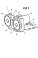
- FIGS. Fig. 2 is a perspective view showing the guide device 12
- Fig. 3 is a plan view
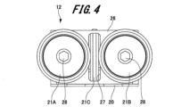
- Fig. 4 is a front view
- Fig. 5 is a side view
- Fig. 6 is a rear view.
- the guide device 12 has a base plate 20, a first guide roller 21A, a second guide roller 21B, and a third guide roller 21C.
- the guide device 12 also has a movable bracket 24, a fixed bracket 25, a support bracket 26, and a torsion spring 30, which is an example of a biasing member.
- the base plate 20 is formed in a generally flat plate shape.
- the base plate 20 is fixed to the car 2.
- a notch 23 is formed in the middle of one side of the base plate 20.
- the guide rail 3 (see FIG. 1) is inserted into the notch 23 of the base plate 20.
- a flat support bracket 26 is fixed to the base plate 20 near the side where the notch 23 is provided.
- the support bracket 26 stands approximately vertically from one surface of the base plate 20.
- the plane of the support bracket 26 is arranged approximately parallel to one side of the base plate 20 where the notch 23 is provided.
- the first guide roller 21A is rotatably supported via a rotating shaft 28 on one side in the width direction of the support bracket 26.
- the second guide roller 21B is rotatably supported via a rotating shaft 28 on the other side in the width direction of the support bracket 26.
- the first guide roller 21A and the second guide roller 21B are arranged symmetrically to each other on the support bracket 26.
- the first guide roller 21A and the second guide roller 21B sandwich both sides of the guide rail 3 (see FIG. 1).
- an opening 27 is formed in the middle of the support bracket 26 in the width direction, i.e., between the first guide roller 21A and the second guide roller 21B.
- the opening 27 is open along the up-down direction of the support bracket 26.
- a flat fixed bracket 25 is fixed to the base plate 20.
- the fixed bracket 25 is disposed on the rear side of the support bracket 26, opposite the front side where the first guide roller 21A and the second guide roller 21B are provided.
- the fixed bracket 25 stands upright approximately vertically from one surface of the base plate 20.
- the plane of the fixed bracket 25 is perpendicular to the plane of the support bracket 26.
- the fixed bracket 25 is provided with a rotating shaft 36.
- the axial direction of the rotating shaft 36 is perpendicular to the axial direction of the rotating shaft 28 provided on the support bracket 26.
- the movable bracket 24 is rotatably supported on the rotating shaft 36.
- the movable bracket 24 is formed in a flat plate shape.
- the movable bracket 24 is rotatably supported on the rotating shaft 36, and its plane is arranged parallel to the plane of the fixed bracket 25.
- a top rotating shaft 35 is provided on the movable bracket 24 above the rotating shaft 36 in the vertical direction.
- the axial direction of the top rotating shaft 35 is perpendicular to the axial direction of the rotating shaft 28 provided on the support bracket 26.
- the axial direction of the top rotating shaft 35 is parallel to the axial direction of the pivot shaft 36.
- the third guide roller 21C is rotatably supported on the top rotating shaft 35.
- the third guide roller 21C is rotatably supported on the movable bracket 24 via the top rotation shaft 35.
- the third guide roller 21C is disposed between the first guide roller 21A and the second guide roller 21B.
- a portion of the third guide roller 21C protrudes from the opening 27 of the support bracket 26, and faces and contacts the top surface of the guide rail 3 (see FIG. 1).
- a spring receiving portion 29 is formed on the other end of the movable bracket 24 opposite the end facing the support bracket 26.
- the spring receiving portion 29 is formed in a hook shape that is open downward in the vertical direction.
- a torsion spring 30, which is an example of a biasing member, is installed on the base plate 20.
- the torsion spring 30 is disposed on the other end of the movable bracket 24 opposite the one end facing the support bracket 26.
- the torsion spring 30 is disposed at a position farther away from the support bracket 26 than the fixed bracket 25 on which the pivot shaft 36 is provided.
- the torsion spring 30 is disposed between the spring receiving portion 29 of the movable bracket 24 and the base plate 20.
- the torsion spring 30 has its main body and one end 32 placed on one surface of the base plate 20.
- the spring extension 31 which is the end of the torsion spring 30 opposite the one end 32, protrudes obliquely in a direction away from the main body of the torsion spring 30 (upward in the vertical direction in this example).
- the spring extension 31 releasably engages with the spring receiving portion 29 of the movable bracket 24.
- the tip 31a of the spring extension 31 extends further from the main body of the torsion spring 30 from the point of engagement with the spring receiving portion 29.
- the biasing force of the torsion spring 30 is transmitted to the spring bearing portion 29 via the spring extension portion 31.
- the force transmitted to the spring bearing portion 29 causes the movable bracket 24 to rotate about the pivot axis 36 in a direction approaching the support bracket 26 and the guide rail 3 (see FIG. 1).
- the third guide roller 21C rotatably supported by the movable bracket 24 is pressed toward the guide rail 3.
- the distance from the pivot shaft 36 to the spring bearing portion 29, which is the contact point of the torsion spring 30, is set longer than the distance from the pivot shaft 36 to the top pivot shaft 35 in the movable bracket 24. This allows the third guide roller 21C to be pressed against the guide rail 3 with a greater force even if the biasing force of the torsion spring 30 is reduced.
- the biasing force of the torsion spring 30 is preset so that the third guide roller 21C is biased against the guide rail 3 with a predetermined force.
- FIGS. Fig. 7 is a side view showing the operation of removing the torsion spring 30.
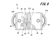
- Fig. 8 is a rear view showing the operation of removing the torsion spring 30.
- the worker When replacing the torsion spring 30, the worker first presses down the tip 31a of the spring extension 31 of the torsion spring 30 in a direction approaching the base plate 20. Then, as shown in Figures 7 and 8, the engagement between the spring extension 31 of the torsion spring 30 and the spring receiving portion 29 of the movable bracket 24 is released.
- the tip 31a is farther away from the body of the torsion spring 30 than the point of engagement with the spring receiving portion 29 of the torsion spring 30.
- the distance from the tip 31a to the body of the torsion spring 30 is set longer than the distance from the point of engagement with the spring receiving portion 29 of the spring extension portion 31 to the body. Therefore, due to the principle of leverage, the force that operates the tip 31a is smaller than the force with which the torsion spring 30 urges the movable bracket 24, i.e., the force with which it presses against the guide rail 3. This allows the torsion spring 30 to be easily removed from the base plate 20. As a result, the guide device 12 of this example makes it easy to install and replace the torsion spring 30, which is a urging member.
- the worker installs a new torsion spring 30 on the base plate 20. Then, by manipulating the tip 31a, the spring extension 31 of the torsion spring 30 engages with the spring receiving portion 29 of the movable bracket 24. This completes the replacement of the torsion spring 30.
- the spring force (biasing force) of the torsion spring 30 is pre-adjusted so that the third guide roller 21C is biased against the guide rail 3 with a predetermined force. This eliminates the need to adjust the biasing force in the guide device 12. As a result, the guide device 12 of this example makes it easy to install and replace the torsion spring 30, which is a biasing member.
- FIGS. Fig. 9 is a perspective view showing such a guide device according to the second embodiment
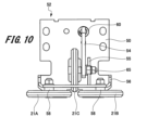
- Fig. 10 is a plan view
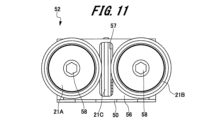
- Fig. 11 is a front view
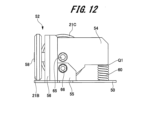
- Fig. 12 is a side view
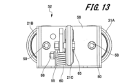
- Fig. 13 is a rear view.
- the guide device according to this second embodiment differs from the guide device 12 according to the first embodiment in the configuration of the biasing member. Therefore, parts common to the fuel assembly according to the first embodiment are given the same reference numerals and duplicated explanations are omitted.
- the guide device 52 has a base plate 50, a first guide roller 21A, a second guide roller 21B, and a third guide roller 21C.
- the guide device 52 also has a movable bracket 54, a fixed bracket 55, a support bracket 56, and a coil spring 60, which is an example of a biasing member.
- the first guide roller 21A and the second guide roller 21B are rotatably supported on the support bracket 56 via a rotating shaft 58.
- the third guide roller 21C is rotatably supported on the movable bracket 54 via a top rotating shaft 65, and a portion of it is exposed through an opening 57 in the support bracket 56.
- the movable bracket 54 is rotatably supported on the fixed bracket 55 via a rotating shaft 66.
- the coil spring 60 is disposed at the other end of the movable bracket 54 opposite the one end facing the support bracket 56.
- the coil spring 60 is disposed between the other end of the movable bracket 54 and the base plate 50.
- One end of the coil spring 60 is placed on one surface of the base plate 50, and the other end faces the other end of the movable bracket 54.
- the movable bracket 54 rotates in a direction such that the other end approaches the base plate 20.
- the coil spring 60 is compressed by the movable bracket 54, and a biasing force is generated as a reaction force.
- the biasing force generated in the coil spring 60 is transmitted to the movable bracket 54.
- the movable bracket 54 rotates about the rotation axis 66 in a direction approaching the support bracket 56 and the guide rail 3 (see FIG. 1), and the third guide roller 21C is pressed toward the guide rail 3.
- the spring force (biasing force) of the coil spring 60 is pre-adjusted so that when compressed, the third guide roller 21C is biased against the guide rail 3 with a predetermined force.
- the worker When replacing the coil spring 60 in the guide device 52 according to the second embodiment, the worker first moves the third guide roller 21C away from the guide rail 3. When the third guide roller 21C moves away from the guide rail 3, the compression of the coil spring 60 is released. Therefore, the biasing force with which the coil spring 60 biases the movable bracket 54 becomes smaller than when the third guide roller 21C is pressed against the guide rail 3. This allows the coil spring 60 to be easily removed from the base plate 50 without using tools or the like. As a result, the installation and replacement work of the coil spring 60, which is a biasing member, can be easily performed.
- the worker installs a new coil spring 60 on the base plate 50.
- the spring force (biasing force) of the coil spring 60 is pre-adjusted so that when compressed, it biases the third guide roller 21C against the guide rail 3 with a predetermined force. This eliminates the need to adjust the biasing force in the guide device 52.
- the guide device 52 of this example makes it easy to install and replace the coil spring 60, which is a biasing member.
- the rest of the configuration is the same as that of the guide device 12 according to the first embodiment, so a description of those components will be omitted.
- the guide device 52 according to the second embodiment which has such a configuration, can also provide the same effects as the guide device 12 according to the first embodiment described above.
- the third guide roller 21C is pressed against the guide rail 3, but the present invention is not limited to this.
- the first guide roller 21A and the second guide roller 21B are also attached to a movable bracket that is rotatably supported on a fixed bracket, similar to the third guide roller 21C. Then, the first guide roller 21A and the second guide roller 21B may be pressed against the guide rail 3 by a biasing member in a configuration similar to that described above.
- a spring extension may be provided as in the first embodiment, and the distance to the tip of the spring extension may be made longer than the distance from the main body to the contact point with the movable bracket. This allows the biasing force of the biasing member to be released by the principle of leverage, as in the first embodiment.
Landscapes
- Lift-Guide Devices, And Elevator Ropes And Cables (AREA)
Abstract
ガイド装置は、ベースプレートと、固定ブラケットと、可動ブラケットと、ガイドローラと、付勢部材と、を備えている。ベースプレートは、乗りかごに固定される。固定ブラケットは、ベースプレートに設置される。可動ブラケットは、固定ブラケットに回動軸を介して回動可能に支持される。ガイドローラは、可動ブラケットに回転軸を介して回転可能に支持される。付勢部材は、可動ブラケットとベースプレートの間に配置され、ガイドローラをガイドレールに向けて付勢する。そして、付勢部材をベースプレートから取り外す際、ガイドローラがガイドレールに押し当てたときの付勢力よりも小さい力で付勢部材の付勢力を解除可能に構成されている。
Description
本発明は、乗りかごをガイドするガイド装置及びエレベーターに関する。
一般的に、エレベーターの乗りかごには、ガイドレールに沿って乗りかごをガイドするガイド装置が設けられている。従来の、この種のガイド装置としては、例えば、特許文献1に記載されている技術がある。
特許文献1には、ベースプレートの上に配設された3個のローラガイドを備えた技術が記載されている。各ローラガイドは、略U字形をなす固定ブラケットと、固定ブラケットに揺動軸を介して支持された略U字形をなす可動ブラケットと、可動ブラケットにローラ軸を介して回転可能に支持された円盤状のガイドローラと、を備える。固定ブラケットの底壁と可動ブラケットの底壁との間に、コイルスプリングが圧縮状態で配設される。
しかしながら、特許文献1に記載された技術では、固定ブラケットの底壁から立ち上がったボルトと、可動ブラケットの底壁を貫通したボルトの先端部に螺合したナットとを用いてコイルスプリングを取り付けて4いる。そのため、付勢部材であるコイルスプリングを取り外す場合、コイルスプリングを締め付けるナットを緩めて、コイルスプリングの付勢力を解除する必要があった。さらに、復帰時には、所定の付勢力となるように、ナットを適切な締付トルクによる締め付ける必要があった。そのため、特許文献1に記載された技術では、付勢部材の取り付け作業や交換作業が大変煩雑なものとなっていた。
本目的は、上記の問題点を考慮し、付勢部材の取り付け作業や交換作業を容易に行うことができるガイド装置及びエレベーターを提供することにある。
上記課題を解決し、目的を達成するため、ガイド装置は、建築構造物に設けられた昇降路内を昇降移動する乗りかごに設けられ、ガイドレールに沿って乗りかごをガイドするガイド装置である。ガイド装置は、ベースプレートと、固定ブラケットと、可動ブラケットと、ガイドローラと、付勢部材と、を備えている。ベースプレートは、乗りかごに固定される。固定ブラケットは、ベースプレートに設置される。可動ブラケットは、固定ブラケットに回動軸を介して回動可能に支持される。ガイドローラは、可動ブラケットに回転軸を介して回転可能に支持される。付勢部材は、可動ブラケットとベースプレートの間に配置され、ガイドローラをガイドレールに向けて付勢する。そして、付勢部材をベースプレートから取り外す際、ガイドローラをガイドレールに押し当てたときの付勢力よりも小さい力で付勢部材の付勢力を解除可能に構成されている。
また、エレベーターは、建築構造物に設けられた昇降路内を昇降移動する乗りかごと、昇降路内において乗りかごが昇降移動する方向に沿って立設されたガイドレールと、乗りかごに設けられ、ガイドレールに沿って乗りかごをガイドするガイド装置と、を備えている。そして、ガイド装置としては、上述したガイド装置が用いられる。
上記構成のガイド装置及びエレベーターによれば、付勢部材の取り付け作業や交換作業を容易に行うことができる。
以下、実施の形態例にかかるガイド装置及びエレベーターについて、図1~図13を参照して説明する。なお、各図において共通の部材には、同一の符号を付している。
1.第1の実施の形態例
1-1.エレベーターの構成例
まず、第1の実施の形態例(以下、「本例」という。)にかかるエレベーターの構成について、図1を参照して説明する。
図1は、本例のエレベーターの構成例を示す概略構成図である。
1-1.エレベーターの構成例
まず、第1の実施の形態例(以下、「本例」という。)にかかるエレベーターの構成について、図1を参照して説明する。
図1は、本例のエレベーターの構成例を示す概略構成図である。
図1に示すように、エレベーター1は、建築構造物に設けられた昇降路100内を昇降する乗りかご2と、乗りかご2を移動可能に支持するガイドレール3と、乗りかご2に接続される不図示の主ロープ等を有している。ガイドレール3は、乗りかご2の昇降移動する上下方向と直交する幅方向の両側に配置されて、乗りかご2の昇降方向に沿って昇降路100内に立設されている。また、ガイドレール3は、断面T字形をなすように一体となった一般的なT字形ガイドレールである。
また、エレベーター1は、主ロープが巻き掛けられる不図示の巻上機を有している。そして、巻上機が駆動することで、主ロープと共に乗りかご2は、昇降路100内を昇降移動する。
乗りかご2は、人や荷物が出入りするためかご室10を有している。かご室10には、開口部が設けられており、この開口部には、ドア11が開閉可能に設置されている。また、乗りかご2には、ガイドレール3に沿って乗りかご2をガイドするガイド装置12が設けられている。ガイド装置12は、かご室10の上部と下部に配置されている。幅方向の両側に配置されている。そして、ガイド装置12は、ガイドレール3と対向する。
1-2.ガイド装置の構成
次に、ガイド装置12の構成について図2から図6を参照して説明する。
図2は、ガイド装置12を示す斜視図、図3は平面図である。図4は正面図、図5は側面図、図6は背面図である。
次に、ガイド装置12の構成について図2から図6を参照して説明する。
図2は、ガイド装置12を示す斜視図、図3は平面図である。図4は正面図、図5は側面図、図6は背面図である。
図2から図6に示すように、ガイド装置12は、ベースプレート20と、第1ガイドローラ21Aと、第2ガイドローラ21Bと、第3ガイドローラ21Cと、を有している。また、ガイド装置12は、可動ブラケット24と、固定ブラケット25と、支持ブラケット26と、付勢部材の一例を示すねじりバネ30とを有している。
ベースプレート20は、略平板状に形成されている。ベースプレート20は、乗りかご2に固定される。ベースプレート20の一辺の中間部には、切欠き23が形成されている。ベースプレート20の切欠き23には、ガイドレール3(図1参照)が挿通する。ベースプレート20における切欠き23が設けられた一辺の近傍には、平板状の支持ブラケット26が固定されている。
支持ブラケット26は、ベースプレート20の一面から略垂直に立設している。支持ブラケット26は、その平面がベースプレート20における切欠き23が設けられた一辺と略平行に配置されている。支持ブラケット26の幅方向の一側には、第1ガイドローラ21Aが回転軸28を介して回転可能に支持されている。また、支持ブラケット26の幅方向の他側には、第2ガイドローラ21Bが回転軸28を介して回転可能に支持されている。第1ガイドローラ21Aと第2ガイドローラ21Bは、支持ブラケット26に互いに対称となるように配置されている。そして、第1ガイドローラ21Aと第2ガイドローラ21Bによって、ガイドレール3(図1参照)の両側面が挟み込まれる。
さらに、支持ブラケット26の幅方向の中間部、すなわち第1ガイドローラ21Aと第2ガイドローラ21Bの間には、開口部27が形成されている。開口部27は、支持ブラケット26の上下方向に沿って開口している。開口部27には、後述する第3ガイドローラ21Cの一部が突出している。
また、ベースプレート20には、平板状の固定ブラケット25が固定されている。固定ブラケット25は、支持ブラケット26における第1ガイドローラ21A及び第2ガイドローラ21Bが設けられた正面とは反対側の背面側に配置されている。固定ブラケット25は、ベースプレート20の一面から略垂直に立設している。そして、固定ブラケット25は、その平面が支持ブラケット26の平面に対して直交している。
固定ブラケット25には、回動軸36が設けられている。回動軸36の軸方向は、支持ブラケット26に設けた回転軸28の軸方向と直交している。回動軸36には、可動ブラケット24が回動可能に支持されている。可動ブラケット24は、平板状に形成されている。可動ブラケット24は、回動軸36に回動可能に支持されて、その平面が固定ブラケット25の平面と平行に配置されている。また、可動ブラケット24における回動軸36よりも上下方向の上方には、頂部回転軸35が設けられている。
頂部回転軸35の軸方向は、支持ブラケット26に設けた回転軸28の軸方向と直交している。また、頂部回転軸35の軸方向は、回動軸36の軸方向と平行をなす。そして、頂部回転軸35には、第3ガイドローラ21Cが回転可能に支持されている。
第3ガイドローラ21Cは、頂部回転軸35を介して可動ブラケット24に回転可能に支持されている。第3ガイドローラ21Cは、第1ガイドローラ21Aと第2ガイドローラ21Bの間に配置される。そして、第3ガイドローラ21Cは、その一部が支持ブラケット26の開口部27から突出し、ガイドレール3(図1参照)の頂面と対向し、かつ接触する。
また、可動ブラケット24における支持ブラケット26と対向する一端部とは反対側の他端部には、バネ受け部29が形成されている。ばね受け部29は、上下方向の下方が開放したフック状に形成されている。バネ受け部29には、後述するねじりバネ30のバネ延長部31が係合する。
さらに、ベースプレート20には、付勢部材の一例を示すねじりバネ30が設置されている。ねじりバネ30は、可動ブラケット24における支持ブラケット26と対向する一端部とは反対側の他端部に配置されている。すなわち、ねじりバネ30は、回動軸36が設けられた固定ブラケット25よりも支持ブラケット26から離れた位置に配置されている。そして、ねじりバネ30は、可動ブラケット24のばね受け部29とベースプレート20との間に配置される。
ねじりバネ30は、その本体部及び一端部32がベースプレート20の一面に載置されている。図6に示すように、ねじりバネ30における一端部32とは反対側の端部であるバネ延長部31は、ねじりバネ30の本体部から離反する方向(本例では上下方向の上方)に向けて斜めに突出している。そして、バネ延長部31は、可動ブラケット24のバネ受け部29に解除可能に係合している。また、バネ延長部31の先端部31aは、バネ受け部29との係合箇所から更にねじりバネ30の本体部から延在している。
ねじりバネ30の付勢力は、バネ延長部31を介してバネ受け部29に伝達される。そして、可動ブラケット24は、バネ受け部29に伝達された力により、回動軸36を中心に支持ブラケット26及びガイドレール3(図1参照)に近づく方向に回動する。そのため、可動ブラケット24に回転可能に支持された第3ガイドローラ21Cは、ガイドレール3に向けて押圧される。
また、可動ブラケット24における回動軸36から頂部回転軸35までの距離よりも、回動軸36からねじりバネ30の接点であるばね受け部29までの距離のほうが長く設定されている。これにより、ねじりバネ30の付勢力を小さくしても、より大きな力で第3ガイドローラ21Cをガイドレール3に押し当てることができる。ここで、ねじりバネ30は、第3ガイドローラ21Cが所定の力でガイドレール3に付勢されるように、その付勢力が予め設定されている。
1-3.付勢部材の交換作業
次に、上述した構成を有するガイド装置12における付勢部材であるねじりバネ30の交換作業について図7及び図8を参照して説明する。
図7は、ねじりバネ30の取り外し動作を示す側面図。図8は、ねじりバネ30の取り外し動作を示す背面図である。
次に、上述した構成を有するガイド装置12における付勢部材であるねじりバネ30の交換作業について図7及び図8を参照して説明する。
図7は、ねじりバネ30の取り外し動作を示す側面図。図8は、ねじりバネ30の取り外し動作を示す背面図である。
ねじりバネ30の交換作業を行う際、作業者は、まず、ねじりバネ30のバネ延長部31の先端部31aをベースプレート20に接近する向きに押し下げる。そして、図7及び図8に示すように、ねじりバネ30のバネ延長部31と可動ブラケット24のバネ受け部29との係合を解除する。
ここで、先端部31aは、ねじりバネ30におけるバネ受け部29との係合箇所よりもねじりバネ30の本体部から距離が離れている。すなわち、先端部31aからねじりバネ30の本体部までの距離は、バネ延長部31におけるバネ受け部29との係合箇所から本体部までの距離よりも長く設定されている。そのため、てこの原理により、先端部31aを操作する力は、ねじりバネ30が可動ブラケット24を付勢する力、すなわちガイドレール3に対する押圧する力よりも小さくなる。これにより、ねじりバネ30を容易にベースプレート20から取り外しことができる。その結果、本例のガイド装置12によれば、付勢部材であるねじりバネ30の取り付け作業や交換作業を容易に行うことができる。
古いねじりバネ30の取り外し作業が終了すると、作業者は、新しいねじりバネ30をベースプレート20に設置する。そして、先端部31aを操作し、ねじりバネ30のバネ延長部31を可動ブラケット24のバネ受け部29に係合させる。これにより、ねじりバネ30の交換作業が完了する。
なお、ねじりバネ30のバネ力(付勢力)は、第3ガイドローラ21Cが所定の力でガイドレール3に付勢される力となるように予め調整されている。これにより、ガイド装置12における付勢力の調整作業が不要となる。その結果、本例のガイド装置12によれば、付勢部材であるねじりバネ30の取り付け作業や交換作業を容易に行うことができる。
2.第2の実施の形態例
次に、第2の実施の形態例にかかるガイド装置について図9から図13を参照して説明する。
図9は、第2の実施の形態例いかかるガイド装置を示す斜視図、図10は平面図である。図11は正面図、図12は側面図、図13は背面図である。
次に、第2の実施の形態例にかかるガイド装置について図9から図13を参照して説明する。
図9は、第2の実施の形態例いかかるガイド装置を示す斜視図、図10は平面図である。図11は正面図、図12は側面図、図13は背面図である。
この第2の実施の形態例にかかるガイド装置が、第1の実施の形態例にかかるガイド装置12と異なる点は、付勢部材の構成である。そのため、第1の実施の形態例にかかる燃料集合体と共通する部分には、同一の符号を付して重複した説明を省略する。
図9から図13に示すように、ガイド装置52は、ベースプレート50と、第1ガイドローラ21Aと、第2ガイドローラ21Bと、第3ガイドローラ21Cと、を有している。また、ガイド装置52は、可動ブラケット54と、固定ブラケット55と、支持ブラケット56と、付勢部材の一例を示すコイルバネ60とを有している。
第1ガイドローラ21Aと第2ガイドローラ21Bは、回転軸58を介して支持ブラケット56に回転可能に支持されている。第3ガイドローラ21Cは、頂部回転軸65を介して可動ブラケット54に回転可能に支持されており、その一部が支持ブラケット56の開口部57から露出している。また、可動ブラケット54は、回動軸66を介して固定ブラケット55に回動可能に支持されている。
コイルバネ60は、可動ブラケット54における支持ブラケット56と対向する一端部とは反対側の他端部に配置されている。コイルバネ60は、可動ブラケット54の他端部とベースプレート50との間に配置される。そして、コイルバネ60は、一端部がベースプレート50の一面に載置され、他端部が可動ブラケット54の他端部と対向している。
図12に示すように、第3ガイドローラ21Cがガイドレール3(図1参照)と接触する前の状態では、コイルバネ60と可動ブラケット54との間に若干の隙間Q1が形成されている。そのため、ガイド装置52を設置する前の状態では、コイルバネ60の付勢力は、第3ガイドローラ21C及び第3ガイドローラ21Cには伝達されない。なお、コイルバネ60と可動ブラケット54とを接触させてもよい。
そして、ガイド装置52を設置し、第3ガイドローラ21Cをガイドレール3に接触させると、可動ブラケット54は、その他端部がベースプレート20に接近する方向に回動する。そのため、コイルバネ60は、可動ブラケット54により圧縮されて、その反力として付勢力が発生する。コイルバネ60に発生した付勢力は、可動ブラケット54に伝達される。その結果、可動ブラケット54が回動軸66を中心に支持ブラケット56及びガイドレール3(図1参照)に近づく方向に回動し、第3ガイドローラ21Cは、ガイドレール3に向けて押圧される。ここで、コイルバネ60のバネ力(付勢力)は、圧縮した際に、第3ガイドローラ21Cが所定の力でガイドレール3に付勢される力となるように予め調整されている。
この第2の実施の形態例にかかるガイド装置52において、コイルバネ60を交換する際、まず作業者は、第3ガイドローラ21Cをガイドレール3から離反させる。第3ガイドローラ21Cがガイドレール3から離反すると、コイルバネ60の圧縮が解除される。そのため、コイルバネ60が可動ブラケット54を付勢する付勢力は、第3ガイドローラ21Cをガイドレール3に押し当てた状態よりも小さくなる。これにより、工具等を用いることなく、コイルバネ60を容易にベースプレート50から取り外すことができる。その結果、付勢部材であるコイルバネ60の取り付け作業や交換作業を容易に行うことができる。
古いコイルバネ60の取り外し作業が終了すると、作業者は、新しいコイルバネ60をベースプレート50に設置する。ここで、上述したように、コイルバネ60のバネ力(付勢力)は、圧縮した際に、第3ガイドローラ21Cが所定の力でガイドレール3に付勢される力となるように予め調整されている。これにより、ガイド装置52における付勢力の調整作業が不要となる。その結果、本例のガイド装置52によれば、付勢部材であるコイルバネ60の取り付け作業や交換作業を容易に行うことができる。
その他の構成は、第1の実施の形態例にかかるガイド装置12と同様であるため、それらの説明は省略する、このような構成を有する第2の実施の形態例にかかるガイド装置52においても、上述した第1の実施の形態例にかかるガイド装置12と同様の作用効果を得ることができる。
なお、上述しかつ図面に示した実施の形態に限定されるものではなく、請求の範囲に記載した発明の要旨を逸脱しない範囲内で種々の変形実施が可能である。
また、上述した実施の形態例では、第3ガイドローラ21Cをガイドレール3に押し当てる構成について説明したが、これに限定されるものではない。例えば、第1ガイドローラ21A及び第2ガイドローラ21Bにおいても、第3ガイドローラ21Cと同様に、固定ブラケットに回動可能に支持される可動ブラケットに取り付ける。そして、上述した構成と同様の構成で、付勢部材により第1ガイドローラ21A及び第2ガイドローラ21Bをガイドレール3に押し当ててもよい。
また、付勢部材としてコイルバネを適用した場合でも、第1の実施の形態例と同様に、バネ延長部を設け、本体部から可動ブラケットとの接点までの距離よりも、バネ延長部の先端部までの距離を長くしてもよい。これにより、第1の実施の形態例と同様に、てこの原理により付勢部材の付勢力を解除することができる。
なお、本明細書において、「平行」及び「直交」等の単語を使用したが、これらは厳密な「平行」及び「直交」のみを意味するものではなく、「平行」及び「直交」を含み、さらにその機能を発揮し得る範囲にある、「略平行」や「略直交」の状態であってもよい。
1…エレベーター、 2…乗りかご、 3…ガイドレール、 10…かご室、 12、52…ガイド装置、 20、50…ベースプレート、 21A…第1ガイドローラ、 21B…第2ガイドローラ、 21C…第3ガイドローラ、 24、54…可動ブラケット、 25、55…固定ブラケット、 26、56…支持ブラケット、 28、58…回転軸、 29…バネ受け部、 30…ねじりバネ(付勢部材)、 31…バネ延長部、 31a…先端部、 32…一端部、 35、65…頂部回転軸、 36、66…回動軸、 100…昇降路、 Q1…隙間
Claims (7)
- 建築構造物に設けられた昇降路内を昇降移動する乗りかごに設けられ、ガイドレールに沿って乗りかごをガイドするガイド装置において、
前記乗りかごに固定されるベースプレートと、
前記ベースプレートに設置された固定ブラケットと、
前記固定ブラケットに回動軸を介して回動可能に支持される可動ブラケットと、
前記可動ブラケットに回転軸を介して回転可能に支持されるガイドローラと、
前記可動ブラケットと前記ベースプレートの間に配置され、前記ガイドローラを前記ガイドレールに向けて付勢する付勢部材と、を備え、
前記付勢部材をベースプレートから取り外す際、前記ガイドローラを前記ガイドレールに押し当てたときの付勢力よりも小さい力で前記付勢部材の付勢力を解除可能に構成されている
ガイド装置。 - 前記可動ブラケットにおける前記回動軸から前記回転軸までの距離よりも、前記回動軸から前記可動ブラケットにおける前記付勢部材との接点までの距離のほうが長く設定されている
請求項1に記載のガイド装置。 - 前記付勢部材は、ねじりバネである
請求項1に記載のガイド装置。 - 前記付勢部材は、本体部及び一端部が前記ベースプレートに設置され、前記一端部とは反対側の端部であるバネ延長部が前記本体部から離反する方向に突出し、
前記バネ延長部は、前記可動ブラケットに設けたバネ受け部に解除可能に係合される
請求項3に記載のガイド装置。 - 前記バネ延長部の先端部から前記本体部までの距離は、前記バネ延長部における前記バネ受け部との係合箇所から前記本体部までの距離よりも長く設定されている
請求項4に記載のガイド装置。 - 前記付勢部材の付勢力は、前記ガイドローラが所定の力で前記ガイドレールに付勢される力となるように予め調整されている
請求項1に記載のガイド装置。 - 建築構造物に設けられた昇降路内を昇降移動する乗りかごと、
前記昇降路内において前記乗りかごが昇降移動する方向に沿って立設されたガイドレールと、
前記乗りかごに設けられ、前記ガイドレールに沿って前記乗りかごをガイドするガイド装置と、を備え、
前記ガイド装置は、
前記乗りかごに固定されるベースプレートと、
前記ベースプレートに設置された固定ブラケットと、
前記固定ブラケットに回動軸を介して回動可能に支持される可動ブラケットと、
前記可動ブラケットに回転軸を介して回転可能に支持されるガイドローラと、
前記可動ブラケットと前記ベースプレートの間に配置され、前記ガイドローラを前記ガイドレールに向けて付勢する付勢部材と、を備え、
前記付勢部材をベースプレートから取り外す際、前記ガイドローラを前記ガイドレールに押し当てたときの付勢力よりも小さい力で前記付勢部材の付勢力を解除可能に構成されている
エレベーター。
Priority Applications (1)
| Application Number | Priority Date | Filing Date | Title |
|---|---|---|---|
| PCT/JP2023/000267 WO2024150263A1 (ja) | 2023-01-10 | 2023-01-10 | ガイド装置及びエレベーター |
Applications Claiming Priority (1)
| Application Number | Priority Date | Filing Date | Title |
|---|---|---|---|
| PCT/JP2023/000267 WO2024150263A1 (ja) | 2023-01-10 | 2023-01-10 | ガイド装置及びエレベーター |
Publications (1)
| Publication Number | Publication Date |
|---|---|
| WO2024150263A1 true WO2024150263A1 (ja) | 2024-07-18 |
Family
ID=91896570
Family Applications (1)
| Application Number | Title | Priority Date | Filing Date |
|---|---|---|---|
| PCT/JP2023/000267 Ceased WO2024150263A1 (ja) | 2023-01-10 | 2023-01-10 | ガイド装置及びエレベーター |
Country Status (1)
| Country | Link |
|---|---|
| WO (1) | WO2024150263A1 (ja) |
Citations (4)
| Publication number | Priority date | Publication date | Assignee | Title |
|---|---|---|---|---|
| WO2012066587A1 (ja) * | 2010-11-15 | 2012-05-24 | 株式会社 日立製作所 | 乗りかごドア気密装置及びエレベータ装置 |
| JP2017218253A (ja) * | 2016-06-06 | 2017-12-14 | 日本オーチス・エレベータ株式会社 | エレベータのローラガイド装置 |
| US20200002129A1 (en) * | 2018-06-27 | 2020-01-02 | Thyssenkrupp Elevator Ag | Counterweight slack belt detection switch |
| US20200317472A1 (en) * | 2019-04-03 | 2020-10-08 | Elevator Safety Company | Elevator guide |
-
2023
- 2023-01-10 WO PCT/JP2023/000267 patent/WO2024150263A1/ja not_active Ceased
Patent Citations (4)
| Publication number | Priority date | Publication date | Assignee | Title |
|---|---|---|---|---|
| WO2012066587A1 (ja) * | 2010-11-15 | 2012-05-24 | 株式会社 日立製作所 | 乗りかごドア気密装置及びエレベータ装置 |
| JP2017218253A (ja) * | 2016-06-06 | 2017-12-14 | 日本オーチス・エレベータ株式会社 | エレベータのローラガイド装置 |
| US20200002129A1 (en) * | 2018-06-27 | 2020-01-02 | Thyssenkrupp Elevator Ag | Counterweight slack belt detection switch |
| US20200317472A1 (en) * | 2019-04-03 | 2020-10-08 | Elevator Safety Company | Elevator guide |
Similar Documents
| Publication | Publication Date | Title |
|---|---|---|
| JP2790615B2 (ja) | エレベータ用調速機 | |
| CN101605713B (zh) | 电梯的安全装置 | |
| CN101808926B (zh) | 电梯的安全装置 | |
| US6021872A (en) | Remote brake release mechanism for an elevator machine | |
| CN100593505C (zh) | 电梯的轿厢门联锁装置 | |
| KR101267004B1 (ko) | 수동제동장치가 부착된 비상정지장치 | |
| JP4369156B2 (ja) | エレベータかご用の安全制動装置を係合するための機器 | |
| WO2024150263A1 (ja) | ガイド装置及びエレベーター | |
| US20180208433A1 (en) | Safety block for elevator | |
| JP7004220B2 (ja) | エレベータ用ガイドレール保持装置 | |
| CN102858671B (zh) | 电梯的紧急停止装置 | |
| JP6522564B2 (ja) | 調速機、および、試験装置 | |
| JP6567712B2 (ja) | エレベータの乗場ドア解錠装置 | |
| JP6598891B2 (ja) | エレベータ | |
| KR102341995B1 (ko) | 승강기용 시브제동장치 | |
| JP3889948B2 (ja) | エレベータ調速機のロープ掴み機構 | |
| US20250353703A1 (en) | Elevator | |
| EP4527776A1 (en) | Elevator | |
| JP2009091098A (ja) | エレベータ用ホールドア | |
| CN115108431B (zh) | 提拉机构、提拉装置以及电梯 | |
| JP6697663B1 (ja) | エレベータのドアパネル位置決め装置 | |
| KR102341994B1 (ko) | 승강기용 시브제동장치 | |
| JP4546847B2 (ja) | エレベータの調速機ロープ浮かせツールおよび治具 | |
| CN110217666B (zh) | 钢丝绳制动装置 | |
| CN120322401A (zh) | 电梯以及紧急制动装置的复位方法 |
Legal Events
| Date | Code | Title | Description |
|---|---|---|---|
| 121 | Ep: the epo has been informed by wipo that ep was designated in this application |
Ref document number: 23915887 Country of ref document: EP Kind code of ref document: A1 |
|
| NENP | Non-entry into the national phase |
Ref country code: DE |
|
| 122 | Ep: pct application non-entry in european phase |
Ref document number: 23915887 Country of ref document: EP Kind code of ref document: A1 |