WO2024147329A1 - 測定装置及び測定システム - Google Patents
測定装置及び測定システム Download PDFInfo
- Publication number
- WO2024147329A1 WO2024147329A1 PCT/JP2023/047094 JP2023047094W WO2024147329A1 WO 2024147329 A1 WO2024147329 A1 WO 2024147329A1 JP 2023047094 W JP2023047094 W JP 2023047094W WO 2024147329 A1 WO2024147329 A1 WO 2024147329A1
- Authority
- WO
- WIPO (PCT)
- Prior art keywords
- sensors
- deformation layer
- layer
- measurement
- measuring device
- Prior art date
- Legal status (The legal status is an assumption and is not a legal conclusion. Google has not performed a legal analysis and makes no representation as to the accuracy of the status listed.)
- Ceased
Links
Images











Classifications
-
- G—PHYSICS
- G01—MEASURING; TESTING
- G01B—MEASURING LENGTH, THICKNESS OR SIMILAR LINEAR DIMENSIONS; MEASURING ANGLES; MEASURING AREAS; MEASURING IRREGULARITIES OF SURFACES OR CONTOURS
- G01B7/00—Measuring arrangements characterised by the use of electric or magnetic techniques
- G01B7/16—Measuring arrangements characterised by the use of electric or magnetic techniques for measuring the deformation in a solid, e.g. by resistance strain gauge
-
- G—PHYSICS
- G01—MEASURING; TESTING
- G01B—MEASURING LENGTH, THICKNESS OR SIMILAR LINEAR DIMENSIONS; MEASURING ANGLES; MEASURING AREAS; MEASURING IRREGULARITIES OF SURFACES OR CONTOURS
- G01B11/00—Measuring arrangements characterised by the use of optical techniques
- G01B11/24—Measuring arrangements characterised by the use of optical techniques for measuring contours or curvatures
-
- G—PHYSICS
- G01—MEASURING; TESTING
- G01L—MEASURING FORCE, STRESS, TORQUE, WORK, MECHANICAL POWER, MECHANICAL EFFICIENCY, OR FLUID PRESSURE
- G01L1/00—Measuring force or stress, in general
- G01L1/14—Measuring force or stress, in general by measuring variations in capacitance or inductance of electrical elements, e.g. by measuring variations of frequency of electrical oscillators
-
- G—PHYSICS
- G01—MEASURING; TESTING
- G01L—MEASURING FORCE, STRESS, TORQUE, WORK, MECHANICAL POWER, MECHANICAL EFFICIENCY, OR FLUID PRESSURE
- G01L1/00—Measuring force or stress, in general
- G01L1/14—Measuring force or stress, in general by measuring variations in capacitance or inductance of electrical elements, e.g. by measuring variations of frequency of electrical oscillators
- G01L1/142—Measuring force or stress, in general by measuring variations in capacitance or inductance of electrical elements, e.g. by measuring variations of frequency of electrical oscillators using capacitors
- G01L1/146—Measuring force or stress, in general by measuring variations in capacitance or inductance of electrical elements, e.g. by measuring variations of frequency of electrical oscillators using capacitors for measuring force distributions, e.g. using force arrays
-
- G—PHYSICS
- G01—MEASURING; TESTING
- G01L—MEASURING FORCE, STRESS, TORQUE, WORK, MECHANICAL POWER, MECHANICAL EFFICIENCY, OR FLUID PRESSURE
- G01L1/00—Measuring force or stress, in general
- G01L1/20—Measuring force or stress, in general by measuring variations in ohmic resistance of solid materials or of electrically-conductive fluids; by making use of electrokinetic cells, i.e. liquid-containing cells wherein an electrical potential is produced or varied upon the application of stress
-
- G—PHYSICS
- G01—MEASURING; TESTING
- G01L—MEASURING FORCE, STRESS, TORQUE, WORK, MECHANICAL POWER, MECHANICAL EFFICIENCY, OR FLUID PRESSURE
- G01L1/00—Measuring force or stress, in general
- G01L1/20—Measuring force or stress, in general by measuring variations in ohmic resistance of solid materials or of electrically-conductive fluids; by making use of electrokinetic cells, i.e. liquid-containing cells wherein an electrical potential is produced or varied upon the application of stress
- G01L1/205—Measuring force or stress, in general by measuring variations in ohmic resistance of solid materials or of electrically-conductive fluids; by making use of electrokinetic cells, i.e. liquid-containing cells wherein an electrical potential is produced or varied upon the application of stress using distributed sensing elements
-
- G—PHYSICS
- G01—MEASURING; TESTING
- G01L—MEASURING FORCE, STRESS, TORQUE, WORK, MECHANICAL POWER, MECHANICAL EFFICIENCY, OR FLUID PRESSURE
- G01L5/00—Apparatus for, or methods of, measuring force, work, mechanical power, or torque, specially adapted for specific purposes
Definitions
- the measurement system of the fifteenth invention is a measurement system in which, compared to the thirteenth or fourteenth invention, the multiple sensors are arranged in a matrix of N rows and M columns, the processing unit is configured to obtain a measurement result using a detection result that is a combination of the detection result of a first set of sensors to be read at a first reading opportunity and the detection result of a second set of sensors to be read at a second reading opportunity, the first set of sensors being sensors in even rows and even columns of the multiple sensors, and the second set of sensors being sensors in odd rows and odd columns of the multiple sensors.
- the measurement device and measurement system of the present invention can obtain measurement results of detection items related to an object so that the effects of the object's rigidity and shape are relatively small.
- the arrangement surface on which the multiple sensors 51 are arranged does not have to be flat.
- the sensor array unit 5 does not have to be sheet-shaped, and may have a curved arrangement surface, a circular arrangement surface, or a cylindrical arrangement surface.
- Each sensor 51 is, for example, a resistance change type pressure sensor, which is a well-known sensor. However, without being limited to this, each sensor 51 may also be a capacitance change type pressure sensor. By configuring the sensor array unit 5 using such sensors, it becomes possible to detect the pressure distribution of an object.
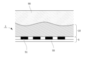
- the deformation layer 10 is disposed on top of the sensor array section 5.
- the deformation layer 10 is disposed so as to be located between the sensor array section 5 and the object to be detected. It can also be said that the deformation layer 10 is disposed so as to face the placement surface.
- the first layer 11 may have a filling portion 118 (shown in FIG. 9) instead of the isolating portion 113.
- the filling portion 118 is a portion filled between adjacent divided portions 111, and is made of a material different from the divided portions 111.
- a filling material different from the constituent material of the divided portions 111 may be disposed between each of the divided portions 111 in the first layer 11.
- the deformation layer 10 may be configured without the second layer 12, and even in this case, the deformation layer 10 can be configured as an integral part and easily disposed in the sensor array portion 5. An example of the configuration of the filling portion 118 made of such a filling material will be described later.
- FIG. 3 is a diagram illustrating detection of an object 90 using the measurement device 1.
- FIG. 4 is a diagram illustrating detection using a measurement device according to a comparative example.
- the state of the object 90 in order to measure the pressure distribution in the comparative example, strictly speaking, the state of the object 90, such as its softness, must all be known, making it difficult to perform accurate measurements.
- the measuring device 1 according to the present embodiment by measuring the changes in the physical properties of the flexible deformation layer 10, it is possible to obtain measurement results that can be considered as pressure distributions that reflect the hardness and shape of the object 90. Therefore, even for an object 90 that has unevenness or low rigidity, it is relatively easy and appropriate to measure the required detection items.
- the deformation layer 10 can be constructed using the following materials:
- the deformation layer 10 is constructed using a material with a Poisson's ratio of less than 0.2. With this configuration, the multiple divided parts 111 of the deformation layer 10 are less likely to interfere with each other when compressed, making it possible to obtain measurement results with high resolution in the direction along the placement surface.
- the deformation layer 10 is made of a material whose ratio of loss modulus to storage modulus (Tan ⁇ ) is 1/10 or less.
- a foam material with low viscosity such as urethane or silicone can be used.
- the deformation layer 10 can be made to quickly return to a steady state (a state in which transient deformation has subsided) after measurement. Therefore, measurements can be performed quickly, and measurements can be repeated again in a short time after the measurement is completed.
- Such materials may include, for example, synthetic resin sponges and rubber.
- the deformation layer 10 may be made of a foam material having a closed cell structure. By using such materials, the deformation layer 10 can be configured to have an appropriate viscosity.
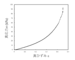
- Figure 5 shows the SS characteristics when a uniaxial compression test was performed on Wake Sangyo Co., Ltd.'s "EPT-03S.”
- the graph shows the relationship between true strain and true stress when a test piece 20 mm wide, 20 mm high, and 5 mm long is compressed at a speed of 0.5 mm per second.
- FIG. 6 is a diagram illustrating the deformation layer 10b in one modified example of the measuring device 1 according to this embodiment.
- the measuring device 1 shown in FIG. 6 is provided with a deformation layer 10b.
- the first layer 11, i.e., the layer in which the divided portions 111 are arranged is disposed above the second layer 12, i.e., the continuous portion 112.
- the proportion of the vertical dimension LC of the second layer 12 in the vertical dimension LA is less than 0.3.
- the measuring device 1 shown in FIG. 7 is provided with a deformation layer 10c.
- the second layer 12, i.e., the continuous portion 112 is located in the middle of the first layer 11, i.e., the layer in which the divided portions 111 are arranged.
- the proportion of the vertical dimension LC of the second layer 12 in the vertical dimension LA is less than 0.3.
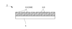
- the measuring device 1 shown in FIG. 8 is provided with a deformation layer 10d.
- a deformation layer 10d In the deformation layer 10d, only a layer (first layer) in which the divided parts 111 are arranged with isolating parts 113 interposed therebetween is provided, and no part corresponding to the second layer 12 in the above-mentioned embodiment is provided. Even with this structure, as described above, it is possible to obtain measurement results of detection items related to the object by making the effect of the rigidity and shape of the object on the measurement results relatively small.
- the measuring device 1 shown in FIG. 9 is provided with a deformation layer 10e.
- the deformation layer 10e there is no portion corresponding to the second layer 12 in the above-mentioned embodiment, and only a layer in which the divided portions 111 are arranged side by side with the filling portion 118 interposed therebetween is provided. Even with such a structure, as described above, it is possible to obtain measurement results of detection items related to the object by making the effect of the rigidity and shape of the object on the measurement results relatively small.
- the stiffness of the filling material that constitutes the filling portion 118 is half or less the stiffness of the material that constitutes the divided portion 111. More specifically, it is preferable that the stiffness of the filling material is about one-third the stiffness of the divided portion 111. This makes it possible to prevent the deformation of each divided portion 111 from affecting adjacent divided portions 111. Therefore, it is possible to obtain measurement results with high resolution in the horizontal direction.
- the effect of the rigidity and shape of the object on the measurement results is relatively small, and measurement results of the detection items related to the object can be obtained.
- the measuring device 1 can be suitably used to measure the pressure distribution on the contact surface (sometimes referred to as the measurement result of the sole of the foot) when, for example, a subject stands or walks with the sole of the foot in contact with the ground. That is, the shape of the sole of the human foot differs from person to person, and there are irregularities and differences in the hardness of the skin, etc. In some cases, the arch of the foot is located high (a so-called high arch) or there is a so-called floating toe. In such applications, by using the measuring device 1, the pressure distribution on the contact surface can be obtained corresponding to each of the soles of the feet having various shapes and characteristics. Therefore, it is possible to obtain measurement results that can be used for the purpose of making a judgment regarding the condition of the subject based on the measurement results of the pressure distribution on the contact surface.
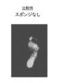
- FIG. 10 is a diagram showing an example of the measurement results of the sole of the foot in the comparative example.
- FIG. 11 is a diagram showing an example of the measurement results of the sole of the foot in the first configuration example.
- FIG. 12 is a diagram showing an example of the measurement results of the sole of the foot in the second configuration example.
- FIG. 13 is a diagram showing an example of the measurement results of the sole of the foot in the third configuration example.
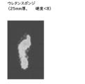
- FIG. 14 is a diagram showing an example of the measurement results of the sole of the foot in the fourth configuration example.
- the measurement results of the pressure distribution are shown as heat maps.
- the comparative examples are the measurement results when a measurement device without a deformation layer 10 is used.
- the deformation layer 10 is constructed using "EPT-03S” manufactured by Waki Sangyo Co., Ltd., which has a thickness LA of 5 mm and a hardness of 8 ⁇ 5.
- the deformation layer 10 is constructed using "EPT-03S” manufactured by Waki Sangyo Co., Ltd., which has a thickness LA of 10 mm and a hardness of 8 ⁇ 5.
- the deformation layer 10 is constructed using a material with a thickness LA of 20 mm and a hardness of 25 ⁇ 5.
- the deformation layer 10 is made of urethane sponge, which has a thickness LA of 25 mm and a hardness of less than 8.
- the pressure distribution in the arch area and the area of the second toe and beyond is not very clear in the measurement results. Therefore, it may be difficult to use the measurement results to determine whether or not the person has a high arch or floating toes.
- the measurement device 1 with the deformation layer 10 can capture the pressure distribution over a wider area of the sole of the foot than the comparative example.
- the thickness is too large, there may be a problem that the resolution of the pressure distribution in the horizontal direction becomes relatively low.
- the measurement device 1 can be configured to accommodate soles of various shapes while maintaining a relatively high resolution in the horizontal direction.
- the deformation layer 10 may be configured as in the other configuration examples so that appropriate measurement results can be obtained depending on the magnitude of stress that may occur during measurement (such as the weight of the subject) and other purposes.
- An example of a simulation result illustrating an example configuration of the measurement device 1 according to this embodiment is as follows:
- FIG. 15 is a diagram showing the simulation results of the measurement results of the sole of the foot in the fifth configuration example.
- FIG. 16 is a diagram showing the simulation results of the measurement results of the sole of the foot in the sixth configuration example.
- FIG. 17 is a diagram showing the simulation results of the measurement results of the sole of the foot in the seventh configuration example.
- the material of the deformation layer 10 was set to correlate well with the test results of the uniaxial compression test and the like as described above, and the Poisson's ratio was set to 0.
- a model of the foot with an appropriate Young's modulus was created, and the pressure distribution when a load was applied to the measuring device 1 was determined.
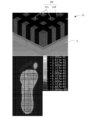
- Each figure shows a model of each configuration example of the measuring device 1, a heat map image showing the measurement results of the sole of the foot, and a legend for the measurement results.
- the fifth configuration example is an example using a deformation layer 10a with a thickness LA of 20 millimeters and a structure that is not divided into divided portions 111. In this case, the pressure distribution from the second finger to the fifth finger does not appear. This result can be used as a comparative example.
- the sixth configuration example is an example using a deformation layer 10d with a thickness LA of 20 mm and a structure in which divided sections 111 of 3.9 mm square are arranged side by side. In this case, the pressure distribution appears up to each finger, and it is clear that appropriate measurement results can be obtained.
- the seventh configuration example is an example using a deformation layer 10e with a thickness LA of 20 millimeters, in which divided sections 111 of 4 millimeters square are arranged with filling sections 118 in between.
- the rigidity of the filling sections 118 is set to one third of the rigidity of the divided sections 111. Even in this case, the pressure distribution appears up to each finger, and it is clear that appropriate measurement results can be obtained.
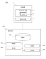
- FIG. 18 is a block diagram showing an example of a measurement system 900 according to this embodiment.
- the measurement device 1 includes a sensor array section 5 that is composed of multiple sensors 51, and a signal output section 3.
- the signal output unit 3 is configured to be able to transmit the detection results of the sensor array unit 5 detected by the multiple sensors 51 to the terminal device 600.
- the signal output unit 3 is configured, for example, by a circuit mounted on the substrate 55 of the sensor array unit 5, but is not limited to this.
- the signal output unit 3 is configured to be able to transmit, for example, data (which may be a signal) indicating the detection results of each of the multiple sensors 51 collectively for each reading opportunity (which may be called a frame) that arrives at a predetermined interval.
- data which may be a signal
- the data of the detection results of each of the multiple sensors 51 at a certain reading opportunity may be collectively referred to as one frame of data.
- the signal output unit 3 is configured to be able to transmit one frame of data including the detection results of the target sensor 51 being read at a predetermined frame rate (which may be called a sampling rate, etc.).
- the terminal device 600 includes, for example, a memory unit 610, a receiving unit 620, a reception unit 630, a processing unit 640, and an output unit 660.
- the receiving unit 620 receives information transmitted from the measuring device 1 or other devices via the network.
- the receiving unit 620 stores the received information, for example, in the storage unit 610, so that the processing unit 640 and the like can acquire the information.
- the receiving unit 620 is realized, for example, by a wireless or wired communication means.
- the processing unit 640 performs various information processing operations using each unit of the terminal device 600.
- the processing unit 640 is configured to read the detection results of the measuring device 1, for example, as described below, and obtain the measurement results based on the results.
- the processing unit 640 can usually be realized by an MPU, memory, etc.
- the processing procedure of the processing unit 640 is usually realized by software, and the software is recorded in a recording medium such as a ROM. However, it may also be realized by hardware (dedicated circuitry).
- the output unit 660 outputs information, for example, by displaying it on a display device. Note that the method of outputting information is not limited to this, and information may be output by outputting sound or the like from a speaker or the like.
- the output unit 660 is configured to be able to output information relating to the measurement results acquired by the processing unit 640, for example.
- the terminal device 600 receives the data output by the signal output unit 3 from the measuring device 1 through the receiving unit 620.
- the processing unit 640 is configured to read the received data and obtain the measurement results.
- the measurement system 900 is configured to perform sensor alternating reading of the measurement device 1 having multiple sensors 51. That is, the processing unit 640 obtains (reads) the detection results at one reading opportunity by using some of the multiple sensors as the reading target. The processing unit 640 obtains the detection results at multiple reading opportunities by setting a different sensor as the reading target for each reading opportunity. The processing unit 640 obtains the measurement results using the detection results obtained at each of the multiple reading opportunities in this manner. In other words, the processing unit 640 is configured to be able to obtain the measurement results using the results of sensor alternating reading of the measurement device 1 having multiple sensors 51.
- the sensor alternate reading is realized by, for example, the signal output unit 3 and the processing unit 640.
- two combinations of target sensors 51R to be read are set in advance (sometimes called a first set and a second set), and each time a reading opportunity arrives, the signal output unit 3 switches between transmitting data of the first set of target sensors 51R as one frame of data and transmitting data of the second set of target sensors 51R as one frame of data.
- the processing unit 640 obtains a measurement result using the first set of data and the second set of data transmitted at each reading opportunity.
- the processing unit 640 combines the first set of data and the second set of data transmitted at two consecutive reading opportunities, and obtains the measurement result as a set of data. This makes it possible to obtain a measurement result using data detected by all of the multiple sensors 51.
- the measurement result may be, but is not limited to, an image such as a still image or a moving image (time-series image) showing the pressure distribution.
- a deformation layer 10 is used in which the parts corresponding to each sensor 51 are not completely separated, and it is believed that the distortion of a part corresponding to one sensor 51 is affected by the distortion of the parts corresponding to other nearby sensors 51.
- the detection result of one sensor 51 may be related to the detection results of other nearby sensors 51.
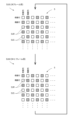
- FIG. 19 is a diagram explaining a specific example of a sensor reading method of the measurement system 900.
- a sensor array unit 5 in which sensors 51 are arranged in a matrix of N rows and M columns is used.
- the sensor alternating reading of this specific example for example, two combinations of target sensors 51 to be read are set.
- the sensor 51 in the even row and even column is the target sensor 51R
- the sensor 51 in the odd row and odd column is the non-target sensor 51S that is not to be read.
- the sensor 51 in the even row and even column is the non-target sensor 51S
- the sensor 51 in the odd row and odd column is the target sensor 51R.
- the detection results of the target sensors 51R in which adjacent sensors 51 in both the horizontal direction (row direction) and vertical direction (column direction) are non-target sensors 51S are acquired in each frame. Therefore, in each frame, the detection results of the multiple target sensors 51R are not highly correlated with each other.
- the first and second sets of data transmitted in succession are synthesized, and the processing unit 640 acquires the measurement results using this as a single set of data for a reading opportunity, thereby obtaining measurement results with a higher resolution.
- the target sensor 51R When performing sensor alternating reading, it is preferable to select the target sensor 51R for each frame so that, for example, neither of two adjacent sensors 51 in at least one direction is the target for reading in the same frame. This makes it possible to obtain more reliable and highly accurate results.
- the number of combinations of target sensors 51R to be read may be three or more. Also, the combinations of target sensors 51R may be determined randomly in each frame.
- the configuration of the measurement system 900 is not limited to the above, and some or all of the processing for realizing sensor alternating reading may be performed by the signal output unit 3 of the measurement device 1, etc.
- the measurement device 1 may be configured so that the above-mentioned processing unit 640 can be considered to be provided in the measurement device 1.
- sensor alternating reading may be realized by switching, for each frame, the reading results to be processed by the processing unit 640 from among the reading results of each of the multiple sensors 51 transmitted every frame from the signal output unit 3.
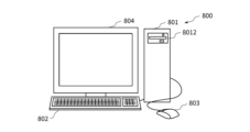
- FIG. 20 is an overview of the computer system 800 in the above embodiment.
- FIG. 21 is a block diagram of the computer system 800.
- Computer system 800 includes a computer 801, a keyboard 802, a mouse 803, and a monitor 804.
- the computer 801 includes an MPU 8013, a bus 8014 connected to the optical disk drive 8012 etc., a ROM 8015 for storing programs such as a boot-up program, a RAM 8016 connected to the MPU 8013 for temporarily storing instructions for application programs and providing temporary storage space, and a hard disk 8017 for storing application programs, system programs, and data.
- the computer 801 may further include a network card that provides a connection to a LAN.
- a program that causes computer system 800 to execute the functions of the terminal device or the like of the above-mentioned embodiments may be stored on optical disk 8101, inserted into optical disk drive 8012, and then transferred to hard disk 8017.
- the program may be sent to computer 801 via a network (not shown) and stored on hard disk 8017.
- the program is loaded into RAM 8016 when executed.
- the program may be loaded directly from optical disk 8101 or the network.
- the program does not necessarily have to include an operating system (OS) or a third party program that causes computer 801 to execute the functions of the terminal device of the above-mentioned embodiment.
- the program only needs to include an instruction portion that calls appropriate functions (modules) in a controlled manner to obtain the desired results. How computer system 800 operates is well known, and a detailed description will be omitted.
- the transmission step of transmitting information and the reception step of receiving information do not include processing performed by hardware, such as processing performed by a modem or interface card in the transmission step (processing that can only be performed by hardware).
- the computer that executes the above program may be a single computer or multiple computers. In other words, it may perform centralized processing or distributed processing.
- each component may be configured with dedicated hardware, or, for components that can be realized by software, may be realized by executing a program.
- each component may be realized by a program execution unit such as a CPU reading and executing a software program recorded on a recording medium such as a hard disk or semiconductor memory.
- the program execution unit may execute the program while accessing the storage unit or recording medium.
- the program may also be executed by being downloaded from a server or the like, or may be executed by reading a program recorded on a specified recording medium (e.g., an optical disk, a magnetic disk, a semiconductor memory, etc.).
- This program may also be used as a program that constitutes a program product.
- the program may also be executed by a single computer or multiple computers. In other words, centralized processing or distributed processing may be performed.
- each process may be realized by centralized processing in a single device (system), or may be realized by distributed processing by multiple devices (in this case, the entire system made up of multiple devices performing distributed processing can be considered as a single “device”).
- An embodiment may be constructed by appropriately combining the components of the above-mentioned embodiments and variations.
- it is not limited to the configuration of the above-mentioned embodiments, and each component of the above-mentioned embodiments and variations may be replaced or combined with components of other embodiments, etc., as appropriate.
- some components or functions of the above-mentioned embodiments and variations may be omitted.
- the deformation layer is not limited to being made of a material such as a sponge having the above-mentioned Poisson's ratio.
- the deformation layer may be made of a material such as an elastomer material that does not contain an air layer like a sponge and has poor compressibility.
- the deformation layer is configured so that the divided parts can be independently compressibly deformed when pressure is applied.
- the dimensions of the multiple divided parts may be set or the shapes of the multiple divided parts may be selected so that the divided parts can be independently compressibly deformed when pressure is applied.
- the dimensions of the divided parts, the dimensions of the isolating parts, and the shapes of the divided parts may be set so that adjacent divided parts do not physically come into contact with each other due to deformation when pressure is applied.
- the deformation layer is made of a material with relatively poor compressibility, it is possible to prevent the divided parts from coming into contact with each other when pressure is applied, which would affect the measurement results, and appropriate measurement results can be obtained. Furthermore, if a material that does not contain an air layer is used, the absence of an air layer can increase the response speed. Furthermore, by constructing the deformation layer so that it has a high recovery rate and is less susceptible to plastic deformation, a more durable measuring device can be constructed.
- EPDM sponge is used as the material of the deformation layer
- other materials may be used.
- urethane sponge, silicone sponge, polyester sponge, melamine sponge, EPDM sponge, NBR sponge, CR rubber sponge, NR sponge, or Poron sponge may be used.
- an elastomer material that is not a foam for example, a silicone-based, urethane-based, styrene-based, olefin-based, PVC-based, polyamide-based (TPAE), nitrile-based, or polybutadiene-based material may be used.
- the material of the deformation layer a material having a hardness of 20N or more and 200N or less according to the A-method hardness test specified in "JIS K 6400-2", or a material having a hardness of 3 to 20 measured using a durometer "Asker Rubber Hardness Tester Type C” (manufactured by Kobunshi Keiki Co., Ltd.). Furthermore, it is more preferable to use a material for the deformation layer that has a recovery rate of 95 percent or more (thickness reduction rate of less than 5 percent) in the repeated compression residual strain test A method specified in "JIS K6400-4.” By using a material that meets these conditions, more appropriate measurement results can be obtained and a highly durable measuring device can be constructed.
- each division portion in the deformation layer does not have to be divided in the same manner as each sensor in the sensor array section. Furthermore, the division position (position of the isolation portion) does not have to be related to the division position of each sensor. Even if the way in which the division portions are separated or the position of the isolation portion are not related to the arrangement of each sensor in the sensor array section, no significant difference in accuracy occurs, and the same effect as the above-mentioned embodiment can be obtained.
- the measurement target of the measuring device is not limited to the soles of the feet.
- the measuring device may be used to measure the pressure distribution when a person is lying down, or the pressure distribution on the seat surface of the lower back and buttocks when sitting.
- the measuring device may also be applied to beds, sofas, cushions, etc.
- the measuring device is not limited to a rectangular mat shape, and may have a placement surface of various shapes and configurations for measurement.
- the measuring device can be appropriately used to measure pressure distribution on the contact surface of various objects, not limited to parts of a human body, or to measure detection items corresponding to three-dimensional shapes, etc.
- the shape of the placement surface can be various shapes, such as a square, a circle, a rectangle, a fan shape, etc.
- the shape of the placement surface may be the shape of a shoe insole or a shoe sole.
- the placement surface may be a curved surface or a combination of multiple surfaces.
- the deformation layer may be configured to have a curved shape that forms the shape of a chair seat, or the shape of a handlebar grip of a bicycle or the grip of a racket used in ball games.
- the sensor array unit may have a shape that follows the shape of the placement surface, or multiple sensors may be arranged in a position that follows the shape of the placement surface.
- the placement surface of the measuring device is not limited to one on which an object can be placed.
- the measuring device may be configured so that the deformation layer deforms when pressed against the surface of the object or when it moves while rolling over the surface of the object.
- the placement surface may be made up of two surfaces, and the measuring device may be configured so that measurements are taken with the object sandwiched between the two surfaces. Measurement results can be obtained according to the shape of the object, etc.
- a roller-shaped measuring device may be used in which the sensors of the sensor array section are arranged in a cylindrical shape and the deformation layer is arranged to surround the outside of the cylindrical shape. By tracing the object with such a measuring device, measurement results according to the shape of the object can be obtained according to the detection results of each sensor and the number of rotations of the roller-shaped section.
- the measuring device etc. has the effect of being able to obtain measurement results of detection items related to an object so that the influence of the rigidity and shape of the object is relatively small, and is useful as a measuring device etc.
Landscapes
- Physics & Mathematics (AREA)
- General Physics & Mathematics (AREA)
- Engineering & Computer Science (AREA)
- Power Engineering (AREA)
- Force Measurement Appropriate To Specific Purposes (AREA)
- Testing Or Calibration Of Command Recording Devices (AREA)
Priority Applications (5)
| Application Number | Priority Date | Filing Date | Title |
|---|---|---|---|
| KR1020257024477A KR20250129031A (ko) | 2023-01-04 | 2023-12-27 | 측정 장치 및 측정 시스템 |
| AU2023421564A AU2023421564A1 (en) | 2023-01-04 | 2023-12-27 | Measuring apparatus and measuring system |
| EP23914814.1A EP4647734A1 (en) | 2023-01-04 | 2023-12-27 | Measuring device and measuring system |
| JP2024568917A JPWO2024147329A1 (https=) | 2023-01-04 | 2023-12-27 | |
| CN202380090399.4A CN120457325A (zh) | 2023-01-04 | 2023-12-27 | 测量装置及测量系统 |
Applications Claiming Priority (2)
| Application Number | Priority Date | Filing Date | Title |
|---|---|---|---|
| US202363478371P | 2023-01-04 | 2023-01-04 | |
| US63/478,371 | 2023-01-04 |
Publications (1)
| Publication Number | Publication Date |
|---|---|
| WO2024147329A1 true WO2024147329A1 (ja) | 2024-07-11 |
Family
ID=91803955
Family Applications (1)
| Application Number | Title | Priority Date | Filing Date |
|---|---|---|---|
| PCT/JP2023/047094 Ceased WO2024147329A1 (ja) | 2023-01-04 | 2023-12-27 | 測定装置及び測定システム |
Country Status (6)
| Country | Link |
|---|---|
| EP (1) | EP4647734A1 (https=) |
| JP (1) | JPWO2024147329A1 (https=) |
| KR (1) | KR20250129031A (https=) |
| CN (1) | CN120457325A (https=) |
| AU (1) | AU2023421564A1 (https=) |
| WO (1) | WO2024147329A1 (https=) |
Citations (8)
| Publication number | Priority date | Publication date | Assignee | Title |
|---|---|---|---|---|
| JPH01254827A (ja) * | 1988-04-05 | 1989-10-11 | Enitsukusu:Kk | 凹凸面圧力分布検出用感圧板 |
| JP2001116635A (ja) * | 1999-10-21 | 2001-04-27 | Omron Corp | 人工触覚器およびこの触覚器を用いた人工皮膚ならびにロボット |
| JP2006250705A (ja) * | 2005-03-10 | 2006-09-21 | Toshiba Corp | 触覚センサー |
| US20070131529A1 (en) * | 2005-12-07 | 2007-06-14 | Electronics And Telecommunications Research Institute | Pressure sensor for electronic skin and fabrication method of pressure sensor for electronic skin |
| JP2011513830A (ja) * | 2008-02-28 | 2011-04-28 | ニューヨーク・ユニバーシティ | 処理装置に入力を与える方法及び装置、並びにセンサパッド |
| JP2018048909A (ja) * | 2016-09-21 | 2018-03-29 | エルジー ディスプレイ カンパニー リミテッド | センサ装置 |
| JP2018189513A (ja) | 2017-05-08 | 2018-11-29 | 国立大学法人 東京大学 | 圧力センサ及び圧力センサアレイ |
| WO2022107369A1 (ja) * | 2020-11-17 | 2022-05-27 | ソニーグループ株式会社 | センサ装置およびロボット装置 |
-
2023
- 2023-12-27 CN CN202380090399.4A patent/CN120457325A/zh active Pending
- 2023-12-27 KR KR1020257024477A patent/KR20250129031A/ko active Pending
- 2023-12-27 EP EP23914814.1A patent/EP4647734A1/en active Pending
- 2023-12-27 JP JP2024568917A patent/JPWO2024147329A1/ja active Pending
- 2023-12-27 WO PCT/JP2023/047094 patent/WO2024147329A1/ja not_active Ceased
- 2023-12-27 AU AU2023421564A patent/AU2023421564A1/en active Pending
Patent Citations (8)
| Publication number | Priority date | Publication date | Assignee | Title |
|---|---|---|---|---|
| JPH01254827A (ja) * | 1988-04-05 | 1989-10-11 | Enitsukusu:Kk | 凹凸面圧力分布検出用感圧板 |
| JP2001116635A (ja) * | 1999-10-21 | 2001-04-27 | Omron Corp | 人工触覚器およびこの触覚器を用いた人工皮膚ならびにロボット |
| JP2006250705A (ja) * | 2005-03-10 | 2006-09-21 | Toshiba Corp | 触覚センサー |
| US20070131529A1 (en) * | 2005-12-07 | 2007-06-14 | Electronics And Telecommunications Research Institute | Pressure sensor for electronic skin and fabrication method of pressure sensor for electronic skin |
| JP2011513830A (ja) * | 2008-02-28 | 2011-04-28 | ニューヨーク・ユニバーシティ | 処理装置に入力を与える方法及び装置、並びにセンサパッド |
| JP2018048909A (ja) * | 2016-09-21 | 2018-03-29 | エルジー ディスプレイ カンパニー リミテッド | センサ装置 |
| JP2018189513A (ja) | 2017-05-08 | 2018-11-29 | 国立大学法人 東京大学 | 圧力センサ及び圧力センサアレイ |
| WO2022107369A1 (ja) * | 2020-11-17 | 2022-05-27 | ソニーグループ株式会社 | センサ装置およびロボット装置 |
Non-Patent Citations (4)
| Title |
|---|
| ANONYMOUS: "Characteristic properties of Silicone Rubber Compounds", HIN-ETSU CHEMICAL CO., LTD., 1 October 2021 (2021-10-01), XP093189072, Retrieved from the Internet <URL:https://www.silicone.jp/catalog/pdf/rubber_j.pdf> * |
| ANONYMOUS: "Single Bubble (Independent Cell Bubble) Sponges (Independent Cell Bubble → Also Known As Closed Cell Bubble). Sansei Rubber Industry's Hard Knocks Blog", SANSEI RUBBER INDUSTRY INC, 9 May 2015 (2015-05-09), XP093189075, Retrieved from the Internet <URL: https://sp-sansei.com/blog/closed-cells/> * |
| KANEDA MIKU, TAKEUCHI MASAHIRO, KANEKO SEITARO, KAJIMOTO HIROYUKI: "Preliminary Study on the Relationship between Onomatopoeia for Soft Materials and Physical Properties", PROCEEDINGS OF THE 25TH MEETING OF THE VIRTUAL REALITY SOCIETY OF JAPAN, 17 September 2020 (2020-09-17), pages 2D2 - 5, XP093189047, Retrieved from the Internet <URL:https://conference.vrsj.org/ac2020/program/2D2.html> * |
| See also references of EP4647734A1 |
Also Published As
| Publication number | Publication date |
|---|---|
| EP4647734A1 (en) | 2025-11-12 |
| CN120457325A (zh) | 2025-08-08 |
| KR20250129031A (ko) | 2025-08-28 |
| JPWO2024147329A1 (https=) | 2024-07-11 |
| AU2023421564A1 (en) | 2025-07-10 |
Similar Documents
| Publication | Publication Date | Title |
|---|---|---|
| US6715359B2 (en) | Pressure sensitive surfaces | |
| JP5821322B2 (ja) | 検出装置、電子機器及びロボット | |
| CN106489116B (zh) | 用于电子设备的多触摸输入设备的力的分配 | |
| CN102308270B (zh) | 电容式接近触觉传感器 | |
| KR101566571B1 (ko) | 힘 감지 터치 반응 입력장치 | |
| CN114173646B (zh) | 心脏监测系统和方法 | |
| JP2012163333A (ja) | 検出装置、電子機器及びロボット | |
| CN103930026B (zh) | 传感垫结构 | |
| JP2006020823A (ja) | アレイ型静電容量式圧脈波センサおよびこれを備えた脈波測定装置 | |
| US20200225099A1 (en) | A dual use strain sensor | |
| JP2021521451A (ja) | 高抵抗センサーおよびそれを使用するための方法 | |
| Cork | XSENSOR technology: a pressure imaging overview | |
| WO2024147329A1 (ja) | 測定装置及び測定システム | |
| JP2012073051A (ja) | 検出装置、電子機器、及びロボット | |
| JP2010069021A (ja) | 生体情報検出体及びベッド装置 | |
| KR101565944B1 (ko) | 골프스윙 자세분석 시스템 | |
| US20220397466A1 (en) | Capacitive pressure sensor | |
| CN216694856U (zh) | 一种足部三维轮廓及压力分布构建装置 | |
| JP6908926B2 (ja) | 寝具用形状測定装置 | |
| TW201636793A (zh) | 觸覺感測裝置 | |
| WO2024225047A1 (ja) | 心拍測定装置 | |
| US20250244184A1 (en) | Smart fabric impact sensors | |
| US12130190B2 (en) | Load sensing device for articles of footwear | |
| KR20170077514A (ko) | 압력 감지 의자 | |
| JP2007325702A (ja) | 立位バランス測定装置 |
Legal Events
| Date | Code | Title | Description |
|---|---|---|---|
| 121 | Ep: the epo has been informed by wipo that ep was designated in this application |
Ref document number: 23914814 Country of ref document: EP Kind code of ref document: A1 |
|
| WWE | Wipo information: entry into national phase |
Ref document number: 2024568917 Country of ref document: JP |
|
| WWE | Wipo information: entry into national phase |
Ref document number: AU2023421564 Country of ref document: AU |
|
| WWE | Wipo information: entry into national phase |
Ref document number: 202380090399.4 Country of ref document: CN |
|
| ENP | Entry into the national phase |
Ref document number: 2023421564 Country of ref document: AU Date of ref document: 20231227 Kind code of ref document: A |
|
| ENP | Entry into the national phase |
Ref document number: 1020257024477 Country of ref document: KR Free format text: ST27 STATUS EVENT CODE: A-0-1-A10-A15-NAP-PA0105 (AS PROVIDED BY THE NATIONAL OFFICE) |
|
| WWE | Wipo information: entry into national phase |
Ref document number: 2023914814 Country of ref document: EP |
|
| NENP | Non-entry into the national phase |
Ref country code: DE |
|
| WWP | Wipo information: published in national office |
Ref document number: 202380090399.4 Country of ref document: CN |
|
| ENP | Entry into the national phase |
Ref document number: 2023914814 Country of ref document: EP Effective date: 20250804 |
|
| WWP | Wipo information: published in national office |
Ref document number: 1020257024477 Country of ref document: KR |
|
| WWE | Wipo information: entry into national phase |
Ref document number: 11202504416P Country of ref document: SG |
|
| WWP | Wipo information: published in national office |
Ref document number: 11202504416P Country of ref document: SG |
|
| WWP | Wipo information: published in national office |
Ref document number: 2023914814 Country of ref document: EP |