WO2024147182A1 - 位置検出システムおよびアクチュエータ - Google Patents
位置検出システムおよびアクチュエータ Download PDFInfo
- Publication number
- WO2024147182A1 WO2024147182A1 PCT/JP2023/000080 JP2023000080W WO2024147182A1 WO 2024147182 A1 WO2024147182 A1 WO 2024147182A1 JP 2023000080 W JP2023000080 W JP 2023000080W WO 2024147182 A1 WO2024147182 A1 WO 2024147182A1
- Authority
- WO
- WIPO (PCT)
- Prior art keywords
- encoder
- circuit
- current
- secondary encoder
- output shaft
- Prior art date
- Legal status (The legal status is an assumption and is not a legal conclusion. Google has not performed a legal analysis and makes no representation as to the accuracy of the status listed.)
- Ceased
Links
Images



Classifications
-
- G—PHYSICS
- G01—MEASURING; TESTING
- G01D—MEASURING NOT SPECIALLY ADAPTED FOR A SPECIFIC VARIABLE; ARRANGEMENTS FOR MEASURING TWO OR MORE VARIABLES NOT COVERED IN A SINGLE OTHER SUBCLASS; TARIFF METERING APPARATUS; MEASURING OR TESTING NOT OTHERWISE PROVIDED FOR
- G01D5/00—Mechanical means for transferring the output of a sensing member; Means for converting the output of a sensing member to another variable where the form or nature of the sensing member does not constrain the means for converting; Transducers not specially adapted for a specific variable
- G01D5/12—Mechanical means for transferring the output of a sensing member; Means for converting the output of a sensing member to another variable where the form or nature of the sensing member does not constrain the means for converting; Transducers not specially adapted for a specific variable using electric or magnetic means
- G01D5/244—Mechanical means for transferring the output of a sensing member; Means for converting the output of a sensing member to another variable where the form or nature of the sensing member does not constrain the means for converting; Transducers not specially adapted for a specific variable using electric or magnetic means influencing characteristics of pulses or pulse trains; generating pulses or pulse trains
Definitions
- This disclosure relates to position detection systems and actuators.
- the detected information can be stored in memories, for example, volatile or non-volatile memories, in the first circuit 26a and the second circuit 26b, respectively.
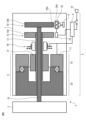
- the primary encoder 15 and the secondary encoder 25 are equipped with rotating disks 15A and 25A, respectively.
- the controller 9 drives and controls the motor 10, and performs a positioning operation to position the link 2 at a target position relative to the link 1. Furthermore, the built-in brake 50 provided on the outer surface of the motor shaft 13 is activated in response to an instruction from the controller 9, and brakes the motor shaft 13. Furthermore, the controller 9 also serves to energize the primary encoder 15 and secondary encoder 25 via the external main power supply 19 when the robot 3 equipped with the links 1 and 2 is in operation.
- the circuit in the detection unit 16 and the first circuit 26a and second circuit 26b in the detection unit 26 are driven by the current supplied from the main power supply 19.
- the first circuit 26a and the second circuit 26b are electrically connected to each other, and the multi-rotation information PB2 of the second circuit 26b can be sent to the first circuit 26a. Therefore, when the robot 3 is disconnected from the main power supply 19 for an extended period of time, even if the motor 10 rotates more than once, that information is detected as multi-rotation information PB2 and sent to the first circuit 26a. Therefore, even in such a case, the first circuit 26a can create an absolute position PA2 that takes into account the multi-rotation information PB2. Similarly, the detection unit 16 can create an absolute position PA1 that takes into account the multi-rotation information PB2.
- the secondary encoder 25 performs detection intermittently at a lower frequency than when current is supplied to the secondary encoder from the outside. In other words, in FIG. 3, the frequency of detection is reduced to suppress the current consumption of the spare battery 8.
- the intermittent period T between the count timings is obtained as shown in the following formula (2). T ⁇ /2 ⁇ v (2) As described above, by setting the intermittent period T to the above value greater than zero, it is possible to reduce the count timing, and therefore reduce the current consumption of the spare battery 8. When the maximum value of the intermittent period T is used, the count timing can be reduced to the greatest extent, and as a result, the current consumption of the spare battery 8 can be further reduced.
- the solid lines in FIG. 5 indicate the case where the spare battery 8 is a primary battery, i.e., a non-rechargeable battery.
- the dashed lines in FIG. 5 indicate the case where the spare battery 8 is a secondary battery, i.e., a rechargeable battery.
- the spare battery 8 is a primary battery.
- the encoders 15, 25 are operated by the main power supply 19.
- the spare battery 8 itself is not used, so the charge level of the spare battery 8 remains at 100%.
- the spare battery 8 is used, and therefore the charge level of the spare battery 8 decreases.
- the charge level of the spare battery 8 reaches zero, and the spare battery 8 needs to be replaced relatively frequently.
- Machines (Robots) 5 Position detection system 6 Actuator 8 Battery 9 Controller 10 Motor 11 Stator 12 Rotor 13 Motor shaft 15 Primary encoder 16 Detection unit 19 Main power supply 19 20: reducer 23: output shaft 25: secondary encoder 26: detector 26a: first circuit 26b: second circuit 50: built-in brake
Landscapes
- Physics & Mathematics (AREA)
- General Physics & Mathematics (AREA)
- Transmission And Conversion Of Sensor Element Output (AREA)
Priority Applications (3)
| Application Number | Priority Date | Filing Date | Title |
|---|---|---|---|
| JP2024568670A JPWO2024147182A1 (https=) | 2023-01-05 | 2023-01-05 | |
| PCT/JP2023/000080 WO2024147182A1 (ja) | 2023-01-05 | 2023-01-05 | 位置検出システムおよびアクチュエータ |
| TW112147189A TW202428408A (zh) | 2023-01-05 | 2023-12-05 | 位置檢測系統及致動器 |
Applications Claiming Priority (1)
| Application Number | Priority Date | Filing Date | Title |
|---|---|---|---|
| PCT/JP2023/000080 WO2024147182A1 (ja) | 2023-01-05 | 2023-01-05 | 位置検出システムおよびアクチュエータ |
Publications (1)
| Publication Number | Publication Date |
|---|---|
| WO2024147182A1 true WO2024147182A1 (ja) | 2024-07-11 |
Family
ID=91803722
Family Applications (1)
| Application Number | Title | Priority Date | Filing Date |
|---|---|---|---|
| PCT/JP2023/000080 Ceased WO2024147182A1 (ja) | 2023-01-05 | 2023-01-05 | 位置検出システムおよびアクチュエータ |
Country Status (3)
| Country | Link |
|---|---|
| JP (1) | JPWO2024147182A1 (https=) |
| TW (1) | TW202428408A (https=) |
| WO (1) | WO2024147182A1 (https=) |
Citations (10)
| Publication number | Priority date | Publication date | Assignee | Title |
|---|---|---|---|---|
| JPH05248893A (ja) * | 1992-03-05 | 1993-09-28 | Matsushita Electric Ind Co Ltd | バックアップ式絶対位置エンコーダ |
| JPH062115U (ja) * | 1992-06-19 | 1994-01-14 | ヤマハ株式会社 | 磁気式検出装置 |
| JPH0723225U (ja) * | 1993-10-04 | 1995-04-25 | 株式会社ニコン | 多回転アブソリュートエンコーダ |
| JP2004239737A (ja) * | 2003-02-05 | 2004-08-26 | Tokai Rika Co Ltd | 回転角度検出装置及び回転角度検出方法 |
| WO2008105217A1 (ja) * | 2007-02-26 | 2008-09-04 | Kabushiki Kaisha Yaskawa Denki | 絶対値エンコーダ装置および多回転検出方法 |
| WO2015137040A1 (ja) * | 2014-03-14 | 2015-09-17 | ソニー株式会社 | ロボットアーム装置、ロボットアーム制御方法及びプログラム |
| WO2017126339A1 (ja) * | 2016-01-18 | 2017-07-27 | 株式会社ニコン | エンコーダ装置、駆動装置、ステージ装置、及びロボット装置 |
| WO2019159311A1 (ja) * | 2018-02-16 | 2019-08-22 | 株式会社五十嵐電機製作所 | Dcモータの制御装置 |
| JP2020193942A (ja) * | 2019-05-30 | 2020-12-03 | 日本電産株式会社 | 回転位置検出装置、回転位置検出方法、及び回転位置検出プログラム |
| JP2021063732A (ja) * | 2019-10-15 | 2021-04-22 | ファナック株式会社 | 補助電源装置及び産業機械 |
Family Cites Families (4)
| Publication number | Priority date | Publication date | Assignee | Title |
|---|---|---|---|---|
| JP4161248B2 (ja) * | 2002-02-27 | 2008-10-08 | 株式会社安川電機 | 複合形検出器 |
| JP2011211791A (ja) * | 2010-03-29 | 2011-10-20 | Toshiba Mach Co Ltd | バックアップ電源装置及び電力出力方法 |
| JP6772013B2 (ja) * | 2016-09-28 | 2020-10-21 | キヤノン株式会社 | ロボットアーム、ロボット制御装置、およびロボットシステム |
| JP2021076587A (ja) * | 2019-10-31 | 2021-05-20 | 株式会社ニコン | エンコーダ装置、その使用方法、その位置決め方法、及び位置検出方法 |
-
2023
- 2023-01-05 WO PCT/JP2023/000080 patent/WO2024147182A1/ja not_active Ceased
- 2023-01-05 JP JP2024568670A patent/JPWO2024147182A1/ja active Pending
- 2023-12-05 TW TW112147189A patent/TW202428408A/zh unknown
Patent Citations (10)
| Publication number | Priority date | Publication date | Assignee | Title |
|---|---|---|---|---|
| JPH05248893A (ja) * | 1992-03-05 | 1993-09-28 | Matsushita Electric Ind Co Ltd | バックアップ式絶対位置エンコーダ |
| JPH062115U (ja) * | 1992-06-19 | 1994-01-14 | ヤマハ株式会社 | 磁気式検出装置 |
| JPH0723225U (ja) * | 1993-10-04 | 1995-04-25 | 株式会社ニコン | 多回転アブソリュートエンコーダ |
| JP2004239737A (ja) * | 2003-02-05 | 2004-08-26 | Tokai Rika Co Ltd | 回転角度検出装置及び回転角度検出方法 |
| WO2008105217A1 (ja) * | 2007-02-26 | 2008-09-04 | Kabushiki Kaisha Yaskawa Denki | 絶対値エンコーダ装置および多回転検出方法 |
| WO2015137040A1 (ja) * | 2014-03-14 | 2015-09-17 | ソニー株式会社 | ロボットアーム装置、ロボットアーム制御方法及びプログラム |
| WO2017126339A1 (ja) * | 2016-01-18 | 2017-07-27 | 株式会社ニコン | エンコーダ装置、駆動装置、ステージ装置、及びロボット装置 |
| WO2019159311A1 (ja) * | 2018-02-16 | 2019-08-22 | 株式会社五十嵐電機製作所 | Dcモータの制御装置 |
| JP2020193942A (ja) * | 2019-05-30 | 2020-12-03 | 日本電産株式会社 | 回転位置検出装置、回転位置検出方法、及び回転位置検出プログラム |
| JP2021063732A (ja) * | 2019-10-15 | 2021-04-22 | ファナック株式会社 | 補助電源装置及び産業機械 |
Also Published As
| Publication number | Publication date |
|---|---|
| TW202428408A (zh) | 2024-07-16 |
| JPWO2024147182A1 (https=) | 2024-07-11 |
Similar Documents
| Publication | Publication Date | Title |
|---|---|---|
| JP5645423B2 (ja) | 回転駆動装置及びロボットアーム | |
| CN101583852B (zh) | 绝对值编码器装置及多转检测方法 | |
| US12011810B2 (en) | Technique for controlling motor in electric power tool | |
| US9772622B2 (en) | Motor control system provided with function to detect abnormal braking | |
| US20190163161A1 (en) | Machine tool controller | |
| US10442050B2 (en) | Rotary table device and method of controlling the rotary table device | |
| CN103926849A (zh) | 修正齿隙的电动机控制装置 | |
| EP3956107A1 (en) | Overload control for a power tool | |
| JP6731583B2 (ja) | モータ制御装置 | |
| CN105527928A (zh) | 机床的控制装置以及控制方法 | |
| JP2019519388A (ja) | 反力が制御された電気パルス工具 | |
| WO2024147182A1 (ja) | 位置検出システムおよびアクチュエータ | |
| JP4282631B2 (ja) | テーブル形式データで運転を行う数値制御装置 | |
| CN101651444B (zh) | 电动机控制器 | |
| JP2023166105A (ja) | 作業機 | |
| WO2023053456A1 (ja) | バックアップ回路を有するエンコーダ | |
| JP2023071389A (ja) | 電動作業機 | |
| JP7021045B2 (ja) | シフトレンジ制御装置 | |
| JP5367783B2 (ja) | 旋回用電動発電機を備えたショベル | |
| JP5581100B2 (ja) | モータの磁極位置補正方法 | |
| JP2019013990A (ja) | インパクト回転工具 | |
| CN104520066A (zh) | 扭矩控制装置 | |
| JP2007192785A (ja) | 絶対位置検出装置付き電動サーボシリンダ | |
| CN109286352A (zh) | 伺服电动机控制装置 | |
| CN100430545C (zh) | 快速运转的针织机的工作方法 |
Legal Events
| Date | Code | Title | Description |
|---|---|---|---|
| 121 | Ep: the epo has been informed by wipo that ep was designated in this application |
Ref document number: 23914674 Country of ref document: EP Kind code of ref document: A1 |
|
| WWE | Wipo information: entry into national phase |
Ref document number: 2024568670 Country of ref document: JP |
|
| NENP | Non-entry into the national phase |
Ref country code: DE |
|
| 122 | Ep: pct application non-entry in european phase |
Ref document number: 23914674 Country of ref document: EP Kind code of ref document: A1 |