WO2024142342A1 - データ収集装置、データ収集方法、データ収集プログラム、切削工具、およびデータ収集システム - Google Patents
データ収集装置、データ収集方法、データ収集プログラム、切削工具、およびデータ収集システム Download PDFInfo
- Publication number
- WO2024142342A1 WO2024142342A1 PCT/JP2022/048439 JP2022048439W WO2024142342A1 WO 2024142342 A1 WO2024142342 A1 WO 2024142342A1 JP 2022048439 W JP2022048439 W JP 2022048439W WO 2024142342 A1 WO2024142342 A1 WO 2024142342A1
- Authority
- WO
- WIPO (PCT)
- Prior art keywords
- cutting tool
- information
- unit
- data
- data collection
- Prior art date
- Legal status (The legal status is an assumption and is not a legal conclusion. Google has not performed a legal analysis and makes no representation as to the accuracy of the status listed.)
- Ceased
Links
Images








Classifications
-
- G—PHYSICS
- G05—CONTROLLING; REGULATING
- G05B—CONTROL OR REGULATING SYSTEMS IN GENERAL; FUNCTIONAL ELEMENTS OF SUCH SYSTEMS; MONITORING OR TESTING ARRANGEMENTS FOR SUCH SYSTEMS OR ELEMENTS
- G05B19/00—Program-control systems
- G05B19/02—Program-control systems electric
- G05B19/18—Numerical control [NC], i.e. automatically operating machines, in particular machine tools, e.g. in a manufacturing environment, so as to execute positioning, movement or co-ordinated operations by means of program data in numerical form
- G05B19/406—Numerical control [NC], i.e. automatically operating machines, in particular machine tools, e.g. in a manufacturing environment, so as to execute positioning, movement or co-ordinated operations by means of program data in numerical form characterised by monitoring or safety
- G05B19/4065—Monitoring tool breakage, life or condition
-
- G—PHYSICS
- G05—CONTROLLING; REGULATING
- G05B—CONTROL OR REGULATING SYSTEMS IN GENERAL; FUNCTIONAL ELEMENTS OF SUCH SYSTEMS; MONITORING OR TESTING ARRANGEMENTS FOR SUCH SYSTEMS OR ELEMENTS
- G05B19/00—Program-control systems
- G05B19/02—Program-control systems electric
- G05B19/18—Numerical control [NC], i.e. automatically operating machines, in particular machine tools, e.g. in a manufacturing environment, so as to execute positioning, movement or co-ordinated operations by means of program data in numerical form
- G05B19/4093—Numerical control [NC], i.e. automatically operating machines, in particular machine tools, e.g. in a manufacturing environment, so as to execute positioning, movement or co-ordinated operations by means of program data in numerical form characterised by part programming, e.g. entry of geometrical information as taken from a technical drawing, combining this with machining and material information to obtain control information, named part program, for the NC machine
- G05B19/40937—Numerical control [NC], i.e. automatically operating machines, in particular machine tools, e.g. in a manufacturing environment, so as to execute positioning, movement or co-ordinated operations by means of program data in numerical form characterised by part programming, e.g. entry of geometrical information as taken from a technical drawing, combining this with machining and material information to obtain control information, named part program, for the NC machine concerning programming of machining or material parameters, pocket machining
- G05B19/40938—Tool management
-
- B—PERFORMING OPERATIONS; TRANSPORTING
- B23—MACHINE TOOLS; METAL-WORKING NOT OTHERWISE PROVIDED FOR
- B23B—TURNING; BORING
- B23B2260/00—Details of constructional elements
- B23B2260/128—Sensors
-
- B—PERFORMING OPERATIONS; TRANSPORTING
- B23—MACHINE TOOLS; METAL-WORKING NOT OTHERWISE PROVIDED FOR
- B23B—TURNING; BORING
- B23B29/00—Holders for non-rotary cutting tools; Boring bars or boring heads; Accessories for tool holders
- B23B29/24—Tool holders for a plurality of cutting tools, e.g. turrets
-
- G—PHYSICS
- G05—CONTROLLING; REGULATING
- G05B—CONTROL OR REGULATING SYSTEMS IN GENERAL; FUNCTIONAL ELEMENTS OF SUCH SYSTEMS; MONITORING OR TESTING ARRANGEMENTS FOR SUCH SYSTEMS OR ELEMENTS
- G05B2219/00—Program-control systems
- G05B2219/30—Nc systems
- G05B2219/37—Measurements
- G05B2219/37252—Life of tool, service life, decay, wear estimation
-
- G—PHYSICS
- G05—CONTROLLING; REGULATING
- G05B—CONTROL OR REGULATING SYSTEMS IN GENERAL; FUNCTIONAL ELEMENTS OF SUCH SYSTEMS; MONITORING OR TESTING ARRANGEMENTS FOR SUCH SYSTEMS OR ELEMENTS
- G05B2219/00—Program-control systems
- G05B2219/30—Nc systems
- G05B2219/49—Nc machine tool, till multiple
- G05B2219/49304—Tool identification, code
-
- G—PHYSICS
- G05—CONTROLLING; REGULATING
- G05B—CONTROL OR REGULATING SYSTEMS IN GENERAL; FUNCTIONAL ELEMENTS OF SUCH SYSTEMS; MONITORING OR TESTING ARRANGEMENTS FOR SUCH SYSTEMS OR ELEMENTS
- G05B2219/00—Program-control systems
- G05B2219/30—Nc systems
- G05B2219/50—Machine tool, machine tool null till machine tool work handling
- G05B2219/50338—Tool with rom chip
Definitions
- Patent Document 1 In machine tools that use cutting tools, it has been proposed to provide a sensor on the cutting tool to monitor the condition of the cutting tool (Patent Document 1).
- the sensor wirelessly sends sensor data to a data collection device.
- the data collection device accumulates this sensor data and displays it on a screen as needed. Based on the measurement results of the workpiece's machining condition thus obtained, the user can set machining conditions and monitor the cutting tool for abnormalities.
- Cutting tools are often attached to and detached from a device called a turret. For this reason, a battery installed inside the cutting tool body is used as the power source for the cutting tool's sensors and wireless transmission module.
- a data collection device includes an information acquisition unit that acquires information identifying the mounting unit to which the cutting tool used by the machine tool is attached from a machine tool that has multiple mounting units to which multiple cutting tools can be attached and switches between the multiple cutting tools to be used for machining a workpiece, and an information storage unit that stores the information regarding the mounting unit to which a first cutting tool is attached, and the first cutting tool has a sensor that detects the state of the first cutting tool and an output unit that outputs data output by the sensor, and further includes a data receiving unit that executes or stops receiving the data from the first cutting tool according to whether or not the information obtained by the information acquisition unit matches the information regarding the mounting unit to which the first cutting tool is attached.
- the data collection device can collect data output by the sensor from the new cutting tool. Also, if communication with the new cutting tool is not possible, data collection can be stopped.
- the first cutting tool is not being used for machining in the machine tool, it is not necessary to check the sensor output in the first cutting tool or to transmit the sensor output to the outside.
- a data collection device can be provided that solves the problems that arise from high sampling rates.
- the present invention can be realized not only as a data collection device equipped with such characteristic processing units, but also as a data collection method having such characteristic processing steps, or as a program for causing a computer to execute such steps. It can also be realized as a semiconductor integrated circuit that realizes part or all of the data collection device, or as a data collection system that includes the data collection device.
- FIG. 1 is a diagram showing a schematic functional configuration of a machine tool system 10 according to the present disclosure.
- FIG. 2 is a diagram showing a schematic configuration of a machine tool system according to the first embodiment of the present disclosure.
- FIG. 3 is a perspective view showing a configuration of a cutting tool used in the machine tool system according to the first embodiment of the present disclosure.
- FIG. 4 is a block diagram showing the configuration of a data transmitter used in the cutting tool shown in FIG.
- FIG. 5 is a block diagram showing a schematic configuration of the control unit shown in FIG.
- FIG. 6 is a schematic diagram showing a turret used in the processing section shown in FIG.
- FIG. 7 is a block diagram showing a schematic configuration of a processor of the control unit shown in FIG. FIG.
- FIG. 8 is a block diagram showing the configuration of the data collecting device shown in FIG.
- FIG. 9 is a diagram showing a schematic configuration of a memory area in the RAM (Random Access Memory) shown in FIG.
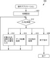
- FIG. 10 is a flowchart representing a control structure of a program constituting an operating application executed by the data collection apparatus shown in FIG. 2 for collecting data from a cutting tool.
- FIG. 11 is a diagram showing a screen configuration for inputting the corresponding relationship between the identification name of a cutting tool and its turret number in the application shown in FIG.
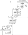
- FIG. 12 is a flowchart representing a control structure of a program for implementing the data collection process started in the data collection device by the program shown in FIG. FIG.
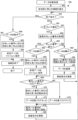
- FIG. 13 is a flowchart showing a control structure of a program executed by the cutting tool shown in FIG.
- FIG. 14 is a flowchart showing a control structure of a program executed by the processor shown in FIG. 5 in the first embodiment of the present disclosure.
- FIG. 15 is a flowchart showing a control structure of a program executed by the processor shown in FIG. 5 in the second embodiment of the present disclosure.
- FIG. 16 is a flowchart showing a control structure of a program executed by the data collection device in the second embodiment of the present disclosure.
- FIG. 17 is a flowchart showing a control structure of a program executed by the cutting tool in the third embodiment of this disclosure.
- FIG. 18 is a block diagram showing a control configuration of a program executed by the data collecting device in the third embodiment of the present disclosure.
- FIG. 19 is a block diagram showing a configuration of a modified example of the control unit shown in FIG.
- the data collection device can collect data output by the sensor from the new cutting tool. Also, if communication with the new cutting tool is not possible, data collection can be stopped.
- the first cutting tool is not being used for machining in the machine tool, it is not necessary to check the sensor output in the first cutting tool or to transmit the sensor output to the outside.
- a data collection device can be provided that solves the problems that arise from high sampling rates.
- the information acquisition unit may repeatedly acquire the information at time intervals shorter than the time required for the machine tool to start and finish changing the cutting tool.
- the information acquisition unit can know whether the first cutting tool has started to be used or whether the cutting tool has been changed from the first cutting tool that had been used until then to another cutting tool, based on time intervals shorter than the time required for the machine tool to start and finish changing the cutting tool.
- the data collection device can reliably know the change of cutting tool before the cutting tool is used for machining in the next task.
- the machine tool may have a function of outputting the information identifying the cutting tool when the cutting tool used by the machine tool is switched, and the information acquisition unit may acquire the information from the machine tool when the cutting tool used by the machine tool is switched.
- the acquired information can know information about the replaced cutting tool. Therefore, when the cutting tool is replaced, the data collection device can reliably know that the cutting tool has been replaced, and data collection can be reliably stopped and started. There is no longer a need to constantly inquire of the machine tool about the cutting tool in use in order to know which cutting tool the machine tool is using, simplifying processing.
- a data collection program is a computer program that causes a computer to function as an information acquisition unit that acquires information identifying the mounting unit to which a cutting tool used by a machine tool is attached from a machine tool that has multiple mounting units capable of mounting multiple cutting tools and that switches between the multiple cutting tools to be used for machining a workpiece, and an information storage unit that stores the information regarding the mounting unit to which a first cutting tool is attached, the first cutting tool having a sensor that detects the state of the first cutting tool and an output unit that outputs data output by the sensor, and the computer program further causes the computer to function as a data receiving unit that executes or stops receiving the data from the first cutting tool depending on whether the information obtained by the information acquisition unit matches the information regarding the mounting unit to which the first cutting tool is attached.
- a specific machine tool system 50 includes a machine tool 64, a data transmitter 72, a data transmitter 74, and a data transmitter 76 of cutting tools inside the machine tool 64, and a data collection system 52 that collects and accumulates sensor information from these data transmitters etc. via wireless communication and displays the data in chronological order in real time.
- Cutting tool 100 3 shows a configuration of a cutting tool 100 having a data transmitter 72.
- the cutting tool 100 includes a head portion 112 to which a cutting insert 116 is fixed, and a cutting insert 116 of the head portion 112.
- the cutting tool 100 includes a head portion 112 and a holder portion 110 fixed on the opposite side to the fixed end.
- the cutting insert 116 has a cutting edge 118 at its tip and is fixed to the head portion 112 by a fixing member 114.
- the holder portion 110 has a top surface 124, a bottom surface 128, a front surface 120, a rear surface 126, and an end surface 122.
- the data collection system 52 includes a wireless communication device 62 that wirelessly communicates with a wireless communication module 154 (see Figure 4) provided on a cutting tool attached to a turret 210 inside the machine tool 64, and is mainly used to receive sensor data from each data transmitter, and a data collection device 60 that accumulates the sensor data received by the wireless communication device 62 and performs processing to display the time series of the sensor data in association with each turning tool.
- a wireless communication device 62 that wirelessly communicates with a wireless communication module 154 (see Figure 4) provided on a cutting tool attached to a turret 210 inside the machine tool 64, and is mainly used to receive sensor data from each data transmitter
- a data collection device 60 that accumulates the sensor data received by the wireless communication device 62 and performs processing to display the time series of the sensor data in association with each turning tool.
- FIG. 9 shows the internal storage areas of RAM 374 for the main variables used by CPU 370 in this embodiment. That is, RAM 374 includes a current turret number storage area 392 that stores the number of the mounting part to which the cutting tool being used by processing unit 200 is attached, and a new turret number storage area 390 that stores the turret number of the mounting part to which the cutting tool to be newly used is attached when the turret is switched. RAM 374 further includes a correspondence table storage area 394 for storing a turret number/cutting tool identifier correspondence table that shows the correspondence between each turret number and the identifier of the cutting tool attached to the mounting part corresponding to that turret number.
- a correspondence table storage area 394 for storing a turret number/cutting tool identifier correspondence table that shows the correspondence between each turret number and the identifier of the cutting tool attached to the mounting part corresponding to that turret number.
- FIG. 10 shows, in the form of a flowchart, a control structure of an operation application started by a user so that data collection device 60 shown in Fig. 2 can collect data from machine tool 64.
- This application basically operates in an interactive format in response to instructions from the user.
- the identification name of the cutting tool referred to here may be, for example, a MAC address assigned to the wireless communication module of each cutting tool, an identifier assigned to the cutting tool when the cutting tool is produced, or a name assigned to the cutting tool so that the user of the cutting tool can easily distinguish it from other cutting tools.
- the identification name of the cutting tool entered in the field column 440 is stored in the correspondence table storage area 394 shown in FIG. 9 in association with the turret number corresponding to the field. If there is no input in field column 440, the cutting tool identifier corresponding to the turret number corresponding to that field column will be blank.
- step 456 in order to obtain the turret number in step 456, it is assumed that the machine tool 64 has a function for outputting the turret number used for machining in response to an external request for the turret number.
- the control unit 70 In order to perform machining, the control unit 70 needs to hold the turret number corresponding to the cutting tool being used. Therefore, it is not particularly difficult to provide this information to the outside.
- This program further includes step 460, which branches the flow of control according to whether sensor data is currently being collected from the cutting tool when the determination in step 458 is positive, step 462, which transmits an instruction to the cutting tool corresponding to the current turret number to suspend measurement by the sensor when the determination in step 460 is positive, and step 464, which follows step 462, which saves the data received and accumulated from the cutting tool up to that point as a file in SSD 376 (see FIG. 8).
- Whether data is being collected can be determined according to whether a data collection flag, which will be described later, is set. In this embodiment, data is saved in a file when measurement is suspended.
- this disclosure is not limited to such an embodiment.
- This program further includes step 482, which branches the control flow according to whether data is currently being collected from the cutting tool currently being used by the control unit 70 for machining when the determination in step 458 is negative, step 484, which receives data from the cutting tool corresponding to the current turret number according to the correspondence table storage area 394 shown in FIG. 9 when the determination in step 482 is positive, step 486, which stores the data received in step 484 in memory, and step 488, which uses the data stored in step 486 to update the display on the monitor 352 using the time series of the latest data and returns control to step 454.
- step 482 is negative, control returns to step 454.
- the program further includes step 496, which terminates the connection with the wireless communication module 154 of each cutting tool and terminates execution of the program 450 when the determination in step 490 is negative, and when the determination in step 490 is positive and steps 492 and 494 are completed.
- FIG. 13 shows a control structure of a program for cutting tool side processing executed by, for example, CPU 152 in Fig. 4.
- this program 500 includes step 510 for initializing each unit of data transmitter 72, step 512 for branching the control flow according to whether or not any instruction has been received from the outside (in this embodiment, data collection device 60 connected via wireless communication device 62), and, when the determination in step 512 is positive, step 522 for branching the control flow according to whether or not the instruction received in step 512 is an instruction to start a measurement process of sensor data (measurement start instruction).
- the measurement flag reset in step 528 is a flag used by CPU 152 to determine whether or not the cutting tool is measuring the sensor output. If the measurement flag is set, it indicates that the cutting tool is measuring the sensor output and transmitting it to data collection device 60, i.e., data collection device 60 is receiving sensor data. If the measurement flag is reset, it indicates that the cutting tool is not measuring the sensor output (is at rest) and is not transmitting data, i.e., data collection device 60 is not receiving sensor data. When the cutting tool is not measuring sensor data, CPU 152 (see FIG. 4) is not performing any substantial processing, and power consumption of CPU 152 is kept low.
- this program includes step 560, which executes an initial process to initialize each part of the hardware immediately after the program is started, and step 562, which branches the flow of control depending on whether or not there is any input from the outside. If the determination in step 562 is negative, control returns to step 562 and waits for an input from the outside. Examples of input from the outside include instructions received from the outside (e.g., data collection device 60) via wireless communication device 204 shown in FIG. 5, instructions entered by the user using operation panel 306, and any notifications output by processing unit 200 as processing progresses.
- the program configuration will be explained, focusing on the process executed by data collection device 60 when it receives a turret number inquiry process executed in step 456 by data collection device 60.
- This program further includes step 564, which, when the determination in step 562 is positive, determines whether the instruction is an instruction to start processing and branches the control flow according to the result, step 566, which sets an in-process flag when the determination in step 564 is positive, and, following step 566, step 568, which starts up the processing unit 200, executes a specified processing program, and returns control to step 562.
- This program further includes step 576, which branches the flow of control depending on whether the input received in step 562 is a query for the turret number from the data collection device 60 when the determination in step 564 is negative; step 578, which reads the turret number, which is the number of the mounting part to which the cutting tool being used is attached, from the turret number storage unit 212 shown in FIG. 5 (effectively RAM 324 shown in FIG. 7) when the determination in step 576 is positive; step 580, which returns the turret number read in step 578 to the data collection device 60 by wireless communication and returns control to step 562; and step 582, which performs some processing according to the instruction received in step 562 and returns control to step 562 when the determination in step 576 is negative.
- the machine tool system 50 (see FIG. 2), the structure of which has been described above, operates as follows. For example, the user first starts the program 400 shown in FIG. 10 in the data collection device 60. Then, the user operates the first button. When the first button is operated, a screen 430 shown in FIG. 11 is displayed on the monitor 352. If a cutting tool having the same function as the cutting tool 100 is mounted on any of the mounting parts of the turret 210, the user uses this screen 430 to input the identification name of the cutting tool in the corresponding field of the field column 440 as an identifier corresponding to the turret number of the mounting part.
- step 468 determines whether the determination in step 468 is negative. Therefore, control proceeds to step 474, where the data collection flag is cleared.
- step 480 the data display is updated based on the data collected by the processing up to step 464, and control returns to step 454.
- step 458 is negative.
- the data collection flag is cleared in step 474. Therefore, the determination in step 482 is negative, and control returns to step 474. In other words, unless the cutting tool is changed to a new one, collection of sensor data from the cutting tool is not performed.
- step 454 it is determined whether the data collection process is running or not. This determination is made based on whether the data collection flag is set or reset. If the data collection flag is set, in step 492, an instruction to suspend the transmission of sensor data is issued to the cutting tool corresponding to the current turret number. In step 494, the sensor data received up to that point is saved as a file. In step 496, an instruction to end the connection is issued to all cutting tools that have the function of transmitting sensor data, and execution of program 450 is terminated. As a result, each cutting tool also stops functioning.
- Second embodiment A Configuration
- step 456 is repeatedly executed to detect that the cutting tool used for machining has been changed.
- this disclosure is not limited to such an embodiment.
- the machine tool rotates the turret to start machining with a new cutting tool
- the turret number corresponding to the mounting on which the cutting tool is mounted is transmitted to the data collection device.
- the data collection device 60 receives a new turret number from the machine tool, it switches the cutting tool with which it communicates.
- the machine tool 64 does not notify the data collection device 60 of the turret number in response to a request from the data collection device 60, but rather notifies the data collection device 60 of the turret number corresponding to the mounting unit to which the new cutting tool is attached in response to switching of the cutting tool used by the processing unit 200 (FIG. 5). With this configuration, the same effect as in the first embodiment can be obtained.
- control structure of program 650 executed by computer 350 (FIG. 8) of data collection device 60 shown in FIG. 2 is shown in FIG. 16.
- This program 650 differs from program 450, the control structure of which is shown in FIG. 12, in that, instead of step 456 in FIG. 12, it includes step 662, which branches the control flow according to whether the instruction received in step 660 is a notification of a turret number from machine tool 64 when the determination in step 454 is negative. If the determination in step 662 is positive, control proceeds to step 458. If the determination in step 662 is negative, control proceeds to step 482.
- program 650 is identical to program 450 shown in FIG. 12.
- the operation of the data collection device 60 in the machine tool system 50 according to the second embodiment is almost the same as that in the first embodiment.
- step 458 is executed via the path of steps 454 and 662 shown in FIG. 16.
- the machine tool system 50 according to the second embodiment is the same as that in the first embodiment.
- the cutting tool when a cutting tool having a sensor data transmission function is used for machining in the machine tool 64, the cutting tool transmits sensor data, and the data collection device 60 receives center data from each cutting tool.
- the cutting tool When such a cutting tool is not used for machining, the cutting tool does not transmit sensor data, and the data collection device 60 does not receive sensor data. Therefore, the power used in the cutting tool can be saved.
- the battery replacement period is also extended. As a result, problems caused by a high sampling rate can be solved.
- the connection between each cutting tool and the data collection device 60 is maintained from the time when the data collection device 60 is instructed to start the data collection process until it is instructed to end it.
- the machine tool 64 when there is a change in the turret number corresponding to the cutting tool being used in the machine tool 64, the machine tool 64 notifies the data collection device 60 of the turret number.
- this disclosure is not limited to such an embodiment.
- the output of an acceleration sensor provided in the cutting tool 100 is used to determine whether the turret 210 has been rotated, and when it is determined that the turret 210 has been rotated, the information is notified to the data collection device 60.
- the data collection device 60 receives this notification from the cutting tool 100, it inquires of the machine tool 64 about the turret number.
- control structure of the program executed by the machine tool 64 is similar to that of the third embodiment shown in FIG. 15.
- step 714 for branching the flow of control according to whether the value of acceleration calculated based on the output of the acceleration sensor 136 obtained in step 712 is greater than a predetermined first threshold value
- step 716 for branching the flow of control according to whether the value of velocity calculated based on the output of the acceleration sensor 136 is greater than a predetermined second threshold value when the determination in step 714 is positive
- step 718 for sending a notification to the data collection device 60 indicating that it is time to read the turret number and returning control to step 712 when the determination in step 716 is positive.
- step 714 If the determination in step 714 is negative, or if the determination in step 716 is negative, control returns to step 712. In other words, in this case, a notification indicating the timing of reading the turret number, as in step 718, is not sent.
- the data collection device 60 executes a program 750 whose control structure is shown in FIG. 18.
- Program 750 differs from program 450 whose control structure is shown in FIG. 12 in that, when the determination in step 454 shown in FIG. 12 is negative, it includes step 760, which branches the flow of control depending on whether the input received in step 454 is a notification from the cutting tool 100 or the like indicating that it is time to read the turret number. If the determination in step 760 is positive, control proceeds to step 456. If the determination in step 760 is negative, control proceeds to step 482.
- control structure of program 750 is the same as that of program 650 shown in FIG. 16.
- the third embodiment is characterized in that the cutting tool 100 detects whether the turret 210 (FIGS. 5 and 6) has rotated from the output of the acceleration sensor 136, and does not transmit a notification indicating the timing of reading the turret number to the data collection device 60 only when it is determined that the turret 210 has rotated. As a result, the data collection device 60 does not send a request to transmit the turret number to the machine tool 64 (FIG. 2) unless it receives a notification indicating the timing of reading the turret number from the cutting tool 100. In particular, at the start and end of the rotation of the turret 210, the absolute value of the acceleration detected by the cutting tool 100 becomes larger than a predetermined threshold value.
- the data collection device 60 transmits a request to transmit the turret number to the machine tool 64 only when the turret 210 actually starts and ends its rotation. Unlike the first embodiment, the data collecting device 60 does not repeatedly issue a request to the machine tool 64 to transmit the turret number at short intervals. As a result, the third embodiment has the effect of reducing part of the processing of the data collecting device 60 and the processing of the machine tool 64.
- the cutting tool 100 transmits a read notification of the turret number only when the turret 210 starts rotating and when it stops rotating. This makes it possible to avoid large power consumption of the cutting tool 100 and the like.
- this third embodiment also solves the problem caused by a high sampling rate. Furthermore, the connection between each cutting tool and the data collection device 60 is maintained from the time the data collection device 60 is instructed to start the data collection process until it is instructed to end it. As a result, when data collection is started from a specific cutting tool, there is no need to establish a new connection between the cutting tool and the data collection device 60. Therefore, even when the cutting tool is switched, the possibility that the data collection device 60 will fail to receive the sensor data that is initially transmitted from the cutting tool can be reduced. Furthermore, in this third embodiment, like the second embodiment, there is no need for the data collection device 60 to repeatedly inquire of the turret number from the machine tool 64. As a result, the processing in the data collection device 60 and the machine tool 64 can be simplified.
- the machine tool 64 used in the above embodiment uses a control unit 70 having a wireless communication device 204 as shown in Fig. 5. However, this disclosure is not limited to such an embodiment.
- the machine tool 64 may use a control unit 800 shown in Fig. 19 instead of the control unit 70.
- the control unit 800 differs from the control unit 70 shown in FIG. 5 in that it includes a wired communication device 810 connected to the network via a communication line such as a cable, instead of the wireless communication device 204 shown in FIG. 5.
- the control unit 800 is the same as the control unit 70.
- the machine tool 64 can communicate stably with the data collection device 60 even in an electrically noisy environment such as a machining site.
- the wired communication device 810 is connected to the network via a communication line and communicates with the outside via the network, but this disclosure is not limited to such an embodiment.
- the wired communication device 810 may be directly connected to the data collection device 60 via a communication line.
- Each process (each function) of the above-mentioned embodiment is realized by a processing circuit (circuitry) including one or more processors.
- the processing circuit may be composed of an integrated circuit in which one or more memories, various analog circuits, and various digital circuits are combined in addition to the one or more processors.
- the one or more memories store programs (instructions) that cause the one or more processors to execute each of the above processes.
- the one or more processors may execute each of the above processes according to the programs read from the one or more memories, or may execute each of the above processes according to a logic circuit designed in advance to execute each of the above processes.
- the processor may be any of various processors suitable for computer control, such as a CPU, a GPU (Graphics Processing Unit), a DSP (Digital Signal Processor), an FPGA (Field-Programmable Gate Array), or an ASIC (Application Specific Integrated Circuit).
- the physically separated processors may cooperate with each other to execute the above processes.
- the processors mounted on each of the physically separated computers may cooperate with each other via a network such as a LAN (Local Area Network), a WAN (Wide Area Network), or the Internet to execute the above processes.
- the program may be installed in the memory from an external server device or the like via the network, or may be distributed in a state stored in a recording medium such as a CD-ROM (Compact Disc Read-Only Memory), a DVD-ROM (Digital Versatile Disc Read-Only Memory), or a semiconductor memory, and may be installed in the memory from the recording medium.
- a recording medium such as a CD-ROM (Compact Disc Read-Only Memory), a DVD-ROM (Digital Versatile Disc Read-Only Memory), or a semiconductor memory, and may be installed in the memory from the recording medium.
Landscapes
- Engineering & Computer Science (AREA)
- Manufacturing & Machinery (AREA)
- Physics & Mathematics (AREA)
- Human Computer Interaction (AREA)
- General Physics & Mathematics (AREA)
- Automation & Control Theory (AREA)
- Geometry (AREA)
- Numerical Control (AREA)
- Machine Tool Sensing Apparatuses (AREA)
- Cutting Tools, Boring Holders, And Turrets (AREA)
Priority Applications (4)
| Application Number | Priority Date | Filing Date | Title |
|---|---|---|---|
| PCT/JP2022/048439 WO2024142342A1 (ja) | 2022-12-28 | 2022-12-28 | データ収集装置、データ収集方法、データ収集プログラム、切削工具、およびデータ収集システム |
| EP22970130.5A EP4644042A4 (en) | 2022-12-28 | 2022-12-28 | DATA COLLECTION DEVICE, DATA COLLECTION METHOD, DATA COLLECTION PROGRAM, CUTTING TOOL AND DATA COLLECTION SYSTEM |
| JP2023533657A JP7355284B1 (ja) | 2022-12-28 | 2022-12-28 | データ収集装置、データ収集方法、データ収集プログラム、切削工具、およびデータ収集システム |
| CN202280102142.1A CN120265427A (zh) | 2022-12-28 | 2022-12-28 | 数据收集装置、数据收集方法、数据收集程序、切削工具以及数据收集系统 |
Applications Claiming Priority (1)
| Application Number | Priority Date | Filing Date | Title |
|---|---|---|---|
| PCT/JP2022/048439 WO2024142342A1 (ja) | 2022-12-28 | 2022-12-28 | データ収集装置、データ収集方法、データ収集プログラム、切削工具、およびデータ収集システム |
Publications (1)
| Publication Number | Publication Date |
|---|---|
| WO2024142342A1 true WO2024142342A1 (ja) | 2024-07-04 |
Family
ID=88198263
Family Applications (1)
| Application Number | Title | Priority Date | Filing Date |
|---|---|---|---|
| PCT/JP2022/048439 Ceased WO2024142342A1 (ja) | 2022-12-28 | 2022-12-28 | データ収集装置、データ収集方法、データ収集プログラム、切削工具、およびデータ収集システム |
Country Status (4)
| Country | Link |
|---|---|
| EP (1) | EP4644042A4 (https=) |
| JP (1) | JP7355284B1 (https=) |
| CN (1) | CN120265427A (https=) |
| WO (1) | WO2024142342A1 (https=) |
Families Citing this family (1)
| Publication number | Priority date | Publication date | Assignee | Title |
|---|---|---|---|---|
| IT201900011289A1 (it) * | 2019-07-09 | 2021-01-09 | M T S R L | Modulo porta-utensile |
Citations (6)
| Publication number | Priority date | Publication date | Assignee | Title |
|---|---|---|---|---|
| JP2010234464A (ja) * | 2009-03-31 | 2010-10-21 | Kondo Seisakusho:Kk | タレット式切削工具の異常検出方法 |
| JP5822441B2 (ja) * | 2010-07-13 | 2015-11-24 | 株式会社幸和電熱計器 | 切削加工評価装置 |
| JP2020104257A (ja) * | 2018-12-25 | 2020-07-09 | 日立金属株式会社 | 切削工具の異常検知装置、および異常検知方法 |
| WO2021025010A1 (ja) * | 2019-08-05 | 2021-02-11 | 京セラ株式会社 | センサシステム、無線端末及び無線通信機器 |
| WO2021029202A1 (ja) * | 2019-08-09 | 2021-02-18 | 住友電気工業株式会社 | 切削工具、切削工具用ホルダ、工具システムおよび通信方法 |
| WO2021251072A1 (ja) | 2020-06-08 | 2021-12-16 | 住友電気工業株式会社 | 切削工具、工具システムおよび通信制御方法 |
Family Cites Families (1)
| Publication number | Priority date | Publication date | Assignee | Title |
|---|---|---|---|---|
| JP7160602B2 (ja) * | 2018-08-28 | 2022-10-25 | ファナック株式会社 | 工具識別装置及び工具識別システム |
-
2022
- 2022-12-28 CN CN202280102142.1A patent/CN120265427A/zh active Pending
- 2022-12-28 WO PCT/JP2022/048439 patent/WO2024142342A1/ja not_active Ceased
- 2022-12-28 EP EP22970130.5A patent/EP4644042A4/en active Pending
- 2022-12-28 JP JP2023533657A patent/JP7355284B1/ja active Active
Patent Citations (6)
| Publication number | Priority date | Publication date | Assignee | Title |
|---|---|---|---|---|
| JP2010234464A (ja) * | 2009-03-31 | 2010-10-21 | Kondo Seisakusho:Kk | タレット式切削工具の異常検出方法 |
| JP5822441B2 (ja) * | 2010-07-13 | 2015-11-24 | 株式会社幸和電熱計器 | 切削加工評価装置 |
| JP2020104257A (ja) * | 2018-12-25 | 2020-07-09 | 日立金属株式会社 | 切削工具の異常検知装置、および異常検知方法 |
| WO2021025010A1 (ja) * | 2019-08-05 | 2021-02-11 | 京セラ株式会社 | センサシステム、無線端末及び無線通信機器 |
| WO2021029202A1 (ja) * | 2019-08-09 | 2021-02-18 | 住友電気工業株式会社 | 切削工具、切削工具用ホルダ、工具システムおよび通信方法 |
| WO2021251072A1 (ja) | 2020-06-08 | 2021-12-16 | 住友電気工業株式会社 | 切削工具、工具システムおよび通信制御方法 |
Non-Patent Citations (1)
| Title |
|---|
| See also references of EP4644042A1 |
Also Published As
| Publication number | Publication date |
|---|---|
| JP7355284B1 (ja) | 2023-10-03 |
| EP4644042A1 (en) | 2025-11-05 |
| EP4644042A4 (en) | 2026-02-18 |
| CN120265427A (zh) | 2025-07-04 |
| JPWO2024142342A1 (https=) | 2024-07-04 |
Similar Documents
| Publication | Publication Date | Title |
|---|---|---|
| JP6836585B2 (ja) | リアルタイム制御システム、リアルタイム制御装置及びシステムの制御方法 | |
| JP5467891B2 (ja) | 情報処理装置、デバッグ装置、デバッグ方法 | |
| JP5218585B2 (ja) | 制御装置およびシステムプログラム | |
| JP6288104B2 (ja) | トレースデータ収集システム、操作端末、及びトレースデータ収集方法 | |
| JP2018096987A (ja) | フラッシュメモリに記憶されたカウント値を持つ測定装置用トリガカウンタ | |
| CN104570932B (zh) | 一种数控系统加工过程数据的采集、转储方法及其系统 | |
| WO2024142342A1 (ja) | データ収集装置、データ収集方法、データ収集プログラム、切削工具、およびデータ収集システム | |
| CN112565332A (zh) | 基于imu的摆动雷达振动和倾角状态监测方法及系统 | |
| JP6822242B2 (ja) | 診断装置、診断システム、診断方法およびプログラム | |
| EP3696626B1 (en) | Communication system, communication method, and program | |
| JP2011039643A (ja) | プログラマブルコントローラ | |
| CN108628252B (zh) | 测量系统、计算机可读介质和控制方法 | |
| US12085904B2 (en) | Engineering device, engineering method, and information storage medium | |
| JP7147805B2 (ja) | 生産システム、データ送信方法、及びプログラム | |
| JP7405307B1 (ja) | センサ異常判定装置、センサ異常判定システム、センサ異常判定方法、コンピュータプログラム、非一時的記憶媒体、および工作機械 | |
| JP2022143423A (ja) | 診断装置、診断システム、診断方法及び診断プログラム | |
| CN202684923U (zh) | 一种基于嵌入式系统的爬行式焊接机器人手持式控制器 | |
| TWI735050B (zh) | 資料儲存裝置、電子設備及可遠端控制電子設備的系統 | |
| WO2025088877A1 (ja) | 制御装置、制御システム、および制御方法 | |
| CN110888598B (zh) | 数据储存装置、电子设备及可远程控制电子设备的系统 | |
| JP4463737B2 (ja) | プログラム開発システム | |
| JPH09305532A (ja) | データ転送方法及びデータ転送装置 | |
| JP2010108202A (ja) | 機器監視制御システム、機器監視制御方法、及び制御プログラム | |
| JPWO2020202437A1 (ja) | 判別装置、判別方法、およびプログラム | |
| CN114415606A (zh) | 控制方法和系统 |
Legal Events
| Date | Code | Title | Description |
|---|---|---|---|
| WWE | Wipo information: entry into national phase |
Ref document number: 2023533657 Country of ref document: JP |
|
| 121 | Ep: the epo has been informed by wipo that ep was designated in this application |
Ref document number: 22970130 Country of ref document: EP Kind code of ref document: A1 |
|
| WWE | Wipo information: entry into national phase |
Ref document number: 202280102142.1 Country of ref document: CN |
|
| WWP | Wipo information: published in national office |
Ref document number: 202280102142.1 Country of ref document: CN |
|
| WWE | Wipo information: entry into national phase |
Ref document number: 2022970130 Country of ref document: EP |
|
| NENP | Non-entry into the national phase |
Ref country code: DE |
|
| ENP | Entry into the national phase |
Ref document number: 2022970130 Country of ref document: EP Effective date: 20250728 |
|
| ENP | Entry into the national phase |
Ref document number: 2022970130 Country of ref document: EP Effective date: 20250728 |
|
| WWP | Wipo information: published in national office |
Ref document number: 2022970130 Country of ref document: EP |