WO2024135165A1 - ユニット - Google Patents
ユニット Download PDFInfo
- Publication number
- WO2024135165A1 WO2024135165A1 PCT/JP2023/041020 JP2023041020W WO2024135165A1 WO 2024135165 A1 WO2024135165 A1 WO 2024135165A1 JP 2023041020 W JP2023041020 W JP 2023041020W WO 2024135165 A1 WO2024135165 A1 WO 2024135165A1
- Authority
- WO
- WIPO (PCT)
- Prior art keywords
- gear
- bearing
- oil passage
- unit
- axis
- Prior art date
- Legal status (The legal status is an assumption and is not a legal conclusion. Google has not performed a legal analysis and makes no representation as to the accuracy of the status listed.)
- Ceased
Links
Images


Classifications
-
- F—MECHANICAL ENGINEERING; LIGHTING; HEATING; WEAPONS; BLASTING
- F16—ENGINEERING ELEMENTS AND UNITS; GENERAL MEASURES FOR PRODUCING AND MAINTAINING EFFECTIVE FUNCTIONING OF MACHINES OR INSTALLATIONS; THERMAL INSULATION IN GENERAL
- F16H—GEARING
- F16H57/00—General details of gearing
- F16H57/02—Gearboxes; Mounting gearing therein
-
- F—MECHANICAL ENGINEERING; LIGHTING; HEATING; WEAPONS; BLASTING
- F16—ENGINEERING ELEMENTS AND UNITS; GENERAL MEASURES FOR PRODUCING AND MAINTAINING EFFECTIVE FUNCTIONING OF MACHINES OR INSTALLATIONS; THERMAL INSULATION IN GENERAL
- F16H—GEARING
- F16H57/00—General details of gearing
- F16H57/04—Features relating to lubrication or cooling or heating
-
- H—ELECTRICITY
- H02—GENERATION; CONVERSION OR DISTRIBUTION OF ELECTRIC POWER
- H02K—DYNAMO-ELECTRIC MACHINES
- H02K7/00—Arrangements for handling mechanical energy structurally associated with dynamo-electric machines, e.g. structural association with mechanical driving motors or auxiliary dynamo-electric machines
- H02K7/10—Structural association with clutches, brakes, gears, pulleys or mechanical starters
- H02K7/116—Structural association with clutches, brakes, gears, pulleys or mechanical starters with gears
Definitions
- the present invention relates to a unit.
- Patent Document 1 discloses a power transmission device for a converted EV (modified electric vehicle).
- the installation space for a unit that includes a rotating electric machine may be limited in advance.
- the unit that includes the rotating electric machine must be installed in the space left after the engine is removed.
- a unit has a rotating electric machine, a first gear connected downstream of the rotating electric machine, a second gear meshing with the first gear, a third gear rotating integrally with the second gear, and a fourth gear meshing with the third gear.
- the fourth gear When viewed in the axial direction, the fourth gear has a portion that overlaps with the rotating electric machine.
- the rotating electric machine and the first gear have the same axis, and the second gear and the third gear have the same axis.
- the rotating electric machine and the fourth gear have misaligned axes.
- the axis of the rotating electric machine and the fourth gear are offset, which removes such restrictions and increases design freedom. Even with the axis of the rotating electric machine offset in this way, it is still possible to miniaturize the unit to a certain extent, such as to the extent necessary for installation in a converted EV.
- FIG. 1 is a schematic diagram of a unit according to this embodiment.
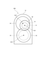
- FIG. 2 is a cross-sectional view of the unit taken along line II-II of FIG.
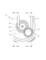
- FIG. 3 is a cross-sectional view of the unit taken along line III-III in FIG.
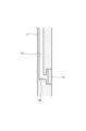
- FIG. 4 is a first explanatory diagram of the first oil passage and the second oil passage.
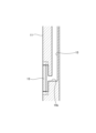
- FIG. 5 is a second explanatory diagram of the first oil passage and the second oil passage.
- FIG. 6 is a third explanatory diagram of the first oil passage and the second oil passage.
- FIG. 7 is a fourth explanatory diagram of the first oil passage and the second oil passage.
- FIG. 8 is a fifth explanatory diagram of the first oil passage and the second oil passage.
- FIG. 1 is a schematic diagram of a unit 100 according to this embodiment.
- FIG. 2 is a cross-sectional view of the unit 100 taken along line II-II in FIG. 1.
- FIG. 3 is a cross-sectional view of the unit 100 taken along line III-III in FIG. 1.
- the unit can also be called, for example, a motor unit (a unit having at least a motor) or a power transmission device (a device having at least a power transmission mechanism).
- a motor is a rotating electric machine having an electric motor function and/or a generator function (at least one of an electric motor function and a generator function).
- a power transmission mechanism is, for example, a gear mechanism and/or a differential gear mechanism.
- a device (unit) having a motor and a power transmission mechanism is included in the concepts of both a motor unit and a power transmission device.
- the unit 100 is mounted on a vehicle.
- the vehicle is a converted EV, and the unit 100 replaces the engine in the base vehicle of the converted EV.
- the application of the unit 100 is not limited to converted EVs, and the unit 100 may be used in other vehicles besides converted EVs.
- the unit 100 is connected to the transmission 2 so that power can be transmitted, and is also connected to the accessory 4 via the accessory pulley 3 so that power can be transmitted.
- the transmission 2, accessory pulley 3, and accessory 4 are from the base vehicle of the converted EV, and are used as is in the converted EV.
- the transmission 2 is, for example, a stepped automatic transmission.
- the accessory 4 is an accessory of the engine of the base vehicle, for example, an alternator. By using an alternator as the accessory 4, it becomes unnecessary to supply power from the EV driving battery to the 12V power supply.
- the accessory 4 may be, for example, an air conditioner compressor or a power steering pump.
- the unit 100 comprises a housing 10, a rotating electric machine 20, and a gear mechanism 30.
- the housing 10 houses the rotating electric machine 20 and the gear mechanism 30.
- the housing 10 can be composed of multiple case members including a cover, etc.
- the housing 10 can also have support wall portions near the II-II cross section position and near the III-III cross section position that support the bearings of the shaft of the gear mechanism 30.
- the rotating electric machine 20 constitutes the driving source of the vehicle, and includes a rotor 21, a stator 22, and a rotating shaft 23.
- the rotor 21 is provided on the outer periphery of the rotating shaft 23, and the stator 22 houses the rotor 21.
- the rotating shaft 23 protrudes from the rotor 21 to one axial side (the transmission 2 side) corresponding to the left side of FIG. 1.
- the gear mechanism 30 includes a first gear 31, a second gear 32, a third gear 33, a fourth gear 34, a fifth gear 35, a sixth gear 36, a long shaft 37, a first output shaft 38, and a second output shaft 39.
- the first gear 31 is arranged on the first axis AX1 together with the rotating electric machine 20.
- the rotating electric machine 20 and the first gear 31 are arranged coaxially with respect to the first axis AX1.
- arranging a plurality of elements (parts, portions, etc.) on the Nth axis (N is a natural number) is synonymous with arranging a plurality of elements coaxially with respect to the Nth axis.
- the second gear 32, the third gear 33, and the fifth gear 35 are arranged on the second axis AX2, and the fourth gear 34 and the sixth gear 36 are arranged on the third axis AX3.
- the first axis AX1, the second axis AX2, and the third axis AX3 all constitute the axes of the unit 100 and extend along the same direction. Therefore, the extension directions of the first axis AX1, the second axis AX2, and the third axis AX3 all correspond to the axial direction of the unit 100.
- the axial direction refers to the axial direction of the rotating shafts of the components that constitute the unit (e.g., a motor, a gear mechanism, or a differential gear mechanism).
- the radial direction of the unit 100 is a direction perpendicular to either the first axis AX1, the second axis AX2, or the third axis AX3.
- the first gear 31 is connected downstream of the rotating electric machine 20.
- the downstream is the power output side, and with respect to the rotating electric machine 20, the rotor 21 and stator 22 that generate power are used as the reference. Therefore, the downstream of the rotating electric machine 20 can be said to be the downstream of the stator 22. While the downstream is the power output side, the upstream is the power input side.
- the first gear 31 is connected downstream of the rotating electric machine 20 so that power can be transmitted.
- the connection may be via other configurations (for example, a clutch or other gear mechanism).
- the first gear 31 is provided on one axial side of the rotor 21 and is integrated with the rotating shaft 23.
- the rotating electric machine 20 and the first gear 31 share the same axis, the first axis AX1.
- the outer diameter of the first gear 31 is set to be smaller than the outer diameter of the rotating electric machine 20.
- the second gear 32 meshes with the first gear 31.
- the second gear 32 has a larger number of teeth than the first gear 31, and together with the first gear 31 constitutes the first reduction mechanism R1.
- the second gear 32 is provided on a long shaft 37.
- the second gear 32 is integrated with the long shaft 37.
- the long shaft 37 extends along the rotating shaft 23 and passes through the outer periphery (the space around the outside) of the stator 22.
- the long shaft 37 extends further axially toward the other side (the accessory 4 side) corresponding to the right side of FIG. 1 than the stator 22.
- the third gear 33 is provided on the long shaft 37.
- the long shaft 37 is located downstream of the second gear 32, and the third gear 33 is connected downstream of the second gear 32 via the long shaft 37.
- the third gear 33 is provided on the long shaft 37 at a portion that extends axially to one side beyond the second gear 32.
- the third gear 33 is integral with the long shaft 37.
- the third gear 33 meshes with the fourth gear 34.
- the fourth gear 34 is set to have a larger number of teeth than the third gear 33, and together with the third gear 33 constitutes the second reduction mechanism R2.
- the outer diameter of the fourth gear 34 is set to be larger than the outer diameter of the rotating electric machine 20.
- the fourth gear 34 is provided on the first output shaft 38 of the unit 100 and is integrated with the first output shaft 38.
- the first output shaft 38 is connected to the input shaft of the transmission 2.
- the fifth gear 35 is provided on the long shaft 37.
- the fifth gear 35 is connected downstream of the second gear 32 via the long shaft 37.
- the fifth gear 35 is provided on the long shaft 37 at a portion extending in the other axial direction from the second gear 32 and further from the stator 22.
- the fifth gear 35 is integrated with the long shaft 37.
- the second gear 32, the third gear 33, and the fifth gear 35 share the same axis, the second axis AX2.
- the power of the rotating electric machine 20 is distributed from the second gear 32 to the third gear 33 and the fifth gear 35.
- the fifth gear 35 meshes with the sixth gear 36.
- the sixth gear 36 is set to have a larger number of teeth than the fifth gear 35, and together with the fifth gear 35 constitutes the third reduction mechanism R3.
- the outer diameter of the sixth gear 36 is set to be larger than the outer diameter of the rotating electric machine 20.
- the sixth gear 36 is provided on the second output shaft 39 of the unit 100 and is integrated with the second output shaft 39.
- the second output shaft 39 is connected to the accessory pulley 3.
- the fourth gear 34 and the sixth gear 36 have the same axis center with the third shaft AX3 as a common axis.
- the first reduction mechanism R1 and the second reduction mechanism R2 form a two-stage reduction mechanism
- the first reduction mechanism R1 and the third reduction mechanism R3 form a two-stage reduction mechanism.
- the fourth gear 34 has a portion S1 that overlaps with the rotating electric machine 20 when viewed in the axial direction ( Figure 3), and the sixth gear 36 has a portion S2 that overlaps with the rotating electric machine 20 when viewed in the axial direction ( Figure 2).
- "Overlapping" when viewed in a specific direction, including radial and axial views, means overlapping in a specific direction, meaning that multiple elements are lined up in the specific direction. For this reason, when a drawing shows multiple elements lined up in a specific direction, it may be assumed that the specification contains a sentence explaining that multiple elements overlap when viewed in a specific direction.
- the gears are prevented from protruding compared to when they are not overlapped with the rotating electric machine 20 in the axial direction, and the radial dimensions of the unit 100 can be reduced. As a result, this contributes to the radial miniaturization of the unit 100.
- the width of the installation space in the left-right direction of the vehicle becomes a constraint. With the unit 100, such a constraint can be overcome by miniaturizing the radial direction corresponding to the left-right direction of the vehicle.
- the rotating electric machine 20 and the first gear 31 have a portion sandwiched between the fourth gear 34 and the sixth gear 36 in the axial direction (a portion sandwiched between portion S1 and portion S2).
- the first gear 31, the fourth gear 34, and the sixth gear 36 are arranged in a dispersed manner on both axial sides of the rotating electric machine 20.
- the axis of the first axis AX1 is offset from the axis of the third axis AX3.
- the axis of the first axis AX1 and the axis of the third axis AX3 do not overlap (are offset) when viewed in the axial direction.
- the rotating electric machine 20 is arranged on the first axis AX1. Therefore, the axis of the rotating electric machine 20 is offset from the axis of the fourth gear 34 and the sixth gear 36 arranged on the third axis AX3.
- the axes of the first axis AX1, the second axis AX2, and the third axis AX3 are arranged in a V-shape when viewed in the axial direction.
- the axis of the first axis AX1 is located at a position that is off the imaginary line that connects the axis of the second axis AX2 and the axis of the third axis AX3.
- an imaginary triangle is formed with the axis of the first axis AX1, the axis of the second axis AX2, and the third axis AX3 as vertices.
- the axis of the first axis AX1, the axis of the second axis AX2, and the third axis AX3 are not aligned in a straight line. This is because, when overlapping the rotating electric machine 20 and the fourth gear 34 in the axial direction, if one tries to align the axis of the rotating electric machine 20 and the fourth gear 34, the following constraints arise.
- the axes of the rotating electric machine 20 and the fourth gear 34, and furthermore, the rotating electric machine 20 and the sixth gear 36 can be arranged in a straight line when viewed in the axial direction, making it possible to minimize the protrusion of the gears.
- the rotating electric machine 20 and the fourth gear 34 are offset in axis, which removes such restrictions and improves design freedom. Even with such offset axis, it is still possible to miniaturize unit 100 to a certain extent, such as to the extent necessary for installation in a converted EV.
- the unit 100 is further configured as described below.
- FIGS. 4 to 8 are explanatory diagrams of the first oil passage 14 and the second oil passage 15.
- FIG. 4 shows a perspective view of one axial end of the unit 100.
- FIG. 5 shows that portion as viewed from the radial direction (the right side of FIG. 3), and
- FIG. 6 shows the vicinity of the first oil passage 14 and the second oil passage 15 in that portion as viewed from the other axial side.
- FIG. 7 is a cross-sectional view taken along line VII-VII in FIG. 6, and
- FIG. 8 is a cross-sectional view taken along line VIII-VIII in FIG. 6.
- the unit 100 further has a support wall portion 11, a first bearing 12, a second bearing 13, a first oil passage 14, and a second oil passage 15.
- the support wall portion 11, the first bearing 12, the second bearing 13, the first oil passage 14, and the second oil passage 15 are provided in the housing 10.
- the first oil passage 14 and the second oil passage 15 provided in the support wall portion 11 are shown in outline, and the support wall portion 11 is not shown.
- the first oil passage 14 and the second oil passage 15 provided in the support wall portion 11 are shown in cross section.
- the support wall portion 11 divides the inside of the housing 10 in the axial direction between the first gear 31 and the fourth gear 34. In other words, the support wall portion 11 is provided near the II-II cross-sectional position in FIG. 1.
- the first bearing 12 supports the rotating shaft 23 that rotates integrally with the first gear 31, and the second bearing 13 supports the first output shaft 38 that rotates integrally with the fourth gear 34.
- the rotating shaft 23 corresponds to the first shaft, and the first output shaft 38 corresponds to the second shaft.
- the first bearing 12 and the second bearing 13 are supported by the support wall portion 11.
- the support wall portion 11 is a common support wall portion for the first bearing 12 and the second bearing 13, which prevents an increase in the axial length and weight of the unit 100 caused by, for example, arranging two support wall portions in the axial direction. As a result, the layout of the unit 100 is improved and the weight is reduced.
- the first oil passage 14 and the second oil passage 15 are formed in the support wall portion 11.
- the first oil passage 14 supplies oil to the first bearing 12, and the second oil passage 15 supplies oil to the second bearing 13.
- the first oil passage 14 has one end 14a, and the second oil passage 15 has one end 15a. Both the one end 14a and the one end 15a open to the outside of the housing 10. Oil is supplied from an oil pump to the first oil passage 14 via the one end 14a, and to the second oil passage 15 via the one end 15a. The oil is supplied to cool and lubricate the first bearing 12 and the second bearing 13.
- the first oil passage 14 has the other end 14b that opens toward the first bearing 12.
- the first oil passage 14 extends from one end 14a to the side of the first bearing 12, and opens axially toward the first bearing 12 at the other end 14b, thereby opening from the side relative to the first bearing 12.
- the first oil passage 14 directly supplies oil to the first bearing 12, thereby directly cooling and lubricating the first bearing 12.
- the second oil passage 15 has the other end 15b that opens toward the second bearing 13.
- the second oil passage 15 extends from one end 15a to the side of the second bearing 13, and opens axially toward the second bearing 13 at the other end 15b, thereby opening from the side relative to the second bearing 13.
- the second oil passage 15 directly supplies oil to the second bearing 13, thereby directly cooling and lubricating the second bearing 13.
- first gear 31 rotates faster than fourth gear 34. For this reason, the flow rate of oil required for cooling and lubrication differs between first bearing 12 and second bearing 13. If the oil flow rate is too low compared to the required flow rate, there will be insufficient cooling and lubrication, and conversely, if it is too high, the stirring resistance will increase more than necessary.
- the first oil passage 14 and the second oil passage 15 are not configured to branch off from one another, but are provided in the support wall portion 11 as separate, independent oil passages. This makes it possible to set different oil flow rates for the first oil passage 14 and the second oil passage 15, making it possible to supply appropriate amounts of oil to each of the first bearing 12 and the second bearing 13.
- the oil flow rate can be set, for example, by a flow control valve. It is preferable to set the oil flow rate of the first oil passage 14 according to the rotational speed of the first bearing 12, and the oil flow rate of the second oil passage 15 according to the rotational speed of the second bearing 13, thereby setting them to appropriate amounts.
- the oil flow rate in the first oil passage 14 is set to be greater than the oil flow rate in the second oil passage 15. This prevents the use of the rotating electric machine 20 at high speeds from being restricted due to temperature rise. As a result, the operating time of the rotating electric machine 20 at high speeds is increased, making it possible to utilize the performance of the rotating electric machine 20 as originally designed. In addition, it is also possible to prevent an increase in stirring resistance in the second bearing 13 on the decelerated side by supplying more oil than necessary to the second bearing 13.
- the support wall portion 11 has a first bearing 12 and a second bearing 13, and oil is supplied to the first bearing 12 and the second bearing 13 from a first oil passage 14 and a second oil passage 15, which are separate systems.
- first oil passage 14 and a second oil passage 15 which are separate systems.
- the axis of the rotating electric machine 20 and the axis of the fourth gear 34 are offset.
- the axial centers of the first bearing 12 and the second bearing 13 are also misaligned.
- the first bearing 12 and the second bearing 13 form a space in the support wall portion 11 that is a staggered step.
- the first oil passage 14 and the second oil passage 15 By arranging the first oil passage 14 and the second oil passage 15 in such a space, it becomes possible to arrange the first oil passage 14 and the second oil passage 15 without making the support wall portion 11 extremely thick.
- the first oil passage 14 has a portion that overlaps with the first bearing 12 in the axial direction as shown in FIG. 6, and a portion that overlaps with the second bearing 13 in the radial direction as shown in FIG. 5.
- the second oil passage 15 has a portion that overlaps with the second bearing 13 in the axial direction as shown in FIG. 6, and a portion that overlaps with the first bearing 12 in the radial direction (for example, the direction of arrow A shown in FIG. 6).
- the first oil passage 14 and the second oil passage 15 are compactly arranged together with the support wall portion 11 having the first bearing 12 and the second bearing 13.
- the first oil passage 14 and the second oil passage 15 are arranged so as to overlap in the axial direction, it becomes necessary to thicken the support wall portion 11.
- the rotating shaft 23 that rotates integrally with the first gear 31 and the output shaft 38 that rotates integrally with the fourth gear 34 do not overlap when viewed in the axial direction, which increases the options for the routes through which the oil passages including the first oil passage 14 and the second oil passage 15 can pass, improving design freedom.
- the rotating shaft 23 that rotates integrally with the first gear 31 and the output shaft 38 that rotates integrally with the fourth gear 34 do not overlap when viewed in the axial direction.
- This increases the freedom of layout when providing parts and parts other than the oil passages, such as ribs and sensors, in the housing 10, thereby improving the freedom of design.
- the rotating shaft 23 that rotates integrally with the first gear 31 and the output shaft 38 that rotates integrally with the fourth gear 34 do not overlap when viewed in the axial direction, and the first bearing 12 that supports the rotating shaft 23 that rotates integrally with the first gear 31 and the second bearing 13 that supports the output shaft 38 that rotates integrally with the fourth gear 34 overlap when viewed in the axial direction.
- by keeping the rotating shaft 23 that rotates integrally with the first gear 31 and the output shaft 38 that rotates integrally with the fourth gear 34 in a close but not too close relationship it makes it possible to improve design freedom and reduce size at the same time.
- the unit 100 has a rotating electric machine 20, a first gear 31 connected downstream of the rotating electric machine 20, a second gear 32 meshing with the first gear 31, a third gear 33 rotating integrally with the second gear 32, and a fourth gear 34 meshing with the third gear 33.
- the fourth gear 34 has a portion S1 that overlaps with the rotating electric machine 20.
- the rotating electric machine 20 and the first gear 31 have the same axis, and the second gear 32 and the third gear 33 have the same axis.
- the rotating electric machine 20 and the fourth gear 34 have misaligned axes.
- the rotary electric machine 20 and the fourth gear 34 are offset in axis, which removes certain restrictions that would otherwise be imposed on the selection and combination of the outer diameters of the first gear 31 to the fourth gear 34 from the perspective of compactness, thereby increasing design freedom. Even with the axis offset in this way, it is still possible to miniaturize the unit 100 to a certain extent, such as to the extent necessary for installation in a converted EV.
- the first gear 31 and the second gear 32 form the first reduction mechanism R1
- the third gear 33 and the fourth gear 34 form the second reduction mechanism R2.
- the unit 100 further includes a rotating shaft 23 that rotates integrally with the first gear 31, a first output shaft 38 that rotates integrally with the fourth gear 34, a first bearing 12 that supports the rotating shaft 23, a second bearing 13 that supports the first output shaft 38, and a support wall portion 11 that supports the first bearing 12 and the second bearing 13.
- a common support wall portion 11 is provided for the first bearing 12 and the second bearing 13 as a support wall portion for the first bearing 12 and the second bearing 13, so that it is possible to avoid a situation in which the axial length or weight of the unit 100 is increased by, for example, arranging two support walls in the axial direction. This allows the unit 100 to be more easily laid out and lighter in weight.
- the support wall portion 11 further has a first oil passage 14 that supplies oil to the first bearing 12 and a second oil passage 15 that supplies oil to the second bearing 13.
- first oil passage 14 that supplies oil to the first bearing 12
- second oil passage 15 that supplies oil to the second bearing 13.
- the first oil passage 14 has a portion that overlaps with the first bearing 12 in the axial direction and a portion that overlaps with the second bearing 13 in the radial direction.
- the second oil passage 15 has a portion that overlaps with the second bearing 13 in the axial direction and a portion that overlaps with the first bearing 12 in the radial direction.
- the first bearing 12 and the second bearing 13, whose axes are offset from each other can form a space in the support wall portion 11 that forms a staggered step.
- the first oil passage 14 and the second oil passage 15 are arranged in such a space, so that the first oil passage 14 and the second oil passage 15 can be arranged without making the support wall portion 11 excessively thick, and the first oil passage 14 and the second oil passage 15 can be arranged compactly.
- the gear mechanism 30 is not necessarily limited to a speed reduction mechanism, but may also be a speed increase mechanism.
Landscapes
- Engineering & Computer Science (AREA)
- General Engineering & Computer Science (AREA)
- Mechanical Engineering (AREA)
- Power Engineering (AREA)
- General Details Of Gearings (AREA)
Priority Applications (1)
| Application Number | Priority Date | Filing Date | Title |
|---|---|---|---|
| JP2024565673A JPWO2024135165A1 (https=) | 2022-12-21 | 2023-11-15 |
Applications Claiming Priority (2)
| Application Number | Priority Date | Filing Date | Title |
|---|---|---|---|
| JP2022-204612 | 2022-12-21 | ||
| JP2022204612 | 2022-12-21 |
Publications (1)
| Publication Number | Publication Date |
|---|---|
| WO2024135165A1 true WO2024135165A1 (ja) | 2024-06-27 |
Family
ID=91588523
Family Applications (1)
| Application Number | Title | Priority Date | Filing Date |
|---|---|---|---|
| PCT/JP2023/041020 Ceased WO2024135165A1 (ja) | 2022-12-21 | 2023-11-15 | ユニット |
Country Status (2)
| Country | Link |
|---|---|
| JP (1) | JPWO2024135165A1 (https=) |
| WO (1) | WO2024135165A1 (https=) |
Citations (2)
| Publication number | Priority date | Publication date | Assignee | Title |
|---|---|---|---|---|
| WO2019208641A1 (ja) * | 2018-04-26 | 2019-10-31 | 本田技研工業株式会社 | 車両用パワーユニット |
| JP2020085015A (ja) * | 2018-11-15 | 2020-06-04 | トヨタ自動車株式会社 | 車両のギヤトレーン |
Family Cites Families (1)
| Publication number | Priority date | Publication date | Assignee | Title |
|---|---|---|---|---|
| CN112455222A (zh) * | 2019-09-06 | 2021-03-09 | 舍弗勒技术股份两合公司 | 紧凑型电桥驱动系统 |
-
2023
- 2023-11-15 WO PCT/JP2023/041020 patent/WO2024135165A1/ja not_active Ceased
- 2023-11-15 JP JP2024565673A patent/JPWO2024135165A1/ja active Pending
Patent Citations (2)
| Publication number | Priority date | Publication date | Assignee | Title |
|---|---|---|---|---|
| WO2019208641A1 (ja) * | 2018-04-26 | 2019-10-31 | 本田技研工業株式会社 | 車両用パワーユニット |
| JP2020085015A (ja) * | 2018-11-15 | 2020-06-04 | トヨタ自動車株式会社 | 車両のギヤトレーン |
Also Published As
| Publication number | Publication date |
|---|---|
| JPWO2024135165A1 (https=) | 2024-06-27 |
Similar Documents
| Publication | Publication Date | Title |
|---|---|---|
| JP5707656B2 (ja) | 車両用駆動装置 | |
| US11005318B2 (en) | Rotor for rotary electric machine and vehicle drive device including the rotor for rotary electric machine | |
| US6863140B2 (en) | Motor vehicle drive arrangement | |
| JP5669878B2 (ja) | ハイブリッド車両の動力伝達装置 | |
| CN102844969B (zh) | 车辆用驱动装置 | |
| JP7209742B2 (ja) | 車両用駆動装置 | |
| CN110739804B (zh) | 旋转电机的冷却构造和车辆用驱动装置 | |
| US20050207915A1 (en) | Motor vehicle drive arrangement | |
| JP7451069B2 (ja) | ユニット | |
| US7413417B2 (en) | Motor vehicle drive arrangement | |
| EP4360937A1 (en) | Unit | |
| JP6098619B2 (ja) | 車両の駆動装置及びその組付け方法 | |
| JP2011031761A (ja) | 車両用駆動装置 | |
| CN111561555B (zh) | 油供给单元 | |
| US12456899B2 (en) | Drive apparatus | |
| WO2024135165A1 (ja) | ユニット | |
| JP7676667B2 (ja) | ユニット | |
| US20210320544A1 (en) | Cooling device for on-vehicle rotating electrical machine | |
| WO2024135164A1 (ja) | ユニット | |
| KR20220030653A (ko) | 차량의 하이브리드 파워트레인 냉각구조 | |
| JP2025051109A (ja) | 電動車両駆動装置 | |
| JP7140740B2 (ja) | オイル供給ユニット | |
| JP2019129623A (ja) | 電動機の冷却構造 | |
| JP2023065018A (ja) | 車両用駆動装置 | |
| JP7811267B2 (ja) | ユニット |
Legal Events
| Date | Code | Title | Description |
|---|---|---|---|
| 121 | Ep: the epo has been informed by wipo that ep was designated in this application |
Ref document number: 23904811 Country of ref document: EP Kind code of ref document: A1 |
|
| WWE | Wipo information: entry into national phase |
Ref document number: 2024565673 Country of ref document: JP |
|
| NENP | Non-entry into the national phase |
Ref country code: DE |
|
| 122 | Ep: pct application non-entry in european phase |
Ref document number: 23904811 Country of ref document: EP Kind code of ref document: A1 |