WO2024134992A1 - 光ファイバリボン、コネクタ付き光ファイバリボン、光ファイバケーブルおよび光ファイバ - Google Patents
光ファイバリボン、コネクタ付き光ファイバリボン、光ファイバケーブルおよび光ファイバ Download PDFInfo
- Publication number
- WO2024134992A1 WO2024134992A1 PCT/JP2023/030944 JP2023030944W WO2024134992A1 WO 2024134992 A1 WO2024134992 A1 WO 2024134992A1 JP 2023030944 W JP2023030944 W JP 2023030944W WO 2024134992 A1 WO2024134992 A1 WO 2024134992A1
- Authority
- WO
- WIPO (PCT)
- Prior art keywords
- optical fiber
- coating
- resin
- fiber ribbon
- longitudinal direction
- Prior art date
- Legal status (The legal status is an assumption and is not a legal conclusion. Google has not performed a legal analysis and makes no representation as to the accuracy of the status listed.)
- Ceased
Links
Images


Classifications
-
- G—PHYSICS
- G02—OPTICS
- G02B—OPTICAL ELEMENTS, SYSTEMS OR APPARATUS
- G02B6/00—Light guides; Structural details of arrangements comprising light guides and other optical elements, e.g. couplings
- G02B6/44—Mechanical structures for providing tensile strength and external protection for fibres, e.g. optical transmission cables
- G02B6/4401—Optical cables
- G02B6/4403—Optical cables with ribbon structure
-
- G—PHYSICS
- G02—OPTICS
- G02B—OPTICAL ELEMENTS, SYSTEMS OR APPARATUS
- G02B6/00—Light guides; Structural details of arrangements comprising light guides and other optical elements, e.g. couplings
- G02B6/44—Mechanical structures for providing tensile strength and external protection for fibres, e.g. optical transmission cables
- G02B6/4479—Manufacturing methods of optical cables
- G02B6/448—Ribbon cables
-
- G—PHYSICS
- G02—OPTICS
- G02B—OPTICAL ELEMENTS, SYSTEMS OR APPARATUS
- G02B6/00—Light guides; Structural details of arrangements comprising light guides and other optical elements, e.g. couplings
- G02B6/44—Mechanical structures for providing tensile strength and external protection for fibres, e.g. optical transmission cables
- G02B6/4401—Optical cables
- G02B6/441—Optical cables built up from sub-bundles
- G02B6/4413—Helical structure
Definitions
- the present invention relates to optical fiber ribbons, optical fiber ribbons with connectors, optical fiber cables, and optical fibers.
- Patent Document 1 discloses a technique for attaching a connector to the tip of a spun multicore fiber, which is a type of multicore fiber, after rotating and aligning the fiber.
- optical fibers have a configuration in which the cladding is covered with a coating such as resin.
- a coating such as resin.
- the multi-cores may rotate relative to the coating after the rotational alignment work, resulting in variation in the rotation angle of the multi-core fiber. If such relative rotation occurs when attaching a connector to the tip of the multi-core fiber, it is necessary to rotate and align each multi-core fiber again. This can result in labor-intensive work for attaching the connector.
- the present invention was made in consideration of these circumstances, and aims to provide an optical fiber ribbon, an optical fiber ribbon with a connector, an optical fiber cable, and an optical fiber that are easy to attach connectors to.
- the optical fiber ribbon according to aspect 1 of the present invention comprises an optical fiber having a plurality of cores in a cladding, a helical section in which the positions of the plurality of cores in the longitudinal direction of the cladding change helically, a non-helical section in which the positions of the plurality of cores in the longitudinal direction do not change helically, a coating layer that covers the cladding, and a fixing section that fixes the coating layers so that the plurality of optical fibers are aligned in a direction intersecting the longitudinal direction, the coating layer having a coating region in which a coating portion that covers the cladding is provided, and a coating removal region provided at a position corresponding to the non-helical section and in which the coating portion has been removed, and a first resin that adhesively fixes the cladding and the coating portion is provided in the coating removal region.
- the optical fiber in the optical fiber ribbon of aspect 1, has a plurality of the spiral portions arranged at intervals in the longitudinal direction, and a plurality of the non-spiral portions located between the plurality of the spiral portions in the longitudinal direction.
- the multiple cores are rotationally aligned in the non-helical portion of the optical fiber ribbon of aspect 1 or aspect 2.
- the first resin is provided over the entire coating removal area.
- a second resin is provided in the coating removal area, which is arranged in a position different from the first resin in the longitudinal direction and covers the cladding, and the Young's modulus of the second resin is lower than the Young's modulus of the first resin.
- the optical fiber ribbon with connector according to aspect 6 of the present invention comprises an optical fiber ribbon according to any one of aspects 1 to 5, and a connector attached to the end of the optical fiber ribbon, and the first resin is provided at least at one of both ends in the longitudinal direction of the coating removal area that is farthest from the connector.
- the optical fiber cable according to aspect 7 of the present invention comprises an optical fiber ribbon with a connector, the optical fiber ribbon having any one of the optical fiber ribbons according to aspects 1 to 5 and a connector attached to the end of the optical fiber ribbon.
- the optical fiber according to aspect 8 of the present invention comprises a cladding, a multi-core having a plurality of cores arranged within the cladding, a helical portion in which the positions of the plurality of cores change helically in the longitudinal direction of the cladding, and a non-helical portion in which the positions of the plurality of cores do not change helically in the longitudinal direction, and a coating layer covering the cladding, the coating layer being provided with an indicator portion indicating the position of the non-helical portion.
- the above aspects of the present invention provide an optical fiber ribbon, an optical fiber ribbon with a connector, an optical fiber cable, and an optical fiber that suppress the relative rotation of the multi-core with respect to the coating after rotational alignment and facilitate the attachment of a connector.
- FIG. 1 is a perspective view showing an optical fiber cable according to a first embodiment of the present invention
- 1 is a plan view showing a connectorized optical fiber ribbon according to a first embodiment of the present invention
- 3 is a cross-sectional view taken along line III-III shown in FIG. 2.
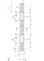
- FIG. 1 is a diagram illustrating a multi-core according to a first embodiment of the present invention.
- 2A to 2C are diagrams illustrating an example of a manufacturing method for an optical fiber ribbon according to the first embodiment of the present invention.
- FIG. 5B is a diagram showing a state following FIG. 5A.
- FIG. 5C is a diagram showing a state following FIG. 5B.
- FIG. 6B is a diagram showing a state following FIG. 6A.
- FIG. 6B is a diagram showing a state following FIG. 6B.
- 4 is a plan view showing an optical fiber ribbon according to a second embodiment of the present invention.
- the optical fiber cable C includes at least one optical fiber ribbon 100 with a connector.
- the optical fiber ribbon 100 with a connector is housed in a tubular outer jacket 200.
- the outer jacket 200 is formed of, for example, resin.
- the outer jacket 200 protects the optical fiber ribbon 100 with a connector.
- the number of optical fiber ribbons 100 with connectors housed in the outer jacket 200 can be changed as appropriate.
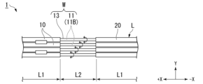
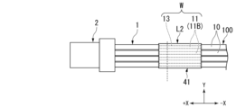
- each connectorized optical fiber ribbon 100 includes an optical fiber ribbon 1 and a connector (ferrule) 2 attached to the end of the optical fiber ribbon 1.
- the connector 2 has a connection end face 2a.
- the connection end face 2a is the surface that is abutted against another connector or the like when the connector 2 is connected to the other connector or the like.
- the optical fiber ribbon 1 comprises a plurality of span multi-core fibers (optical fibers) 10.
- the plurality of span multi-core fibers 10 are arranged side by side in a direction intersecting (e.g., perpendicular to) the longitudinal direction of the span multi-core fibers 10. This gives the optical fiber ribbon 1 a ribbon-like (tape-like) shape.
- the number of span multi-core fibers 10 included in the optical fiber ribbon 1 can be changed as appropriate.
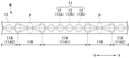
- the spun multicore fiber 10 has a multicore 11, a clad 13, and a coating layer L.
- the multicore 11 has a plurality of cores 12.
- the clad 13 covers the multicore 11 (the plurality of cores 12).
- the cores 12 and the clad 13 are formed of, for example, quartz glass.
- the refractive index of each core 12 is smaller than the refractive index of the clad 13. This allows the spun multicore fiber 10 to confine light inside the core 12.
- the multicore 11 (the plurality of cores 12) and the clad 13 may be collectively referred to as the waveguide section W.
- the coating layer L covers the clad 13 (waveguide section W).
- the coating layer L is provided with a coating section 20 that covers the multi-core 11.
- the coating section 20 is formed, for example, from a UV-curable resin.
- the longitudinal direction of the spun multi-core fiber 10 (the longitudinal direction of the cladding 13) is simply referred to as the longitudinal direction X.
- the longitudinal direction X is also a direction parallel to the central axis O (see also FIG. 3) of each spun multi-core fiber 10.
- a direction intersecting (e.g., perpendicular to) the longitudinal direction X and in which the multiple spun multi-core fibers 10 are arranged is referred to as the cross direction Y.
- a direction intersecting (e.g., perpendicular to) both the longitudinal direction X and the cross direction Y is referred to as the thickness direction Z.
- the thickness direction Z is also the thickness direction of the optical fiber ribbon 1.
- a direction from the optical fiber ribbon 1 toward the connector 2 along the longitudinal direction X is referred to as the front or tip side, and is represented by the +X direction.
- a direction opposite to the +X direction is referred to as the rear or base side, and is represented by the -X direction.
- a cross section perpendicular to the longitudinal direction X is referred to as a transverse cross section.
- a view from the thickness direction Z is referred to as a planar view.
- a direction perpendicular to the central axis O of the spun multi-core fiber 10 is referred to as a radial direction.
- a direction approaching the central axis O along the radial direction is referred to as a radially inner direction, and a direction moving away from the central axis O is referred to as a radially outer direction.
- a direction going around the central axis O is referred to as a circumferential direction.
- the multiple spun multi-core fibers 10 are fixed to each other by multiple fixing parts 30.
- the fixing parts 30 fix the coating layers L between the multiple spun multi-core fibers 10 so that they are aligned in the crossing direction Y.
- each fixing part 30 fixes two adjacent spun multi-core fibers 10 to each other in the crossing direction Y.
- the multiple fixing parts 30 are also arranged intermittently in the longitudinal direction X and the crossing direction Y.
- a UV-curable resin may be used as the fixing parts 30.
- the configuration of the fixing portion 30 can be changed as appropriate as long as it is possible to fix adjacent spun multi-core fibers 10.
- multiple spun multi-core fibers 10 may be covered by a single fixing portion 30.
- the spun multi-core fibers 10 can be fixed to each other with sufficient strength, for example by resin 41 (described later), the optical fiber ribbon 1 does not need to have a fixing portion 30.
- the multiple cores 12 include one central core 12a and multiple (two in the illustrated example) non-central cores 12b.
- the central core 12a is a core 12 that extends linearly in the longitudinal direction X so as to include the central axis O of the spun multicore fiber 10 (see also FIG. 4).
- the non-central cores 12b are cores 12 other than the central core 12a.
- the multi-core 11 (span multi-core fiber 10) has multiple helical portions 11A and multiple non-helical portions 11B.
- the multiple helical portions 11A are arranged at intervals in the longitudinal direction X.
- the multiple non-helical portions 11B are located between the multiple helical portions 11A in the longitudinal direction X.
- the multiple helical portions 11A and the multiple non-helical portions 11B are arranged alternately in the longitudinal direction X.
- the multi-core 11 may have only one helical portion 11A, or may have only one non-helical portion 11B.
- the multiple cores 12 are wound in a helical shape.
- the positions of the multiple cores 12 (non-center cores 12b) in the longitudinal direction X change in a helical shape.
- the term "helical” specifically means a shape in which the position in the circumferential direction changes as the position in the longitudinal direction X changes.
- the multiple helical portions 11A include multiple forward helical portions 11A1 and multiple reverse helical portions 11A2.
- the forward helical portion 11A1 and the reverse helical portion 11A2 have the cores 12 wound in opposite directions.
- each non-helical portion 11B is disposed between the forward helical portion 11A1 and the reverse helical portion 11A2.
- the cores 12 are not wound in a helical shape.
- the positions of the cores 12 in the longitudinal direction X do not change in a helical shape. That is, in the non-helical portion 11B, the circumferential position of each core 12 is approximately constant along the longitudinal direction X.
- the radial position of the core 12 (the distance from the central axis O) changes along the longitudinal direction X.
- the radial position of the core 12 may be approximately constant along the longitudinal direction X.
- each core 12 may extend linearly along the longitudinal direction X.
- the term "approximately constant" also includes cases where the cores 12 can be considered constant if manufacturing errors are removed.
- the multiple cores 12 are rotationally aligned in each of the multiple non-helical portions 11B.
- “the multiple cores 12 (multi-cores 11) are rotationally aligned” means that the circumferential position of each core 12 (the rotation angle of the multi-core 11 around the central axis O) is adjusted within a predetermined range.
- the circumferential positions of the multiple cores 12 (non-central cores 12b) of the multi-core 11 are approximately the same among all span multi-core fibers 10. Note that the term "approximately the same” also includes cases where they can be considered to be the same if manufacturing errors are removed.
- the coating layer L has a plurality of coating regions L1 and a plurality of coating removal regions L2.
- the coating region L1 is a region where the coating portion 20 is provided.
- the coating removal region L2 is a region where the coating portion 20 is not provided. In other words, the coating removal region L2 is a region where the coating portion 20 has been removed.
- the plurality of coating regions L1 and the plurality of coating removal regions L2 are arranged alternately in the longitudinal direction X.
- the coating removal area L2 is provided at a position corresponding to the non-helical portion 11B described above. Specifically, the range in which the coating removal area L2 exists and the range in which the non-helical portion 11B exists overlap in the longitudinal direction X. In other words, in a plan view, the coating removal area L2 and the non-helical portion 11B overlap. For example, the center in the longitudinal direction X of the coating removal area L2 and the center in the longitudinal direction X of the non-helical portion 11B may be at approximately the same position.
- the end closest to the connector 2 is referred to as the front end L2a
- the end farthest from the connector 2 is referred to as the rear end L2b.
- resin (first resin) 41 is provided in the coating removal region L2.
- resin 41 is provided from the front end L2a to the rear end L2b of the coating removal region L2. That is, resin 41 according to this embodiment is provided throughout the entire coating removal region L2.
- resin 41 bonds and fixes cladding 13 (waveguide W) and coating 20.
- Young's modulus of resin 41 is relatively high.
- Young's modulus of resin 41 is preferably 500 MPa or more.
- the region of resin 41 may be expanded to include a portion of coating region L1 in addition to the entire region of coating removal region L2.
- an optical fiber ribbon 1' including a plurality of spun multi-core fibers 10' is prepared.
- the optical fiber ribbon 1' does not have the above-mentioned coating removal region L2.
- the cladding 13 is covered with the coating portion 20 over the entire length in the longitudinal direction X.
- the coating region L1 is provided over the entire length of the cladding 13 (coating layer L) in the longitudinal direction X.
- the coating portion 20 (coating layer L) of the spun multicore fiber 10' is provided with an indicator 21 indicating the position of the non-helical portion 11B.
- the indicator 21 is a mark marked on the coating portion 20.
- the position of the indicator 21 corresponds to the position of the non-helical portion 11B.
- the range in which the indicator 21 exists and the range in which the non-helical portion 11B exists overlap in the longitudinal direction X.
- the indicator 21 and the non-helical portion 11B overlap.
- the center of the indicator 21 in the longitudinal direction X and the center of the non-helical portion 11B in the longitudinal direction X may be substantially in the same position.
- the indicator 21 may be provided at a position in the non-helical portion 11B where the cores 12 are closest to each other (position P shown in FIG. 4).
- the covering portion 20 is removed from the periphery of the display portion 21 (see FIG. 5B).
- the portion from which the covering portion 20 is removed in this process is the covering removal region L2 described above.
- the position of the display portion 21 corresponds to the position of the non-helical portion 11B
- the position of the covering removal region L2 corresponds to the position of the non-helical portion 11B as described above.
- the non-helical portion 11B is rotationally aligned in the coating removal region L2.
- the waveguide portion W is grasped and rotated around the central axis O of the spun multicore fiber 10. This causes the waveguide portion W to rotate relative to the coating portion 20 in the coating removal region L2 and its vicinity.
- the position of each core 12 may be confirmed, for example, by irradiating light from the side of the non-helical portion 11B.
- the optical fiber ribbon 100 is filled into the coating removal area L2 (see FIG. 5C).
- the adhesive force of the resin 41 fixes the waveguide W to the coating 20 while the non-helical portion 11B is rotationally aligned.
- the optical fiber ribbon 1 is cut in the coating removal area L2.
- the resin 41 is removed to expose the waveguide W, and the exposed waveguide W is inserted into the connector 2.
- multicore fibers in which multiple cores are arranged inside one cladding.
- the multicore fiber is generally rotated and aligned.
- the multicores may rotate relative to the coating after the rotation alignment operation, resulting in variation in the rotation angle of the multicore fiber.
- the optical fiber ribbon 1 has a coating removal region L2 where the coating 20 has been removed.
- Resin 41 is provided in the coating removal region L2 to adhesively fix the cladding 13 and the coating 20 together.
- the adhesive strength of the resin 41 suppresses relative rotation of the waveguide W (multi-core 11) with respect to the coating 20.
- the multiple span multi-core fibers 10 are fixed in a tape shape by the fixing portion 30 and the resin 41 with the non-helical portion 11B rotated and aligned.
- the connector 2 can be easily replaced, for example, by the method described below.
- the optical fiber ribbon 1 is first cut in the coating removal region L2.
- the Young's modulus of the resin 41 is relatively low so that the optical fiber ribbon 1 can be easily cut.
- the Young's modulus of the resin 41 is preferably, for example, 1000 MPa or less.
- the Young's modulus of the resin 41 according to this embodiment is, for example, in the range of 500 MPa or more and 1000 MPa or less. Note that in the illustrated example, the optical fiber ribbon 1 is cut in the coating removal region L2 that is closest to the connector 2 among the multiple coating removal regions L2 (see also FIG. 2), but the optical fiber ribbon 1 may be cut in another coating removal region L2.
- the replacement part 100A When replacing the connector 2, a replacement part 100A as shown in FIG. 6B is prepared.
- the replacement part 100A includes a replacement connector 2A and a replacement optical fiber ribbon 1A.
- the configuration of the replacement connector 2A may be the same as that of the connector 2.
- a coating removal region L2 is provided at the rear end of the replacement optical fiber ribbon 1A.
- the coating removal region L2 includes resin 41 and a non-helical portion 11B that has been rotationally aligned in advance.
- the resin 41 is removed from both the coating removal region L2 of the optical fiber ribbon 1 and the coating removal region L2 of the replacement optical fiber ribbon 1A. This exposes the front end of the waveguide section W of the optical fiber ribbon 1 and the rear end of the waveguide section W of the replacement optical fiber ribbon 1A.
- the optical fiber ribbon 1 and the replacement part 100A are connected by fusion splicing the front ends of the multiple waveguide sections W of the optical fiber ribbon 1 and the rear ends of the multiple waveguide sections W of the replacement optical fiber ribbon 1A.
- the non-helical section 11B is rotationally aligned in advance in the coating removal region L2 and the span multicore fibers 10 are fixed to each other in a tape shape, the multiple waveguide sections W can be easily connected together. Note that when performing the fusion splicing, the end of the waveguide section W may be polished as necessary. Finally, the coating removal region L2 is filled with resin 41 again to complete the replacement work of the connector 2.
- the optical fiber ribbon 1 includes a spun multi-core fiber (optical fiber) 10 having a plurality of cores 12 in a clad 13, a helical portion 11A in which the positions of the plurality of cores 12 change helically in the longitudinal direction X of the clad 13, a non-helical portion 11B in which the positions of the plurality of cores 12 do not change helically in the longitudinal direction X, and a coating layer L that covers the clad 13, and a fixing portion 30 that fixes the coating layer L so that the plurality of spun multi-core fibers 10 are aligned in a direction (crossing direction Y) that intersects the longitudinal direction X.
- a spun multi-core fiber (optical fiber) 10 having a plurality of cores 12 in a clad 13, a helical portion 11A in which the positions of the plurality of cores 12 change helically in the longitudinal direction X of the clad 13, a non-helical portion 11B in which the positions of the plurality
- the coating layer L has a coating region L1 in which a coating portion 20 that covers the clad 13 is provided, and a coating removal region L2 in which the coating portion 20 is removed and is provided at a position corresponding to the non-helical portion 11B.
- the coating removal region L2 is provided with a resin 41 (first resin) that adhesively fixes the clad 13 and the coating portion 20.
- the adhesive strength of the resin 41 suppresses the relative rotation of the cladding 13 and the multi-cores 11 with respect to the coating portion 20. Furthermore, since the multiple span multi-core fibers 10 are fixed in a tape shape by the fixing portion 30 and the resin 41, the connector 2 can be easily attached to the optical fiber ribbon 1.
- the spun multicore fiber 10 also has a plurality of helical portions 11A spaced apart in the longitudinal direction X, and a plurality of non-helical portions 11B located between the plurality of helical portions 11A in the longitudinal direction X. This configuration allows the worker to arbitrarily select the location where the connector 2 is to be attached from among the plurality of non-helical portions 11B.
- the multiple cores 12 are rotationally aligned in the non-helical portion 11B. If the helical portion 11A were rotationally aligned instead of the non-helical portion 11B, and the connector 2 were attached to the helical portion 11A, the position of the core 12 exposed at the tip of the waveguide portion W would change in the circumferential direction depending on the amount of polishing of the waveguide portion W. By performing rotational alignment in the non-helical portion 11B instead of the helical portion 11A, it is possible to suppress misalignment of the core 12 in the circumferential direction regardless of the amount of polishing of the waveguide portion W. This makes it easier to attach the connector 2 to the optical fiber ribbon 1.
- the resin 41 is provided over the entire coating removal region L2. With this configuration, the cladding 13 (waveguide section W) and the coating section 20 can be fixed more firmly than if the resin 41 were provided only on the ends L2a and L2b of the coating removal region L2. The resin 41 can also protect the cladding 13 (waveguide section W).
- the optical fiber cable C includes an optical fiber ribbon 100 with a connector, which includes the optical fiber ribbon 1 described above and a connector 2 attached to the end of the optical fiber ribbon 1.
- This configuration suppresses the relative rotation of the multi-cores 11 with respect to the coating 20 in each optical fiber ribbon 1, realizing an optical fiber cable C to which the connector 2 can be easily attached.
- the spun multicore fiber 10' includes a multicore 11 having a cladding 13, a plurality of cores 12 arranged in the cladding 13, a helical portion 11A in which the positions of the plurality of cores 12 change helically in the longitudinal direction X of the cladding 13, and a non-helical portion 11B in which the positions of the plurality of cores 12 do not change helically in the longitudinal direction X, and a coating portion 20 (coating layer L) that covers the cladding 13, and the coating portion 20 (coating layer L) is provided with an indicator portion 21 that indicates the position of the non-helical portion 11B.
- the optical fiber ribbon 1, the optical fiber ribbon 100 with connector, and the optical fiber cable C described above can be easily manufactured.
- both resins 41A and 42A cover the cladding 13.
- the first resin 41A is provided at least in the rear end portion L2b of the coating removal region L2.
- the second resin 42A is disposed at a position different from the first resin 41A in the longitudinal direction X.
- the second resin 42A is provided over all parts of the coating removal region L2 except for the portion (rear end portion L2b) where the first resin 41A is provided.
- the Young's modulus of the second resin 42A is lower than that of the first resin 41A.
- the first resin 41A bonds and fixes the cladding 13 (waveguide section W) and the covering section 20. From the viewpoint of fixing strength, it is preferable that the Young's modulus of the first resin 41A is relatively high, like the resin 41 in the first embodiment. It is preferable that the Young's modulus of the first resin 41A is, for example, 500 MPa or more.
- a second resin 42A having a lower Young's modulus than the first resin 41A is provided in the coating removal area L2. Therefore, even if the Young's modulus of the first resin 41A is extremely high, the optical fiber ribbon 3 can be cut in the portion where the second resin 42A is provided. Therefore, the Young's modulus of the first resin 41A in this embodiment may be, for example, 1000 MPa or more. And, it is preferable that the Young's modulus of the second resin 42A is somewhat low. It is preferable that the Young's modulus of the second resin 42A is, for example, 10 MPa or more and 100 MPa or less.
- the second resin 42A is provided in the coating removal area L2, which is arranged in a position different from the first resin 41A in the longitudinal direction X and covers the cladding 13, and the Young's modulus of the second resin 42A is lower than the Young's modulus of the first resin 41A.
- the first resin 41A is provided at least at the end (rear end L2b) farthest from the connector 2 out of both ends in the longitudinal direction X of the coating removal area L2. With this configuration, the first resin 41A can continue to adhere and fix the waveguide section W (clad 13) to the coating section 20 even after the optical fiber ribbon 3 is cut, for example, as shown in FIG. 6A.
- the multiple cores 12 are rotationally aligned in each of the multiple non-helical portions 11B, but there may be a non-helical portion 11B in which the multiple cores 12 are not rotationally aligned.
- the multiple cores 12 rotationally aligned in at least one non-helical portion 11B and providing a coating removal region L2 at a position corresponding to this non-helical portion 11B, it is possible to achieve the same effect as in the above embodiment.
- the resin 41, 41A, or 42A is provided over the entire coating removal region L2, but the resin 41, 41A, or 42A may not be provided in a portion of the coating removal region L2, and the clad 13 (waveguide W) may be exposed. Even in this case, the resin 41, 41A that bonds and fixes the clad 13 (waveguide W) to the coating 20 is provided in the coating removal region L2, so that the relative rotation of the multi-core 11 (waveguide W) can be suppressed. In this case, it is preferable that the resin 41, 41A is provided at least in the rear end portion L2b of the coating removal region L2. This is because the resin 41, 41A can continue to bond and fix the waveguide W (clad 13) to the coating 20 even after the optical fiber ribbons 1 and 3 are cut as shown in FIG. 6A.
- C...optical fiber cable 100...optical fiber ribbon with connector 1, 3...optical fiber ribbon 2...connector 10, 10'...span multicore fiber (optical fiber) 11...multicore 11A...spiral portion 11B...non-spiral portion 12...core 13...cladding 20...coating portion 21...display portion 41, 41A...first resin 42A...second resin L...coating layer L1...coating area L2...coating removal area L2a...front end L2b...rear end X...longitudinal direction Y...cross direction
Landscapes
- Physics & Mathematics (AREA)
- General Physics & Mathematics (AREA)
- Optics & Photonics (AREA)
- Engineering & Computer Science (AREA)
- Manufacturing & Machinery (AREA)
- Mechanical Coupling Of Light Guides (AREA)
Priority Applications (3)
| Application Number | Priority Date | Filing Date | Title |
|---|---|---|---|
| JP2024565601A JPWO2024134992A1 (https=) | 2022-12-22 | 2023-08-28 | |
| CN202380085617.5A CN120359443A (zh) | 2022-12-22 | 2023-08-28 | 光纤带、带连接器的光纤带、光纤线缆以及光纤 |
| EP23906369.6A EP4641276A1 (en) | 2022-12-22 | 2023-08-28 | Optical fiber ribbon, connector-equipped optical fiber ribbon, optical fiber cable and optical fiber |
Applications Claiming Priority (2)
| Application Number | Priority Date | Filing Date | Title |
|---|---|---|---|
| JP2022-205304 | 2022-12-22 | ||
| JP2022205304 | 2022-12-22 |
Publications (1)
| Publication Number | Publication Date |
|---|---|
| WO2024134992A1 true WO2024134992A1 (ja) | 2024-06-27 |
Family
ID=91588021
Family Applications (1)
| Application Number | Title | Priority Date | Filing Date |
|---|---|---|---|
| PCT/JP2023/030944 Ceased WO2024134992A1 (ja) | 2022-12-22 | 2023-08-28 | 光ファイバリボン、コネクタ付き光ファイバリボン、光ファイバケーブルおよび光ファイバ |
Country Status (4)
| Country | Link |
|---|---|
| EP (1) | EP4641276A1 (https=) |
| JP (1) | JPWO2024134992A1 (https=) |
| CN (1) | CN120359443A (https=) |
| WO (1) | WO2024134992A1 (https=) |
Cited By (1)
| Publication number | Priority date | Publication date | Assignee | Title |
|---|---|---|---|---|
| WO2026074849A1 (ja) * | 2024-10-03 | 2026-04-09 | 株式会社フジクラ | 光ファイバケーブル |
Citations (7)
| Publication number | Priority date | Publication date | Assignee | Title |
|---|---|---|---|---|
| WO2002093219A1 (en) * | 2001-05-10 | 2002-11-21 | 3M Innovative Properties Company | Optical fiber recoat |
| JP2015145989A (ja) * | 2014-02-04 | 2015-08-13 | 住友電気工業株式会社 | マルチコアファイバの調芯方法、コネクタの製造方法、及びリボンファイバの製造方法 |
| WO2015126470A2 (en) * | 2013-11-22 | 2015-08-27 | Corning Optical Communications LLC | Multicore optical fibers and methods of manufacturing the same |
| WO2015137236A1 (ja) * | 2014-03-10 | 2015-09-17 | 住友電気工業株式会社 | 光モジュール製造方法 |
| WO2016163190A1 (ja) * | 2015-04-07 | 2016-10-13 | 株式会社フジクラ | ルースチューブ、ルースチューブ型光ファイバケーブル、ルースチューブの光ファイバテープの単心分離方法、ルースチューブの製造方法、及び、複数の光ファイバの集線方法 |
| JP2019053244A (ja) * | 2017-09-19 | 2019-04-04 | 住友電気工業株式会社 | 光ファイバ接続構造 |
| JP2022075219A (ja) | 2020-11-06 | 2022-05-18 | 株式会社フジクラ | コネクタ付きマルチコアファイバ |
-
2023
- 2023-08-28 WO PCT/JP2023/030944 patent/WO2024134992A1/ja not_active Ceased
- 2023-08-28 CN CN202380085617.5A patent/CN120359443A/zh active Pending
- 2023-08-28 EP EP23906369.6A patent/EP4641276A1/en active Pending
- 2023-08-28 JP JP2024565601A patent/JPWO2024134992A1/ja active Pending
Patent Citations (7)
| Publication number | Priority date | Publication date | Assignee | Title |
|---|---|---|---|---|
| WO2002093219A1 (en) * | 2001-05-10 | 2002-11-21 | 3M Innovative Properties Company | Optical fiber recoat |
| WO2015126470A2 (en) * | 2013-11-22 | 2015-08-27 | Corning Optical Communications LLC | Multicore optical fibers and methods of manufacturing the same |
| JP2015145989A (ja) * | 2014-02-04 | 2015-08-13 | 住友電気工業株式会社 | マルチコアファイバの調芯方法、コネクタの製造方法、及びリボンファイバの製造方法 |
| WO2015137236A1 (ja) * | 2014-03-10 | 2015-09-17 | 住友電気工業株式会社 | 光モジュール製造方法 |
| WO2016163190A1 (ja) * | 2015-04-07 | 2016-10-13 | 株式会社フジクラ | ルースチューブ、ルースチューブ型光ファイバケーブル、ルースチューブの光ファイバテープの単心分離方法、ルースチューブの製造方法、及び、複数の光ファイバの集線方法 |
| JP2019053244A (ja) * | 2017-09-19 | 2019-04-04 | 住友電気工業株式会社 | 光ファイバ接続構造 |
| JP2022075219A (ja) | 2020-11-06 | 2022-05-18 | 株式会社フジクラ | コネクタ付きマルチコアファイバ |
Non-Patent Citations (1)
| Title |
|---|
| See also references of EP4641276A1 |
Cited By (1)
| Publication number | Priority date | Publication date | Assignee | Title |
|---|---|---|---|---|
| WO2026074849A1 (ja) * | 2024-10-03 | 2026-04-09 | 株式会社フジクラ | 光ファイバケーブル |
Also Published As
| Publication number | Publication date |
|---|---|
| CN120359443A (zh) | 2025-07-22 |
| JPWO2024134992A1 (https=) | 2024-06-27 |
| EP4641276A1 (en) | 2025-10-29 |
Similar Documents
| Publication | Publication Date | Title |
|---|---|---|
| WO2018105424A1 (ja) | 間欠連結型光ファイバテープ心線、その製造方法、光ファイバケーブルおよび光ファイバコード | |
| CN104081234B (zh) | 多芯光纤带 | |
| JP5691236B2 (ja) | マルチコア光ファイバ及びマルチコア光ファイバの単芯分離方法 | |
| US12298571B2 (en) | Optical fiber bundle structure, optical connection structure, and method of manufacturing optical fiber bundle | |
| WO2024134992A1 (ja) | 光ファイバリボン、コネクタ付き光ファイバリボン、光ファイバケーブルおよび光ファイバ | |
| JP7613462B2 (ja) | 光ファイバ接続部品及び光ファイバ接続部品の製造方法 | |
| EP3943992B1 (en) | Intermittent connection-type optical fiber tape core, optical fiber cable and connector-equipped optical fiber cord | |
| WO2021131977A1 (ja) | マルチコアファイバ、光ファイバケーブル、及び光コネクタ | |
| JP3773584B2 (ja) | 光ファイバーテープケーブル | |
| WO2023058566A1 (ja) | 光ファイバテープ心線 | |
| US20240255709A1 (en) | Optical fiber bundle, optical connection structure, and method for manufacturing optical fiber bundle | |
| JP5261265B2 (ja) | バンドルファイバ | |
| JP2003329887A (ja) | 多心光ファイバテープ心線付き光コネクタ及び多心光ファイバコード付き光コネクタ | |
| US12481106B2 (en) | Optical-fiber bundle structure, optical connection structure, and method of manufacturing optical-fiber bundle structure | |
| JP7778248B2 (ja) | マルチコア光ファイバの調心装置、マルチコア光ファイバリボンの製造装置、マルチコア光ファイバユニットの製造装置、マルチコア光ファイバの調心方法、マルチコア光ファイバリボンの製造方法、マルチコア光ファイバユニットの製造方法、マルチコア光ファイバリボンの検査装置、及びマルチコア光ファイバリボンの検査方法 | |
| WO2022138763A1 (ja) | 光ファイバ接続部品の製造方法 | |
| JP2021026167A (ja) | 光コネクタ | |
| JPWO2024134992A5 (https=) | ||
| WO2026074849A1 (ja) | 光ファイバケーブル | |
| KR0172629B1 (ko) | 다심형 광파이버커플러의 보강구조 | |
| JP7400739B2 (ja) | 光コネクタの製造方法 | |
| JP2023082856A (ja) | 光ファイババンドル構造、光接続構造体、及び、光ファイババンドル構造の製造方法 | |
| US20240255705A1 (en) | Method for manufacturing optical fiber bundle, optical fiber bundle, optical connection structure, and determination method | |
| JP7745739B2 (ja) | 光ファイバ、光デバイス及び光デバイスの製造方法 | |
| CN120476331A (zh) | 多芯光纤 |
Legal Events
| Date | Code | Title | Description |
|---|---|---|---|
| 121 | Ep: the epo has been informed by wipo that ep was designated in this application |
Ref document number: 23906369 Country of ref document: EP Kind code of ref document: A1 |
|
| WWE | Wipo information: entry into national phase |
Ref document number: 202380085617.5 Country of ref document: CN |
|
| WWE | Wipo information: entry into national phase |
Ref document number: 2024565601 Country of ref document: JP |
|
| WWE | Wipo information: entry into national phase |
Ref document number: 2023906369 Country of ref document: EP |
|
| WWP | Wipo information: published in national office |
Ref document number: 202380085617.5 Country of ref document: CN |
|
| NENP | Non-entry into the national phase |
Ref country code: DE |
|
| ENP | Entry into the national phase |
Ref document number: 2023906369 Country of ref document: EP Effective date: 20250722 |
|
| ENP | Entry into the national phase |
Ref document number: 2023906369 Country of ref document: EP Effective date: 20250722 |
|
| ENP | Entry into the national phase |
Ref document number: 2023906369 Country of ref document: EP Effective date: 20250722 |
|
| WWP | Wipo information: published in national office |
Ref document number: 2023906369 Country of ref document: EP |