WO2024127916A1 - 車両用灯具制御装置 - Google Patents
車両用灯具制御装置 Download PDFInfo
- Publication number
- WO2024127916A1 WO2024127916A1 PCT/JP2023/041576 JP2023041576W WO2024127916A1 WO 2024127916 A1 WO2024127916 A1 WO 2024127916A1 JP 2023041576 W JP2023041576 W JP 2023041576W WO 2024127916 A1 WO2024127916 A1 WO 2024127916A1
- Authority
- WO
- WIPO (PCT)
- Prior art keywords
- circuit
- control device
- constant current
- value
- current source
- Prior art date
- Legal status (The legal status is an assumption and is not a legal conclusion. Google has not performed a legal analysis and makes no representation as to the accuracy of the status listed.)
- Ceased
Links
Images









Classifications
-
- H—ELECTRICITY
- H05—ELECTRIC TECHNIQUES NOT OTHERWISE PROVIDED FOR
- H05B—ELECTRIC HEATING; ELECTRIC LIGHT SOURCES NOT OTHERWISE PROVIDED FOR; CIRCUIT ARRANGEMENTS FOR ELECTRIC LIGHT SOURCES, IN GENERAL
- H05B45/00—Circuit arrangements for operating light-emitting diodes [LED]
- H05B45/30—Driver circuits
- H05B45/345—Current stabilisation; Maintaining constant current
-
- H—ELECTRICITY
- H05—ELECTRIC TECHNIQUES NOT OTHERWISE PROVIDED FOR
- H05B—ELECTRIC HEATING; ELECTRIC LIGHT SOURCES NOT OTHERWISE PROVIDED FOR; CIRCUIT ARRANGEMENTS FOR ELECTRIC LIGHT SOURCES, IN GENERAL
- H05B45/00—Circuit arrangements for operating light-emitting diodes [LED]
- H05B45/30—Driver circuits
- H05B45/395—Linear regulators
-
- H—ELECTRICITY
- H05—ELECTRIC TECHNIQUES NOT OTHERWISE PROVIDED FOR
- H05B—ELECTRIC HEATING; ELECTRIC LIGHT SOURCES NOT OTHERWISE PROVIDED FOR; CIRCUIT ARRANGEMENTS FOR ELECTRIC LIGHT SOURCES, IN GENERAL
- H05B45/00—Circuit arrangements for operating light-emitting diodes [LED]
- H05B45/50—Circuit arrangements for operating light-emitting diodes [LED] responsive to malfunctions or undesirable behaviour of LEDs; responsive to LED life; Protective circuits
- H05B45/54—Circuit arrangements for operating light-emitting diodes [LED] responsive to malfunctions or undesirable behaviour of LEDs; responsive to LED life; Protective circuits in a series array of LEDs
-
- H—ELECTRICITY
- H05—ELECTRIC TECHNIQUES NOT OTHERWISE PROVIDED FOR
- H05B—ELECTRIC HEATING; ELECTRIC LIGHT SOURCES NOT OTHERWISE PROVIDED FOR; CIRCUIT ARRANGEMENTS FOR ELECTRIC LIGHT SOURCES, IN GENERAL
- H05B47/00—Circuit arrangements for operating light sources in general, i.e. where the type of light source is not relevant
- H05B47/20—Responsive to malfunctions or to light source life; for protection
- H05B47/21—Responsive to malfunctions or to light source life; for protection of two or more light sources connected in parallel
-
- H—ELECTRICITY
- H05—ELECTRIC TECHNIQUES NOT OTHERWISE PROVIDED FOR
- H05B—ELECTRIC HEATING; ELECTRIC LIGHT SOURCES NOT OTHERWISE PROVIDED FOR; CIRCUIT ARRANGEMENTS FOR ELECTRIC LIGHT SOURCES, IN GENERAL
- H05B47/00—Circuit arrangements for operating light sources in general, i.e. where the type of light source is not relevant
- H05B47/20—Responsive to malfunctions or to light source life; for protection
- H05B47/23—Responsive to malfunctions or to light source life; for protection of two or more light sources connected in series
Definitions
- the present invention relates to a vehicle lighting control device.
- vehicle lighting fixtures In recent years, there has been a growing market need for vehicle-mounted headlamps, rear lamps, and other lighting fixtures (hereinafter referred to as “vehicle lighting fixtures") to display a variety of expressions, such as animations, and to communicate information (communicate) with external objects and people (following vehicles, oncoming vehicles, drivers of other vehicles, pedestrians, etc.) in a highly detailed manner.
- vehicle lighting fixtures As the expressions required of vehicle lighting fixtures become more diverse and complex, efforts are being made to standardize and share the mechanisms for controlling lighting, and to streamline software management systems using mechanisms such as OTA (Over The Air).
- OTA Over The Air
- Patent Document 1 describes a vehicle lighting device configured for the purpose of controlling multiple lamps in an integrated manner.
- Patent Document 2 describes a vehicle control device (electronic control unit) configured to update software stored in an ECU (Electronic Control Unit) mounted on a vehicle via OTA.
- ECU Electronic Control Unit
- Vk the value of the voltage (hereinafter referred to as "Vk") applied to the constant current source may change. This may result in an increase in power consumption or heat generation due to the voltage value (Vk) applied to the constant current source becoming excessive, or the value of the voltage (Vk) applied to the constant current source may be below (too small) the value necessary for the constant current source to operate properly, which may lead to the light-emitting element not lighting up (see, for example, Patent Document 3). Therefore, some kind of measures must be taken to address these issues when realizing a variety of expressions using vehicle lighting fixtures and improving the efficiency of the lighting control mechanism.
- changes in the current flowing through the light-emitting element can be a factor in changing the temperature of the light-emitting element.
- the temperature of the light-emitting element also changes depending on the environment in which the vehicle is placed and the self-heating of the light-emitting element.
- Vk the value of the voltage (hereinafter referred to as "Vk") applied to the constant current source changes due to the temperature characteristics of the light-emitting element
- the value of the voltage (Vk) applied to the constant current source may become excessive, which may increase power consumption and heat generation, or the value of the voltage (Vk) applied to the constant current source may fall below (become too small) the value necessary for the constant current source to operate properly, which may lead to the light-emitting element not lighting up (see, for example, Patent Document 3). Therefore, when controlling the lighting of the light-emitting element that constitutes a vehicle lamp, some kind of measure must be taken to address these issues.
- the present invention was made in light of this background, and aims to provide a vehicle lighting control device that can solve problems that arise when controlling the lighting of light-emitting elements that make up a vehicle lamp.
- one aspect of the present invention is a vehicle lamp control device that includes a first constant current source that supplies a constant current to a light-emitting element used in a vehicle lamp, a resistor circuit connected in series to the light-emitting element and the first constant current source, a current value control circuit that controls the value of the current of the first constant current source in response to a lighting state instruction that indicates the lighting state of the light-emitting element, and a resistance value control circuit that changes the resistance value of the resistor circuit so that changes in the value of the voltage applied to the first constant current source are suppressed when the value of the current supplied to the light-emitting element changes.
- a vehicle lamp control device comprising: a first constant current source that supplies a constant current to a light-emitting element used in a vehicle lamp; a resistor circuit connected in series to the light-emitting element and the first constant current source; a current value control circuit that controls the value of the current of the first constant current source; and a resistance value control circuit that changes the resistance value of the resistor circuit so that changes in the value of the voltage applied to the first constant current source are suppressed when the temperature around the light-emitting element changes.
- the present invention can solve problems that arise when controlling the lighting of light-emitting elements that make up vehicle lamps.
- FIG. 1 is a diagram showing a schematic configuration of an electronic control system mounted on a vehicle
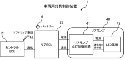
- FIG. 2 is a diagram illustrating a configuration of a vehicle lighting control device.
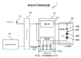
- FIG. 2 is a diagram showing the configuration of a rear lamp lighting control circuit and an LED board.
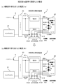
- 1A and 1B are diagrams for explaining problems in lighting control of an LED driven by a constant current.
- 1A and 1B are diagrams for explaining problems in lighting control of an LED driven by a constant current.
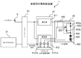
- 1 is a diagram illustrating an example of a vehicle lighting control device according to an embodiment of the present invention
- 1 is a diagram illustrating an example of a vehicle lighting control device according to an embodiment of the present invention
- 1 is a diagram illustrating an example of a vehicle lighting control device according to an embodiment of the present invention
- 1 is a diagram illustrating an example of a vehicle lighting control device according to an embodiment of the present invention
- 1 is a diagram illustrating an example of a vehicle lighting control device according to an embodiment of the present invention
- 1 is a diagram illustrating an example of a vehicle lighting control device according to an embodiment of the present invention
- 1 is a diagram illustrating an example of a vehicle lighting control device according to an embodiment of the present invention
- 1 is a diagram illustrating an example of a vehicle lighting control device according to an embodiment of the present invention
- 1 is a diagram illustrating an example of a vehicle lighting control device according to an embodiment of the present invention
- 1 is a diagram illustrating an example of a vehicle lighting control device according to an embodiment
- 1 is a diagram illustrating an example of a vehicle lighting control device according to an embodiment of the present invention
- 1 is a diagram illustrating an example of a vehicle lighting control device according to an embodiment of the present invention
- 1 is a diagram illustrating an example of a vehicle lighting control device according to an embodiment of the present invention
- 1 is a diagram illustrating an example of a vehicle lighting control device according to an embodiment of the present invention
- 1 is a diagram illustrating an example of a vehicle lighting control device according to an embodiment of the present invention
- 1 is a diagram illustrating an example of a vehicle lighting control device according to an embodiment of the present invention
- 1 is a diagram illustrating an example of a vehicle lighting control device according to an embodiment of the present invention
- 1 is a diagram illustrating an example of a vehicle lighting control device according to an embodiment of the present invention
- 1 is a diagram illustrating an example of a vehicle lighting control device according to an embodiment of the present invention
- 1 is a diagram illustrating an example of a vehicle lighting control device according to an embodiment
- FIG. 1 shows a schematic configuration of an electronic control system 50 mounted on a vehicle 2 as one embodiment of the present invention.
- the illustrated electronic control system 50 includes various ECUs (Electronic Control Units) (such as powertrain ECUs, chassis ECUs, body ECUs, multimedia ECUs, and ADAS (Advanced Driver Assistance Systems) ECUs) that control various parts of the vehicle 2.
- Each ECU includes a processor (such as a CPU (Central Processing Unit) or MPU (Micro Processing Unit)), a storage device (such as memory, SSD, hard disk, portable recording medium, etc.), and a communication device (such as a CAN transceiver), and functions as an information processing device (computer).
- a processor such as a CPU (Central Processing Unit) or MPU (Micro Processing Unit)
- storage device such as memory, SSD, hard disk, portable recording medium, etc.
- a communication device such as a CAN transceiver
- the electronic control system 50 includes a central ECU 21 (first information processing device), a front ECU 22 (second information processing device), and a rear ECU 23 (second information processing device).
- the electronic control system 50 controls the lighting fixtures of the vehicle 2, such as the headlamps 30 and rear lamps 40 (hereinafter referred to as "vehicle lighting fixtures").
- the central ECU 21 is connected to the front ECU 22 and the rear ECU 23 so as to be able to communicate with them, and performs overall control of the front ECU 22 and the rear ECU 23.
- the central ECU 21 operates, for example, as a master device, and the front ECU 22 and the rear ECU 23 operate, for example, as slave devices.
- the front ECU 22 is connected to be able to communicate with the headlamps 30.
- the rear ECU 23 is connected to be able to communicate with the rear lamps 40.
- the headlamps 30 include elements 3 such as, for example, a headlamp, a small lamp, a fog lamp, a DRL (Daytime Running Lamp), a CLL (Clearance Lamp), a Lo/Hi beam control mechanism, an ADB (Adaptive Driving Beam), and an auto-leveling system.
- the rear lamps 40 include elements 4 such as, for example, a turn signal lamp, a tail lamp, a stop lamp, and a back lamp.
- the central ECU 21 transmits lighting method (lighting mode) instruction information (hereinafter referred to as "lighting method instruction”) to the front ECU 22 and rear ECU 23.
- the central ECU 21 also acquires operation information from the front ECU 22 and rear ECU 23, and provides the acquired operation information to the outside of the vehicle 2.
- the central ECU 21 also communicates (wirelessly or wired (e.g., OTA (Over The Air) communication)) with devices external to the vehicle 2 (e.g., the operator terminal 5). By communicating with external devices, the central ECU 21 obtains update information (including update differences) for software (including firmware) stored (memorized) in the front ECU 22 and rear ECU 23.
- the above software includes, for example, software for realizing a variety of expressions such as animation displays using vehicle lamps (e.g., execution code for a program that generates lighting state instructions, described below).
- Communication methods used for communication between the central ECU 21, rear ECU 23, and rear lamp 40 include CAN (Controller Area Network), CAN FD (CAN Flexible Data rate), LIN (Local Interconnect Network), FlexRay (registered trademark), Ethernet (registered trademark), various serial communication methods, etc., but are not necessarily limited to these.
- CAN Controller Area Network
- CAN FD CAN Flexible Data rate
- LIN Local Interconnect Network
- FlexRay registered trademark
- Ethernet registered trademark
- various serial communication methods etc., but are not necessarily limited to these.
- the mainstream mechanism for controlling the lighting of the light-emitting elements that constitute the light source of a vehicle lamp is one in which an overall ECU such as the central ECU 21 sends control instructions individually to the control devices (microcomputers, etc.) provided in each vehicle lamp, and each control device controls a driver circuit (driver IC, etc.) to control the lighting of the light-emitting elements.
- an overall ECU such as the central ECU 21 sends control instructions individually to the control devices (microcomputers, etc.) provided in each vehicle lamp, and each control device controls a driver circuit (driver IC, etc.) to control the lighting of the light-emitting elements.
- the lighting control of the light-emitting elements by the front ECU 22 and rear ECU 23 is mainly performed by software, so there is no need to provide specialized hardware for specific functions (turn signal display, tail display, stop display, reverse display, etc.) in the vehicle lamp, which simplifies the configuration, improves productivity, and reduces the maintenance burden.
- the software for implementing the functions of the front ECU 22 and rear ECU 23 can be updated at any time, and the lighting method (lighting state) of the vehicle lamps can be easily and quickly changed without changing the hardware. This makes it possible to flexibly and quickly respond to various needs for lighting methods of vehicle lamps, such as animation displays.
- FIG. 2 is a block diagram illustrating the configuration of the electronic control system 50 shown in FIG. 1, focusing on the periphery of the rear ECU 23 (hereinafter referred to as the "vehicle lighting control device 1"). Note that the figure illustrates an example of a configuration in which the rear ECU 23 controls the illumination of the rear lamp 40, which is an element 4 provided on the rear side of the vehicle 2.
- the rear lamp 40 includes a rear lamp lighting control circuit 41 and an LED board 42.
- the rear lamp lighting control circuit 41 is connected to the rear ECU 23 so as to be able to communicate with it.
- the rear lamp lighting control circuit 41 and the LED board 42 are also connected by a communication line (CAN, LIN, etc.) or a signal line (direct line (direct wiring)).
- the LED board 42 is mounted with one or more light-emitting elements that constitute the light source of the vehicle lamp.
- the light-emitting element is an LED (Light-Emitting Diode), but the light-emitting element may be another type of light-emitting element (for example, a laser diode, an organic EL (OEL: Organic Electro-Luminescence), etc.) as long as lighting control is performed based on constant current drive.
- LED Light-Emitting Diode
- OEL Organic Electro-Luminescence
- the rear ECU 23, the rear lamp lighting control circuit 41, and the LED board 42 are supplied with power from a battery 6 (power storage device) mounted on the vehicle 2.
- the rear lamp lighting control circuit 41 and the LED board 42 are housed, for example, in a housing (case) of the rear lamp 40 provided on the vehicle 2.
- the rear ECU 23 generates, for example, a lighting state instruction (hereinafter referred to as a "lighting state instruction") according to the lighting method instruction sent from the central ECU 21, and sends it to the rear lamp lighting control circuit 41.
- the rear lamp lighting control circuit 41 controls the lighting of the LEDs mounted on the LED board 42 according to the lighting state instruction sent from the rear ECU 23.
- the lighting state instruction includes information (parameters) that specify the lighting state of the LEDs, such as the value of the current flowing through the LEDs, the timing at which the LEDs are turned on, and the speed at which the brightness of the LEDs is changed (for example, the change over time in the duty ratio when PWM control is performed).
- the voltage source 411 is a device that generates a DC voltage of a predetermined magnitude based on the power supplied from the battery 6, and is configured, for example, using a DC/DC converter (a step-down converter, a step-up converter, a step-up/step-down converter, etc.).
- a DC/DC converter a step-down converter, a step-up converter, a step-up/step-down converter, etc.
- the current source 412 is configured using, for example, an integrated circuit such as a sink driver IC (hereinafter also referred to as a "driver IC").
- the current source 412 includes a plurality of constant current sources 4121 that can individually (independently) control the current (constant current) in response to a lighting state instruction.
- the LED board 42 is provided with one or more LED strings 400.
- Each LED string 400 includes one or more LEDs 405 connected in series.
- a DC voltage of a predetermined magnitude is applied to the LED string 400 from a voltage source 411.
- Each LED string 400 is connected to one of a plurality of constant current sources 4121 provided in a current source 412.
- the LED string 400 includes one or more resistive elements 422 for adjusting the voltage applied to the constant current source 4121.
- the figure illustrates an example of an LED string 400 in which one resistive element 422 and two LEDs 405 are connected in series.
- the brightness (luminance) of the LEDs 405 in the LED row 400 is switched from a brightly lit state to a dimly lit state in response to a lighting state instruction sent from the rear ECU 23.
- An example of a case where such a switching is performed is when the LEDs 405 that have been lit brightly as stop lamps are to be lit dimly as tail lamps.
- the value of the current flowing through the LEDs 405 when they are lit brightly is Ia
- the value of the current flowing through the LEDs 405 when they are lit dimly is Ib ( ⁇ Ia).
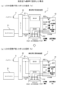
- the resistance value of the resistive element 422 is designed based on Ia, that is, the resistance value of the resistive element 422 is designed so that the voltage value (Vk) applied to the constant current source 4121 is appropriate when a current of Ia flows through the LED string 400.
- the voltage value (Vk) applied to the constant current source 4121 is appropriate when a current of Ia flows through the LED string 400.
- the resistance value of the resistor element 422 is designed based on Ib, that is, the resistance value of the resistor element 422 is designed so that the voltage applied to the constant current source 4121 is appropriate when a current of Ib flows through the LED 405.
- the LED 405 is dimly lit, that is, when the value of the current flowing through the LED 405 is Ib, the voltage drop in the resistor element 422 is appropriate, and the voltage applied to the constant current source 4121 is also appropriate.
- FIG. 4B(a) when the LED 405 is dimly lit, that is, when the value of the current flowing through the LED 405 is Ib, the voltage drop in the resistor element 422 is appropriate, and the voltage applied to the constant current source 4121 is also appropriate.
- the lighting state of the LED 405 will change in response to the lighting state instruction sent from the rear ECU 23, which may lead to an increase in power consumption and heat generation in the constant current source 4121, or the LED 405 not lighting up.
- resistor circuit 420 a resistor circuit capable of changing the resistance value in the LED string 400.
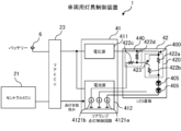
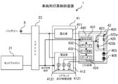
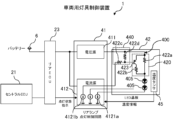
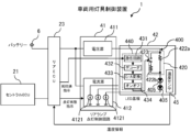
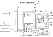
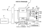
- FIG. 5A shows an example of the configuration of the vehicle lamp control device 1 of this embodiment.
- a resistance circuit 420 is provided in series with the LEDs 405 that make up the LED string 400, and a circuit that controls the resistance value of the resistance circuit 420 (hereinafter referred to as the "resistance control circuit 440").
- the resistance circuit 420 includes a resistance element 422a, a resistance element 422b that is connected in parallel with the resistance element 422a, and a switch 423 that is connected in series with the resistance element 422b and turns on and off the connection to the LED 405.
- the specific configuration of the resistance control circuit 440 will be described later.
- the on/off control of the switch 423 is performed by changing the current value of another constant current source 4121 (hereinafter also referred to as the "second constant current source 4121b"), which is different from the constant current source 4121 (hereinafter also referred to as the "first constant current source 4121a”) that supplies current to the LED string 400, among the multiple constant current sources 4121 included in the current source 412.
- second constant current source 4121b another constant current source 4121
- first constant current source 4121a which supplies current to the LED string 400
- the current source 412 controls the current value of the second constant current source 4121b in response to a lighting state instruction from the rear ECU 23, thereby controlling the on/off of the switch 423 and switching the resistance value of the resistor circuit 420.
- the current source 412 changes the current value of the second constant current source 4121b to turn off the switch 423 and increase the resistance value of the resistance circuit 420 (increase the voltage drop in the resistance circuit 420), thereby preventing an increase in the voltage applied to the first constant current source 4121a.
- the current source 412 changes the current value of the second constant current source 4121b to turn on the switch 423 and reduce the resistance value of the resistance circuit 420 (reducing the voltage drop in the resistance circuit 420), thereby preventing a drop in the voltage applied to the first constant current source 4121a.
- the resistance value of the resistor circuit 420 is changed so that the change in the value of the voltage applied to the first constant current source 4121a caused by the change in the value of the current supplied to the LED 405 in response to the lighting state instruction from the rear ECU 23 is suppressed. Therefore, even when the lighting control of the light source (LED 405) is performed in various ways, such as by animation, the value of the voltage applied to the first constant current source 4121a can be maintained within a predetermined range, and an increase in power consumption and heat generation caused by the voltage value (Vk) applied to the first constant current source 4121a becoming excessive can be prevented. In addition, it is possible to prevent the LED 405 from going unlit due to the value of the voltage (Vk) applied to the first constant current source 4121a being lower (too small) than the value required for the first constant current source 4121a to operate properly.
- the current source 412 changes the current value of the second constant current source 4121b, which is different from the first constant current source 4121a, among the multiple constant current sources 4121 included in the current source 412, that is, changes the resistance value of the resistance circuit 420 by using the second constant current source 4121b, which is one of the constant current sources 4121 of the current source 412. Therefore, a mechanism for controlling the resistance value of the resistance circuit 420 in response to a lighting state instruction can be realized with a simple configuration.
- a change in the value of the current supplied from the constant current source 4121 to the LED 405 may occur when the software stored in the rear ECU 23 for implementing the process of generating a lighting state instruction based on information received by the rear ECU 23 from the central ECU 21 is updated, but even in this case, the value of the voltage applied to the first constant current source 4121a (Vk) can be maintained within a specified range.
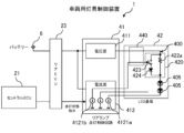
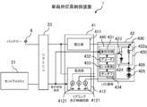
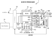
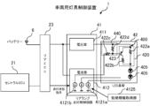
- FIG. 5B shows a case where the switch 423 shown in FIG. 5A is configured using a transistor.
- the emitter of the transistor is connected to the voltage source 411, and the collector is connected to the resistor element 422b.
- the base of the transistor is connected to the second constant current source 4121b via the resistor element 422c, and to the voltage source 411 via the resistor element 422d.
- a voltage determined by the voltage value of the voltage source 411, the value of the current supplied from the second constant current source 4121b, the resistance value of the resistor element 422c, and the resistance value of the resistor element 422d is applied to the base of the transistor. That is, in the vehicle lamp control device 1 shown in the figure, the aforementioned resistance value control circuit 440 is configured by the resistor element 422c and the resistor element 422d.
- the switch 423 is configured using a PNP type transistor. Therefore, when the value of the current supplied from the second constant current source 4121b is small and the voltage drop across the resistor element 422d is equal to or less than a predetermined value, the switch 423 is turned off, and when the value of the current is large and the voltage drop across the resistor element 422d exceeds a predetermined value, the switch 423 is turned on.
- the switch 423 may be configured using other types of elements, such as a field-effect transistor (FET).
- FET field-effect transistor
- the drain is connected to the voltage source 411 and the source is connected to the resistive element 422b.
- the gate is connected to the second constant current source 4121b via the resistive element 422c and to the voltage source 411 via the resistive element 422d.
- the on/off state of the switch 423 can be controlled by changing the value of the current supplied from the second constant current source 4121b.
- the mechanism for controlling the resistance value of the resistance circuit 420 in response to the lighting state instruction can be simply configured using a resistive element and the switch 423.
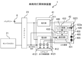
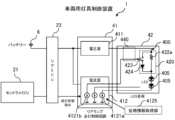
- FIG. 5C shows another example of the configuration of the vehicle lamp control device 1.
- the resistor element 422b connected in series to the switch 423 of the resistor circuit 420 in FIG. 5B is replaced with a diode 424 connected in the forward direction to the LED string 400.
- the resistance value of the resistor circuit 420 when the switch 423 is off is the resistance value of the resistor element 422a.
- the resistance value of this resistor circuit 420 is zero.
- a resistor element may be connected in series to the switch 423.
- the resistance value control circuit 440 in this resistor circuit 420 may be, for example, the circuit shown in FIG. 5B (a circuit formed by resistor elements 422c and 422d).
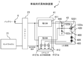
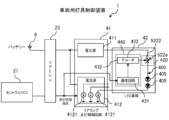
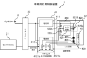
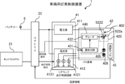
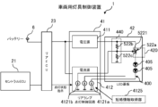
- FIG. 5D shows another example of the configuration of the vehicle lighting control device 1.
- the resistance value of the resistor circuit 420 connected to the LED string 400 is changed by a variable resistor element 522a connected in series to the LED string 400.
- a potentiometer hereinafter referred to as an “analog potentiometer” that sets the resistance value by an analog value (voltage value) is used as the variable resistor element 522a.
- input terminal 5221 for the analog value of variable resistance element 522a is connected to second constant current source 4121b.
- a voltage obtained by dividing the voltage of voltage source 411 by the resistance value of resistance element 522b and the resistance value of resistance element 522c is applied to input terminal 5221.
- the resistance value of resistance element 522b and the resistance value of resistance element 522c are set, for example, according to the range of resistance values required for resistance circuit 420.
- resistance value control circuit 440 is composed of resistance element 522b and resistance element 522c.
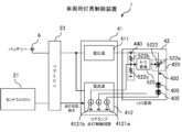
- the vehicle lamp control device 1 shown in FIG. 5E is similar to FIG. 5D in that the resistance value of the resistor circuit 420 connected to the LED string 400 is changed by a variable resistor element 522a connected in series to the LED string 400.
- a potentiometer hereinafter referred to as a "digital potentiometer” that sets the resistance value by inputting a digital value that specifies the resistance value is used as the variable resistor element 522a.
- the analog voltage value divided by resistor elements 522b and 522c is converted to a digital value by A/D conversion circuit 525, and the converted digital value is input to digital value input terminal 5222 of variable resistor element 522a.
- resistance value control circuit 440 is composed of resistor elements 522b, 522c, and A/D conversion circuit 525.
- the mechanism for changing the resistance value of the resistive element 422 connected to the LED string 400 in response to the illumination state instruction from the rear ECU 23 can be simply configured using a variable resistive element such as an analog potentiometer or a digital potentiometer. Furthermore, if a digital potentiometer is used as the variable resistive element 522a, the advantages of the digital potentiometer (high accuracy, high resolution, small size, high stability, long life, high reliability, etc.) can be enjoyed.
- the resistance values of resistor elements 422a and 422b are fixed, so the resistance value of resistor circuit 420 can only be switched in stages (discontinuously).
- variable resistor elements are used, so the resistance value of resistor circuit 420 can be changed continuously. This allows the value of resistor circuit 420 to be finely controlled, and for example, when the lighting state of the light-emitting elements is finely controlled, such as when displaying animation, the resistance value of resistor circuit 420 can be made to accurately follow changes in the lighting state of the light-emitting elements.
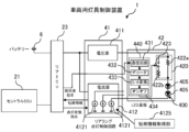
- FIGS. 6A to 6D show another example configuration of the vehicle lamp control device 1.
- the constant current source 4121 second constant current source 4121b
- the LED board 42 has a communication function, and receives a lighting state instruction from the rear ECU 23. In response to the received lighting state instruction, the LED board 42 controls a switch to change the resistance value of the resistor circuit 420.
- the resistance circuit 420 in the vehicle lamp control device 1 shown in FIG. 6A is the same as that shown in FIG. 5A or 5B.
- the LED board 42 is provided with a communication circuit 431 (such as a CAN transceiver) that receives a lighting state instruction, a decoder circuit 432 that decodes the lighting state instruction, a D/A conversion circuit 433 that converts the decoded digital value into an analog value, and an on/off control circuit 434 that controls the switch 423 based on the converted analog value.
- a communication circuit 431 such as a CAN transceiver
- decoder circuit 432 that decodes the lighting state instruction
- a D/A conversion circuit 433 that converts the decoded digital value into an analog value
- an on/off control circuit 434 that controls the switch 423 based on the converted analog value.
- the lighting state instruction received by the communication circuit 431 includes, for example, a parameter that instructs the switch 423 to be turned on or off.
- the D/A conversion circuit 433 generates an analog value according to the value of the parameter and inputs it to the on/off control circuit 434.
- the resistance value control circuit 440 is composed of the communication circuit 431, the decoder circuit 432, the D/A conversion circuit 433, and the on/off control circuit 434.
- the mechanism for changing the resistance value of the resistor circuit 420 in response to the lighting state command from the rear ECU 23 can also be realized by the configuration shown in the figure. Furthermore, when such a configuration is used, the above mechanism can be realized without consuming the resources (constant current source) of the current source 412.
- the resistance element 422b of the resistance circuit 420 in FIG. 6A is replaced with a forward-connected diode 424.
- the resistance value of the resistance circuit 420 when the switch 423 is on can be made almost zero.
- the resistance value of the resistance circuit 420 when the switch 423 is on can be made a predetermined value greater than zero.
- the resistance value control circuit 440 is composed of a communication circuit 431, a decoder circuit 432, a D/A conversion circuit 433, and an on/off control circuit 434.
- the resistance circuit 420 is configured using a variable resistance element 522a.
- FIG. 6C shows a case where an analog potentiometer is used as the variable resistance element 522a, similar to FIG. 5D.
- the LED board 42 is provided with a communication circuit 431 (such as a CAN transceiver) that receives lighting state instructions, a decoder circuit 432 that decodes the lighting state instructions, and a D/A conversion circuit 433 that converts the decoded digital value into an analog value and inputs it to the analog value input terminal 5221 of the variable resistance element 522a.
- the resistance value control circuit 440 is composed of the communication circuit 431, the decoder circuit 432, and the D/A conversion circuit 433.
- FIG. 6D shows an example in which a digital potentiometer is used as the variable resistance element 522a, similar to FIG. 5E.
- the LED board 42 is provided with a communication circuit 431 (such as a CAN transceiver) that receives the lighting state instruction, and a decoder circuit 432 that decodes the lighting state instruction and inputs the decoded digital value to the digital value input terminal 5222 of the variable resistance element 522a.
- the resistance value control circuit 440 is composed of the communication circuit 431 and the decoder circuit 432.
- the vehicle lamp control device 1 of this embodiment changes the resistance value of the resistor circuit 420 so that the change in the voltage value (Vk) applied to the first constant current source 4121a is suppressed when the value of the current supplied to the LED 405 changes. Therefore, even when the lighting control of the LED 405 is performed in various ways, such as by animation, the voltage value applied to the first constant current source 4121a can be maintained within a predetermined range.
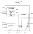
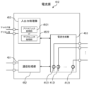
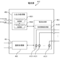
- FIG. 7 is a block diagram showing an example of the configuration of the current source 412.
- the illustrated current source 412 is configured, for example, using a sink driver IC.
- the illustrated current source 412 includes a communication processing unit 451, an input/output processing unit 452, and a current generating unit 453.
- the communication processing unit 451 functions, for example, as a CAN transceiver.
- the communication processing unit 451 communicates with the rear ECU 23, such as receiving information (such as lighting state instructions) sent from the rear ECU 23.
- the information received by the communication processing unit 451 from the rear ECU 23 is notified to the current generating unit 453, for example.
- the input/output processing unit 452 includes an analog input processing unit 4521 and a digital input processing unit 4522.
- the analog input processing unit 4521 accepts analog values input from the outside, and notifies the current generating unit 453 of the accepted analog values.
- the digital input processing unit 4522 accepts digital values input from the outside, and notifies the current generating unit 453 of the accepted digital values.
- the current generating unit 453 controls the value of the current output from the constant current source 4121 based on information (such as lighting state instructions) notified from the communication processing unit 451 and information notified from the input/output processing unit 452.
- the above description focuses on one LED row 400 provided on the LED board 42, but if multiple LED rows 400 are provided on the LED board 42, the configuration described above may be applied to each LED row 400.
- the vehicle lamp control device 1 of this embodiment includes a first constant current source that supplies a constant current to a light-emitting element used in a vehicle lamp, a resistance circuit connected in series to the light-emitting element and the first constant current source, a current value control circuit that controls the value of the current of the first constant current source in response to a lighting state instruction that indicates the lighting state of the light-emitting element, and a resistance value control circuit that changes the resistance value of the resistance circuit so that changes in the value of the voltage applied to the first constant current source are suppressed when the value of the current supplied to the light-emitting element changes.
- the resistance value of the resistor circuit can be changed so that the change in the value of the voltage applied to the first constant current source is suppressed when the value of the current supplied to the light-emitting element changes.
- the value of the voltage applied to the first constant current source can be maintained within a predetermined range. Therefore, it is possible to prevent an increase in power consumption and heat generation, and the failure of the light-emitting element, which occurs when the value of the voltage applied to the first constant current source becomes too high or too low, from occurring.
- the vehicle lamp control device 1 of this embodiment further includes a second constant current source that supplies a current according to the lighting state instruction, and the resistance value control circuit changes the resistance value of the resistor circuit according to the value of the current supplied by the second constant current source.
- the vehicle lighting control device 1 changes the resistance value of the resistor circuit by using a constant current source (second constant current source) included in a current source having multiple constant current sources, so that a mechanism for controlling the resistance value of the resistor circuit in response to a lighting state instruction can be realized with a simple configuration.
- a constant current source second constant current source
- the resistance circuit of the vehicle lamp control device 1 of this embodiment includes a first resistance element connected in series to the light-emitting element, a second resistance element connected in series to the light-emitting element and in parallel to the first resistance element, and a switch, and the resistance value control circuit turns the switch on and off depending on the current value of the second constant current source.
- the above configuration makes it possible to realize a mechanism for controlling the resistance value of the resistor circuit in response to a lighting state instruction with a simple configuration.
- the resistance circuit of the vehicle lamp control device 1 of this embodiment includes a first resistance element connected in series to the light-emitting element, and a diode and switch connected in series to the light-emitting element in the forward direction and connected in parallel to the first resistance element, and the resistance value control circuit turns the switch on and off depending on the current value of the second constant current source.
- the above configuration makes it possible to realize a mechanism for controlling the resistance value of the resistor circuit in response to changes in the temperature of the light-emitting element with a simple configuration.
- the resistance value of the resistor circuit can be set to zero by passing a current through the diode.
- the resistance circuit of the vehicle lamp control device 1 of this embodiment includes a variable resistance element whose resistance value changes according to the control voltage, and the resistance value control circuit outputs a control voltage according to the current value of the second constant current source.
- variable resistance element By using a variable resistance element, it is possible to realize a mechanism for changing the resistance value of a resistance circuit in response to a lighting state instruction with a simple configuration.
- first constant current source and the second constant current source of the vehicle lamp control device 1 of this embodiment are different constant current sources in a single integrated circuit that has multiple constant current sources.
- the mechanism for changing the resistance value of the resistor circuit in response to lighting state instructions can be realized with a simple configuration using a single integrated circuit equipped with multiple constant current sources such as driver ICs.
- the vehicle lighting control device 1 of this embodiment further includes a receiving circuit that receives lighting state instructions from other devices that are communicatively connected, and the resistance value control circuit changes the resistance value of the resistor circuit in response to the lighting state instructions received by the receiving circuit.
- another device such as the rear ECU directly controls the resistance value of the resistor circuit, so it is possible to realize a mechanism for changing the resistance value of the resistor circuit in response to a lighting state instruction without consuming resources (constant current source) of the current source (driver IC).
- the resistance circuit of the vehicle lighting control device 1 of this embodiment includes a first resistance element connected in series to the light-emitting element, a second resistance element connected in series to the light-emitting element and in parallel to the first resistance element, and a switch, and the resistance value control circuit is configured to turn the switch on and off in response to a lighting state instruction.
- the above configuration makes it possible to realize a mechanism for controlling the resistance value of the resistor circuit in response to a lighting state instruction with a simple configuration.
- the vehicle lighting control device 1 of this embodiment also includes a second information processing device communicatively connected to the first information processing device, and the second information processing device stores software for implementing a process for generating a lighting state instruction, receives software update information from the first information processing device, and updates the software based on the received update information to content that causes a change in the value of the current supplied to the light-emitting element before and after the update.
- Changes in the value of the current supplied to the light-emitting element also occur when software for implementing the process of generating a lighting state instruction, which is stored in the second information processing device based on information received from the first information processing device, is updated. With the above configuration, even in such cases, the value of the voltage applied to the first constant current source can be maintained within a predetermined range.
- the temperature of the LED 405 changes, for example, when the ambient temperature changes or when the lighting method of the LED 405 is changed in response to a lighting state instruction from the rear ECU 23, causing a change in the value of the current supplied to the LED 405.
- a specific explanation will be given with reference to Figures 8A and 8B about situations in which a change in the temperature of the LED 405 leads to increased power consumption and heat generation or failure to light up.
- the following considers a case in which the temperature of the LED 405 rises (the temperature of the LED 405 rises from a low temperature (Tb) to a high temperature (Ta (>Tb)).
- the resistance value of the resistor element 422 of the LED board 42 is designed based on low temperature (Tb), that is, the value of the resistor element 422 is designed so that the voltage value (Vk) of the constant current source 4121 is appropriate when the temperature of the LED 405 is low (Tb).
- Tb low temperature
- Vk voltage value of the constant current source 4121
- the resistance value of the resistor element 422 of the LED board 42 is designed based on a high temperature (Ta), that is, the value of the resistor element 422 is designed so that the voltage value (Vk) of the constant current source 4121 is appropriate when the temperature of the LED 405 is high (Ta).
- Ta high temperature
- Vk voltage value of the constant current source 4121
- resistor circuit 420 a resistor circuit capable of changing the resistance value in the LED string 400.
- FIG. 9A shows an example of the configuration of the vehicle lamp control device 1 of this embodiment.
- a resistance circuit 420 is provided in series with the LEDs 405 that make up the LED string 400, and a circuit that controls the resistance value of the resistance circuit 420 (hereinafter referred to as the "resistance control circuit 440").
- the resistance circuit 420 includes a resistance element 422a, a resistance element 422b that is connected in parallel with the resistance element 422a, and a switch 423 that is connected in series with the resistance element 422b and turns on and off the connection to the LED 405.
- the specific configuration of the resistance control circuit 440 will be described later.
- a temperature sensor 45 is provided at a predetermined position on the LED board 42 to acquire information indicating the temperature around the LED 405 (hereinafter referred to as "temperature information").
- the temperature information acquired (measured) by the temperature sensor 45 is notified (input) to the current source 412 of the rear lamp lighting control circuit 41 via a circuit such as wiring or a communication line.
- the temperature information does not necessarily have to be the temperature of the LED 405 element itself, but may be any information that can indirectly identify or estimate the temperature of the LED 405, such as the temperature around the LED 405.
- the temperature information may be acquired by other types of sensors based on other principles, such as an optical sensor, a total radiation thermometer, an optical pyrometer, an infrared thermometer, etc.
- the on/off control of the switch 423 is performed by changing the current value of another constant current source 4121 (hereinafter also referred to as the "second constant current source 4121b"), which is different from the constant current source 4121 (hereinafter also referred to as the "first constant current source 4121a”) that supplies current to the LED string 400, among the multiple constant current sources 4121 included in the current source 412.
- second constant current source 4121b another constant current source 4121
- first constant current source 4121a which supplies current to the LED string 400
- the current source 412 controls the current value of the second constant current source 4121b based on the notified temperature information, thereby controlling the on/off of the switch 423 and switching the resistance value of the resistor circuit 420.
- the current source 412 changes the value of the current of the second constant current source 4121b to turn off the switch 423 and increase the resistance value of the resistor circuit 420 (increasing the voltage drop in the resistor circuit 420), thereby preventing an increase in the voltage applied to the first constant current source 4121a.
- the current source 412 turns on the switch 423 by changing the current value of the second constant current source 4121b to reduce the resistance value of the resistance circuit 420 (reducing the voltage drop in the resistance circuit 420), thereby preventing a drop in the voltage applied to the first constant current source 4121a.
- the boundary value (threshold value) used to determine whether the temperature of the LED 405 is high or low is set according to, for example, the characteristics of the LED 405 and the characteristics of the current source 412 (constant current source 4121).
- the resistance value of the resistor circuit 420 is changed so that the change in the value of the voltage applied to the first constant current source 4121a due to a change in the temperature of the LED 405 is suppressed. Therefore, even if the temperature of the LED 405 changes, the value of the voltage applied to the first constant current source 4121a can be maintained within a predetermined range. Therefore, it is possible to prevent an increase in power consumption and heat generation due to the voltage value (Vk) applied to the first constant current source 4121a becoming excessive. In addition, it is possible to prevent the LED 405 from going unlit due to the voltage value (Vk) applied to the first constant current source 4121a being lower (too small) than the value necessary for the first constant current source 4121a to operate properly.
- the current source 412 changes the current value of the second constant current source 4121b, which is different from the first constant current source 4121a, among the multiple constant current sources 4121 included in the current source 412, that is, changes the resistance value of the resistance circuit 420 by using the second constant current source 4121b, which is one of the constant current sources 4121 of the current source 412. Therefore, a mechanism for controlling the resistance value of the resistance circuit 420 in response to a lighting state instruction can be realized with a simple configuration.
- FIG. 9B shows a case where the switch 423 shown in FIG. 9A is configured using a transistor.
- the emitter of the transistor is connected to the voltage source 411, and the collector is connected to the resistor element 422b.
- the base of the transistor is connected to the second constant current source 4121b via the resistor element 422c, and to the voltage source 411 via the resistor element 422d.
- a voltage determined by the voltage value of the voltage source 411, the value of the current supplied from the second constant current source 4121b, the resistance value of the resistor element 422c, and the resistance value of the resistor element 422d is applied to the base of the transistor. That is, in the example shown in the figure, the resistance value control circuit 440 is configured by the resistor elements 422c and 422d.
- the switch 423 is configured using a PNP type transistor. Therefore, when the value of the current supplied from the second constant current source 4121b is small and the voltage drop across the resistor element 422d is equal to or less than a predetermined value, the switch 423 is turned off, and when the value of the current is large and the voltage drop across the resistor element 422d exceeds a predetermined value, the switch 423 is turned on.
- the switch 423 may be configured using other types of elements, such as a field-effect transistor (FET).
- FET field-effect transistor
- the drain is connected to the voltage source 411 and the source is connected to the resistive element 422b.
- the gate is connected to the second constant current source 4121b via the resistive element 422c and to the voltage source 411 via the resistive element 422d.
- the on/off state of the switch 423 can be controlled by changing the value of the current supplied from the second constant current source 4121b.
- the mechanism for controlling the resistance value of the resistance circuit 420 in response to temperature information can be simply configured using a resistance element and the switch 423.
- FIG. 9C shows another example of the configuration of the vehicle lamp control device 1.
- the resistor element 422b connected in series to the switch 423 of the resistor circuit 420 in FIG. 9B is replaced with a diode 424 connected in the forward direction to the LED string 400.
- the resistance value of the resistor circuit 420 when the switch 423 is off is the resistance value of the resistor element 422a.
- the resistance value of this resistor circuit 420 is zero.
- a resistor element may be connected in series to the switch 423.
- the resistance value control circuit 440 in this resistor circuit 420 may be, for example, the circuit shown in FIG. 9B (a circuit formed by resistor elements 422c and 422d).
- FIG. 9D shows another example of the configuration of the vehicle lighting control device 1.
- the resistance value of the resistor circuit 420 connected to the LED string 400 is changed by a variable resistor element 522a connected in series to the LED string 400.
- a potentiometer hereinafter referred to as an “analog potentiometer” that sets the resistance value by an analog value (voltage value) is used as the variable resistor element 522a.
- input terminal 5221 for the analog value of variable resistance element 522a is connected to second constant current source 4121b.
- a voltage obtained by dividing the voltage of voltage source 411 by the resistance value of resistance element 522b and the resistance value of resistance element 522c is applied to input terminal 5221.
- the resistance value of resistance element 522b and the resistance value of resistance element 522c are set, for example, according to the range of resistance values required for resistance circuit 420.
- resistance value control circuit 440 is composed of resistance element 522b and resistance element 522c.
- the vehicle lamp control device 1 shown in FIG. 9E is similar to FIG. 9D in that the resistance value of the resistor circuit 420 connected to the LED string 400 is changed by a variable resistor element 522a connected in series to the LED string 400.
- a potentiometer hereinafter referred to as a "digital potentiometer” that sets the resistance value by inputting a digital value that specifies the resistance value is used as the variable resistor element 522a.
- the analog voltage value divided by resistor elements 522b and 522c is converted to a digital value by A/D conversion circuit 525, and the converted digital value is input to digital value input terminal 5222 of variable resistor element 522a.
- resistance value control circuit 440 is composed of resistor elements 522b, 522c, and A/D conversion circuit 525.
- the mechanism for changing the resistance value of the resistance circuit 420 in response to the short circuit information can be simply configured using a variable resistance element such as an analog potentiometer or a digital potentiometer.
- a digital potentiometer is used as the variable resistance element 522a, the advantages of the digital potentiometer (high accuracy, high resolution, small size, high stability, long life, high reliability, etc.) can be enjoyed.
- resistive circuit 420 In addition, in the configurations shown in Figures 9A to 9C described above, the resistance values of resistive elements 422a and 422b are fixed, so the resistance value of resistive circuit 420 can only be changed in stages (discontinuously). In contrast, the configurations shown in Figures 9D and 9E use variable resistive elements, so the resistance value of resistive circuit 420 can be changed continuously. Therefore, the value of resistive circuit 420 can be finely controlled according to temperature information.
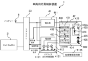
- FIGS. 10A to 10D show another example of the configuration of the vehicle lamp control device 1.
- the constant current source 4121 second constant current source 4121b
- the short circuit information acquisition unit 4125 of the rear lamp lighting control circuit 41 notifies the rear ECU 23 of the temperature information acquired by the temperature sensor 45, and the rear ECU 23 transmits an instruction to switch the resistance value of the resistor circuit 420 (hereinafter referred to as a "resistance value instruction") to the LED board 42 based on the notified temperature information.
- the LED board 42 switches the resistance value of the resistor circuit 420 based on the resistance value instruction received from the rear ECU 23.
- the resistance circuit 420 in the vehicle lamp control device 1 shown in FIG. 10A is, for example, the same as that shown in FIG. 9A or FIG. 9B.
- the temperature information acquired (measured) by the temperature sensor 45 is notified to the rear ECU 23 via a circuit such as wiring or a communication line.
- the LED board 42 is provided with a communication circuit 431 (such as a CAN transceiver) that receives a lighting state instruction, a decoder circuit 432 that decodes the received lighting state instruction, a D/A conversion circuit 433 that converts the decoded digital value into an analog value, and an on/off control circuit 434 that controls the switch 423 based on the converted analog value.
- a communication circuit 431 such as a CAN transceiver
- the lighting state instruction received by the communication circuit 431 includes, for example, a parameter that instructs the switch 423 to be turned on or off.
- the D/A conversion circuit 433 generates an analog value according to the value of the above parameter and inputs it to the on/off control circuit 434.
- the resistance value control circuit 440 is composed of the communication circuit 431, the decoder circuit 432, the D/A conversion circuit 433, and the on/off control circuit 434.
- the mechanism for controlling the resistance value of resistor circuit 420 in response to temperature information can also be realized by the configuration shown in the figure. Furthermore, when such a configuration is used, the above mechanism can be realized without consuming the resources (constant current source) of current source 412.
- the resistance element 422b of the resistance circuit 420 in FIG. 10A is replaced with a forward-connected diode 424.
- the resistance value of the resistance circuit 420 when the switch 423 is on can be set to zero.
- the resistance value of the resistance circuit 420 when the switch 423 is on can be set to a predetermined value greater than zero.
- the resistance circuit 420 is configured using a variable resistance element 522a.
- FIG. 10C shows a case where an analog potentiometer is used as the variable resistance element 522a, as in FIG. 9D.
- the LED board 42 is provided with a communication circuit 431 (such as a CAN transceiver) that receives the resistance value instruction, a decoder circuit 432 that decodes the resistance value instruction, and a D/A conversion circuit 433 that converts the decoded digital value into an analog value and inputs it to the analog value input terminal 5221 of the variable resistance element 522a.
- the resistance value control circuit 440 is composed of the communication circuit 431, the decoder circuit 432, and the D/A conversion circuit 433.
- FIG. 10D shows an example in which a digital potentiometer is used as the variable resistance element 522a, similar to FIG. 9E.
- the LED board 42 is provided with a communication circuit 431 (such as a CAN transceiver) that receives the resistance value instruction, and a decoder circuit 432 that decodes the resistance value instruction and inputs the decoded digital value to the digital value input terminal 5222 of the variable resistance element 522a.
- the resistance value control circuit 440 is composed of the communication circuit 431 and the decoder circuit 432.
- the vehicle lamp control device 1 of this embodiment changes the resistance value of the resistor circuit 420 so as to suppress changes in the voltage value (Vk) applied to the first constant current source 4121a due to changes in the temperature of the LED 405, so that the voltage value applied to the first constant current source 4121a can be maintained within a predetermined range even when the temperature of the LED 405 changes.
- This makes it possible to prevent an increase in power consumption and heat generation due to the voltage value (Vk) applied to the first constant current source 4121a being excessive, and the LED 405 from going unlit due to the voltage value (Vk) applied to the first constant current source 4121a being below (too small) the value required for the first constant current source 4121a to operate properly.
- FIG. 11 is a block diagram showing an example of the configuration of the current source 412.
- the illustrated current source 412 is configured, for example, using a sink driver IC.
- the illustrated current source 412 includes a communication processing unit 451, an input/output processing unit 452, and a current generating unit 453.
- the communication processing unit 451 functions, for example, as a CAN transceiver.
- the communication processing unit 451 communicates with the rear ECU 23, such as receiving information (resistance value instructions, etc.) sent from the rear ECU 23.
- the information received by the communication processing unit 451 from the rear ECU 23 is notified to the current generating unit 453, for example.
- the input/output processing unit 452 includes an analog input processing unit 4521 and a digital input processing unit 4522.
- the analog input processing unit 4521 accepts an analog value input from the outside (for example, an analog value input from the temperature sensor 45 if the temperature sensor 45 of the LED board 42 is of a type that outputs an analog value (analog voltage value) indicating temperature) and notifies the current generating unit 453 of the accepted analog value.
- the digital input processing unit 4522 accepts a digital value input from the outside and notifies the current generating unit 453 of the accepted digital value (for example, a digital value input from the temperature sensor 45 if the temperature sensor 45 of the LED board 42 is of a type that outputs a digital value indicating temperature).
- the current generating unit 453 controls the value of the current output from the constant current source 4121 based on information (temperature information, etc.) notified from the input/output processing unit 452 and information (resistance value instruction, etc.) notified from the communication processing unit 451.
- the above description focuses on one LED row 400, but if multiple LED rows 400 are provided on the LED board 42, the mechanism described above may be applied to each LED row 400.
- the vehicle lamp control device 1 of this embodiment includes a first constant current source that supplies a constant current to a light-emitting element used in a vehicle lamp, a resistance circuit connected in series to the light-emitting element and the first constant current source, a current value control circuit that controls the value of the current of the first constant current source, and a resistance value control circuit that changes the resistance value of the resistance circuit so that changes in the value of the voltage applied to the first constant current source are suppressed when the temperature around the light-emitting element changes.
- the vehicle lighting control device 1 changes the resistance value of the resistor circuit so as to suppress changes in the value of the voltage applied to the first constant current source when the temperature of the light-emitting element changes. Therefore, even if the temperature of the light-emitting element changes, the value of the voltage applied to the first constant current source can be maintained within a predetermined range. Therefore, it is possible to prevent increased power consumption and heat generation, and the failure of the light-emitting element, which occur when the value of the voltage applied to the first constant current source becomes too high or too low.
- the vehicle lighting control device 1 of this embodiment further includes a second constant current source that supplies a current according to the ambient temperature of the light-emitting element, and the resistance value control circuit changes the resistance value of the resistor circuit according to the value of the current supplied by the second constant current source.
- the vehicle lighting control device 1 changes the resistance value of the resistor circuit by using a constant current source (second constant current source) included in a current source having multiple constant current sources, so that a mechanism for controlling the resistance value of the resistor circuit according to the ambient temperature of the light-emitting element can be realized with a simple configuration.
- a constant current source second constant current source
- the resistance circuit of the vehicle lighting control device 1 of this embodiment includes a first resistance element connected in series to the light-emitting element, a second resistance element connected in series to the light-emitting element and in parallel to the first resistance element, and a switch, and the resistance value control circuit turns the switch on and off depending on the current value of the second constant current source.
- the above configuration makes it possible to realize a mechanism for controlling the resistance value of the resistor circuit according to the ambient temperature of the light-emitting element with a simple configuration.
- the resistance circuit of the vehicle lamp control device 1 of this embodiment includes a first resistance element connected in series to the light-emitting element, and a diode and switch connected in series to the light-emitting element in the forward direction and connected in parallel to the first resistance element, and the resistance value control circuit turns the switch on and off depending on the current value of the second constant current source.
- the above configuration makes it possible to realize a mechanism for controlling the resistance value of the resistor circuit according to the ambient temperature of the light-emitting element with a simple configuration.
- the resistance value of the resistor circuit can be set to zero by passing a current through the diode.
- the resistance circuit of the vehicle lamp control device 1 of this embodiment includes a variable resistance element whose resistance value changes according to the control voltage, and the resistance value control circuit outputs a control voltage according to the current value of the second constant current source.
- first constant current source and the second constant current source of the vehicle lamp control device 1 of this embodiment are different constant current sources in a single integrated circuit that has multiple constant current sources.
- a mechanism for controlling the resistance value of the resistor circuit according to the ambient temperature of the light-emitting element can be realized with a simple configuration using a single integrated circuit equipped with multiple constant current sources such as driver ICs.
- the vehicle lighting control device 1 of this embodiment further includes a temperature information acquisition circuit that acquires temperature information indicating the temperature around the light-emitting element, a notification circuit that notifies other devices connected in a communicative manner of the temperature information, and a receiving circuit that receives a resistance value instruction indicating the resistance value of the resistance circuit that is notified by the other devices based on the temperature information, and the resistance value control circuit changes the resistance value of the resistance circuit in response to the resistance value instruction received by the receiving circuit.
- another device such as the rear ECU directly controls the resistance value of the resistor circuit, so it is possible to realize a mechanism for changing the resistance value of the resistor circuit in response to a lighting state instruction without consuming resources (constant current source) of the current source (driver IC).
- the resistance circuit of the vehicle lamp control device 1 of this embodiment includes a first resistance element connected in series to the light-emitting element, a second resistance element connected in series to the light-emitting element and in parallel to the first resistance element, and a switch, and the resistance value control circuit turns the switch on and off in response to a resistance value instruction.
- the above configuration makes it possible to realize a mechanism for controlling the resistance value of a resistor circuit in response to a resistance value instruction with a simple configuration.
- the LED string 400 includes two LEDs 405a and 405b connected in series, and the value of the resistor element 422 is designed so that the voltage value (Vk) of the constant current source 4121 is appropriate when these LEDs are lit normally.
- the above problem is solved by providing the LED string 200 with a resistor circuit that can change the resistance value.
- the specific configuration of the vehicle lamp control device 1 of this embodiment is described below.
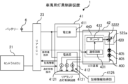
- FIG. 13A shows an example of the configuration of the vehicle lighting control device 1 of this embodiment.
- a resistance circuit 420 is provided in series with the LEDs 405 that make up the LED string 400, and a circuit that controls the resistance value of the resistance circuit 420 (hereinafter referred to as the "resistance control circuit 440").
- the resistance circuit 420 includes a resistance element 422a, a resistance element 422b that is connected in parallel with the resistance element 422a, and a switch 423 that is connected in series with the resistance element 422b and turns on and off the connection to the LED 405.
- the specific configuration of the resistance control circuit 440 will be described later.
- the on/off of the switch 423 is controlled by changing the current value of another constant current source 4121 (hereinafter also referred to as the "second constant current source 4121b"), which is different from the constant current source 4121 (hereinafter also referred to as the "first constant current source 4121a”) that supplies current to the LED string 400, among the multiple constant current sources 4121 included in the current source 412.
- second constant current source 4121b another constant current source 4121
- first constant current source 4121a which supplies current to the LED string 400
- the current source 412 has a short circuit information acquisition unit 4125 that acquires information indicating whether or not a short circuit has occurred in the LEDs 405 that constitute the LED string 400 (hereinafter referred to as "short circuit information").
- the short circuit information acquisition unit 4125 may be, for example, a short circuit detection circuit provided in the driver IC that constitutes the current source 412, or a circuit provided separately in the rear lamp lighting control circuit 41.
- the short circuit information acquisition unit 4125 monitors the voltage value (Vk) of the first constant current source 4121a of the current source 412 to determine whether or not a short circuit has occurred in the LED 405 of the LED string 400. For example, the short circuit information acquisition unit 4125 detects whether or not a short circuit has occurred in the LED 405 of the LED string 400 connected to the first constant current source 4121a based on whether or not the voltage value (Vk) of the first constant current source 4121a is higher than a predetermined voltage.
- the above-mentioned predetermined voltage is set based on, for example, the voltage value applied by the voltage source 411 to the LED string 400, the resistance value of the resistor circuit 420, the voltage drop of the LED 405, and the constant current value of the first constant current source 4121a.
- the current source 412 controls the current value of the second constant current source 4121b in accordance with the short circuit information acquired by the short circuit information acquisition unit 4125, and switches the switch 423 on and off.
- the current source 412 detects based on the short circuit information that none of the LEDs 405 constituting the LED string 400 are short circuited, it maintains the current value of the second constant current source 4121b at a predetermined value, thereby turning on the switch 423 to reduce the resistance value of the resistor circuit 420 (reducing the voltage drop in the resistor circuit 420), and maintains the voltage value (Vk) applied to the first constant current source 4121a at an appropriate value.
- the current source 412 when the current source 412 detects from the short circuit information that one of the LEDs 405 constituting the LED string 400 is short circuited, it controls the value of the current of the second constant current source 4121b to turn off the switch 423 and increase the resistance value of the resistance circuit 420 (increase the voltage drop in the resistance circuit 420), thereby preventing an increase in the value of the voltage (Vk) applied to the first constant current source 4121a.
- the short-circuit information acquisition unit 4125 may acquire information indicating whether or not at least any of the multiple LEDs 405 is short-circuited as short-circuit information, and control the resistance value of the resistance circuit 420 according to the magnitude of the voltage drop determined from the acquired short-circuit information. In this way, even if two or more LEDs 405 that make up the same LED string 400 short-circuit at the same time, it is possible to appropriately suppress changes in the value of the voltage (Vk) applied to the first constant current source 4121a.
- the current source 412 stops the supply of current from the first constant current source 4121a to the LED string 400, or treats the LED string 400 as a minute resistance load and controls the resistance value of the resistance circuit 420 to suppress changes in the value of the voltage (Vk) applied to the first constant current source 4121a, in the same way as when some of the LEDs 405 are short-circuited.
- the illustrated vehicle lighting control device 1 controls the value of the current supplied from the second constant current source in response to the short circuit information to control the resistance value of the resistor circuit 420, thereby suppressing changes in the value of the voltage (Vk) applied to the first constant current source 4121a. Therefore, even if the LED 405 that constitutes the LED string 400 is short-circuited, the value of the voltage (Vk) applied to the first constant current source 4121a can be maintained at an appropriate value.
- the current source 412 changes the current value of the second constant current source 4121b, which is different from the first constant current source 4121a, among the multiple constant current sources 4121 included in the current source 412, that is, changes the resistance value of the resistance circuit 420 by using the second constant current source 4121b, which is one of the constant current sources 4121 of the current source 412. Therefore, a mechanism for controlling the resistance value of the resistance circuit 420 in response to short-circuit information can be realized with a simple configuration.
- FIG. 13B shows a case where the switch 423 shown in FIG. 13A is configured using a transistor.
- the emitter of the transistor is connected to the voltage source 411, and the collector is connected to the resistor element 422b.
- the base of the transistor is connected to the second constant current source 4121b via the resistor element 422c, and to the voltage source 411 via the resistor element 422d.
- a voltage determined by the voltage value of the voltage source 411, the value of the current supplied from the second constant current source 4121b, the resistance value of the resistor element 422c, and the resistance value of the resistor element 422d is applied to the base of the transistor. That is, in the example shown in the figure, the resistance value control circuit 440 is configured by the resistor elements 422c and 422d.
- the switch 423 is configured using a PNP-type transistor. Therefore, when the value of the current supplied from the second constant current source 4121b is small and the voltage drop across the resistor element 422d is equal to or less than a predetermined value, the switch 423 is turned off, and when the value of the current is large and the voltage drop across the resistor element 422d exceeds a predetermined value, the switch 423 is turned on.
- the switch 423 may be configured using other types of elements, such as a field-effect transistor (FET).
- FET field-effect transistor
- the drain is connected to the voltage source 411 and the source is connected to the resistive element 422b.
- the gate is connected to the second constant current source 4121b via the resistive element 422c and to the voltage source 411 via the resistive element 422d.
- the on/off state of the switch 423 can be controlled by changing the value of the current supplied from the second constant current source 4121b.
- the mechanism for controlling the resistance value of the resistor circuit in response to the short circuit information can be simply configured using a resistor element and the switch 423.
- FIG. 13C shows another example of the configuration of the vehicle lamp control device 1.
- the resistor element 422b connected in series to the switch 423 of the resistor circuit 420 in FIG. 13B is replaced with a diode 424 connected in the forward direction to the LED string 400.
- the resistance value of the resistor circuit 420 when the switch 423 is off is the resistance value of the resistor element 422a.
- the resistance value of this resistor circuit 420 is zero.
- a resistor element may be connected in series to the switch 423.
- FIG. 13D shows another example of the configuration of the vehicle lighting control device 1.
- the resistance value of the resistor circuit 420 connected to the LED string 400 is changed by a variable resistor element 522a connected in series to the LED string 400.
- a potentiometer hereinafter referred to as an “analog potentiometer” that sets the resistance value by an analog value (voltage value) is used as the variable resistor element 522a.
- the input terminal 5221 of the analog value of the variable resistance element 522a is connected to the second constant current source 4121b.
- a voltage obtained by dividing the voltage of the voltage source 411 by the resistance value of the resistance element 522b and the resistance value of the resistance element 522c is applied to the input terminal 5221.
- the resistance value of the resistance element 522b and the resistance value of the resistance element 522c are set, for example, according to the range of resistance values required for the resistance circuit 420.
- the resistance value control circuit 440 is composed of the resistance element 522b and the resistance element 522c.
- the vehicle lamp control device 1 shown in FIG. 13E is configured so that the resistance value of the resistor circuit 420 connected to the LED string 400 is changed by a variable resistor element 522a connected in series to the LED string 400.
- a potentiometer hereinafter referred to as a "digital potentiometer” that sets the resistance value by inputting a digital value that specifies the resistance value is used as the variable resistor element 522a.
- the analog voltage value divided by resistor elements 522b and 522c is converted to a digital value by A/D conversion circuit 525, and the converted digital value is input to digital value input terminal 5222 of variable resistor element 522a.
- resistance value control circuit 440 is composed of resistor elements 522b, 522c, and A/D conversion circuit 525.
- the mechanism for changing the resistance value of the resistance circuit 420 in response to the short circuit information can be simply configured using a variable resistance element such as an analog potentiometer or a digital potentiometer.
- a digital potentiometer is used as the variable resistance element 522a, the advantages of the digital potentiometer (high accuracy, high resolution, small size, high stability, long life, high reliability, etc.) can be enjoyed.
- resistor circuit 420 can be finely controlled according to the short-circuit information. For example, if multiple LEDs 405 in the same LED string 400 are short-circuited at the same time, the value of resistor circuit 420 can be controlled according to the number of short-circuited LEDs 405.
- FIGS. 14A to 14D show another example of the configuration of the vehicle lamp control device 1.
- the constant current source 4121 second constant current source 4121b
- the current source 412 is used to change the resistance value of the resistor circuit 420.
- the short circuit information acquired by the short circuit information acquisition unit 4125 of the rear lamp lighting control circuit 41 is notified to the rear ECU 23, and the rear ECU 23 transmits an instruction to switch the resistance value of the resistor circuit 420 (hereinafter referred to as a "resistance value instruction”) to the LED board 42 based on the notified short circuit information.
- the LED board 42 switches the resistance value of the resistor circuit 420 based on the resistance value instruction received from the rear ECU 23.
- the resistance circuit 420 in the vehicle lamp control device 1 shown in FIG. 14A is, for example, the same as that shown in FIG. 13A or FIG. 13B.
- the short circuit information acquired by the short circuit information acquisition unit 4125 of the rear lamp lighting control circuit 41 is notified to the rear ECU 23 via a circuit such as wiring or a communication line.
- the LED board 42 is provided with a communication circuit 431 (such as a CAN transceiver) that receives the short circuit information, a decoder circuit 432 that decodes the received short circuit information, a D/A conversion circuit 433 that converts the decoded digital value into an analog value, and an on/off control circuit 434 that controls the switch 423 based on the converted analog value.
- the resistance value instruction received by the communication circuit 431 includes, for example, a parameter that instructs the switch 423 to be turned on or off.
- the D/A conversion circuit 433 generates an analog value according to the value of the above parameter and inputs it to the on/off control circuit 434.
- the resistance value control circuit 440 is composed of the communication circuit 431, the decoder circuit 432, the D/A conversion circuit 433, and the on/off control circuit 434.
- the mechanism for controlling the resistance value of the resistor circuit 420 in response to short circuit information can also be realized by the configuration shown in the figure. Furthermore, when such a configuration is used, the above mechanism can be realized without consuming the resources (constant current source) of the current source 412.
- the resistance element 422b of the resistance circuit 420 in FIG. 14A is replaced with a forward-connected diode 424.
- the resistance value of the resistance circuit 420 when the switch 423 is on can be set to zero.
- the resistance value of the resistance circuit 420 when the switch 423 is on can be set to a predetermined value greater than zero.
- the resistance circuit 420 is configured using a variable resistance element 522a.
- FIG. 14C shows an example in which an analog potentiometer is used as the variable resistance element 522a, similar to FIG. 13D.
- the LED board 42 is provided with a communication circuit 431 (such as a CAN transceiver) that receives the resistance value instruction, a decoder circuit 432 that decodes the resistance value instruction, and a D/A conversion circuit 433 that converts the decoded digital value into an analog value and inputs it to the analog value input terminal 5221 of the variable resistance element 522a.
- the resistance value control circuit 440 is made up of the communication circuit 431, the decoder circuit 432, and the D/A conversion circuit 433.
- FIG. 14D shows an example in which a digital potentiometer is used as the variable resistance element 522a, similar to FIG. 13E.
- the LED board 42 is provided with a communication circuit 431 (such as a CAN transceiver) that receives the resistance value instruction, and a decoder circuit 432 that decodes the resistance value instruction and inputs the decoded digital value to the digital value input terminal 5222 of the variable resistance element 522a.
- the resistance value control circuit 440 is composed of the communication circuit 431 and the decoder circuit 432.
- the vehicle lighting control device 1 of this embodiment changes the resistance value of the resistor circuit 420 so that the change in the value of the voltage (Vk) applied to the first constant current source 4121a is suppressed when the LED 405 is shorted, so that the value of the voltage applied to the first constant current source 4121a can be maintained within a predetermined range even when the LED 405 is shorted. Therefore, it is possible to prevent an increase in power consumption and heat generation caused by the value of the voltage (Vk) applied to the first constant current source 4121a becoming excessive.
- FIG. 15 is a block diagram showing an example of the configuration of the current source 412.
- the illustrated current source 412 is configured, for example, using a sink driver IC.
- the illustrated current source 412 includes a communication processing unit 451, an input/output processing unit 452, and a current generating unit 453.
- the communication processing unit 451 functions, for example, as a CAN transceiver.
- the communication processing unit 451 communicates with the rear ECU 23, such as sending short circuit information to the rear ECU 23 and receiving information (resistance value instructions, etc.) sent from the rear ECU 23.
- the information received by the communication processing unit 451 from the rear ECU 23 is notified to the current generating unit 453, for example.
- the input/output processing unit 452 includes an analog input processing unit 4521 and a digital input processing unit 4522.
- the analog input processing unit 4521 accepts analog values input from the outside, and notifies the current generating unit 453 of the accepted analog values.
- the digital input processing unit 4522 accepts digital values input from the outside, and notifies the current generating unit 453 of the accepted digital values.
- the current generating unit 453 controls the value of the current output from the constant current source 4121 based on information (resistance value instruction, etc.) notified from the communication processing unit 451.
- the current generating unit 453 has a short circuit information acquiring unit 4125 that acquires the short circuit information described above.
- the above description focuses on one LED row 400, but if multiple LED rows 400 are provided on the LED board 42, the mechanism described above may be applied to each LED row 400.
- the vehicle lamp control device 1 of this embodiment includes a first constant current source that supplies a constant current to a light-emitting element used in a vehicle lamp, a resistance circuit connected in series to the light-emitting element and the first constant current source, a current value control circuit that controls the value of the current of the first constant current source, and a resistance value control circuit that changes the resistance value of the resistance circuit so as to suppress changes in the value of the voltage applied to the first constant current source when the light-emitting element is short-circuited.
- the vehicle lighting control device 1 changes the resistance value of the resistor circuit so that the change in the value of the voltage applied to the first constant current source is suppressed when the light-emitting element is short-circuited. Therefore, even when the light-emitting element is short-circuited, the value of the voltage applied to the first constant current source can be maintained within a predetermined range. Therefore, it is possible to prevent an increase in power consumption and heat generation that would occur if the light-emitting element were short-circuited and the value of the voltage applied to the first constant current source became excessive.
- the vehicle lamp control device 1 of this embodiment further includes a second constant current source that supplies a current depending on whether the light-emitting element is short-circuited, and the resistance value control circuit changes the resistance value of the resistor circuit depending on the value of the current supplied by the second constant current source.
- the vehicle lighting control device 1 changes the resistance value of the resistor circuit by using one of the constant current sources (second constant current source) provided in a current source (such as a driver IC) that has multiple constant current sources, so that a mechanism for controlling the resistance value of the resistor circuit in response to a short circuit in the light-emitting element can be realized with a simple configuration.
- the resistance circuit of the vehicle lighting control device 1 of this embodiment includes a first resistance element connected in series to the light-emitting element, a second resistance element connected in series to the light-emitting element and in parallel to the first resistance element, and a switch, and the resistance value control circuit turns the switch on and off depending on the current value of the second constant current source.
- the above configuration makes it possible to realize a mechanism for controlling the resistance value of the resistor circuit in response to a short circuit in the light-emitting element with a simple configuration.
- the resistance circuit of the vehicle lamp control device 1 of this embodiment includes a first resistance element connected in series to the light-emitting element, and a diode and switch connected in series to the light-emitting element in the forward direction and connected in parallel to the first resistance element, and the resistance value control circuit turns the switch on and off depending on the current value of the second constant current source.
- the above configuration makes it possible to realize a mechanism for controlling the resistance value of the resistor circuit in response to a short circuit of the light-emitting element with a simple configuration.
- the resistance value of the resistor circuit can be set to zero by passing a current through the diode.
- the resistance circuit of the vehicle lamp control device 1 of this embodiment includes a variable resistance element whose resistance value changes according to the control voltage, and the resistance value control circuit outputs a control voltage according to the current value of the second constant current source.
- first constant current source and the second constant current source of the vehicle lamp control device 1 of this embodiment are different constant current sources in a single integrated circuit that has multiple constant current sources.
- the mechanism for controlling the resistance value of the resistor circuit in response to a short circuit in the light-emitting element can be realized with a simple configuration using a single integrated circuit equipped with multiple constant current sources such as driver ICs.
- the vehicle lamp control device 1 of this embodiment further includes a short circuit information acquisition unit that acquires short circuit information indicating whether or not the light emitting element is short circuited, a notification circuit that notifies other devices connected in a communicable manner of the short circuit information, and a receiving circuit that receives a resistance value instruction indicating the resistance value of the resistance circuit that is notified by the other devices based on the short circuit information, and the resistance value control circuit changes the resistance value of the resistance circuit in response to the resistance value instruction received by the receiving circuit.
- a short circuit information acquisition unit that acquires short circuit information indicating whether or not the light emitting element is short circuited
- a notification circuit that notifies other devices connected in a communicable manner of the short circuit information
- a receiving circuit that receives a resistance value instruction indicating the resistance value of the resistance circuit that is notified by the other devices based on the short circuit information, and the resistance value control circuit changes the resistance value of the resistance circuit in response to the resistance value instruction received by the receiving circuit.
- another device such as the rear ECU directly controls the resistance value of the resistor circuit, so it is possible to realize a mechanism for changing the resistance value of the resistor circuit in response to a short circuit in the light-emitting element without consuming resources (constant current source) of the current source (driver IC).
- Vehicle lighting device control device 2 Vehicle 5 Operator terminal 6 Battery 21 Central ECU 22 Front ECU 23 Rear ECU 30 Headlamp 40 Rear lamp 41 Rear lamp lighting control circuit 411 Voltage source 412 Current source 4121 Constant current source 4121a First constant current source 4121b Second constant current source 4125 Short circuit information acquisition unit 42 LED board 45 Temperature sensor 400 LED row 405 LED 420 Resistance circuit 422 Resistance element 422a Resistance element 422b Resistance element 422c Resistance element 422d Resistance element 423 Switch 424 Diode 522a Variable resistance element 522b Resistance element 522c Resistance element 525 A/D conversion circuit 431 Communication circuit 432 Decoder circuit 433 D/A conversion circuit 434 ON/OFF control circuit 451 Communication processing unit 452 Input/output processing unit 453 Current generation unit
Landscapes
- Lighting Device Outwards From Vehicle And Optical Signal (AREA)
Priority Applications (3)
| Application Number | Priority Date | Filing Date | Title |
|---|---|---|---|
| EP23903213.9A EP4637271A4 (en) | 2022-12-14 | 2023-11-20 | VEHICLE LIGHT CONTROL DEVICE |
| JP2024564235A JPWO2024127916A1 (cg-RX-API-DMAC7.html) | 2022-12-14 | 2023-11-20 | |
| CN202380085997.2A CN120380841A (zh) | 2022-12-14 | 2023-11-20 | 车辆用灯具控制装置 |
Applications Claiming Priority (6)
| Application Number | Priority Date | Filing Date | Title |
|---|---|---|---|
| JP2022-199512 | 2022-12-14 | ||
| JP2022-199513 | 2022-12-14 | ||
| JP2022-199511 | 2022-12-14 | ||
| JP2022199513 | 2022-12-14 | ||
| JP2022199512 | 2022-12-14 | ||
| JP2022199511 | 2022-12-14 |
Publications (1)
| Publication Number | Publication Date |
|---|---|
| WO2024127916A1 true WO2024127916A1 (ja) | 2024-06-20 |
Family
ID=91485601
Family Applications (1)
| Application Number | Title | Priority Date | Filing Date |
|---|---|---|---|
| PCT/JP2023/041576 Ceased WO2024127916A1 (ja) | 2022-12-14 | 2023-11-20 | 車両用灯具制御装置 |
Country Status (4)
| Country | Link |
|---|---|
| EP (1) | EP4637271A4 (cg-RX-API-DMAC7.html) |
| JP (1) | JPWO2024127916A1 (cg-RX-API-DMAC7.html) |
| CN (1) | CN120380841A (cg-RX-API-DMAC7.html) |
| WO (1) | WO2024127916A1 (cg-RX-API-DMAC7.html) |
Citations (5)
| Publication number | Priority date | Publication date | Assignee | Title |
|---|---|---|---|---|
| JP2005041309A (ja) * | 2003-07-25 | 2005-02-17 | Ichikoh Ind Ltd | 車両用灯具の電子発光素子駆動回路 |
| JP2009246074A (ja) * | 2008-03-31 | 2009-10-22 | Nippon Seiki Co Ltd | 車両用表示装置 |
| WO2019098138A1 (ja) | 2017-11-14 | 2019-05-23 | 株式会社小糸製作所 | 車両用灯具およびその点灯回路、電流ドライバ回路 |
| JP2019144669A (ja) | 2018-02-16 | 2019-08-29 | トヨタ自動車株式会社 | 車両制御装置、プログラム更新方法およびプログラム |
| JP2022049515A (ja) | 2020-09-16 | 2022-03-29 | 株式会社小糸製作所 | ランプコントロールモジュール、車両用灯具、信号処理装置 |
Family Cites Families (1)
| Publication number | Priority date | Publication date | Assignee | Title |
|---|---|---|---|---|
| JP4007096B2 (ja) * | 2002-06-28 | 2007-11-14 | 松下電工株式会社 | 照明装置 |
-
2023
- 2023-11-20 JP JP2024564235A patent/JPWO2024127916A1/ja active Pending
- 2023-11-20 WO PCT/JP2023/041576 patent/WO2024127916A1/ja not_active Ceased
- 2023-11-20 EP EP23903213.9A patent/EP4637271A4/en active Pending
- 2023-11-20 CN CN202380085997.2A patent/CN120380841A/zh active Pending
Patent Citations (5)
| Publication number | Priority date | Publication date | Assignee | Title |
|---|---|---|---|---|
| JP2005041309A (ja) * | 2003-07-25 | 2005-02-17 | Ichikoh Ind Ltd | 車両用灯具の電子発光素子駆動回路 |
| JP2009246074A (ja) * | 2008-03-31 | 2009-10-22 | Nippon Seiki Co Ltd | 車両用表示装置 |
| WO2019098138A1 (ja) | 2017-11-14 | 2019-05-23 | 株式会社小糸製作所 | 車両用灯具およびその点灯回路、電流ドライバ回路 |
| JP2019144669A (ja) | 2018-02-16 | 2019-08-29 | トヨタ自動車株式会社 | 車両制御装置、プログラム更新方法およびプログラム |
| JP2022049515A (ja) | 2020-09-16 | 2022-03-29 | 株式会社小糸製作所 | ランプコントロールモジュール、車両用灯具、信号処理装置 |
Non-Patent Citations (1)
| Title |
|---|
| See also references of EP4637271A4 |
Also Published As
| Publication number | Publication date |
|---|---|
| EP4637271A4 (en) | 2026-03-25 |
| EP4637271A1 (en) | 2025-10-22 |
| JPWO2024127916A1 (cg-RX-API-DMAC7.html) | 2024-06-20 |
| CN120380841A (zh) | 2025-07-25 |
Similar Documents
| Publication | Publication Date | Title |
|---|---|---|
| US11464099B2 (en) | Universal asynchronous receiver/transmitter interface for light emitting diode system | |
| CN111955055B (zh) | 车辆用灯具及其点亮电路 | |
| CN115004860B (zh) | 动态调节的微led像素阵列 | |
| CN113056782B (zh) | 具有减少的数据管理的大型led阵列 | |
| US11638343B2 (en) | Lamp control module, vehicle lamp, and signal processing device | |
| CN114731749A (zh) | 用于自动车辆照明的控制系统 | |
| JP6757579B2 (ja) | 発光素子駆動装置、発光装置、車両 | |
| TWI871386B (zh) | 用於led像素陣列之電流控制 | |
| US11906123B2 (en) | Light source module | |
| EP3913611A1 (en) | High speed image refresh light emitting diode system | |
| JP7632808B2 (ja) | 外れ値ピクセル動的抵抗を考慮したマイクロled電力 | |
| US12167515B2 (en) | Current control for LED pixel arrays | |
| US11191141B1 (en) | Powering microLEDs considering outlier pixels | |
| JP7788506B2 (ja) | 灯具システム | |
| EP4637271A1 (en) | Vehicle lamp control device | |
| JP2007305929A (ja) | Led表示装置及びled照明装置 | |
| US8482398B2 (en) | Electronic control circuit for lamps of a vehicle | |
| WO2023106199A1 (ja) | 点灯回路、及び車両用灯具 | |
| WO2024079980A1 (ja) | 半導体装置、発光装置、車両 | |
| JP2025080399A (ja) | 点灯モジュール | |
| JPH10135520A (ja) | 発光鋲及びその制御システム及び発光鋲の使用方法 | |
| JP2014037175A (ja) | 車両用灯具の制御回路 |
Legal Events
| Date | Code | Title | Description |
|---|---|---|---|
| 121 | Ep: the epo has been informed by wipo that ep was designated in this application |
Ref document number: 23903213 Country of ref document: EP Kind code of ref document: A1 |
|
| WWE | Wipo information: entry into national phase |
Ref document number: 2024564235 Country of ref document: JP |
|
| WWE | Wipo information: entry into national phase |
Ref document number: 202380085997.2 Country of ref document: CN |
|
| WWE | Wipo information: entry into national phase |
Ref document number: 2023903213 Country of ref document: EP |
|
| NENP | Non-entry into the national phase |
Ref country code: DE |
|
| ENP | Entry into the national phase |
Ref document number: 2023903213 Country of ref document: EP Effective date: 20250714 |
|
| WWP | Wipo information: published in national office |
Ref document number: 202380085997.2 Country of ref document: CN |
|
| WWP | Wipo information: published in national office |
Ref document number: 2023903213 Country of ref document: EP |