WO2024127778A1 - レンズ装置および撮像装置 - Google Patents
レンズ装置および撮像装置 Download PDFInfo
- Publication number
- WO2024127778A1 WO2024127778A1 PCT/JP2023/036140 JP2023036140W WO2024127778A1 WO 2024127778 A1 WO2024127778 A1 WO 2024127778A1 JP 2023036140 W JP2023036140 W JP 2023036140W WO 2024127778 A1 WO2024127778 A1 WO 2024127778A1
- Authority
- WO
- WIPO (PCT)
- Prior art keywords
- lens group
- lens
- optical axis
- axis direction
- lens device
- Prior art date
- Legal status (The legal status is an assumption and is not a legal conclusion. Google has not performed a legal analysis and makes no representation as to the accuracy of the status listed.)
- Ceased
Links
Images

Classifications
-
- G—PHYSICS
- G02—OPTICS
- G02B—OPTICAL ELEMENTS, SYSTEMS OR APPARATUS
- G02B7/00—Mountings, adjusting means, or light-tight connections, for optical elements
- G02B7/02—Mountings, adjusting means, or light-tight connections, for optical elements for lenses
- G02B7/04—Mountings, adjusting means, or light-tight connections, for optical elements for lenses with mechanism for focusing or varying magnification
- G02B7/10—Mountings, adjusting means, or light-tight connections, for optical elements for lenses with mechanism for focusing or varying magnification by relative axial movement of several lenses, e.g. of varifocal objective lens
- G02B7/102—Mountings, adjusting means, or light-tight connections, for optical elements for lenses with mechanism for focusing or varying magnification by relative axial movement of several lenses, e.g. of varifocal objective lens controlled by a microcomputer
-
- G—PHYSICS
- G02—OPTICS
- G02B—OPTICAL ELEMENTS, SYSTEMS OR APPARATUS
- G02B7/00—Mountings, adjusting means, or light-tight connections, for optical elements
- G02B7/02—Mountings, adjusting means, or light-tight connections, for optical elements for lenses
- G02B7/021—Mountings, adjusting means, or light-tight connections, for optical elements for lenses for more than one lens
-
- G—PHYSICS
- G02—OPTICS
- G02B—OPTICAL ELEMENTS, SYSTEMS OR APPARATUS
- G02B7/00—Mountings, adjusting means, or light-tight connections, for optical elements
- G02B7/02—Mountings, adjusting means, or light-tight connections, for optical elements for lenses
- G02B7/04—Mountings, adjusting means, or light-tight connections, for optical elements for lenses with mechanism for focusing or varying magnification
-
- G—PHYSICS
- G02—OPTICS
- G02B—OPTICAL ELEMENTS, SYSTEMS OR APPARATUS
- G02B7/00—Mountings, adjusting means, or light-tight connections, for optical elements
- G02B7/02—Mountings, adjusting means, or light-tight connections, for optical elements for lenses
- G02B7/04—Mountings, adjusting means, or light-tight connections, for optical elements for lenses with mechanism for focusing or varying magnification
- G02B7/08—Mountings, adjusting means, or light-tight connections, for optical elements for lenses with mechanism for focusing or varying magnification adapted to co-operate with a remote control mechanism
Definitions
- Patent Document 1 if the configuration of Patent Document 1 is adopted in a lens device that performs electric zoom by driving the second lens group, there is a possibility that the motor that drives the second lens group may interfere with the first lens group or the holding frame that holds the first lens group due to the movement stroke of the second lens group. On the other hand, if an attempt is made to position the motor in a way that avoids such interference, the radial size of the lens device will increase.
- the present invention aims to provide a compact lens device.
- the present invention makes it possible to provide a compact lens device.
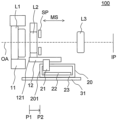
- FIG. 1 is a cross-sectional view of a lens device according to a first embodiment.
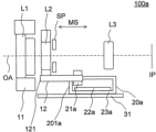
- FIG. 11 is a cross-sectional view of a lens device according to a second embodiment.
- FIG. 11 is a cross-sectional view of a lens device according to a third embodiment.
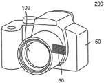
- FIG. 2 is a schematic diagram of an imaging device in each embodiment.
- Fig. 1 is a cross-sectional view of the lens device 100.
- the left side is the object side
- the right side is the image side.
- Fig. 1 shows only configurations that are directly related to the description of this embodiment, and configurations that are not directly related to the description of this embodiment are omitted.
- the spacing between adjacent lens groups in the multiple lens groups changes.
- the second lens group L2 moves in a direction along the optical axis OA (optical axis direction) with a movement stroke MS indicated by the arrow in FIG. 1.
- the first lens group L1 does not move when zooming. That is, the total lens length (the length on the optical axis from the lens surface closest to the object to the lens surface closest to the image of the multiple lens groups constituting the imaging optical system plus the back focus) does not change (total length is fixed).
- the lens device 100 has a diaphragm (aperture diaphragm) SP that moves with the second lens group L2, but is not limited to this.
- the first holding frame (first holding portion) 11 holds the first lens group L1.
- the second holding frame (second holding portion) 12 holds the second lens group L2 and moves together with the second lens group L2 in the optical axis direction. In the radial direction, the second holding frame 12 is smaller than the first holding frame 11.
- the voice coil motor (drive portion) 20 is connected to the second holding frame 12 and is configured to be able to transmit a driving force to the second holding frame 12, thereby driving the second holding frame 12 in the optical axis direction.
- the lens device 100 is capable of electric zoom, and the voice coil motor 20 drives the second holding frame 12 by control based on a user's operation or a user's instruction.
- the voice coil motor 20 has a coil 21, a magnet 22, and a yoke 23.
- the coil 21 is integral with the second holding frame 12.
- the magnet 22 and the yoke 23 are provided in the lens barrel 31 and form a magnetic field to move the coil 21.
- the coil 21, magnet 22, and yoke 23 In the lens device 100, to drive the second lens group L2 with the voice coil motor 20, the coil 21, magnet 22, and yoke 23 must be located near the second lens group L2. Because the magnet 22 and yoke 23 are large, there is a possibility that they may interfere (contact or collide) with, for example, the first lens group L1 or the first holding frame 11 during zooming. If the voice coil motor 20 is moved away from the optical axis OA (in the radial direction) to avoid interference, the lens device 100 will become larger.
- the positional relationship between the second holding frame 12 and the voice coil motor 20 in the optical axis direction is set so as to avoid interference between the first holding frame 11 and the voice coil motor 20. That is, in this embodiment, the front end 201 of the voice coil motor 20 (the first end of the voice coil motor 20 closest to the object) is disposed at a position P2 on the image side of the position P1 of the front end 121 of the second holding frame 12 (the second end of the second holding frame 12 closest to the object).
- the voice coil motor 20 is disposed outside the second retaining frame 12, which contributes to reducing the size of the lens device 100 in the radial direction, i.e., in the direction perpendicular to the optical axis OA (direction perpendicular to the optical axis).
- a lens device 100a according to a second embodiment of the present invention will be described with reference to Fig. 2.
- Fig. 2 is a cross-sectional view of the lens device 100a.
- the left side is the object side
- the right side is the image side.
- Fig. 2 like Fig. 1, only configurations directly related to the description of this embodiment are extracted and shown, and configurations not directly related to the description of this embodiment are omitted.
- Fig. 3 is a cross-sectional view of the lens device 100b.
- the left side is the object side
- the right side is the image side.
- Fig. 3 like Fig. 1, only the configuration directly related to the description of this embodiment is extracted and shown, and configurations not directly related to the description of this embodiment are omitted.
- the lens device 100b of this embodiment differs from the lens device 100 of the first embodiment, which has only one voice coil motor, in that it has a first voice coil motor (first driving member) 20b and a second voice coil motor (second driving member) 20c as driving units.
- this embodiment is not limited to a configuration having two voice coil motors, and can also be applied to a configuration having three or more voice coil motors.
- the two voice coil motors are a common motor, but this embodiment is not limited to this, and can also be applied to two motors with different characteristics or sizes. Note that other configurations and operations of the lens device 100b are common to the lens device 100, so their description will be omitted.
- position P3 of the third end (front end 201b) of the first voice coil motor 20b closest to the object and position P4 of the fourth end (front end 202c) of the second voice coil motor 20c closest to the object are different from each other. In other words, position P3 and position P4 do not coincide in the optical axis direction.
- FIG. 4 is a schematic diagram of the imaging device 200.
- a small lens device and imaging device can be provided.
Landscapes
- Physics & Mathematics (AREA)
- General Physics & Mathematics (AREA)
- Optics & Photonics (AREA)
- Engineering & Computer Science (AREA)
- General Engineering & Computer Science (AREA)
- Lens Barrels (AREA)
Priority Applications (2)
| Application Number | Priority Date | Filing Date | Title |
|---|---|---|---|
| CN202380085700.2A CN120359444A (zh) | 2022-12-16 | 2023-10-04 | 镜头设备和摄像设备 |
| US19/231,639 US20250298216A1 (en) | 2022-12-16 | 2025-06-09 | Lens apparatus and image pickup apparatus |
Applications Claiming Priority (2)
| Application Number | Priority Date | Filing Date | Title |
|---|---|---|---|
| JP2022200902A JP7608414B2 (ja) | 2022-12-16 | 2022-12-16 | レンズ装置および撮像装置 |
| JP2022-200902 | 2022-12-16 |
Related Child Applications (1)
| Application Number | Title | Priority Date | Filing Date |
|---|---|---|---|
| US19/231,639 Continuation US20250298216A1 (en) | 2022-12-16 | 2025-06-09 | Lens apparatus and image pickup apparatus |
Publications (1)
| Publication Number | Publication Date |
|---|---|
| WO2024127778A1 true WO2024127778A1 (ja) | 2024-06-20 |
Family
ID=91484792
Family Applications (1)
| Application Number | Title | Priority Date | Filing Date |
|---|---|---|---|
| PCT/JP2023/036140 Ceased WO2024127778A1 (ja) | 2022-12-16 | 2023-10-04 | レンズ装置および撮像装置 |
Country Status (4)
| Country | Link |
|---|---|
| US (1) | US20250298216A1 (https=) |
| JP (2) | JP7608414B2 (https=) |
| CN (1) | CN120359444A (https=) |
| WO (1) | WO2024127778A1 (https=) |
Citations (7)
| Publication number | Priority date | Publication date | Assignee | Title |
|---|---|---|---|---|
| JPH0829656A (ja) * | 1994-07-14 | 1996-02-02 | Konica Corp | レンズ鏡胴 |
| JPH08234092A (ja) * | 1995-02-24 | 1996-09-13 | Sony Corp | 電磁駆動装置及び電磁駆動装置を用いたズーム制御装置並びにフォーカス制御装置 |
| JP2000321475A (ja) * | 1999-05-13 | 2000-11-24 | Sony Corp | 光学駆動装置 |
| KR100866769B1 (ko) * | 2007-03-09 | 2008-11-04 | 성우전자 주식회사 | 휴대폰용 카메라의 자동초점조절장치 |
| WO2022024953A1 (ja) * | 2020-07-30 | 2022-02-03 | 富士フイルム株式会社 | レンズ鏡胴 |
| WO2022035192A1 (ko) * | 2020-08-11 | 2022-02-17 | 엘지이노텍 주식회사 | 카메라 엑추에이터 및 이를 포함하는 카메라 장치 |
| JP2022549097A (ja) * | 2019-09-16 | 2022-11-24 | エルジー イノテック カンパニー リミテッド | カメラモジュール |
-
2022
- 2022-12-16 JP JP2022200902A patent/JP7608414B2/ja active Active
-
2023
- 2023-10-04 CN CN202380085700.2A patent/CN120359444A/zh active Pending
- 2023-10-04 WO PCT/JP2023/036140 patent/WO2024127778A1/ja not_active Ceased
-
2024
- 2024-12-05 JP JP2024211993A patent/JP2025023282A/ja active Pending
-
2025
- 2025-06-09 US US19/231,639 patent/US20250298216A1/en active Pending
Patent Citations (7)
| Publication number | Priority date | Publication date | Assignee | Title |
|---|---|---|---|---|
| JPH0829656A (ja) * | 1994-07-14 | 1996-02-02 | Konica Corp | レンズ鏡胴 |
| JPH08234092A (ja) * | 1995-02-24 | 1996-09-13 | Sony Corp | 電磁駆動装置及び電磁駆動装置を用いたズーム制御装置並びにフォーカス制御装置 |
| JP2000321475A (ja) * | 1999-05-13 | 2000-11-24 | Sony Corp | 光学駆動装置 |
| KR100866769B1 (ko) * | 2007-03-09 | 2008-11-04 | 성우전자 주식회사 | 휴대폰용 카메라의 자동초점조절장치 |
| JP2022549097A (ja) * | 2019-09-16 | 2022-11-24 | エルジー イノテック カンパニー リミテッド | カメラモジュール |
| WO2022024953A1 (ja) * | 2020-07-30 | 2022-02-03 | 富士フイルム株式会社 | レンズ鏡胴 |
| WO2022035192A1 (ko) * | 2020-08-11 | 2022-02-17 | 엘지이노텍 주식회사 | 카메라 엑추에이터 및 이를 포함하는 카메라 장치 |
Also Published As
| Publication number | Publication date |
|---|---|
| JP7608414B2 (ja) | 2025-01-06 |
| JP2025023282A (ja) | 2025-02-14 |
| JP2024086039A (ja) | 2024-06-27 |
| CN120359444A (zh) | 2025-07-22 |
| US20250298216A1 (en) | 2025-09-25 |
Similar Documents
| Publication | Publication Date | Title |
|---|---|---|
| EP1582900B1 (en) | Optical apparatus | |
| JP7852588B2 (ja) | レンズ鏡筒及び撮像装置 | |
| JP5866487B2 (ja) | レンズユニット、及び撮像装置 | |
| JP7722514B2 (ja) | レンズ鏡筒及び撮像装置 | |
| US10855898B2 (en) | Lens apparatus and imaging system including the same | |
| JP7567994B2 (ja) | レンズ鏡筒及び撮像装置 | |
| JP2012053142A (ja) | レンズ鏡筒およびそれを有する光学機器 | |
| TWI418844B (zh) | 可變焦攝影模組 | |
| JP6537268B2 (ja) | レンズ駆動装置、及び光学機器 | |
| JP7608414B2 (ja) | レンズ装置および撮像装置 | |
| US20050286141A1 (en) | Lens barrel and photographing apparatus incorporating the same | |
| JP2002107598A (ja) | 沈胴式レンズ鏡筒及びこれを用いた光学機器 | |
| JP5867994B2 (ja) | レンズ鏡筒及び光学機器 | |
| US11256071B2 (en) | Lens apparatus and imaging system including the same | |
| JP2023141533A (ja) | 駆動装置及び光学装置 | |
| JP2002341226A (ja) | レンズ制御装置 | |
| US20230292006A1 (en) | Optical apparatus and image pickup apparatus having the same | |
| JP2001033683A (ja) | ズームレンズ装置 | |
| JP2007108540A (ja) | 撮像装置 | |
| JP2007086159A (ja) | 撮像装置 | |
| JP2007086158A (ja) | 撮像装置 | |
| JPH0836125A (ja) | 光学部材の駆動装置 | |
| JP2010122446A (ja) | レンズ鏡筒 | |
| JPH11109204A (ja) | レンズ鏡筒およびカメラ |
Legal Events
| Date | Code | Title | Description |
|---|---|---|---|
| 121 | Ep: the epo has been informed by wipo that ep was designated in this application |
Ref document number: 23903077 Country of ref document: EP Kind code of ref document: A1 |
|
| WWE | Wipo information: entry into national phase |
Ref document number: 202380085700.2 Country of ref document: CN |
|
| NENP | Non-entry into the national phase |
Ref country code: DE |
|
| WWP | Wipo information: published in national office |
Ref document number: 202380085700.2 Country of ref document: CN |
|
| 122 | Ep: pct application non-entry in european phase |
Ref document number: 23903077 Country of ref document: EP Kind code of ref document: A1 |