WO2024127464A1 - 電動機およびガスケット - Google Patents
電動機およびガスケット Download PDFInfo
- Publication number
- WO2024127464A1 WO2024127464A1 PCT/JP2022/045681 JP2022045681W WO2024127464A1 WO 2024127464 A1 WO2024127464 A1 WO 2024127464A1 JP 2022045681 W JP2022045681 W JP 2022045681W WO 2024127464 A1 WO2024127464 A1 WO 2024127464A1
- Authority
- WO
- WIPO (PCT)
- Prior art keywords
- gasket
- hole
- recess
- fastener
- electric motor
- Prior art date
- Legal status (The legal status is an assumption and is not a legal conclusion. Google has not performed a legal analysis and makes no representation as to the accuracy of the status listed.)
- Ceased
Links
Images






Classifications
-
- H—ELECTRICITY
- H02—GENERATION; CONVERSION OR DISTRIBUTION OF ELECTRIC POWER
- H02K—DYNAMO-ELECTRIC MACHINES
- H02K5/00—Casings; Enclosures; Supports
- H02K5/04—Casings or enclosures characterised by the shape, form or construction thereof
- H02K5/10—Casings or enclosures characterised by the shape, form or construction thereof with arrangements for protection from ingress, e.g. water or fingers
Definitions
- This disclosure relates to electric motors and gaskets.
- Electric motors are sometimes used in harsh environments.
- the electric motors of machine tools are used in environments where cutting fluid and the like splashes about. If the splashed cutting fluid seeps into the inside of the motor, it will cause it to malfunction. For this reason, gaskets are placed between the components that make up the motor (for example, Patent Document 1).
- the electric motor disclosed herein comprises a first member having a recess-forming surface on which a recess is formed, a gasket having a bead and arranged so that the bead contacts the portion of the recess-forming surface other than the recess, and a second member that sandwiches the gasket together with the first member.
- the gasket disclosed herein has a bead and is disposed between a first member having a recess-forming surface on which a recess is formed, and a second member, and the bead contacts the portion of the recess-forming surface other than the recess.
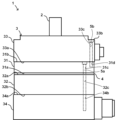
- FIG. 2 is a front view of an example of an electric motor.
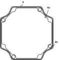
- FIG. 2 is a plan view of an example of a gasket.
- FIG. 3 is a partially enlarged view of FIG. 2 .
- FIG. 4 is a cross-sectional view taken along the line IV-IV in FIG. 3 .
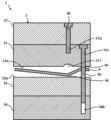
- FIG. 13 is a diagram for explaining an example of an arrangement of recesses and beads.
- FIG. 13A and 13B are diagrams for explaining other examples of the arrangement of the recesses and beads.
- FIG. FIG. 11 is a diagram for explaining an electric motor according to a second embodiment.
- FIG. FIG. 11 is a diagram showing another example of a gasket.
- FIG. 13 is a diagram showing another example of a gasket.
- 11A and 11B are diagrams showing an example of a manner in which the first member and the fourth member are fixed to each other;
- First Embodiment 1 is a front view of an example of an electric motor.
- the electric motor 1 is, for example, an electric motor used in a machine tool.
- the electric motor 1 is, for example, a servo motor or a spindle motor.
- the electric motor 1 comprises a rotor 2 and a stator 3.
- the rotor 2 is a member that rotates when it receives magnetic force from the stator 3.
- the stator 3 is a member that generates a magnetic force that rotates the rotor 2.
- the stator 3 includes a first member 31, a second member 32, a gasket 4, a third member 33, and a fourth member 34.
- the first member 31 is, for example, one of the members that constitute the housing of the electric motor 1.
- the first member 31 has a surface 31a that contacts the gasket 4 and a surface 31b that contacts the third member 33.
- the surface 31a that contacts the gasket 4 and the surface 31b that contacts the third member 33 are flat surfaces.
- a through hole 31c is formed between the surface 31b in contact with the third member 33 and the surface 31a in contact with the gasket 4.
- the through hole 31c is a hole into which the first fastener 5a is inserted.
- the through hole 31c is formed, for example, at a position slightly away from the side surface of the first member 31.
- the through hole 31c includes a countersink and a through hole.
- the countersunk hole is a hole into which the head of the first fastener 5a is housed.
- the through hole is a hole into which the threaded portion of the first fastener 5a is inserted.
- the through hole extends from the bottom surface of the countersunk hole toward the surface 31a that contacts the gasket 4.
- the through hole is a hole that penetrates between the bottom surface of the countersunk hole and the surface 31a that contacts the gasket 4.
- a blind hole 31d is formed in the surface 31b that contacts the third member 33, into which the second fastener 5b described below is inserted.
- the blind hole 31d is formed between the side surface of the first member 31 and the through hole 31c into which the first fastener 5a is inserted.
- the blind hole 31d is, for example, a screw hole.
- a screw hole is a hole that has been tapped.
- the first member 31 is manufactured, for example, by die casting.
- the first member 31 is, for example, aluminum die casting.
- the second member 32 is, for example, the core of the stator 3.
- the second member 32 is, for example, formed by stacking multiple electromagnetic steel sheets.
- the second member 32 has a surface 32a that contacts the gasket 4 and a surface 32b that contacts the fourth member 34.
- the surface 32a that contacts the gasket 4 and the surface 32b that contacts the fourth member 34 are flat surfaces.
- a through hole 32c is formed between the surface 32a in contact with the gasket 4 and the surface 32b in contact with the fourth member 34.
- the through hole 32c is a hole into which the first fastener 5a is inserted.
- the through hole 32c is, for example, a through hole. Note that when the second member 32 is an electromagnetic steel plate, the through hole 32c is drilled by pressing before stacking.
- the gasket 4 is a member for increasing the airtightness and liquidtightness between the first member 31 and the second member 32. That is, the gasket 4 is a member for preventing foreign matter such as cutting fluid from entering the inside of the electric motor 1 from between the first member 31 and the second member 32.
- the gasket 4 is made of, for example, metal. At least one surface of the gasket 4 may be coated with rubber. That is, the gasket 4 may be a gasket in which a metal layer is sandwiched between rubber layers.
- the gasket 4 may also be made of rubber.
- FIG. 2 is a plan view of an example of a gasket 4.
- the outer shape of the gasket 4 corresponds to the outer shapes of the first member 31 and the second member 32.
- the gasket 4 is formed in an annular shape. In other words, a through hole 4a is formed in the center of the gasket 4.
- the gasket 4 also has a number of small-diameter through holes 4b formed therein.
- the small-diameter through holes 4b are holes for passing the first fastener 5a through, or positioning holes for passing a positioning pin for positioning the first member 31 and the second member 32 relative to each other.
- FIG. 3 is a partially enlarged view of FIG. 2.
- the gasket 4 has a bead 4c.
- the bead 4c is a protruding portion provided on the gasket 4.
- the bead 4c is the portion that applies the greatest pressure to the first member 31 and the second member 32 when the gasket 4 is sandwiched between the first member 31 and the second member 32.
- the bead 4c is provided in a circular ring shape along the outer shape of the gasket 4.
- FIG. 4 is a cross-sectional view taken along line IV-IV in FIG. 3.
- the cross section of the gasket 4 has a shape in which a plate-like member is bent at one or more positions.
- the shape of the gasket 4 is a shape in which a plate-like member is bent at two positions.
- the bead 4c is formed, for example, by press working.
- both sides of the gasket 4 are coated with rubber 4d.
- both sides of the gasket 4 have a rubber layer. Note that only one side of the gasket 4 may be coated with rubber 4d.
- the third member 33 is, for example, one of the members that constitute the housing of the electric motor 1.
- the third member 33 has a surface 33a that contacts the first member 31.
- the third member 33 also has a surface 33b located on the opposite side to the surface 33a that contacts the first member 31.
- the surface 33a that contacts the first member 31 is a flat surface.
- the surface 33b located on the opposite side to the surface 33a that contacts the first member 31 may also be a flat surface.
- a through hole 33c is formed between the surface 33a in contact with the first member 31 and the surface 33b located on the opposite side of the surface 33a in contact with the first member 31.
- the through hole 33c is a hole into which the second fastener 5b is inserted.
- the through hole 33c is formed near the side surface of the third member 33. In other words, the second fastener 5b is positioned near the side surface of the third member 33.
- the third member 33 is fixed to the first member 31 by the second fastener 5b.
- the through hole 33c includes a countersunk hole and a through hole.
- the countersunk hole is a hole into which the head of the second fastener 5b is housed.
- the through hole is a hole into which the threaded portion of the second fastener 5b is inserted.
- the through hole extends from the bottom surface of the countersunk hole toward the surface 33a that contacts the first member 31.
- the through hole is a hole that penetrates between the bottom surface of the countersunk hole and the surface 33a that contacts the first member 31.
- the third member 33 is made of, for example, iron casting.
- the Young's modulus of the material constituting the third member 33 is greater than the Young's modulus of the material constituting the first member 31. In other words, the Young's modulus of the material constituting the first member 31 is less than the Young's modulus of the material constituting the third member 33.
- the rigidity of the third member 33 may be greater than the rigidity of the first member 31.
- the Young's modulus is also called Young's modulus.
- the fourth member 34 is, for example, one of the members that constitute the housing of the electric motor 1.
- the fourth member 34 has a surface 34a that contacts the second member 32.
- the surface 34a that contacts the second member 32 is a flat surface.
- a blind hole 34b into which the first fastener 5a is inserted is formed on the surface 34a that contacts the second member 32.
- the blind hole 34b is, for example, a screw hole.
- the fourth member 34 is manufactured, for example, by die casting.
- the fourth member 34 is, for example, aluminum die casting.
- FIG. 5 is a diagram for explaining an example of the arrangement of the recesses and beads 4c.
- the gasket 4 shown in FIG. 5 is a cross section of the gasket 4 taken along the line IV-IV in FIG. 3. That is, in FIG. 5, the right side shows the outside of the electric motor 1, and the left side shows the inside of the electric motor 1. Similarly, in FIG. 6 to FIG. 11, which will be described later, the right side shows the outside of the electric motor 1, and the left side shows the inside of the electric motor 1.
- the first fastener 5a is inserted into the through hole 31c of the first member 31, passes through the through hole 4b of the gasket 4 and the through hole 32c of the second member 32, and is inserted into the blind hole 34b. That is, the first member 31 and the fourth member 34 are fixed to each other by the first fastener 5a.
- the gasket 4 is interposed between the first member 31 and the second member 32. That is, the second member 32 sandwiches the gasket 4 together with the first member 31.
- the first fastener 5a When the first fastener 5a is inserted into the blind hole 34b of the fourth member 34 and tightened, a compressive stress acts on the first member 31. In other words, the first member 31 receives a compressive force from the seat surface of the first fastener 5a and the second member 32.
- the third member 33 receives a compressive force from the seat surface of the second fastener 5b and the first member 31.
- the first member 31 is pulled by the second fastener 5b.
- the second fastener 5b When the second fastener 5b is inserted into the blind hole 31d of the first member 31 and tightened, the first member 31 is pulled by the second fastener 5b.
- the first member 31 is pulled upward.
- the first member 31 is deformed by the second fastener 5b pulling the first member 31, particularly the area around the blind hole 31d.
- a recess 311 is formed in the surface 31a that contacts the gasket 4.
- the surface 31a of the first member 31 that contacts the gasket 4 is referred to as the recess-forming surface.
- the recess 311 is formed around the portion of the recess-forming surface 31a that intersects with the central axis of the second fastener 5b.
- the recess 311 is formed at a position on the recess forming surface 31a adjacent to the side surface.
- the bead 4c of the gasket 4 is formed so as to contact the portion of the recess-forming surface 31a other than the recess 311.
- the gasket 4 is positioned so that the bead 4c contacts the portion of the recess-forming surface 31a other than the recess 311.
- one of the two beads 4c formed on the gasket 4 is arranged so as to contact a flat surface other than the portion of the recess-forming surface 31a where the recess 311 is formed. Also, the other of the two beads 4c formed on the gasket 4 is arranged so as to contact a flat surface of the second member 32.
- the bead 4c elastically deforms when it receives forces from the first member 31 and the second member 32.
- the gasket 4 exerts an elastic force on the first member 31 and the second member 32, preventing a gap from being formed between the first member 31 and the second member 32.
- the gasket 4 may have a portion that undergoes plastic deformation when the first fastener 5a is tightened and sandwiched between the first member 31 and the second member 32.
- the portions of the gasket 4 other than the bead 4c may also be in contact with the first member 31 and the second member 32.
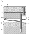
- FIG. 6 is a diagram showing a comparative example of the electric motor 1 of the first embodiment.
- the bead 4c when the bead 4c is disposed at a position corresponding to the recess 311, a part of the bead 4c enters the recess 311. In other words, the bead 4c does not contact the recess forming surface 31a. As a result, a gap is formed between the first member 31 and the second member 32. Or, even if no gap is formed, it is no longer possible to ensure sufficient airtightness and liquid tightness between the first member 31 and the second member 32.
- the first member 31 is pulled by the second fastener 5b arranged near the side surfaces of the first member 31 and the third member 33, and thus a recess 311 is formed near the side surface of the first member 31.
- the recess 311 may be formed not only near the side surface but also at a position closer to the center of the first member 31.
- FIG. 7 is a diagram for explaining another example of the arrangement of the recess 311 and the gasket 4.
- the first member 31 and the fourth member 34 are fixed to each other by the first fastener 5a.
- the through hole 31c into which the first fastener 5a is inserted is formed, for example, at a position adjacent to the side surface of the first member 31.
- the blind hole 31d into which the second fastener 5b is inserted is formed at a position farther from the side surface than the hole into which the first fastener 5a is inserted.
- the through hole 31c into which the first fastener 5a is inserted is formed between the blind hole 31d into which the second fastener 5b is inserted and the side surface.
- the first fastener 5a When the first fastener 5a is inserted into the blind hole 34b of the fourth member 34 and tightened, a compressive stress acts on the first member 31. In other words, the first member 31 receives a compressive force from the seat surface of the first fastener 5a and the second member 32.
- the first member 31, particularly the area around the blind hole 31d, is pulled by the second fastener 5b, causing the first member 31 to deform.
- the second fastener 5b pulls the first member 31, particularly the area around the blind hole 31d, forming a recess 311 in the recess-forming surface 31a.
- the recess 311 is formed in the portion of the recess-forming surface 31a that intersects with the central axis of the second fastener 5b.
- the recess 311 is formed at a position slightly away from the side of the recess forming surface 31a.
- the bead 4c of the gasket 4 is formed so as to contact the portion of the recess-forming surface 31a other than the recess 311.
- the gasket 4 is positioned so that the bead 4c contacts the portion of the recess-forming surface 31a other than the recess 311.
- one of the two beads 4c formed on the gasket 4 is positioned so as to contact a flat surface other than the portion of the recess-forming surface 31a where the recess 311 is formed. Also, the other of the two beads 4c formed on the gasket 4 is positioned so as to contact a flat surface of the second member 32.
- the bead 4c elastically deforms when it receives forces from the first member 31 and the second member 32.
- the gasket 4 exerts an elastic force on the first member 31 and the second member 32, preventing a gap from being formed between the first member 31 and the second member 32.
- FIG. 8 is a diagram showing a comparative example.
- the comparative example when the bead 4c is formed at a position corresponding to the recess 311, a part of the bead 4c enters the recess 311. In other words, the bead 4c does not contact the recess forming surface 31a. As a result, a gap is formed between the first member 31 and the second member 32. Or, even if no gap is formed, it is no longer possible to ensure sufficient airtightness and liquid tightness between the first member 31 and the second member 32.
- Second Embodiment 9 is a diagram for explaining the electric motor 1 of the second embodiment.
- the electric motor 1 of the first embodiment and the electric motor 1 of the second embodiment differ in whether the recess 311 is formed by deformation or not. That is, in the electric motor 1 of the second embodiment, the recess 311 formed on the recess forming surface 31a of the first member 31 is not formed by pulling of a fastener.
- the cause of the recess 311 is, for example, a processing error.
- the bead 4c of the gasket 4 is formed so as to contact the portion of the recess-forming surface 31a other than the recess 311.
- the gasket 4 is positioned so that the bead 4c contacts the portion of the recess-forming surface 31a other than the recess 311.
- one of the two beads 4c formed on the gasket 4 is arranged so as to contact a flat surface of the recess-forming surface 31a other than the portion where the recess 311 is formed. Also, the other of the two beads 4c formed on the gasket 4 is arranged so as to contact a flat surface of the second member 32.
- the bead 4c elastically deforms when it receives forces from the first member 31 and the second member 32.
- the gasket 4 exerts an elastic force on the first member 31 and the second member 32, preventing a gap from being formed between the first member 31 and the second member 32.
- FIG. 10 is a diagram showing a comparative example of the electric motor 1 of the second embodiment.
- the bead 4c when the bead 4c is formed at a position corresponding to the recess 311, a part of the bead 4c enters the recess 311. In other words, the bead 4c does not contact the recess forming surface 31a. As a result, a gap is formed between the first member 31 and the second member 32. Or, even if no gap is formed, it is no longer possible to ensure sufficient airtightness and liquid tightness between the first member 31 and the second member 32.
- the cross-section of the gasket 4 is a shape in which a plate-shaped member is bent at one or more positions.
- the cross-sectional shape of the gasket 4 is not limited to this.
- FIG. 11 shows another example of the gasket 4.
- the cross section of the gasket 4 is a shape that combines a straight line and an arc.
- the bead 4c is formed in an arc shape.
- FIG. 12 shows another example of the gasket 4.
- the cross section of the gasket 4 is a shape in which a straight line and a U-shaped line are connected.
- the bead 4c is formed in a U-shape.
- the first fastener 5a inserted from the through hole 31c of the first member 31 is fastened into the blind hole 34b formed in the fourth member 34. This fixes the first member 31 and the fourth member 34 with the gasket 4 and the second member 32 sandwiched between them.
- the manner in which the first member 31 and the fourth member 34 are fixed is not limited to this.
- first member 31 and the fourth member 34 may be fixed together using the first fastener 5a, the third fastener, and a rod.
- FIG. 13 is a diagram showing an example of a fixing mode between the first member 31 and the fourth member 34.
- a through hole 31c is formed between the surface 31b that contacts the third member 33 and the surface 31a that contacts the gasket 4.
- the through hole 31c is a hole into which the first fastener 5a and a part of the rod 5d described later are inserted.
- the through hole 31c includes a countersink, a rod insertion hole, and a through hole.
- the countersunk hole is a hole into which the head of the first fastener 5a is housed.
- the rod insertion hole is a hole into which a portion of the rod 5d is inserted.
- the rod insertion hole is located opposite the countersunk hole.
- the through hole is a hole into which the threaded portion of the first fastener 5a is inserted.
- the through hole extends from the bottom surface of the countersunk hole toward the rod insertion hole. In other words, the through hole is a hole that penetrates between the bottom surface of the countersunk hole and the bottom surface of the rod insertion hole.
- a through hole 32c is formed between a surface 32a that contacts the gasket 4 and a surface 32b that contacts the fourth member 34.
- the through hole 32c is a hole through which the rod 5d is inserted.
- the through hole 32c is, for example, a through hole.
- the fourth member 34 has a surface 34c located on the opposite side of the surface 34a that contacts the second member 32.
- a through hole 34d is formed between the surface 34a that contacts the second member 32 and the surface 34c located on the opposite side of the surface 34a that contacts the second member 32.
- the through hole 34d is a hole into which the third fastener 5c and a part of the rod 5d are inserted.
- the through hole 34d includes a countersink, a rod insertion hole, and a through hole.
- the countersunk hole is a hole into which the head of the third fastener 5c is housed.
- the rod insertion hole is a hole into which a portion of the rod 5d is inserted.
- the rod insertion hole is located opposite the countersunk hole.
- the through hole is a hole into which the threaded portion of the third fastener 5c is inserted.
- the through hole extends from the bottom surface of the countersunk hole toward the rod insertion hole. In other words, the through hole is a hole that penetrates between the bottom surface of the countersunk hole and the bottom surface of the rod insertion hole.
- a rod 5d is inserted into the through hole 32c of the second member 32. Threaded holes are formed on both ends of the rod 5d.
- the first fastener 5a is inserted into the through hole 31c of the first member 31 and screwed into one of the screw holes of the rod 5d.
- the third fastener 5c is inserted into the through hole 34d of the fourth member 34 and screwed into the other screw hole of the rod 5d.
- the first member 31 and the fourth member 34 are fixed to each other by the first fastener 5a, the third fastener 5c, and the rod 5d.
- a gasket 4 is interposed between the first member 31 and the second member 32.
- FIG. 1, etc. an example (FIG. 1, etc.) has been described in which a blind hole 31d is formed between the side surface of the first member 31 and the through hole 31c into which the first fastener 5a is inserted
- FIG. 7 an example (FIG. 7) has been described in which a through hole 31c is formed between the blind hole 31d into which the second fastener 5b is inserted and the side surface of the first member 31.
- the positions of the through hole 31c and the blind hole 31d formed in the first member 31 are not limited to these.
- the through hole 31c and the blind hole 31d may be disposed near different side surfaces of the first member 31.
- the through hole 31c and the blind hole 31d may be disposed closer to each other or farther apart.
- the electric motor 1 includes a first member 31 having a recess-forming surface 31a on which a recess 311 is formed, a gasket 4 having a bead 4c and arranged so that the bead 4c contacts the portion of the recess-forming surface 31a other than the recess 311, and a second member 32 that sandwiches the gasket 4 together with the first member 31.
- the electric motor 1 can prevent foreign matter from entering the inside of the electric motor 1. As a result, the electric motor 1 can prevent malfunctions and improve the operating rate.
- the electric motor 1 further includes a third member 33 that is fixed to the first member 31 by a fastener, and the recess 311 is formed by the fastener pulling the first member 31. Therefore, even if deformation is caused by the fastener, the electric motor 1 can prevent foreign matter from entering the interior of the electric motor 1.
- the Young's modulus of the material constituting the first member 31 is smaller than the Young's modulus of the material constituting the third member 33. In other words, the first member 31 deforms more than the third member 33. Even in this case, the electric motor 1 can prevent foreign matter from entering the interior.
- At least one surface of the gasket 4 is coated with rubber 4d. This allows the motor 1 to more reliably prevent foreign matter from entering the interior.
- the gasket 4 is also made of metal.
- the gasket 4 has a moderate elasticity, and can more reliably prevent foreign matter from entering the inside of the electric motor 1.
- a gasket in which a metal layer is sandwiched between rubber layers has both waterproofing and heat dissipation properties.
- a gasket in which a metal layer is sandwiched between rubber layers can be processed into the desired shape of the gasket 4. Therefore, when the gasket 4 is a gasket in which a metal layer is sandwiched between rubber layers, it becomes easier for the designer to design the shape of the bead 4c.
- the gasket 4 also has a bead 4c, and is disposed between a first member 31 and a second member 32 having a recess-forming surface 31a on which a recess 311 is formed, and the bead 4c contacts the portion of the recess-forming surface 31a other than the recess 311. Therefore, the gasket 4 can prevent foreign matter from entering the inside of the electric motor 1 even if the surface of the member sandwiching the gasket 4 has a recess 311. As a result, the electric motor 1 can prevent malfunctions and improve its operating rate.
- Appendix [1] An electric motor comprising: a first member having a recess-forming surface on which a recess is formed; a gasket having a bead and arranged so that the bead contacts a portion of the recess-forming surface other than the recess; and a second member that sandwiches the gasket together with the first member.
- Appendix [2] The electric motor according to claim [1], further comprising a third member fixed to the first member by a fastener, wherein the recess is formed by the fastener pulling the first member.
- Appendix [3] The electric motor according to claim [2], wherein a Young's modulus of the material constituting the first member is smaller than a Young's modulus of the material constituting the third member.
- Appendix [4] The electric motor according to any one of appendices [1] to [3], wherein at least one surface of the gasket is coated with rubber.
- Appendix [5] The electric motor according to any one of appendices [1] to [4], wherein the gasket is made of metal.
- a gasket having a bead and disposed between a first member and a second member having a recess-forming surface on which a recess is formed, the bead being in contact with a portion of the recess-forming surface other than the recess.
Landscapes
- Engineering & Computer Science (AREA)
- Power Engineering (AREA)
- Motor Or Generator Frames (AREA)
- Gasket Seals (AREA)
Priority Applications (4)
| Application Number | Priority Date | Filing Date | Title |
|---|---|---|---|
| DE112022007747.6T DE112022007747T5 (de) | 2022-12-12 | 2022-12-12 | Elektromotor und dichtung |
| JP2024563783A JPWO2024127464A1 (https=) | 2022-12-12 | 2022-12-12 | |
| PCT/JP2022/045681 WO2024127464A1 (ja) | 2022-12-12 | 2022-12-12 | 電動機およびガスケット |
| CN202280102264.0A CN120303861A (zh) | 2022-12-12 | 2022-12-12 | 电动机和垫片 |
Applications Claiming Priority (1)
| Application Number | Priority Date | Filing Date | Title |
|---|---|---|---|
| PCT/JP2022/045681 WO2024127464A1 (ja) | 2022-12-12 | 2022-12-12 | 電動機およびガスケット |
Publications (1)
| Publication Number | Publication Date |
|---|---|
| WO2024127464A1 true WO2024127464A1 (ja) | 2024-06-20 |
Family
ID=91484536
Family Applications (1)
| Application Number | Title | Priority Date | Filing Date |
|---|---|---|---|
| PCT/JP2022/045681 Ceased WO2024127464A1 (ja) | 2022-12-12 | 2022-12-12 | 電動機およびガスケット |
Country Status (4)
| Country | Link |
|---|---|
| JP (1) | JPWO2024127464A1 (https=) |
| CN (1) | CN120303861A (https=) |
| DE (1) | DE112022007747T5 (https=) |
| WO (1) | WO2024127464A1 (https=) |
Citations (6)
| Publication number | Priority date | Publication date | Assignee | Title |
|---|---|---|---|---|
| JPH0550244U (ja) * | 1991-12-11 | 1993-07-02 | エヌオーケー株式会社 | ガスケット |
| JPH11141684A (ja) * | 1997-11-06 | 1999-05-25 | Nok Corp | ガスケットおよびその製造方法 |
| JP2011047508A (ja) * | 2009-08-28 | 2011-03-10 | Nok Corp | ガスケット |
| JP2016046913A (ja) * | 2014-08-22 | 2016-04-04 | 日本電産株式会社 | モータ |
| JP2022094617A (ja) * | 2020-12-15 | 2022-06-27 | マブチモーター株式会社 | モータユニットおよびモータユニットの製造方法 |
| WO2022244349A1 (ja) * | 2021-05-20 | 2022-11-24 | ファナック株式会社 | 電動機 |
-
2022
- 2022-12-12 JP JP2024563783A patent/JPWO2024127464A1/ja active Pending
- 2022-12-12 WO PCT/JP2022/045681 patent/WO2024127464A1/ja not_active Ceased
- 2022-12-12 DE DE112022007747.6T patent/DE112022007747T5/de active Pending
- 2022-12-12 CN CN202280102264.0A patent/CN120303861A/zh active Pending
Patent Citations (6)
| Publication number | Priority date | Publication date | Assignee | Title |
|---|---|---|---|---|
| JPH0550244U (ja) * | 1991-12-11 | 1993-07-02 | エヌオーケー株式会社 | ガスケット |
| JPH11141684A (ja) * | 1997-11-06 | 1999-05-25 | Nok Corp | ガスケットおよびその製造方法 |
| JP2011047508A (ja) * | 2009-08-28 | 2011-03-10 | Nok Corp | ガスケット |
| JP2016046913A (ja) * | 2014-08-22 | 2016-04-04 | 日本電産株式会社 | モータ |
| JP2022094617A (ja) * | 2020-12-15 | 2022-06-27 | マブチモーター株式会社 | モータユニットおよびモータユニットの製造方法 |
| WO2022244349A1 (ja) * | 2021-05-20 | 2022-11-24 | ファナック株式会社 | 電動機 |
Also Published As
| Publication number | Publication date |
|---|---|
| JPWO2024127464A1 (https=) | 2024-06-20 |
| CN120303861A (zh) | 2025-07-11 |
| DE112022007747T5 (de) | 2025-07-03 |
Similar Documents
| Publication | Publication Date | Title |
|---|---|---|
| EP2682632A2 (en) | Disc brake apparatus | |
| EP3511592B1 (en) | Vibration-damping device body and vibration-damping device | |
| WO2024127464A1 (ja) | 電動機およびガスケット | |
| JP4313748B2 (ja) | 少なくとも一つの肉厚な楔部材を含むシリンダヘッド用多層ガスケット | |
| JP4377434B2 (ja) | スタビライザブッシュ | |
| WO2019176475A1 (ja) | 電動圧縮機 | |
| JP7147194B2 (ja) | パワーコントロールユニット及びその取付構造 | |
| US20090302551A1 (en) | Flat seal with adhesively bonded or inserted functional element for internal combustion engine | |
| JP4631266B2 (ja) | シリンダヘッドガスケット | |
| JP2017132441A (ja) | 車両用筐体固定ユニット及び基板収容筐体 | |
| JP4685039B2 (ja) | 電力半導体装置 | |
| JP2007527816A (ja) | 自動車のホイールサスペンション用のラジアスアーム | |
| US12104670B2 (en) | Vibration-damping device | |
| JP2014185738A (ja) | 配管固定部材 | |
| WO2012017768A1 (ja) | シリンダヘッドガスケットおよびその製造方法 | |
| JP3675243B2 (ja) | 電子制御機器 | |
| JP4238202B2 (ja) | 肉厚部分を備えている鋼板を含むガスケット | |
| JP7609107B2 (ja) | 基板固定構造 | |
| JP2007077975A (ja) | 内燃機関 | |
| US20230332677A1 (en) | Torque converter cover to pilot assembly | |
| US20260040476A1 (en) | Component mounting structure | |
| JP7285753B2 (ja) | ガスケット | |
| JP4835981B2 (ja) | 画像形成装置 | |
| CN111696806B (zh) | 开关座体改良结构 | |
| CN119037078A (zh) | 一种集成组件 |
Legal Events
| Date | Code | Title | Description |
|---|---|---|---|
| 121 | Ep: the epo has been informed by wipo that ep was designated in this application |
Ref document number: 22968376 Country of ref document: EP Kind code of ref document: A1 |
|
| WWE | Wipo information: entry into national phase |
Ref document number: 2024563783 Country of ref document: JP |
|
| WWE | Wipo information: entry into national phase |
Ref document number: 112022007747 Country of ref document: DE |
|
| WWE | Wipo information: entry into national phase |
Ref document number: 202280102264.0 Country of ref document: CN |
|
| WWP | Wipo information: published in national office |
Ref document number: 112022007747 Country of ref document: DE |
|
| WWP | Wipo information: published in national office |
Ref document number: 202280102264.0 Country of ref document: CN |
|
| 122 | Ep: pct application non-entry in european phase |
Ref document number: 22968376 Country of ref document: EP Kind code of ref document: A1 |