WO2024121995A1 - 車両制御装置 - Google Patents
車両制御装置 Download PDFInfo
- Publication number
- WO2024121995A1 WO2024121995A1 PCT/JP2022/045167 JP2022045167W WO2024121995A1 WO 2024121995 A1 WO2024121995 A1 WO 2024121995A1 JP 2022045167 W JP2022045167 W JP 2022045167W WO 2024121995 A1 WO2024121995 A1 WO 2024121995A1
- Authority
- WO
- WIPO (PCT)
- Prior art keywords
- wave radar
- millimeter wave
- error
- control device
- vehicle control
- Prior art date
- Legal status (The legal status is an assumption and is not a legal conclusion. Google has not performed a legal analysis and makes no representation as to the accuracy of the status listed.)
- Ceased
Links
Images





Classifications
-
- G—PHYSICS
- G08—SIGNALLING
- G08G—TRAFFIC CONTROL SYSTEMS
- G08G1/00—Traffic control systems for road vehicles
- G08G1/16—Anti-collision systems
Definitions
- the present invention relates to a vehicle control device.
- Patent Document 1 discloses a technology in which two millimeter wave radars with different near-far characteristics are installed facing the same direction, and the two detection points are combined with weights determined based on which millimeter wave radar has the highest accuracy for the detection points of each millimeter wave radar, the number of times the radar was lost, etc., to be used as the fusion position.
- Patent Document 1 does not take into account the detection error of the millimeter wave radar, so there is a risk that the accuracy of the fusion position will decrease. In addition, since it is assumed that millimeter wave radars with different characteristics are installed facing the same direction, there is also an issue that the systems to which it can be applied are limited.
- the objective of the present invention is to provide a vehicle control device that can perform highly accurate and versatile sensing using only millimeter wave radar in driving assistance technology, by taking into account detection errors based on the principles of millimeter wave radar, while at the same time using an algorithm that calculates the fusion position of millimeter wave radar x millimeter wave radar that can be applied to any system with any millimeter wave radar characteristics or installation position/angle/height, and in any scene.
- the vehicle control device of the present invention is a vehicle control device that detects objects around a vehicle and controls the vehicle, and is characterized in that it has a first millimeter wave radar and a second millimeter wave radar installed at a position different from the first millimeter wave radar, and detects the object based on a first ranging position and a first measurement error of the object detected by the first millimeter wave radar and a second ranging position and a second measurement error of the object detected by the second millimeter wave radar.
- the present invention provides a vehicle control device that is capable of sensing the sides, rear, etc. with high accuracy and versatility using only millimeter wave radar.
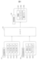
- FIG. 1 is a configuration explanatory diagram showing an example of a hardware configuration of a system including a controller (vehicle control device) according to a first embodiment of the present invention.
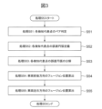
- 4 is a flowchart showing a process flow of a fusion program executed by a controller (vehicle control device) in the first embodiment of the present invention.
- 11 is a flowchart showing a detailed processing flow of step S5 in the first embodiment of the present invention.
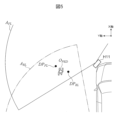
- 11 is an overhead view showing an example of an assumed scene for explaining a process S5 in the first embodiment of the present invention.
- FIG. 11 is an explanatory diagram of pair determination performed in process S51 in the first embodiment of the present invention.
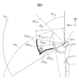
- FIG. 7 is an explanatory diagram of error circular arc calculation performed in step S52 in the first embodiment of the present invention.
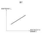
- FIG. 4 is a map showing an example of the relationship between a linear distance R to a detection representative point and an error circular angle ⁇ EA in the first embodiment of the present invention. 4 is a map showing an example of the relationship between the angle ⁇ DP between the direction of the detection representative point and the millimeter wave radar base axis, and the error arc angle ⁇ EA in the first embodiment of the present invention.
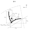
- 6 is an explanatory diagram of the decomposition of error arcs performed in step S53 in the first embodiment of the present invention.
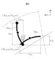
- 11A and 11B are explanatory diagrams of fusion position calculation on each coordinate axis performed in step S54 and step S55 in the first embodiment of the present invention.
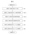
- 10 is a flowchart showing a detailed process flow of step S5 in the second embodiment of the present invention.
- 13 is an overhead view showing an example of an assumed scene for explaining a process S5 in the second embodiment of the present invention.
- FIG. 11 is an explanatory diagram of pair determination performed in process S51 in the second embodiment of the present invention.
- FIG. 11 is an explanatory diagram of a base error circular arc calculation performed in step S52-1 in the second embodiment of the present invention.
- FIG. 11 is an explanatory diagram of error circular arc calculation performed in step S52-2 in the second embodiment of the present invention.
- FIG. 11 is an explanatory diagram of an example of a base error circular adjustment gain G height depending on a difference in installation height of each millimeter wave radar in the second embodiment of the present invention.
- FIG. 11 is an explanatory diagram of an example of a base error arc adjustment gain GSN due to a difference in SNR between millimeter wave radars in the second embodiment of the present invention.
- FIG. 11 is an explanatory diagram of an example of a base error arc adjustment gain G ri based on a difference in laser reflection intensity between millimeter wave radars in the second embodiment of the present invention.
- 13 is an explanatory diagram of the decomposition of an error arc performed in step S53 in the second embodiment of the present invention.
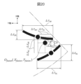
- FIG. 13 is an explanatory diagram of fusion position calculation on each coordinate axis performed in step S54 and step S55 in the second embodiment of the present invention.
- FIG. 11 is an explanatory diagram of fusion position calculation on each coordinate axis performed in step S54 and step S55 in the
- the vehicle coordinate system is set with the vehicle's longitudinal (length) direction as the X-axis, the vehicle's lateral (width) direction as the Y-axis, the center point of the vehicle's front axle as the origin, and angles in the forward direction of the vehicle as 0 degrees, with counterclockwise angles being positive.
- FIG. 1 is a configuration explanatory diagram showing an example of the hardware configuration of a system including a controller (vehicle control device) in a first embodiment of the present invention.
- This system is a system for executing driving assistance control that detects objects around a vehicle and controls the vehicle.
- This system includes an external information acquisition unit H1 that includes an FL millimeter wave radar H11 that detects the left front, an FR millimeter wave radar H12 that detects the right front, an RL millimeter wave radar H13 that detects the left rear, and an RR millimeter wave radar H14 that detects the right rear, and a vehicle information acquisition unit H2 including a speed sensor H21, a steering angle sensor H22, a yaw rate sensor H23, etc.; a controller H3 that calculates fusion target information that integrates the detection results of each millimeter wave radar based on the external environment information from the external environment information acquisition unit H1 and the host vehicle information acquired by the host vehicle information acquisition unit H2, and outputs, as necessary, a warning command to the driver to avoid a collision with the fusion target, a brake command to stop the host vehicle, a steering command to turn the host vehicle, etc.;
- the vehicle control unit H4 is composed of an alarm device H41 which performs alarm control based on an alarm command calculated by the controller
- Each millimeter wave radar constituting the external environment information acquisition unit H1 is installed at a different position on the vehicle.
- the FL millimeter wave radar H11 is installed at the front left of the vehicle
- the FR millimeter wave radar H12 is installed at the front right of the vehicle
- the RL millimeter wave radar H13 is installed at the rear left of the vehicle
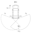
- the RR millimeter wave radar H14 is installed at the rear right of the vehicle (see also Figures 4, 12, etc.).
- the millimeter wave radars constituting the external environment information acquisition unit H1 may have the same characteristics or different characteristics.
- Figure 2 shows the processing flow of the fusion program executed by the controller H3.
- the detection point information (X position, Y position, radar reflection intensity, etc.) of each millimeter wave radar is obtained from the external information acquisition unit H1.
- process S2 the time axes of the detection point information of each millimeter wave radar acquired in process S1 are unified, and the detection point information of each millimeter wave radar at the same time is calculated.
- process S3 the position coordinates of the detection point information from each millimeter wave radar at the same time obtained in process S2 are unified.
- process S4 the detection points detected by the same millimeter wave radar are grouped from the detection point information of each millimeter wave radar at the same time and coordinates obtained in process S3. This is a process in which, for example, detection points that are close to each other are regarded as the same target and made into a single detection representative point.
- process S5 the representative points detected by different millimeter wave radars are fused together for each representative point group detected by each millimeter wave radar obtained in process S4, and the final fusion target information is calculated.
- FIG. 3 shows the detailed processing flow of step S5.
- step S51 pairs of detection representative points to be fused are scanned. For example, detection representative points that are close to each other are determined to be a pair.
- an error arc is defined for each of the two detection representative points (pairs) obtained in process S51.
- An error arc is a distribution of the existence probability for a detection point, and generally has a shape that spreads in the direction perpendicular to the laser irradiation according to the detection principle of millimeter wave radar.
- an error arc is a distribution of measurement errors in the direction perpendicular to the laser irradiation (perpendicular to the laser irradiation direction) for a detection point that is the ranging position of a target detected by a millimeter wave radar.
- step S53 the error arc of each detection representative point is decomposed into error amounts in the X and Y directions.
- the decomposed error amounts can be referred to as the expected error in the vehicle coordinate system of each detection representative point (the ranging position of the target detected by each millimeter wave radar).
- step S54 the fusion position in the X direction of each detection representative point is calculated. This is calculated so that it is located between each (paired) detection representative point based on the ratio of the error amount in the X direction of each detection representative point (assumed error in the vehicle coordinate system).
- step S55 the fusion position in the Y direction of each detection representative point is calculated. This is calculated so that it is located between each (paired) detection representative point based on the ratio of the error amount in the Y direction of each detection representative point (assumed error in the vehicle coordinate system).
- FIG. 4 shows an example of a hypothetical scene for explaining the process S5 in more detail.
- the process will be explained for a case where a pedestrian target O PED exists in an area where the detection area A FL of the FL millimeter wave radar H11 and the detection area A RL of the RL millimeter wave radar H13 overlap.
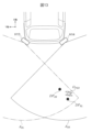
- FIG. 5 is an explanatory diagram of the pair determination performed in the process S51. If the position coordinates ( XFL , YFL) of the detection representative point DPFL of the FL millimeter-wave radar H11 and the position coordinates ( XRL , YRL ) of the detection representative point DPRL of the RL millimeter-wave radar H13 obtained in process S4 satisfy the following determination formula 1, the pair determination is established.
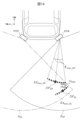
- FIG. 6 shows an explanatory diagram of the error arc calculation performed in step S52. However, to prevent the diagram from becoming too complicated, only the information that is the process for defining the error arc is shown for the FL millimeter wave radar H11.
- the error arc EA FL of the FL millimeter wave radar H11 has a shape that spreads out like a sector with an error arc angle ⁇ EA_FL centered on the detection representative point DP FL .
- the detection representative point DP FL corresponds to the distance measurement position of the pedestrian target O PED by the FL millimeter wave radar H11
- the arc with the error arc angle ⁇ EA_FL corresponds to the measurement error (perpendicular to the laser irradiation direction) of the pedestrian target O PED by the FL millimeter wave radar H11.
- the error arc angle ⁇ EA_FL is set in a three-dimensional map with the linear distance R FL to the detection representative point DP FL and the angle ⁇ DP_FL formed by the direction of the detection representative point DP FL and the millimeter wave radar base axis BL FL as arguments.
- the error circular angle ⁇ EA is set to be larger as the linear distance R to the detection representative point becomes larger. This setting takes into consideration the characteristics of millimeter wave radar, in which the detection accuracy decreases the further away from the millimeter wave radar.
- the angle ⁇ DP between the direction of the detection representative point and the millimeter-wave radar base axis is set so that the error arc angle ⁇ EA is larger for detection representative points that are located outside the FOV (sensible field of view). This setting takes into consideration the characteristics of millimeter-wave radar, in which the detection accuracy decreases the further outside the FOV of the millimeter-wave radar.
- the relationship of the error arc angle ⁇ EA in Figures 7 and 8 is merely an example, and can be set arbitrarily as long as the gist of this embodiment can be reproduced.
- This map may be published as catalog values by millimeter wave radar suppliers in some cases, but designers may adapt it in advance through actual vehicle testing, etc.
- each millimeter wave radar can have its own unique map, it is possible to accommodate not only fusion between the same millimeter wave radars, but also fusion between millimeter wave radars from different suppliers, for example.
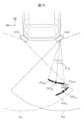
- FIG. 9 shows an explanatory diagram of the decomposition of error arcs performed in the process S53. However, to prevent the diagram from becoming too complicated, only the information that is part of the process of decomposing error arcs related to the FL millimeter wave radar H11 is shown.
- the error arc EA FL of the FL millimeter-wave radar H11 defined in process S52 is decomposed into the X-axis direction and the Y-axis direction by coordinate conversion based on Equation 2, and the XY coordinates (X FL_CCW , Y FL_CCW ) of the counterclockwise end point and the XY coordinates (X FL_CW , Y FL_CW ) of the clockwise end point are calculated.
- the X-axis direction error amount ⁇ X FL and the Y-axis direction error amount ⁇ Y FL are calculated from the XY coordinates of each end point based on Equation 3.
- the X-axis direction error amount ⁇ X FL is an assumed error in the X-axis direction in the vehicle coordinate system of the FL millimeter-wave radar H11 (detection representative point DP FL by the FL millimeter-wave radar H11), and the Y-axis direction error amount ⁇ Y FL is an assumed error in the Y-axis direction in the vehicle coordinate system of the FL millimeter-wave radar H11 (detection representative point DP FL by the FL millimeter-wave radar H11).
- the XY coordinates (X RL_CCW , Y RL_CCW ) of the counterclockwise end point of the error arc EA RL and the XY coordinates (X RL_CW , Y RL_CW ) of the clockwise end point of the error arc EA RL are calculated by coordinate conversion based on Equation 4, and the X-axis direction error amount ⁇ X RL and the Y-axis direction error amount ⁇ Y RL are calculated based on Equation 5.
- the X-axis direction error amount ⁇ X RL is the assumed error in the X-axis direction in the vehicle coordinate system of the RL millimeter-wave radar H13 (detection representative point DP RL by the RL millimeter-wave radar H13), and the Y-axis direction error amount ⁇ Y RL is the assumed error in the Y-axis direction in the vehicle coordinate system of the RL millimeter-wave radar H13 (detection representative point DP RL by the RL millimeter-wave radar H13).
- the X-axis fusion position Xfusion is calculated based on the formula 6.
- the weight wX_FL is a parameter that determines the ratio between two detection representative points, and is determined by the ratio of the error amount in the X-axis direction (assumed error in the vehicle coordinate system) of each detection representative point obtained in the process S53 as shown in the formula 7.
- step S55 the Y-axis direction fusion position Y fusion is calculated similarly based on Equations 8 and 9.
- step S5 This completes step S5, and the final fusion position O fusion is set.
- the fusion position based on the ratio of the error amount (assumed error in the vehicle coordinate system), it is possible to estimate a position with a higher probability of existence while taking into account the error directivity of the millimeter wave radar.
- the fusion position based on the ratio of the error amount (assumed error in the vehicle coordinate system)
- an individual error arc map for each millimeter wave radar it can be used for fusion between millimeter wave radars from different suppliers, for example, and can be applied with high versatility.
- the error arc calculated in step S52 of Example 1 is defined as a base error arc, and the size of the base error arc (corresponding to the measurement error) is adjusted based on the installation height of each millimeter wave radar, the S/N ratio (signal-to-noise ratio), the laser reflection intensity, etc., to define the error arc that serves as input information for step S53.
- the process is described using an example of a scene in which fusion is performed by RL millimeter wave radar H13 and RR millimeter wave radar H14. Note that the same parts and processes in Example 2 and Example 1 are given the same reference numerals, and their description will not be repeated.
- FIG. 11 shows a detailed flowchart of process S5 in Example 2.
- step S51 the detected representative points are paired, and step S51 is the same as in Example 1.
- a base error arc is defined for each of the two detection representative points (pairs) obtained in process S51.
- the base error arc is synonymous with the error arc defined in process S52 in the first embodiment, so a description of it will be omitted.
- process S52-2 the size of each base error arc obtained in process S52-1 is adjusted by a gain calculated based on the installation height, signal-to-noise ratio, laser reflection intensity, etc. of each millimeter wave radar.
- FIG. 12 shows an explanatory diagram of an example of a scene assumed in this embodiment 2.
- a process will be described for a case where a pedestrian target O PED exists in an area where a detection area A RL of the RL millimeter wave radar H13 and a detection area A RR of the RR millimeter wave radar H14 overlap.
- FIG. 13 is an explanatory diagram of the pair determination performed in the process S51. If the position coordinates ( XRL , YRL ) of the detection representative point DPRL of the RL millimeter wave radar H13 and the position coordinates ( XRR , YRR ) of the detection representative point DPRR of the RR millimeter wave radar H14 obtained in process S4 satisfy the following determination formula 10, the pair determination is established.
- the base error arc EA base_RR of the detection representative point DP RR of the RR millimeter wave radar H14 is defined by the base error arc angle ⁇ base_RR set in a three-dimensional map using the linear distance to the detection representative point and the angle formed by the direction of the detection representative point and the millimeter wave radar base axis as arguments.
- the base error arc EA base_RL of the detection representative point DP RL of the RL millimeter wave radar H13 is defined in the same manner.
- Equation 11 An error arc adjustment gain for adjusting the base error arc angle is calculated by Equation 11 based on the difference in installation height, the difference in S/N ratio, and the difference in laser reflection intensity of each millimeter wave radar.
- these gain items are only examples, and it is possible to set additional gain items based on any parameter as long as the gist of this embodiment can be reproduced.
- Equation 12 the error arc angle ⁇ RL of the detection representative point DP RL and the error arc angle ⁇ RR of the detection representative point DP RR are calculated by Equation 12 based on the base error arc adjustment gains for each detection representative point calculated by Equation 11.
- the error arc EA RL of the detection representative point DP RL of the RL millimeter-wave radar H13 and the error arc EA RR of the detection representative point DP RR of the RR millimeter-wave radar H14 are defined by each error arc angle calculated by Equation 12.
- the error arcs are defined by adjusting the size of the base error arc (corresponding to the measurement error) based on differences in the installation height, S/N ratio (signal-to-noise ratio), laser reflection intensity, etc. of each millimeter-wave radar.
- FIG. 16 illustrates an example of the base error circular adjustment gain G height due to the difference in installation height of each millimeter wave radar used in formula 11. It is preferable to set the base error circular adjustment gain G height due to the difference in installation height to be larger as the difference between the installation height H RL of the RL millimeter wave radar and the installation height H RR of the RR millimeter wave radar as seen from the installation height H RL of the RL millimeter wave radar increases.
- This is a map that takes into consideration the characteristics of the millimeter wave radar, in which the higher the installation height of the millimeter wave radar, the more the laser irradiation direction is toward the ground, making it easier to pick up reflected waves from the ground and lowering the detection accuracy.
- the relationship of the base error circular adjustment gain G height due to the difference in installation height in FIG. 16 is only an example, and can be set arbitrarily as long as the gist of this embodiment can be reproduced.
- Fig. 17 illustrates an example of the base error arc adjustment gain GSN based on the difference in S/N ratio between the millimeter wave radars used in formula 11.
- the S/N ratio is the ratio between the amount of effective signal components (signals) and noise components in signal processing, and the higher the S/N ratio, the more noise is included, indicating that the detection accuracy of the millimeter wave radar is low. Therefore, it is preferable to set the base error arc adjustment gain GSN based on the difference in S/N ratio so that the error arc with the higher S/N ratio is larger.
- the relationship of the base error arc adjustment gain GSN based on the difference in S/N ratio in Fig. 17 is only an example, and can be set arbitrarily as long as the gist of this embodiment can be reproduced.
- Fig. 18 illustrates an example of the base error arc adjustment gain G ri based on the difference in laser reflection intensity of each millimeter wave radar used in formula 11.
- the laser reflection intensity is a parameter that indicates how many laser waves reflected by a target have been received, and a state in which the laser reflection intensity is high indicates that the detection accuracy of the millimeter wave radar is high. Therefore, it is preferable to set the base error arc adjustment gain G ri based on the difference in laser reflection intensity so that the error arc with a smaller laser reflection intensity is larger.
- the relationship of the base error arc adjustment gain G ri based on the difference in laser reflection intensity in Fig. 18 is only an example, and can be set arbitrarily as long as the gist of this embodiment can be reproduced.
- FIG. 19 is an explanatory diagram of the decomposition of the error arc performed in the process S53.
- the error arc EA RL of the RL millimeter wave radar H13 defined in the process S52-2 the X-axis direction error amount ⁇ X RL and the Y-axis direction error amount ⁇ Y RL are calculated based on the formulas 4 and 5, respectively, in the same manner as in the first embodiment.
- the XY coordinates (X RR_CCW , Y RR_CCW ) of the counterclockwise end point and the XY coordinates (X RR_CW , Y RR_CW ) of the clockwise end point of the error arc EA RR are calculated by coordinate conversion based on Equation 13, and the X-axis direction error amount ⁇ X RR and the Y-axis direction error amount ⁇ Y RR are calculated based on Equation 14.
- the X-axis fusion position Xfusion is calculated based on the formula 15.
- the weight wX_RL is a parameter that determines the ratio between two detection representative points, and is determined by the ratio of the error amount in the X-axis direction (assumed error in the vehicle coordinate system) of each detection representative point obtained in the process S53 as shown in the formula 16.
- step S55 the Y-axis direction fusion position Y fusion is calculated similarly based on equations 17 and 18.
- step S5 This completes step S5, and the final fusion position O fusion is set.
- the size of the error arc (corresponding to the measurement error) can be adjusted based on the installation height, signal-to-noise ratio (SN ratio), laser reflection intensity, etc., of each millimeter wave radar, so it can be applied not only to the fusion of millimeter wave radars from different suppliers, for example, but also to changes in the vehicles equipped with the fusion system, making it highly versatile.
- SN ratio signal-to-noise ratio
- laser reflection intensity etc.
- the controller (vehicle control device) H3 of this embodiment is a vehicle control device that detects objects around a vehicle and controls the vehicle, has a first millimeter wave radar and a second millimeter wave radar installed at a position different from the first millimeter wave radar, and detects the object based on a first ranging position and a first measurement error of the object detected by the first millimeter wave radar and a second ranging position and a second measurement error of the object detected by the second millimeter wave radar.
- the first measurement error and the second measurement error each include a measurement error in the direction of radio wave (laser) irradiation and a measurement error perpendicular to the direction of radio wave (laser) irradiation.
- the first measurement error and the second measurement error are each decomposed into the front-to-rear (length) direction and the left-to-right (width) direction of the vehicle to calculate the expected errors in the vehicle coordinate systems of the first millimeter wave radar and the second millimeter wave radar, and a composite position (fusion position) of the object in each of the front-to-rear (length) direction and the left-to-right (width) direction of the vehicle is calculated (from the first ranging position and the second ranging position) based on a predetermined ratio determined based on the expected errors in the vehicle coordinate systems of the first millimeter wave radar and the second millimeter wave radar.
- the predetermined ratio is determined based on the ratio between the expected error in the vehicle coordinate system of the first millimeter wave radar and the expected error in the vehicle coordinate system of the second millimeter wave radar.
- this embodiment targets a vehicle equipped with an external information acquisition device consisting of two or more millimeter wave radars that acquires information on the vehicle's traveling position and driving environment, etc., and provides a vehicle control device capable of highly accurate and versatile sensing in a scene where surrounding obstacles present to the sides and rear of the vehicle are detected, by fusing the error arcs of each detection point based on the ratio of the error amount decomposed into the vehicle travel (front-back) direction and the vehicle left-right direction based on the detection points of two millimeter wave radars for the same target.
- the present invention is not limited to the above-mentioned embodiment, but includes various modifications.
- the above-mentioned embodiment is described in detail to explain the present invention in an easy-to-understand manner, and is not necessarily limited to having all of the configurations described.
- the above-mentioned configurations, functions, processing units, processing means, etc. may be realized in hardware, in part or in whole, for example by designing them as integrated circuits.
- the above-mentioned configurations, functions, etc. may be realized in software, by a processor interpreting and executing a program that realizes each function.
- Information on the programs, tables, files, etc. that realize each function can be stored in a memory, a recording device such as a hard disk or SSD (Solid State Drive), or a recording medium such as an IC card, SD card, or DVD.
Landscapes
- Physics & Mathematics (AREA)
- General Physics & Mathematics (AREA)
- Radar Systems Or Details Thereof (AREA)
- Traffic Control Systems (AREA)
Abstract
運転支援技術において、ミリ波レーダの原理に基づいた検知誤差を考慮すると同時にいかなるミリ波レーダの特性や取り付け位置/角度/高さを有するシステムにおいても、また、いかなるシーンにおいても適用可能なミリ波レーダ×ミリ波レーダのフュージョン位置を算出するアルゴリズムにより、ミリ波レーダのみで高精度かつ汎用性の高いセンシングが可能な車両制御装置を提供する。第1のミリ波レーダと前記第1のミリ波レーダとは異なる位置に設置された第2のミリ波レーダを有し、前記第1のミリ波レーダにより検知される物体の第1の測距位置及び第1の測定誤差と前記第2のミリ波レーダにより検知される物体の第2の測距位置及び第2の測定誤差とに基づいて物体を検知する。
Description
本発明は、車両制御装置に関する。
自動車の運転支援制御において、前方の障害物をカメラやミリ波レーダで構成される前方センサを用いて検知し、衝突の危険性がある場合に自動でブレーキをかけて衝突を回避、および、衝突被害を軽減するシステムが幅広く普及している。
近年は、より安全性を高めるために交差点や横断歩道などにおいて前方センサの検知範囲外から急に自車前方に障害物(歩行者、自転車等)が飛び出してくるような場合であっても、適切に障害物を検知してブレーキをかける必要性が生じてきた。世界各国も自動車アセスメント(例えばEuroNCAP、JNCAP、CNCAP等)にて自車交差点旋回時に同一方向に歩道を横断する歩行者との衝突を回避する交差点AEB順行歩行者のプロトコルや、自車後退時に後方の歩行者との衝突を回避する後退AEBのプロトコル等が登場してきた。
これらのシステムは、衝突の十分手前のタイミングから障害物を検知できている必要がある。しかし、前方センサの検知範囲外から急に自車前方に飛び出してくるような障害物に対しては、カメラやミリ波レーダで構成される前方センサを用いた検出では不十分である。
現状では、側方や後方はコストの面でカメラをつけることは行わず、ミリ波レーダのみでセンシングするケースがほとんどである。しかしながら、一般的にミリ波レーダはカメラと比較し、コストが安い一方で検知精度が低いため、1つのミリ波レーダのセンシング結果のみに基づいて自車を制御するには誤作動リスクが高い。
そこで、対策として2つのミリ波レーダを用いて検知精度を向上させるミリ波レーダ×ミリ波レーダフュージョン技術が着目されており、例えば以下の特許文献1と公知技術が開示、および、周知されている。
特許文献1では、遠近特性の異なる2つのミリ波レーダを同じ方向に向けて設置し、各ミリ波レーダの検知点に対してどちらのミリ波レーダの精度が高い距離帯であるかや、ロスト回数等に基づき決定する重みにより2つの検知点を合成することで、フュージョン位置として採用する技術が開示されている。
公知技術では、ミリ波レーダの有するレーザー照射角度方向に誤差が大きくなる特性を考慮し、各ミリ波レーダの検知点に対する誤差円弧を定義した上で、各誤差円弧が交差する点をフュージョン位置として採用する技術が一般的に周知されている。
特許文献1では、ミリ波レーダの検出誤差を考慮できていないため、フュージョン位置の精度が低下する虞がある。また、特性の異なるミリ波レーダを同じ方向に向けて設置することが前提となっているため、適用可能なシステムが限定的であることも課題である。
公知技術では、レーザー照射方向の誤差が無いことを前提としており、現実と乖離するため、フュージョン位置の精度が低下する虞がある。また、各誤差円弧が交点を持つシーンにしか対応できないため、適用シーンが限定的であることも課題である。
本発明の目的は、運転支援技術において、ミリ波レーダの原理に基づいた検知誤差を考慮すると同時にいかなるミリ波レーダの特性や取り付け位置/角度/高さを有するシステムにおいても、また、いかなるシーンにおいても適用可能なミリ波レーダ×ミリ波レーダのフュージョン位置を算出するアルゴリズムにより、ミリ波レーダのみで高精度かつ汎用性の高いセンシングが可能な車両制御装置を提供することにある。
上記課題を解決するため、本発明に係る車両制御装置は、車両の周囲の物体を検知して前記車両を制御する車両制御装置であって、第1のミリ波レーダと前記第1のミリ波レーダとは異なる位置に設置された第2のミリ波レーダを有し、前記第1のミリ波レーダにより検知される前記物体の第1の測距位置及び第1の測定誤差と前記第2のミリ波レーダにより検知される前記物体の第2の測距位置及び第2の測定誤差とに基づいて前記物体を検知することを特徴とする。
本発明によれば、ミリ波レーダのみで高精度かつ汎用性高く側方や後方などをセンシングすることが可能な車両制御装置を提供することができる。
上述した以外の課題、構成、及び効果は以下の実施形態の説明により明らかにされる。
以下、本発明の実施例を図面に基づいて説明する。
[実施例1]
まず、本発明の実施例1を図1~図10を参照しつつ説明する。
まず、本発明の実施例1を図1~図10を参照しつつ説明する。
本実施例では、車両前後(長さ)方向をX軸、車両左右(幅)方向をY軸、車両前軸中心点を原点、角度に関しては車両前方方向を0度として反時計回りをプラスとして車両座標系を設定する。
図1は、本発明の実施例1におけるコントローラ(車両制御装置)を含むシステムのハードウェア構成の一例を示す構成説明図である。本システムは、車両の周囲の物体を検知して当該車両を制御する運転支援制御を実行するためのシステムである。
本システムは、左前方を検知するFLミリ波レーダH11、右前方を検知するFRミリ波レーダH12、左後方を検知するRLミリ波レーダH13、右後方を検知するRRミリ波レーダH14等で構成される外界情報取得部H1と、
速度センサH21、舵角センサH22、ヨーレートセンサH23等で構成される自車両情報取得部H2と、
前記外界情報取得部H1からの外界情報と、前記自車両情報取得部H2で取得される自車両情報に基づいて、各ミリ波レーダの検知結果を統合したフュージョン物標情報を演算し、必要に応じてフュージョン物標との衝突を回避するためのドライバへの警報指令、自車を停止させるためのブレーキ指令、自車を旋回させるための操舵指令等を出力するコントローラH3と、
前記コントローラH3で演算される警報指令に基づいて、警報制御を行う警報器H41、前記コントローラH3で演算されるブレーキ指令に基づいて、ブレーキ制御を行うブレーキシステムH42、前記コントローラH3で演算される操舵指令に基づいて、操舵制御を行う操舵システムH43で構成される車両制御部H4と、から構成される。
外界情報取得部H1を構成する各ミリ波レーダは、自車両の異なる位置に設置されている。例えば、FLミリ波レーダH11は自車両の左前部、FRミリ波レーダH12は自車両の右前部、RLミリ波レーダH13は自車両の左後部、RRミリ波レーダH14は自車両の右後部に設置されている(図4、図12等を併せて参照)。外界情報取得部H1を構成する各ミリ波レーダは、同じ特性でも良いし、異なる特性でも良い。
図2は、前記コントローラH3にて実行されるフュージョンプログラムの処理フローを示している。
初めに処理S1にて、外界情報取得部H1より得られた各ミリ波レーダの検知点情報(X位置、Y位置、レーダー反射強度等)を取得する。
次に処理S2にて、処理S1で取得した各ミリ波レーダの検知点情報の時間軸を統一し、同一時刻における各ミリ波レーダの検知点情報を算出する。
次に処理S3にて、処理S2で得られた同一時刻における各ミリ波レーダの検知点情報の位置座標を統一する。
次に処理S4にて、処理S3で得られた同一時刻、同一座標における各ミリ波レーダの検知点情報の中から同じミリ波レーダで検知された検知点群をグルーピングする。これは、例えば近い位置にある検知点同士を同じ物標と捉えて1つの検知代表点にする処理である。
次に処理S5にて、処理S4で得られた各ミリ波レーダの検知代表点群に対して、異なるミリ波レーダの検知代表点同士のフュージョンを行い、最終的なフュージョン物標情報を算出する。
図3は、前記処理S5の詳細処理フローを示している。
初めに処理S51にて、フュージョン対象となる検知代表点のペアを走査する。これは、例えば各検知代表点が近い位置にある場合等にペアとして判定するものとする。
次に処理S52にて、処理S51で得られた(ペアとなる)二つの検知代表点に対してそれぞれ誤差円弧を定義する。誤差円弧とは、検知点に対する存在確率分布であり、一般的にはミリ波レーダの検知原理に従ってレーザー照射垂直方向に広がる形状となる。言い換えると、誤差円弧とは、ミリ波レーダにより検知される物標の測距位置である検知点に対する、レーザー照射垂直方向(レーザー照射方向の垂直方向)の測定誤差の分布である。
次に処理S53にて、各検知代表点の誤差円弧をX方向とY方向の誤差量に分解する。分解した誤差量は、各検知代表点(各ミリ波レーダにより検知される物標の測距位置)の車両座標系における想定誤差と称することができる。
次に処理S54にて、各検知代表点のX方向のフュージョン位置を算出する。これは、各検知代表点のX方向の誤差量(車両座標系における想定誤差)の比に基づいて(ペアとなる)各検知代表点の間に位置するように算出される。
次に処理S55にて、各検知代表点のY方向のフュージョン位置を算出する。これは、各検知代表点のY方向の誤差量(車両座標系における想定誤差)の比に基づいて(ペアとなる)各検知代表点の間に位置するように算出される。
図4は、より具体的に前記処理S5を説明するための想定シーン例を示している。本シーンでは、FLミリ波レーダH11の検知エリアAFLとRLミリ波レーダH13の検知エリアARLが重畳する領域において歩行者物標OPEDが存在する場合の処理について説明する。
図5は、前記処理S51で実施されるペア判定の説明図を示している。処理S4より得られるFLミリ波レーダH11の検知代表点DPFLの位置座標(XFL,YFL)とRLミリ波レーダH13の検知代表点DPRLの位置座標(XRL,YRL)から、以下の判定式1を満足すれば、ペア判定成立となる。

図6は、前記処理S52で実施される誤差円弧算出の説明図を示している。ただし、図が煩雑になるのを防ぐため、誤差円弧を定義するための過程となる情報はFLミリ波レーダH11に関するものしか記載していない。
FLミリ波レーダH11の誤差円弧EAFLは、検知代表点DPFLを中心に誤差円弧角度θEA_FL分扇状に円弧を広げた形状となる。検知代表点DPFLは、FLミリ波レーダH11による歩行者物標OPEDの測距位置に対応し、誤差円弧角度θEA_FL分の円弧は、FLミリ波レーダH11による歩行者物標OPEDの(レーザー照射方向の垂直方向の)測定誤差に対応する。誤差円弧角度θEA_FLは、検知代表点DPFLまでの直線距離RFLと、検知代表点DPFLの向きとミリ波レーダ基軸BLFLが成す角度θDP_FLを引数とした3次元マップで設定される。
図7は、検知代表点までの直線距離Rと誤差円弧角度θEAの関係の一例を示している。検知代表点までの直線距離Rが大きい遠い検知代表点ほど大きな誤差円弧角度θEAになるように設定する。これは、ミリ波レーダから遠ければ遠いほど検知精度が低くなるミリ波レーダの特性を考慮した設定となっている。
図8は、検知代表点の向きとミリ波レーダ基軸が成す角度θDPと誤差円弧角度θEAの関係の一例を示している。検知代表点の向きとミリ波レーダ基軸が成す角度θDPが大きいFOV(センシング可能な視野角領域)外側の検知代表点ほど大きな誤差円弧角度θEAになるように設定する。これは、ミリ波レーダのFOV外側であればあるほど検知精度が低くなるミリ波レーダの特性を考慮した設定となっている。
ただし、図7、および、図8中の誤差円弧角度θEAの関係は一例であり、本実施例の趣旨の再現が可能であれば任意に設定可能とする。本マップは、ミリ波レーダのサプライヤーがカタログ値として公表しているケースもあるが、あらかじめ設計者が実車試験等によって適合しておいてもよい。また、本マップは、各ミリ波レーダが固有に持つことが可能であるため、同一のミリ波レーダ同士のフュージョンのみでなく、例えば異なるサプライヤーのミリ波レーダ同士のフュージョンにも対応することが可能となる。
図9は、前記処理S53で実施される誤差円弧の分解の説明図を示している。ただし、図が煩雑になるのを防ぐため、誤差円弧分解の過程となる情報はFLミリ波レーダH11に関するものしか記載していない。
処理S52により定義されたFLミリ波レーダH11の誤差円弧EAFLを式2に基づいた座標変換によってX軸方向とY軸方向に分解し、反時計回り側の端点のXY座標(XFL_CCW,YFL_CCW)と時計回り側の端点のXY座標(XFL_CW,YFL_CW)を算出する。次に式3に基づいてそれぞれの端点のXY座標からX軸方向誤差量ΔXFL、Y軸方向誤差量ΔYFLを算出する。X軸方向誤差量ΔXFLは、FLミリ波レーダH11(による検知代表点DPFL)の車両座標系におけるX軸方向の想定誤差であり、Y軸方向誤差量ΔYFLは、FLミリ波レーダH11(による検知代表点DPFL)の車両座標系におけるY軸方向の想定誤差である。
同様にRLミリ波レーダH13の誤差円弧EARLに対しても式4に基づいた座標変換によって誤差円弧EARLの反時計回り側の端点のXY座標(XRL_CCW,YRL_CCW)と時計回り側の端点のXY座標(XRL_CW,YRL_CW)を算出し、式5に基づいてX軸方向誤差量ΔXRLとY軸方向誤差量ΔYRLを算出する。X軸方向誤差量ΔXRLは、RLミリ波レーダH13(による検知代表点DPRL)の車両座標系におけるX軸方向の想定誤差であり、Y軸方向誤差量ΔYRLは、RLミリ波レーダH13(による検知代表点DPRL)の車両座標系におけるY軸方向の想定誤差である。
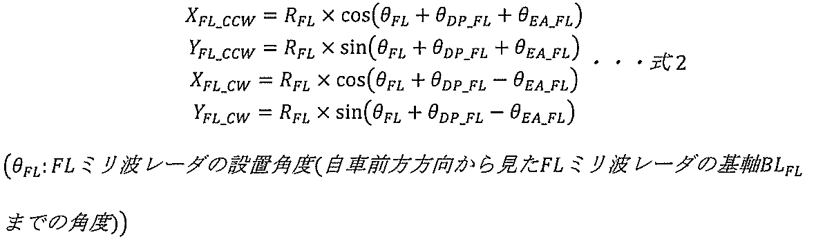

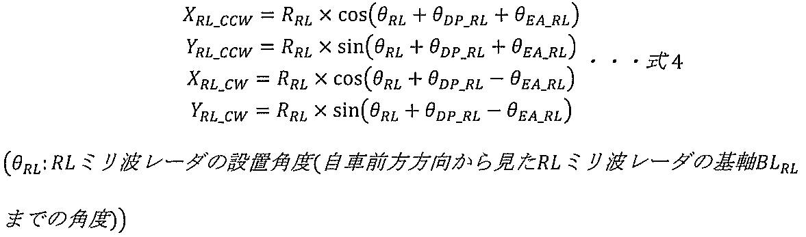

図10は、前記処理S54、および、前記処理S55で実施される各座標軸におけるフュージョン位置算出の説明図を示している。初めに処理S54にて、式6に基づいてX軸方向フュージョン位置Xfusionを算出する。ここで重みwX_FLは、二つの検知代表点の間の比率を決定するパラメータであり、式7に示すように処理S53で得られた各検知代表点が持つX軸方向の誤差量(車両座標系における想定誤差)の比で決定する。


次に処理S55にて、Y軸方向についても同様に、式8および式9に基づいてY軸方向フュージョン位置Yfusionを算出する。


以上で処理S5が終了し、最終的なフュージョン位置Ofusionが設定される。
本実施例では、誤差量(車両座標系における想定誤差)の比に基づいてフュージョン位置を設定することで、ミリ波レーダの持つ誤差指向性を考慮した上でより存在確率の高い位置を推定することが可能となる。また、各ミリ波レーダで誤差円弧のマップを個別に持つことにより、例えば異なるサプライヤーのミリ波レーダ同士のフュージョンにも採用することができ、汎用性高く適用することが可能である。
[実施例2]
次に、本発明の実施例2を図11~図20を参照しつつ説明する。
次に、本発明の実施例2を図11~図20を参照しつつ説明する。
本発明の実施例2として、実施例1の処理S52で算出される誤差円弧をベース誤差円弧として定義し、各ミリ波レーダの設置高さ、SN比(信号対雑音比)、レーザー反射強度等に基づいてベース誤差円弧の大きさ(測定誤差に対応)を調整することで、処理S53の入力情報となる誤差円弧を定義する処理を説明する。また、実施例1とは異なるシーンとして、RLミリ波レーダH13とRRミリ波レーダH14によってフュージョンを行うシーンを例にとり、処理を説明する。なお、実施例2と前記実施例1とで同じ部位や同じ処理には同じ符号を付し、その説明は繰り返さない。
図11に、実施例2における処理S5の詳細フローチャートを示している。
初めに処理S51にて、検知代表点同士のペア判定を行うが、処理S51は実施例1と同じである。
次に処理S52-1にて、処理S51で得られた(ペアとなる)2つの検知代表点に対してそれぞれベース誤差円弧を定義する。ベース誤差円弧は、実施例1の処理S52で定義された誤差円弧と同義であるため、説明は割愛する。
次に処理S52-2にて、各ミリ波レーダの設置高さ、SN比、レーザー反射強度等に基づいて算出するゲインによって処理S52-1で得られた各ベース誤差円弧の大きさを調整する。
以降の処理S53、処理S54、処理S55は実施例1と同じであるため、説明を割愛する。
図12に、本実施例2で想定するシーン例の説明図を示している。本シーンでは、RLミリ波レーダH13の検知エリアARLとRRミリ波レーダH14の検知エリアARRが重畳する領域において歩行者物標OPEDが存在する場合の処理について説明する。
図13は、前記処理S51で実施されるペア判定の説明図を示している。処理S4より得られるRLミリ波レーダH13の検知代表点DPRLの位置座標(XRL,YRL)とRRミリ波レーダH14の検知代表点DPRRの位置座標(XRR,YRR)から、以下の判定式10を満足すれば、ペア判定成立となる。

図14は、前記処理S52-1で実施されるベース誤差円弧算出の説明図を示している。ただし、図が煩雑になるのを防ぐため、ベース誤差円弧を定義するための過程となる情報はRRミリ波レーダH14に関するものしか記載していない。実施例1と同様に、検知代表点までの直線距離と、検知代表点の向きとミリ波レーダ基軸が成す角度を引数とした3次元マップで設定されるベース誤差円弧角度θbase_RRによって、RRミリ波レーダH14の検知代表点DPRRのベース誤差円弧EAbase_RRが定義される。RLミリ波レーダH13の検知代表点DPRLのベース誤差円弧EAbase_RLも同様に定義される。
図15は、前記処理S52-2で実施される誤差円弧算出の説明図を示している。ただし、図が煩雑になるのを防ぐため、誤差円弧を定義するための過程となる情報はRRミリ波レーダH14に関するものしか記載していない。各ミリ波レーダの設置高さの差、SN比の差、レーザー反射強度の差に基づいた式11によってベース誤差円弧角度を調整するための誤差円弧調整ゲインを算出する。ただし、これらのゲイン項目は一例であり、本実施例の趣旨の再現が可能であれば、任意のパラメータに基づくゲイン項目を追加設定することが可能である。
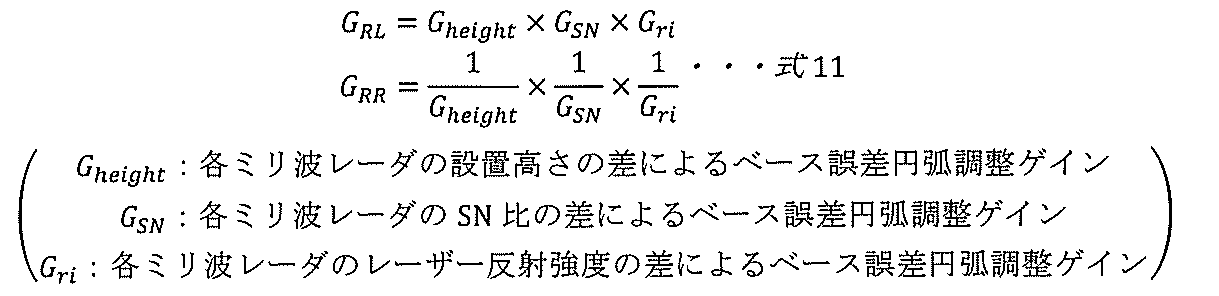
次に、式11により算出された各検知代表点に対する各ベース誤差円弧調整ゲインに基づいた式12によって検知代表点DPRLの誤差円弧角度θRLと検知代表点DPRRの誤差円弧角度θRRを算出する。

式12により算出された各誤差円弧角度によってRLミリ波レーダH13の検知代表点DPRLの誤差円弧EARL、RRミリ波レーダH14の検知代表点DPRRの誤差円弧EARRが定義される。これにより、各ミリ波レーダの設置高さ、SN比(信号対雑音比)、レーザー反射強度等の違いに基づいてベース誤差円弧の大きさ(測定誤差に対応)を調整して誤差円弧を定義する。
図16は、式11にて用いられる各ミリ波レーダの設置高さの差によるベース誤差円弧調整ゲインGheightの一例を説明したものである。RLミリ波レーダの設置高さHRLから見たRRミリ波レーダの設置高さHRRとの差が大きいほど設置高さの差によるベース誤差円弧調整ゲインGheightが大きくなるような設定とすることが好ましい。これは、ミリ波レーダの設置高さが高いほどレーザー照射方向が地面に向かうことになり、地面からの反射波を拾いやすく、検知精度が低くなるミリ波レーダの持つ特性を考慮したマップとなっている。ただし、図16中の設置高さの差によるベース誤差円弧調整ゲインGheightの関係は一例であり、本実施例の趣旨の再現が可能であれば、任意に設定可能とする。
図17は、式11にて用いられる各ミリ波レーダのSN比の差によるベース誤差円弧調整ゲインGSNの一例を説明したものである。SN比とは、信号処理における有効な信号成分(シグナル)と雑音(ノイズ)成分との量の比であり、SN比が大きいほどノイズを多く含み、ミリ波レーダの検知精度が低いことを表す。そのため、SN比が大きい方の誤差円弧が大きくなるようなSN比の差によるベース誤差円弧調整ゲインGSNの設定とすることが好ましい。ただし、図17中のSN比の差によるベース誤差円弧調整ゲインGSNの関係は一例であり、本実施例の趣旨の再現が可能であれば、任意に設定可能とする。
図18は、式11にて用いられる各ミリ波レーダのレーザー反射強度の差によるベース誤差円弧調整ゲインGriの一例を説明したものである。レーザー反射強度とは、物標で反射したレーザー波をどれだけ多く受信できたかを表すパラメータであり、レーザー反射強度が高い状態の方がミリ波レーダの検知精度が高いことを表す。そのため、レーザー反射強度が小さい方の誤差円弧が大きくなるようなレーザー反射強度の差によるベース誤差円弧調整ゲインGriの設定とすることが好ましい。ただし、図18中のレーザー反射強度の差によるベース誤差円弧調整ゲインGriの関係は一例であり、本実施例の趣旨の再現が可能であれば、任意に設定可能とする。
図19は、前記処理S53で実施される誤差円弧の分解の説明図を示している。処理S52-2により定義されたRLミリ波レーダH13の誤差円弧EARLに対し、実施例1と同様に式4及び式5に基づいてそれぞれX軸方向誤差量ΔXRL、Y軸方向誤差量ΔYRLを算出する。
同様にRRミリ波レーダH14の誤差円弧EARRに対しても式13に基づいた座標変換によって誤差円弧EARRの反時計回り側の端点のXY座標(XRR_CCW,YRR_CCW)と時計回り側の端点のXY座標(XRR_CW,YRR_CW)を算出し、式14に基づいてX軸方向誤差量ΔXRRとY軸方向誤差量ΔYRRを算出する。
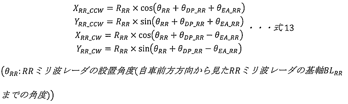

図20は、前記処理S54、および、前記処理S55で実施される各座標軸におけるフュージョン位置算出の説明図を示している。初めに処理S54にて、式15に基づいてX軸方向フュージョン位置Xfusionを算出する。ここで重みwX_RLは、2つの検知代表点の間の比率を決定するパラメータであり、式16に示すように処理S53で得られた各検知代表点が持つX軸方向の誤差量(車両座標系における想定誤差)の比で決定する。


次に処理S55にて、Y軸方向についても同様に、式17および式18に基づいてY軸方向フュージョン位置Yfusionを算出する。


以上で処理S5が終了し、最終的なフュージョン位置Ofusionが設定される。
本実施例では、各ミリ波レーダの設置高さ、SN比(信号対雑音比)、レーザー反射強度等に基づいて誤差円弧の大きさ(測定誤差に対応)を調整できるため、例えば別々のサプライヤーのミリ波レーダ同士のフュージョンにも適用できるだけでなく、フュージョンシステムを搭載する車両の変化に対しても、汎用性高く適用することが可能である。
以上で説明したように、本実施例のコントローラ(車両制御装置)H3は、車両の周囲の物体を検知して前記車両を制御する車両制御装置であって、第1のミリ波レーダと前記第1のミリ波レーダとは異なる位置に設置された第2のミリ波レーダを有し、前記第1のミリ波レーダにより検知される前記物体の第1の測距位置及び第1の測定誤差と前記第2のミリ波レーダにより検知される前記物体の第2の測距位置及び第2の測定誤差とに基づいて前記物体を検知する。
また、前記第1の測定誤差及び前記第2の測定誤差(ひいては前記物体の検知誤差)は、電波(レーザー)照射方向の測定誤差及び前記電波(レーザー)照射方向の垂直方向の測定誤差をそれぞれ含む。
また、前記第1の測定誤差及び前記第2の測定誤差のそれぞれを前記車両の前後(長さ)方向と前記車両の左右(幅)方向に分解して前記第1のミリ波レーダ及び前記第2のミリ波レーダのそれぞれの車両座標系における想定誤差を算出し、前記第1のミリ波レーダ及び前記第2のミリ波レーダのそれぞれの車両座標系における想定誤差を基に決定される所定の割合に基づいて(前記第1の測距位置及び前記第2の測距位置から)前記物体の前記車両の前後(長さ)方向と前記車両の左右(幅)方向のそれぞれの合成位置(フュージョン位置)を算出する。
また、前記所定の割合は、前記第1のミリ波レーダの車両座標系における想定誤差と前記第2のミリ波レーダの車両座標系における想定誤差との比に基づいて決定される。
すなわち、本実施例は、2つ以上のミリ波レーダで構成される、自車両の走行する位置及び走行環境の情報等を取得する外界情報取得装置を備えた車両を対象とし、自車の側方や後方に存在する周囲の障害物を検知するシーンにて、同一物標に対する2つのミリ波レーダの各検知点に基づき各検知点の誤差円弧を車両進行(前後)方向と車両左右方向に分解した誤差量の割合に基づいてフュージョンすることにより、高精度かつ汎用性の高いセンシングが可能な車両制御装置を提供する。
本実施例によれば、ミリ波レーダのみで高精度かつ汎用性高く側方や後方などをセンシングすることが可能な車両制御装置を提供することができる。
なお、本発明は上述の実施例に限定されるものではなく、様々な変形例が含まれる。例えば、上記した実施例は本発明を分かりやすく説明するために詳細に説明したものであり、必ずしも説明した全ての構成を備えるものに限定されるものではない。
また、上記の各構成、機能、処理部、処理手段等は、それらの一部又は全部を、例えば集積回路で設計する等によりハードウェアで実現してもよい。また、上記の各構成、機能等は、プロセッサがそれぞれの機能を実現するプログラムを解釈し、実行することによりソフトウェアで実現してもよい。各機能を実現するプログラム、テーブル、ファイル等の情報は、メモリや、ハードディスク、SSD(Solid State Drive)等の記録装置、または、ICカード、SDカード、DVD等の記録媒体に置くことができる。
H1 外界情報取得部
H11 FLミリ波レーダ
H12 FRミリ波レーダ
H13 RLミリ波レーダ
H14 RRミリ波レーダ
H2 自車両情報取得部
H3 コントローラ(車両制御装置)
H4 車両制御部
H11 FLミリ波レーダ
H12 FRミリ波レーダ
H13 RLミリ波レーダ
H14 RRミリ波レーダ
H2 自車両情報取得部
H3 コントローラ(車両制御装置)
H4 車両制御部
Claims (8)
- 車両の周囲の物体を検知して前記車両を制御する車両制御装置であって、
第1のミリ波レーダと前記第1のミリ波レーダとは異なる位置に設置された第2のミリ波レーダを有し、
前記第1のミリ波レーダにより検知される前記物体の第1の測距位置及び第1の測定誤差と前記第2のミリ波レーダにより検知される前記物体の第2の測距位置及び第2の測定誤差とに基づいて前記物体を検知することを特徴とする車両制御装置。 - 請求項1に記載の車両制御装置であって、
前記第1の測定誤差及び前記第2の測定誤差は、電波照射方向の測定誤差及び前記電波照射方向の垂直方向の測定誤差をそれぞれ含むことを特徴とする車両制御装置。 - 請求項2に記載の車両制御装置であって、
前記第1の測定誤差及び前記第2の測定誤差のそれぞれを前記車両の前後方向と前記車両の左右方向に分解して前記第1のミリ波レーダ及び前記第2のミリ波レーダのそれぞれの車両座標系における想定誤差を算出し、前記第1のミリ波レーダ及び前記第2のミリ波レーダのそれぞれの車両座標系における想定誤差を基に決定される所定の割合に基づいて前記物体の前記車両の前後方向と前記車両の左右方向のそれぞれの合成位置を算出することを特徴とする車両制御装置。 - 請求項3に記載の車両制御装置であって、
前記所定の割合は、前記第1のミリ波レーダの車両座標系における想定誤差と前記第2のミリ波レーダの車両座標系における想定誤差との比に基づいて決定されることを特徴とする車両制御装置。 - 請求項1に記載の車両制御装置であって、
前記第1のミリ波レーダ及び前記第2のミリ波レーダは同じ特性を有することを特徴とする車両制御装置。 - 請求項1に記載の車両制御装置であって、
前記第1の測定誤差及び前記第2の測定誤差は、前記第1のミリ波レーダと前記第2のミリ波レーダの設置高さの違いによって調整できることを特徴とする車両制御装置。 - 請求項1に記載の車両制御装置であって、
前記第1の測定誤差及び前記第2の測定誤差は、前記第1のミリ波レーダと前記第2のミリ波レーダのSN比の違いによって調整できることを特徴とする車両制御装置。 - 請求項1に記載の車両制御装置であって、
前記第1の測定誤差及び前記第2の測定誤差は、前記第1のミリ波レーダと前記第2のミリ波レーダのレーザー反射強度の違いによって調整できることを特徴とする車両制御装置。
Priority Applications (2)
| Application Number | Priority Date | Filing Date | Title |
|---|---|---|---|
| PCT/JP2022/045167 WO2024121995A1 (ja) | 2022-12-07 | 2022-12-07 | 車両制御装置 |
| JP2024562494A JP7814554B2 (ja) | 2022-12-07 | 2022-12-07 | 車両制御装置 |
Applications Claiming Priority (1)
| Application Number | Priority Date | Filing Date | Title |
|---|---|---|---|
| PCT/JP2022/045167 WO2024121995A1 (ja) | 2022-12-07 | 2022-12-07 | 車両制御装置 |
Publications (1)
| Publication Number | Publication Date |
|---|---|
| WO2024121995A1 true WO2024121995A1 (ja) | 2024-06-13 |
Family
ID=91379096
Family Applications (1)
| Application Number | Title | Priority Date | Filing Date |
|---|---|---|---|
| PCT/JP2022/045167 Ceased WO2024121995A1 (ja) | 2022-12-07 | 2022-12-07 | 車両制御装置 |
Country Status (2)
| Country | Link |
|---|---|
| JP (1) | JP7814554B2 (ja) |
| WO (1) | WO2024121995A1 (ja) |
Citations (6)
| Publication number | Priority date | Publication date | Assignee | Title |
|---|---|---|---|---|
| JP2006046962A (ja) * | 2004-07-30 | 2006-02-16 | Toyota Motor Corp | 物標検出装置 |
| JP2019002691A (ja) * | 2017-06-09 | 2019-01-10 | トヨタ自動車株式会社 | 物標情報取得装置 |
| WO2019097731A1 (ja) * | 2017-11-20 | 2019-05-23 | 三菱電機株式会社 | 障害物認識装置および障害物認識方法 |
| CN110907905A (zh) * | 2019-11-21 | 2020-03-24 | 重庆长安汽车股份有限公司 | 一种毫米波雷达安装位置的标定装置及方法 |
| JP2020159925A (ja) * | 2019-03-27 | 2020-10-01 | 株式会社Soken | 物体検出装置 |
| WO2022014270A1 (ja) * | 2020-07-15 | 2022-01-20 | ソニーグループ株式会社 | 情報処理装置、情報処理方法および情報処理プログラム |
-
2022
- 2022-12-07 WO PCT/JP2022/045167 patent/WO2024121995A1/ja not_active Ceased
- 2022-12-07 JP JP2024562494A patent/JP7814554B2/ja active Active
Patent Citations (6)
| Publication number | Priority date | Publication date | Assignee | Title |
|---|---|---|---|---|
| JP2006046962A (ja) * | 2004-07-30 | 2006-02-16 | Toyota Motor Corp | 物標検出装置 |
| JP2019002691A (ja) * | 2017-06-09 | 2019-01-10 | トヨタ自動車株式会社 | 物標情報取得装置 |
| WO2019097731A1 (ja) * | 2017-11-20 | 2019-05-23 | 三菱電機株式会社 | 障害物認識装置および障害物認識方法 |
| JP2020159925A (ja) * | 2019-03-27 | 2020-10-01 | 株式会社Soken | 物体検出装置 |
| CN110907905A (zh) * | 2019-11-21 | 2020-03-24 | 重庆长安汽车股份有限公司 | 一种毫米波雷达安装位置的标定装置及方法 |
| WO2022014270A1 (ja) * | 2020-07-15 | 2022-01-20 | ソニーグループ株式会社 | 情報処理装置、情報処理方法および情報処理プログラム |
Also Published As
| Publication number | Publication date |
|---|---|
| JP7814554B2 (ja) | 2026-02-16 |
| JPWO2024121995A1 (ja) | 2024-06-13 |
Similar Documents
| Publication | Publication Date | Title |
|---|---|---|
| CN108238047B (zh) | 驾驶辅助装置 | |
| CN110073429B (zh) | 用于监控车辆组合的车辆周围环境的方法以及监控系统 | |
| JP6358017B2 (ja) | 運転支援装置 | |
| EP3913392B1 (en) | Method and apparatus for rear cross collision warning | |
| JP6424467B2 (ja) | 物標検出装置 | |
| US11235741B2 (en) | Vehicle and control method for the same | |
| WO2017145845A1 (ja) | 衝突予測装置 | |
| US12623655B2 (en) | Vehicle for avoiding collision and method of operating the vehicle | |
| JP7028982B2 (ja) | レーダ処理装置 | |
| KR20220000073A (ko) | 거리센서를 이용한 장애물 검출 시스템 및 방법 | |
| WO2022030186A1 (ja) | 車両および障害物検知装置 | |
| US20240034286A1 (en) | Collision avoidance assistance device | |
| WO2021106510A1 (ja) | 障害物認識装置 | |
| JP7579983B2 (ja) | 外界認識装置 | |
| CN116968725A (zh) | 一种自动泊车的碰撞预警方法、系统及存储介质 | |
| JP7814554B2 (ja) | 車両制御装置 | |
| JP6720954B2 (ja) | 車両の物標検出装置 | |
| JP6256795B2 (ja) | 障害物検知装置 | |
| JP6818902B2 (ja) | 車両検知システム | |
| KR102722257B1 (ko) | 운전자 보조 시스템 및 그 제어 방법 | |
| JP6462610B2 (ja) | 横断判定装置 | |
| WO2024161481A1 (ja) | 車両制御装置 | |
| WO2022034775A1 (ja) | 衝突判定装置、衝突判定方法および衝突回避システム | |
| JP7814553B2 (ja) | 衝突回避支援装置 | |
| KR102951036B1 (ko) | 복수의 센서를 이용한 장애물 감지 시스템 및 방법 |
Legal Events
| Date | Code | Title | Description |
|---|---|---|---|
| 121 | Ep: the epo has been informed by wipo that ep was designated in this application |
Ref document number: 22967845 Country of ref document: EP Kind code of ref document: A1 |
|
| WWE | Wipo information: entry into national phase |
Ref document number: 2024562494 Country of ref document: JP |
|
| NENP | Non-entry into the national phase |
Ref country code: DE |
|
| 122 | Ep: pct application non-entry in european phase |
Ref document number: 22967845 Country of ref document: EP Kind code of ref document: A1 |