WO2024121968A1 - 搬送装置および搬送方法 - Google Patents
搬送装置および搬送方法 Download PDFInfo
- Publication number
- WO2024121968A1 WO2024121968A1 PCT/JP2022/045079 JP2022045079W WO2024121968A1 WO 2024121968 A1 WO2024121968 A1 WO 2024121968A1 JP 2022045079 W JP2022045079 W JP 2022045079W WO 2024121968 A1 WO2024121968 A1 WO 2024121968A1
- Authority
- WO
- WIPO (PCT)
- Prior art keywords
- center frame
- guide mechanism
- frame
- groove
- transport device
- Prior art date
- Legal status (The legal status is an assumption and is not a legal conclusion. Google has not performed a legal analysis and makes no representation as to the accuracy of the status listed.)
- Ceased
Links
Images

















Classifications
-
- B—PERFORMING OPERATIONS; TRANSPORTING
- B65—CONVEYING; PACKING; STORING; HANDLING THIN OR FILAMENTARY MATERIAL
- B65G—TRANSPORT OR STORAGE DEVICES, e.g. CONVEYORS FOR LOADING OR TIPPING, SHOP CONVEYOR SYSTEMS OR PNEUMATIC TUBE CONVEYORS
- B65G1/00—Storing articles, individually or in orderly arrangement, in warehouses or magazines
-
- B—PERFORMING OPERATIONS; TRANSPORTING
- B65—CONVEYING; PACKING; STORING; HANDLING THIN OR FILAMENTARY MATERIAL
- B65G—TRANSPORT OR STORAGE DEVICES, e.g. CONVEYORS FOR LOADING OR TIPPING, SHOP CONVEYOR SYSTEMS OR PNEUMATIC TUBE CONVEYORS
- B65G1/00—Storing articles, individually or in orderly arrangement, in warehouses or magazines
- B65G1/02—Storage devices
- B65G1/04—Storage devices mechanical
- B65G1/10—Storage devices mechanical with relatively movable racks to facilitate insertion or removal of articles
-
- B—PERFORMING OPERATIONS; TRANSPORTING
- B65—CONVEYING; PACKING; STORING; HANDLING THIN OR FILAMENTARY MATERIAL
- B65G—TRANSPORT OR STORAGE DEVICES, e.g. CONVEYORS FOR LOADING OR TIPPING, SHOP CONVEYOR SYSTEMS OR PNEUMATIC TUBE CONVEYORS
- B65G1/00—Storing articles, individually or in orderly arrangement, in warehouses or magazines
- B65G1/02—Storage devices
- B65G1/04—Storage devices mechanical
- B65G1/137—Storage devices mechanical with arrangements or automatic control means for selecting which articles are to be removed
Definitions
- This disclosure relates to a transport device and a transport method for transporting a cart containing items.
- Carts for storing items are equipped with a front frame, a rear frame facing the front frame, a center frame connecting the front and rear frames, and multiple casters attached to the bottom mechanism, and are used in a variety of situations. Recently, in order to save labor, the method of moving carts has evolved from manual movement to automatic movement.
- the present disclosure has been made to solve these problems, and aims to provide a transport device and transport method that can prevent strong stress from being placed on the center frame of the cart while keeping manufacturing costs down.
- the transport device disclosed herein transports a cart having a front frame, a rear frame facing the front frame, a center frame connecting the front frame and the rear frame, front and rear connecting fittings attached to the center frame so as to protrude in a direction different from the extension direction of the center frame, and a plurality of casters, and is provided with a main body mechanism that supports the entire transport device, an equipment drive unit attached to the main body mechanism that drives the transport device, a guide mechanism having a center frame groove that can be fitted into the center frame, a guide mechanism drive unit that drives the guide mechanism in the height direction, a group of sensors that detects the surrounding conditions of the transport device, and a control unit that controls the equipment drive unit and the guide mechanism drive unit, and the control unit controls the equipment drive unit and the guide mechanism drive unit based on the detection results of the group of sensors so that the center frame fits into the center frame groove, and when the center frame fits into the center frame groove, the guide mechanism is positioned between the front and rear connecting fittings.
- This disclosure makes it possible to reduce manufacturing costs while preventing strong stress from being placed on the center frame of the cart.
- FIG. 1 is a block diagram showing an example of a configuration of a transport device according to a first embodiment
- 1 is a block diagram showing an example of a configuration of a transport device according to a first embodiment
- FIG. 2 is a diagram showing an example of a configuration of a cart according to the first embodiment
- 4 is a plan view showing a state in which the center frame groove and the center frame according to the first embodiment are fitted together
- FIG. This is a cross-sectional view taken along line A1-A1 of FIG.
- FIG. 5 is a side view of FIG. 5 is a flowchart showing an example of an operation of the transport device according to the first embodiment.
- 5A to 5C are diagrams for explaining the movement of the transport device according to the first embodiment.
- FIG. 5A to 5C are diagrams for explaining the movement of the transport device according to the first embodiment.
- 5A to 5C are diagrams for explaining the movement of the transport device according to the first embodiment.
- 5A to 5C are diagrams for explaining the movement of the transport device according to the first embodiment.
- 10 is a diagram for explaining the allowable elevation angle between the center frame and the center frame groove according to the first embodiment.
- FIG. 13 is a plan view showing a state in which a center frame groove and a center frame according to the second embodiment are fitted together.
- FIG. This is a cross-sectional view taken along B1-B1 in FIG.
- FIG. 14 is a side view of FIG.
- FIG. 13 is a diagram for explaining the relationship between the presence or absence of a first guide mechanism according to the second embodiment and the allowable position error between a center frame groove and a center frame.
- FIG. 13 is a diagram for explaining the relationship between the presence or absence of a first guide mechanism according to the second embodiment and the allowable position error between a center frame groove and a center frame.
- FIG. 13 is a diagram for explaining the relationship between the presence or absence of a first guide mechanism according to the second embodiment and the allowable position error between a center frame groove and a center frame.
- FIG. 13A to 13C are diagrams for explaining the action of a first induction mechanism according to the second embodiment.
- FIG. 13A to 13C are diagrams illustrating an example of a shape of a first guide mechanism according to a second modification of the second embodiment.
- 13 is a diagram for explaining the installation position of the first guiding mechanism in the third modification of the second embodiment.
- FIG. 13 is a plan view showing a state in which a center frame groove and a center frame according to embodiment 3 are fitted together.
- FIG. This is a cross-sectional view taken along C1-C1 in FIG. 22.
- FIG. 23 is a side view of FIG. 13 is a side view showing a state in which the center frame groove and the center frame are fitted together according to the first modified example of the third embodiment.
- FIG. 13 is a side view showing a state in which the center frame groove and the center frame according to the second modification of the third embodiment are fitted together.
- FIG. 13 is an external view showing a state in which the transport device and the cart according to the fourth embodiment are fitted together;
- FIG. 13 is a plan view showing a state in which a center frame groove and a center frame according to a fourth embodiment are fitted together.
- FIG. This is a cross-sectional view taken along D1-D1 in FIG. 28.
- FIG. 29 is a side view of FIG.
- FIG. 13 is a plan view showing an example of a guide mechanism according to embodiment 4.
- FIG. 13 is a plan view showing an example of a guide mechanism according to a first modified example of the fourth embodiment.
- FIG. 13 is a plan view showing a state in which a center frame groove and a center frame are fitted together according to a second modification of the fourth embodiment;
- FIG. FIG. 34 is a side view of FIG.
- FIG. 1 is a diagram illustrating an example of a hardware configuration of a conveying device according to the first to fourth embodiments.
- FIG. 1 is a diagram illustrating an example of a hardware configuration of a conveying device according to the first to fourth embodiments.
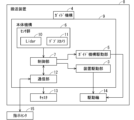
- FIG. 1 is a block diagram showing an example of a configuration of a conveying device 1 according to the first embodiment.
- the conveying device 1 includes a main body mechanism 2 and a guide mechanism 4.
- the main body mechanism 2 includes a device drive unit 3, a guide mechanism drive unit 5, a sensor group 6, and a control unit 7.
- the guide mechanism 4 has a center frame groove 25 that can fit into the center frame 18 that constitutes the cart described below (see FIG. 4, for example).
- the main body mechanism 2 supports the entire transport device 1.
- the device drive unit 3 drives the transport device 1.
- the guide mechanism drive unit 5 drives the guide mechanism 4 in the height direction.
- the sensor group 6 detects the surrounding conditions of the transport device 1.
- the control unit 7 controls the device drive unit 3 and the guide mechanism drive unit 5. Specifically, the control unit 7 controls the device drive unit 3 and the guide mechanism drive unit 5 based on the detection results of the sensor group 6 so that the center frame 18 fits into the center frame groove 25.
- the guide mechanism 4 is located between the front connecting fitting 23 and the rear connecting fitting 24 that make up the cart described below (see Figure 4, for example).
- FIG. 2 is a block diagram showing an example of the configuration of the transport device 8 relating to another configuration.
- FIG. 3 is a diagram showing an example of the configuration of the cart transported by the transport device 8. Below, the configuration of the cart will be described first, and then the configuration of the transport device 8 will be described.
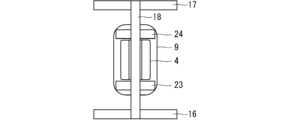
- the cart includes a front frame 16 , a rear frame 17 , a center frame 18 , casters 19 , caster brakes 20 , a support frame 21 , and a tray 22 .
- the front frame 16 is a frame provided at the front of the cart.
- the rear frame 17 is a frame provided at the rear of the cart, facing the front frame 16.
- the center frame 18 is a frame that connects the front frame 16 and the rear frame 17.
- the front connecting fitting 23 is attached to the center frame 18 so that it protrudes in a direction different from the extension direction of the center frame 18.
- the front connecting fitting 23 is located closer to the front frame 16 than the guide mechanism 4.
- the rear connecting fitting 24 is attached to the center frame 18 so that it protrudes in a direction different from the extension direction of the center frame 18.
- the rear connecting fitting 24 is located closer to the rear frame 17 than the guide mechanism 4.
- the casters 19 are provided on the left and right ends of the front frame 16, and on the left and right ends of the rear frame 17.
- the caster brakes 20 are used to lock the casters 19 in place so that they do not move. When the user operates the caster brakes 20, the casters 19 are locked in place, stopping the movement of the cart.
- the support frame 21 is provided vertically on each of the front frame 16 and the rear frame 17.
- the tray 22 is placed on the support frame 21, and items can be placed on the tray 22.
- center frame 18 may be structured to protrude from both or either of the front frame 16 and the rear frame 17.
- the transport device 8 includes a guide mechanism 4, a main body mechanism 9, casters 13, and drive wheels 14.
- the casters 13 are provided at the four corners of the main body mechanism 9.
- the guide mechanism 4 is provided integrally with the main body mechanism 9, and has a center frame groove 25 that can be fitted into the center frame 18 of the cart.
- the main body mechanism 9 includes a device drive unit 3, a guide mechanism drive unit 5, a sensor group 6, a control unit 7, and a communication unit 12.
- the device drive unit 3 is a motor that rotates and drives the drive wheels 14 according to instructions from the control unit 7.
- the drive wheels 14 are provided on the left and right sides of the main mechanism 9. It is to be noted that a device drive unit 3 may be provided for each drive wheel 14.
- the drive wheels 14 are not limited to wheels, and may be other forms of movement such as caterpillar tracks.
- the drive wheels 14 are not limited to a configuration in which a pair is provided on the left and right sides of the main mechanism 9, and may be provided in any configuration, such as multiple pairs.
- the sensor group 6 includes a Lidar 10 and a depth camera 11.
- the Lidar 10 detects obstacles in the space surrounding the transport device 8 and detects its own position for SLAM (Simultaneous Localization and Mapping) driving. Obstacles in the space surrounding the transport device 8 include each part that makes up the cart.
- SLAM Simultaneous Localization and Mapping
- the depth camera 11 photographs the area around the transport device 8 to obtain a distance image, and performs image processing on the obtained distance image to determine the distance to obstacles present around the transport device 8.
- the range of the depth camera 11 is approximately 10 cm. Obstacles present around the transport device 8 include each part that makes up the cart.
- the guide mechanism drive unit 5 is a lifting motor that changes the height of the guide mechanism 4 from the floor surface.
- the guide mechanism drive unit 5 drives the drive wheels 14 to push them down from the main mechanism 9, or drives the drive wheels 14 to accommodate them in the main mechanism 9, according to instructions from the control unit 7.
- the guide mechanism drive unit 5 drives the drive wheels 14 so as to push them down from the main mechanism 9, the main mechanism 9 is accordingly pushed up from the floor surface and reaches its normal height. At this time, the position of the guide mechanism 4, which is configured integrally with the main mechanism 9, also rises to its normal height.
- the main mechanism 9 accordingly assumes a low-floor state lower than the normal height state. At this time, the position of the guide mechanism 4 configured integrally with the main mechanism 9 is also lowered to assume the low-floor state.
- the control unit 7 controls the entire conveying device 8, including the device drive unit 3 and the guide mechanism drive unit 5.
- the communication unit 12 communicates with an instruction center 15 that is provided outside the transport device 8.
- the instruction center 15 monitors the transport device 8 and instructs the transport device 8 to transport the cart.
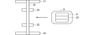
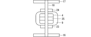
- Fig. 4 is a plan view showing a state in which the center frame 18 of the cart and the center frame groove 25 of the guide mechanism 4 are fitted together.
- Fig. 5 is a cross-sectional view taken along the line A1-A1 of Fig. 4.
- Fig. 6 is a side view of Fig. 4.
- the guide mechanism 4 is located between the front connecting fitting 23 and the rear connecting fitting 24.
- the guide mechanism 4 comes into contact with the front connecting fitting 23 or the rear connecting fitting 24.
- the front connecting fitting 23 and the rear connecting fitting 24 are in contact with the main mechanism 9 in the vertical direction, but they do not have to come into contact with the main mechanism 9 in the vertical direction. In other words, it is sufficient that the front connecting fitting 23 or the rear connecting fitting 24 comes into contact with and supports the guide mechanism 4 when the transport device 8 moves the cart in the front-to-rear direction.
- the center frame 18 fits into the center frame groove 25. Then, when the transport device 8 turns the cart, the center frame groove 25 comes into contact with the center frame 18. Note that there may be some play between the center frame groove 25 and the center frame 18, for example a gap of about 1 mm or more on the left and right.
- the control unit 7 is equipped with a SoC (System on a Chip) and has a built-in program that allows the entire transport device 8 to operate autonomously.
- SoC System on a Chip
- FIG. 7 is a flowchart showing an example of the operation of the conveying device 8.
- step S1 the control unit 7 receives a movement command sent from the instruction center 15 via the communication unit 12.
- the movement command is a command that indicates that the cart stopped at point Pa should be transported to destination Pb.
- the movement command includes position information of the cart (position information of point Pa) and position information of the destination of the cart (position information of destination Pb).
- step S2 the control unit 7 calculates a route from the waiting position Prest of the transport device 8 to the point Pa where the cart is located, based on map information inside the building (not shown). Then, the control unit 7 controls the device driving unit 3 to drive autonomously to the point Pa while avoiding moving objects or obstacles that exist around the transport device 8, based on the surrounding conditions detected by the sensor group 6 including the Lidar 10 and the depth camera 11. When the control unit 7 finds a cart near the point Pa, it controls the device driving unit 3 to stop the transport device 8. The transport device 8 drives from the waiting position Pret to the point Pa at a normal height.
- control unit 7 calculates the route from the standby position Prest to the point Pa, this is not limiting.
- the instruction center 15 may calculate the route from the standby position Prest to the point Pa and notify the transport device 8.
- Map information for the building may be stored by the control unit 7, or may be obtained from an external source such as the instruction center 15 as necessary.
- step S3 the control unit 7 formulates a movement plan for having the transport device 8 slip under the cart. Then, based on the formulated movement plan and the surrounding conditions detected by the Lidar 10 and the depth camera 11, the control unit 7 controls the device driving unit 3 so that the transport device 8 slips under the cart.
- Figures 8 and 9 show the transport device 8 slipping under the cart. At this time, the transport device 8 slips under the cart after changing from the normal height state to the low-floor state.
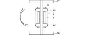
- step S4 the control unit 7 controls the device drive unit 3 so that the center frame 18 and the center frame groove 25 of the guide mechanism 4 are aligned in a planar view based on the position of the cart's center frame 18 detected by the Lidar 10 and the depth camera 11.
- Figure 10 shows the state after the transport device 8 has rotated (pivoted) so that the center frame and the center frame groove 25 of the guide mechanism 4 are aligned in a planar view.
- step S5 the control unit 7 controls the guide mechanism drive unit 5 so that the conveying device 8 is at its normal height.
- the center frame groove 25 fits into the center frame 18.
- step S6 the control unit 7 calculates a route from point Pa to destination Pb based on map information inside a building (not shown). Then, based on the surrounding conditions detected by the Lidar 10 and the depth camera 11, the control unit 7 controls the device drive unit 3 to autonomously travel to destination Pb while avoiding moving objects or obstacles that exist around the transport device 8. In this way, the cart is transported from point Pa to destination Pb.
- Figure 11 shows how the transport device 8 transports the cart.
- control unit 7 calculates the route from point Pa to destination Pb, but this is not limited to the case.
- the instruction center 15 may also calculate the route from point Pa to destination Pb and notify the transport device 8.
- the control unit 7 of the transport device 8 When the cart arrives at destination Pb, staff inside the building collect the items placed on the tray 22 of the cart. After that, when the control unit 7 of the transport device 8 receives a command from the instruction center 15 via the communication unit 12 to return to the waiting position Pret, it controls the device drive unit 3 to travel autonomously from destination Pb to waiting position Pret.
- the movement command received by the control unit 7 from the instruction center 15 in step S1 may include a command to travel autonomously to waiting position Pret after the transport device 8 arrives at destination Pb.
- the conveying device 8 can be used, for example, to deliver medicine or food in a hospital, to deliver food in a school, to deliver food or goods in an office, or to transport parts in a manufacturing plant.
- the cart has a front connecting fitting 23 and a rear connecting fitting 24 that are provided on the center frame 18 so as to protrude in a direction different from the extension direction of the center frame 18.
- the guide mechanism 4 of the transport device 8 has a center frame groove 25 that can be fitted into the center frame 18. When the center frame 18 is fitted into the center frame groove 25, the guide mechanism 4 is located between the front connecting fitting 23 and the rear connecting fitting 24. With this configuration, strong stress is not applied to the center frame 18 when the transport device 8 transports the cart, so there is no need to strengthen the holding arms, and manufacturing costs can be reduced.
- the front connecting metal fitting 23 and the rear connecting metal fitting 24 are positioned to support the guide mechanism 4 in the front-rear direction, but the present invention is not limited to this.
- the front connecting metal fitting 23 and the rear connecting metal fitting 24 may be configured to support the transport device 8 when the cart is transported, and may be configured to support a part of the main body mechanism 9, for example.
- the guide mechanism 4 may be structured to be firmly fitted with the center frame 18, the front connecting metal fitting 23, and the rear connecting metal fitting 24.
- the elevation angle ⁇ between the center frame groove 25 of the guide mechanism 4 and the center frame 18 must be allowed within a pre-designed range.
- the elevation angle ⁇ is allowed, for example, within a range in which the gradient is greater than -5% and less than +5%. In this way, when the center frame groove 25 is fitted into the center frame 18, a predetermined gap is present between the center frame 18 and the center frame groove 25.
- the second embodiment is characterized by the provision of a guide mechanism (first guide mechanism 26, described below) to allow for positional errors in the left-right direction of the center frame 18 relative to the center frame groove 25.
- first guide mechanism 26 described below
- FIG. 13 is a plan view showing the state in which the center frame groove 25 and the center frame 18 according to the second embodiment are fitted together.
- FIG. 14 is a cross-sectional view taken along the line B1-B1 of FIG. 13.
- FIG. 15 is a side view of FIG. 13.
- a pair of first guide mechanisms 26 are provided at the front and rear ends of the center frame groove 25.
- the first guide mechanisms 26 are inclined toward the inside of the center frame groove 25, and are provided on opposite sides of the center frame groove 25.
- the width of the center frame groove 25 in embodiment 2 is wider than the width of the center frame groove in embodiment 1 by the width of the first guide mechanisms 26.
- FIG. 16 is a diagram showing the relationship between the center frame groove 25 and the center frame 18 in the absence of the first guide mechanism 26.
- the angle ⁇ of the slope of the first guide mechanism 26 be 45 degrees or more so that friction does not increase when the center frame 18 and the first guide mechanism 26 come into contact.
- Figure 19 is a diagram for explaining the action of the first guide mechanism 26. As shown in Figure 19, when the guide mechanism 4 rises, the center frame 18 comes into contact with the slope of the first guide mechanism 26 and is guided into the center frame groove 25. Then, the misalignment between the central axis of the center frame 18 and the central axis of the center frame groove 25 gradually decreases, and the center frame 18 fits into the center frame groove 25.
- a pair of first guide mechanisms 26 are provided at the front and rear ends of the center frame groove 25. This increases the allowable position error between the center frame groove 25 and the center frame 18 before the guide mechanism 4 is raised, so that the center frame 18 can be fitted into the center frame groove 25 without using a high-performance sensor. In other words, a transport device that is less expensive than the first embodiment can be realized.
- the first guide mechanism 26 may be made of a material having a lower hardness than the center frame 18. This makes it possible to replace the first guide mechanism 26 even if it becomes worn down.
- the slope of the first guide mechanism 26 is not limited to being linear, but may be an arc shape whose angle with respect to the horizontal gradually decreases going downward, as shown in Fig. 20. By using such a shape, the center frame 18 can be smoothly guided into the center frame groove 25 when the guide mechanism 4 rises and the first guide mechanism 26 comes into contact with the center frame 18.
- the first induction mechanism 26 may consist of two pairs as shown in FIG. 13, or may consist of three or more pairs.
- the first guide mechanism 26 may be shaped to cover the entire inner wall of the center frame groove 25.
- the first guide mechanism 26 may be configured integrally with the guide mechanism 4.
- the first guide mechanism 26 is provided on the inner wall of the center frame groove 25, but the present invention is not limited to this.
- the first guide mechanism 26 may be provided on the upper part of the guide mechanism 4. Specifically, the first guide mechanism 26 is provided outside the center frame groove 25 and along the center frame groove 25.
- a plurality of first guide mechanisms 26 having different widths may be prepared in order to accommodate a plurality of types of carts having different widths of the center frame 18. These first guide mechanisms 26 are removable. With this configuration, it is possible to select an appropriate first guide mechanism 26 according to the center frame 18.
- the third embodiment is characterized by the provision of a guide mechanism (a second guide mechanism 27, described below) to allow for positional errors in the detection of the front and rear connecting fittings 23 and 24 relative to the guide mechanism 4 in the forward and backward directions.
- a guide mechanism a second guide mechanism 27, described below
- FIG. 22 is a plan view showing the state in which the center frame groove 25 and the center frame 18 according to the third embodiment are fitted together.
- FIG. 23 is a cross-sectional view taken along C1-C1 in FIG. 22.
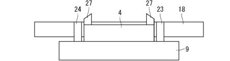
- FIG. 24 is a side view of FIG. 22.
- the second guide mechanism 27 is provided at two locations, one on the left and one on the right, at the upper front end of the guide mechanism 4, and at two locations, one on the left and one on the right, at the upper rear end of the guide mechanism 4. If there is an error between the guide mechanism 4 and the front connecting fitting 23 and the rear connecting fitting 24, when the guide mechanism 4 is raised, the front connecting fitting 23 and the rear connecting fitting 24 first come into contact with the second guide mechanism 27, and then, as the guide mechanism 4 rises, the front connecting fitting 23 and the rear connecting fitting 24 are guided by the second guide mechanism 27, and finally the guide mechanism 4 is positioned between the front connecting fitting 23 and the rear connecting fitting 24.
- the second guide mechanism 27 may be configured integrally with the guide mechanism 4.
- a second guide mechanism 27 is provided at each of the upper front and upper rear ends in the fore-and-aft direction of the center frame groove 25. This increases the allowable position error between the guide mechanism 4 and the front connecting fitting 23 and the rear connecting fitting 24 before the guide mechanism 4 rises, so that the guide mechanism 4 can be positioned between the front connecting fitting 23 and the rear connecting fitting 24 without using a high-performance sensor. In other words, a transport device that is less expensive than the first embodiment can be realized.
- the second guide mechanism 27 may be provided at each of the front and rear sides of the guide mechanism 4 in the front-rear direction.
- the second induction mechanism 27 may be configured integrally with the guide mechanism 4.
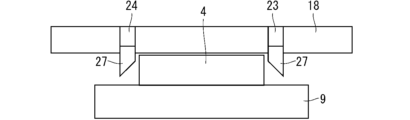
- the second guide mechanism 27 may be provided on each of the front connecting fitting 23 and the rear connecting fitting 24 .
- the second guide mechanism 27 may be configured integrally with each of the front connecting fitting 23 and the rear connecting fitting 24.
- the configuration shown in FIG. 26 may be combined with the configurations shown in FIGS. 22 to 24. Also, the configuration shown in FIG. 26 may be combined with the configuration shown in FIG. 25.
- the cart has been described as having the front connecting fittings 23 and the rear connecting fittings 24 attached to the center frame 18 so as to protrude in a direction different from the extending direction of the center frame 18 .
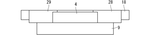
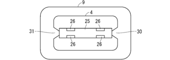
- the cart has a front connecting fitting 28 and a rear connecting fitting 29 with a wedge-shaped structure (see, for example, Figures 27 and 28), and the guide mechanism 4 has a front notch 30 and a rear notch 31 (see, for example, Figure 31).
- the rest of the configuration and operation of the transport device 8 and the cart are the same as in the second embodiment, so detailed explanations will be omitted here.
- Figure 27 is an external view showing the state in which the transport device and cart according to embodiment 4 are fitted together.
- Figure 28 is a plan view showing the state in which the center frame groove 25 and the center frame 18 are fitted together.
- Figure 29 is a cross-sectional view taken along D1-D1 in Figure 28.
- Figure 30 is a side view of Figure 28. Note that the transport device shown in Figure 27 is a simplified version of an actual transport device.
- the front connecting fitting 28 has a wedge-shaped structure with the base of the triangular prism fixed to the front frame 16.
- the front connecting fitting 28 has a wedge-shaped structure in which the other end on the rear frame side is narrower in width in a plan view than the other end on the front frame 16 side, and the other end overlaps the center frame 18 in a plan view.
- the rear connecting fitting 29 has a wedge-shaped structure with the base of the triangular prism fixed to the rear frame 17. Specifically, the rear connecting fitting 29 has a wedge-shaped structure in which the width of its one end on the front frame 16 side is narrower than the width of its other end on the rear frame 17 side in a plan view, and the other end overlaps the center frame 18 in a plan view.
- Figure 31 is a plan view showing an example of the guide mechanism 4. As shown in Figure 31, the guide mechanism 4 has a front notch 30 that can be fitted with the front connecting fitting 28, and a rear notch 31 that can be fitted with the rear connecting fitting 29.
- a dual-purpose guide mechanism 32 may be provided in each of the front cutout 30 and the rear cutout 31 of the guide mechanism 4. Two dual-purpose guide mechanisms 32 are provided in the front cutout 30, and two dual-purpose guide mechanisms 32 are provided in the rear cutout 31.
- a first guide mechanism 26 may be further provided in the center frame groove 25.
- a first guide mechanism 26 may be further provided in the center frame groove 25.
- the functions of the control unit 7 and the communication unit 12 in the conveying device 8 shown in Fig. 2 are realized by a processing circuit. That is, the conveying device 8 includes a processing circuit for controlling the device driving unit 3 and the guide mechanism driving unit 5 so that the center frame 18 fits into the center frame groove 25 based on the detection results of the sensor group 6, and for communicating with an instruction center 15 provided outside the conveying device 8.
- the processing circuit may be dedicated hardware, or may be a processor (also called a CPU, central processing unit, processing unit, arithmetic unit, microprocessor, microcomputer, or DSP (Digital Signal Processor)) that executes a program stored in a memory.
- a processor also called a CPU, central processing unit, processing unit, arithmetic unit, microprocessor, microcomputer, or DSP (Digital Signal Processor)
- the processing circuit 33 may be, for example, a single circuit, a composite circuit, a programmed processor, a parallel programmed processor, an ASIC (Application Specific Integrated Circuit), an FPGA (Field Programmable Gate Array), or a combination of these.
- Each function of the control unit 7 and the communication unit 12 may be realized by a processing circuit 33, or each function may be realized together by a single processing circuit 33.
- each function of the control unit 7 and the communication unit 12 is realized by software, firmware, or a combination of software and firmware.
- the software or firmware is written as a program and stored in the memory 35.
- the processor 34 realizes each function by reading and executing the program recorded in the memory 35. That is, the conveying device 8 has a memory 35 for storing a program that results in the execution of a step of controlling the device drive unit 3 and the guide mechanism drive unit 5 so that the center frame 18 fits into the center frame groove 25 based on the detection result of the sensor group 6, and a step of communicating with an instruction center 15 provided outside the conveying device 8. It can also be said that these programs cause a computer to execute the procedures or methods of the control unit 7 and the communication unit 12.
- memory may be, for example, non-volatile or volatile semiconductor memory such as RAM (Random Access Memory), ROM (Read Only Memory), flash memory, EPROM (Erasable Programmable Read Only Memory), EEPROM (Electrically Erasable Programmable Read Only Memory), magnetic disk, flexible disk, optical disk, compact disk, DVD (Digital Versatile Disc), etc., or any storage medium that will be used in the future.
- RAM Random Access Memory
- ROM Read Only Memory
- flash memory such as EPROM (Erasable Programmable Read Only Memory), EEPROM (Electrically Erasable Programmable Read Only Memory), magnetic disk, flexible disk, optical disk, compact disk, DVD (Digital Versatile Disc), etc., or any storage medium that will be used in the future.
- control unit 7 and communication unit 12 may be realized by dedicated hardware, and other functions may be realized by software or firmware.
Landscapes
- Engineering & Computer Science (AREA)
- Mechanical Engineering (AREA)
- Handcart (AREA)
- Control Of Position, Course, Altitude, Or Attitude Of Moving Bodies (AREA)
Priority Applications (2)
| Application Number | Priority Date | Filing Date | Title |
|---|---|---|---|
| JP2024562470A JP7618115B2 (ja) | 2022-12-07 | 2022-12-07 | 搬送装置および搬送方法 |
| PCT/JP2022/045079 WO2024121968A1 (ja) | 2022-12-07 | 2022-12-07 | 搬送装置および搬送方法 |
Applications Claiming Priority (1)
| Application Number | Priority Date | Filing Date | Title |
|---|---|---|---|
| PCT/JP2022/045079 WO2024121968A1 (ja) | 2022-12-07 | 2022-12-07 | 搬送装置および搬送方法 |
Publications (1)
| Publication Number | Publication Date |
|---|---|
| WO2024121968A1 true WO2024121968A1 (ja) | 2024-06-13 |
Family
ID=91378956
Family Applications (1)
| Application Number | Title | Priority Date | Filing Date |
|---|---|---|---|
| PCT/JP2022/045079 Ceased WO2024121968A1 (ja) | 2022-12-07 | 2022-12-07 | 搬送装置および搬送方法 |
Country Status (2)
| Country | Link |
|---|---|
| JP (1) | JP7618115B2 (https=) |
| WO (1) | WO2024121968A1 (https=) |
Citations (8)
| Publication number | Priority date | Publication date | Assignee | Title |
|---|---|---|---|---|
| JPS6223203U (https=) * | 1985-07-29 | 1987-02-12 | ||
| JPS63148231U (https=) * | 1987-03-20 | 1988-09-29 | ||
| WO2005105620A1 (ja) * | 2004-04-30 | 2005-11-10 | Yuyama Mfg. Co., Ltd. | カート搬送装置 |
| US9073736B1 (en) * | 2013-09-25 | 2015-07-07 | Amazon Technologies, Inc. | Enhanced inventory holder |
| JP2018034964A (ja) * | 2016-08-31 | 2018-03-08 | 株式会社日立製作所 | 多段棚搬送システム及び多段棚搬送方法 |
| CN108382779A (zh) * | 2018-04-28 | 2018-08-10 | 上海托华机器人有限公司 | 一种智能仓储分拣系统及货架、agv |
| JP2018151328A (ja) * | 2017-03-14 | 2018-09-27 | 株式会社日立製作所 | 経路決定装置、経路決定方法及び経路決定プログラム |
| JP2019162954A (ja) * | 2018-03-20 | 2019-09-26 | 株式会社イシダ | 無人搬送車 |
-
2022
- 2022-12-07 WO PCT/JP2022/045079 patent/WO2024121968A1/ja not_active Ceased
- 2022-12-07 JP JP2024562470A patent/JP7618115B2/ja active Active
Patent Citations (8)
| Publication number | Priority date | Publication date | Assignee | Title |
|---|---|---|---|---|
| JPS6223203U (https=) * | 1985-07-29 | 1987-02-12 | ||
| JPS63148231U (https=) * | 1987-03-20 | 1988-09-29 | ||
| WO2005105620A1 (ja) * | 2004-04-30 | 2005-11-10 | Yuyama Mfg. Co., Ltd. | カート搬送装置 |
| US9073736B1 (en) * | 2013-09-25 | 2015-07-07 | Amazon Technologies, Inc. | Enhanced inventory holder |
| JP2018034964A (ja) * | 2016-08-31 | 2018-03-08 | 株式会社日立製作所 | 多段棚搬送システム及び多段棚搬送方法 |
| JP2018151328A (ja) * | 2017-03-14 | 2018-09-27 | 株式会社日立製作所 | 経路決定装置、経路決定方法及び経路決定プログラム |
| JP2019162954A (ja) * | 2018-03-20 | 2019-09-26 | 株式会社イシダ | 無人搬送車 |
| CN108382779A (zh) * | 2018-04-28 | 2018-08-10 | 上海托华机器人有限公司 | 一种智能仓储分拣系统及货架、agv |
Also Published As
| Publication number | Publication date |
|---|---|
| JPWO2024121968A1 (https=) | 2024-06-13 |
| JP7618115B2 (ja) | 2025-01-20 |
Similar Documents
| Publication | Publication Date | Title |
|---|---|---|
| US10486901B2 (en) | Method and system for transporting inventory items | |
| JP2011518740A (ja) | リフト車両用フローティングフォーク | |
| CA2748398C (en) | Method and system for transporting inventory items | |
| JP2007126254A (ja) | 搬送装置 | |
| JP2009292582A (ja) | スタッカクレーン | |
| CN103529061A (zh) | 车载式辐射检查系统 | |
| JP2019006567A (ja) | 物品搬送設備、及び、物品搬送車 | |
| TW201435531A (zh) | 搬運系統 | |
| JP7618115B2 (ja) | 搬送装置および搬送方法 | |
| JP2019197349A (ja) | 無人搬送車のスピンターンにおける停止位置制御システム、及び無人搬送車のスピンターンにおける回転角度制御方法 | |
| US20220363475A1 (en) | Transport Vehicle | |
| US11643272B2 (en) | Article transport vehicle | |
| KR102689643B1 (ko) | 자율주행 로봇 | |
| JP7612104B2 (ja) | 搬送装置および搬送方法 | |
| JP2012150588A (ja) | 有軌道台車システム | |
| JP7724967B2 (ja) | 搬送装置および搬送方法 | |
| JP5372422B2 (ja) | 搬送台車用ワーク移載装置 | |
| JP2021046287A (ja) | 走行車システム | |
| JP7839073B2 (ja) | 搬送台車 | |
| JPS61216442A (ja) | キヤリアの搬送装置 | |
| JP4314780B2 (ja) | 無人搬送車システム | |
| JP2024128225A (ja) | 搬送台車 | |
| JP2019148127A (ja) | 機械式格納装置 | |
| US20240427354A1 (en) | Data processing device, mobile body system, mobile body, data processing method, and storage medium | |
| JP7768183B2 (ja) | 搬送システム |
Legal Events
| Date | Code | Title | Description |
|---|---|---|---|
| 121 | Ep: the epo has been informed by wipo that ep was designated in this application |
Ref document number: 22967819 Country of ref document: EP Kind code of ref document: A1 |
|
| WWE | Wipo information: entry into national phase |
Ref document number: 2024562470 Country of ref document: JP |
|
| NENP | Non-entry into the national phase |
Ref country code: DE |
|
| 122 | Ep: pct application non-entry in european phase |
Ref document number: 22967819 Country of ref document: EP Kind code of ref document: A1 |