WO2024121921A1 - 測定装置 - Google Patents
測定装置 Download PDFInfo
- Publication number
- WO2024121921A1 WO2024121921A1 PCT/JP2022/044849 JP2022044849W WO2024121921A1 WO 2024121921 A1 WO2024121921 A1 WO 2024121921A1 JP 2022044849 W JP2022044849 W JP 2022044849W WO 2024121921 A1 WO2024121921 A1 WO 2024121921A1
- Authority
- WO
- WIPO (PCT)
- Prior art keywords
- component
- pair
- terminals
- measuring device
- measuring
- Prior art date
- Legal status (The legal status is an assumption and is not a legal conclusion. Google has not performed a legal analysis and makes no representation as to the accuracy of the status listed.)
- Ceased
Links
Images




Classifications
-
- G—PHYSICS
- G01—MEASURING; TESTING
- G01R—MEASURING ELECTRIC VARIABLES; MEASURING MAGNETIC VARIABLES
- G01R31/00—Arrangements for testing electric properties; Arrangements for locating electric faults; Arrangements for electrical testing characterised by what is being tested not provided for elsewhere
-
- G—PHYSICS
- G01—MEASURING; TESTING
- G01R—MEASURING ELECTRIC VARIABLES; MEASURING MAGNETIC VARIABLES
- G01R31/00—Arrangements for testing electric properties; Arrangements for locating electric faults; Arrangements for electrical testing characterised by what is being tested not provided for elsewhere
- G01R31/28—Testing of electronic circuits, e.g. by signal tracer
Definitions
- This disclosure relates to a measuring device that measures the electrical characteristics of electronic components.
- an electronic component held on a conductive holder is gripped by the opposing surfaces of a pair of probes, and the electrical characteristics of the electronic component are measured with the holder retracted from the electronic component.
- the objective of this disclosure is to accurately measure the electrical characteristics of electronic components.
- each of a pair of probes that holds an electronic component includes two terminals. Because the component is held well by the two terminals, the electrical characteristics of the component can be measured well.
- FIG. 1 is a perspective view of a measurement device according to an embodiment of the present disclosure.
- FIG. 2 is a perspective view of a mounting machine including the measuring device.
- FIG. 2 is a cross-sectional view of a main part of the measuring device.
- FIG. 2 is a plan view of the measuring device.
- FIG. 4 is a circuit diagram of an air supply unit included in the measuring device.
- FIG. 2 is a perspective view of a part to be measured by the measuring device.
- 2 is a conceptual diagram showing the periphery of a suction nozzle included in the placement machine.
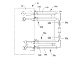
- FIG. FIG. 2 is a diagram conceptually illustrating an electrical characteristic measuring circuit of the measuring device.
- FIG. 2 is a conceptual diagram showing a coaxial cable constituting the electrical characteristic measuring circuit.
- FIG. 1 is a perspective view of a measurement device according to an embodiment of the present disclosure.
- FIG. 2 is a perspective view of a mounting machine including the measuring device.
- FIG. 2 is a cross-section
- FIG. 2 is a plan view conceptually showing a main part of the measuring device.
- FIG. 2 is a side view conceptually showing the main part.
- FIG. 2 is a block diagram conceptually illustrating the periphery of a control device of the measuring device.
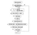
- 5 is a flowchart showing an electrical characteristic acquisition program stored in a storage unit of the control device.
- the measuring device can be called an electrical characteristic acquisition device.
- the mounting machine shown in FIG. 2 mounts components onto a circuit board, and includes a main body 2, a circuit board conveying and holding device 4, a component supplying device 6, a head moving device 8, and the like.
- the circuit board transport and holding device 4 transports and holds the circuit board P (hereinafter, abbreviated as board P) in a horizontal position.
- the transport direction of the board P is the x direction
- the width direction of the board P is the y direction
- the thickness direction of the board P is the z direction.
- the y direction and the z direction are the front-rear and up-down directions of the mounting machine, respectively. These x direction, y direction, and z direction are perpendicular to each other.
- the component supply device 6 supplies electronic components (hereinafter, abbreviated as components) s to be mounted on the board P, and includes a plurality of tape feeders 14 and the like.
- the head moving device 8 holds the mounting head 16 and moves it in the x, y, and z directions.
- the mounting head 16 has a suction nozzle 18 that picks up and holds the components s.
- the suction nozzle 18 holds the component s by negative pressure.
- a negative pressure source 20 and a positive pressure source 21 are connected to an air pipe 19 provided on the main body via solenoid valves 20v and 21v, respectively, which serve as selection devices.
- the negative pressure source 20 is connected to the air pipe 19
- the positive pressure source 21 is connected to the air pipe 19
- the held component s is released.
- air is discharged from the air pipe 19 by connecting the positive pressure source 21 to the air pipe 19.
- Reference numeral 22 denotes a camera.
- the camera 22 captures an image of the component s held by the suction nozzle 18, and based on the image captured by the camera 22, it is determined whether or not the component s is to be mounted on the circuit board P.
- Reference numeral 24 denotes a measuring device.
- the measuring device 24 measures the electrical characteristics of the component s. Examples of the electrical characteristics of the component s include L (inductance), C (capacitance), R (resistance), X (reactance), Z' (impedance), etc., and the measuring device 24 measures one or more of these.
- the measuring device 24 is mounted on the mounting machine and is provided on the main body of the circuit board conveying and holding device 4 via a storage box 26.
- a disposal passage 28 is provided between the storage box 26 and the measuring device 24, and the components s whose electrical characteristics have been measured are stored in the storage box 26 via the disposal passage 28.
- the measuring device 24 is provided on the storage box 26 so that its height can be adjusted.
- a base portion 30 is engaged with the storage box 26 so that it can be raised and lowered, and a measuring table 29 is detachably held on the base portion 30.
- the base portion 30 and the measuring table 29 can be raised and lowered as a unit.
- the measuring table 29 and the base portion 30 are provided with through holes 29a, 30a, respectively, which can communicate with the disposal passage 28 (see FIGS. 3 and 4).
- the measuring device 24 includes the measuring table 29 and base portion 30, a holding table 32 capable of holding the component s, a pair of measuring elements 37 consisting of a stator 34 and a mover 36, a holding table moving device 40 for moving the holding table 32, a mover moving device 41 as an approaching/separating device for moving the mover 36 toward/away from the stator 34, a measuring portion 42 (see FIG. 4), etc.
- the component s has electrodes sp1, sp2 at both ends as shown in FIG. 6, and the length between the pair of electrodes sp1, sp2 is Ap.
- the portion s can be, for example, a square chip.
- the holding table 32 includes a component placement section 44 and a placement section holder 46 that holds the component placement section 44.
- a V-shaped groove 44c is formed in the component placement section 44, and the component s is placed on the V-shaped groove 44c.
- the part of the component placement section 44 where the V-shaped groove 44c is formed (which can be called the component holding section 65) is an insulating section made of a low-dielectric material.
- a low-dielectric material usually has a relative dielectric constant of 0.3 or less, and examples of such materials include organic plastic materials such as epoxy resin and ceramic materials such as glass. Since the component holding section 65 is made of a low-dielectric material, the component s held by the component holding section 65 is less likely to become charged. In addition, since the component holding section 65 is an insulating section and not made of a conductive material, the electrical characteristics of the component can be measured while it is held by the component holding section 65.
- a cover part 62 extending in the vertical direction is attached to the holding table 32.
- the cover part 62 moves integrally with the holding table 32 as it moves.
- the stator 34 is held by a stator holder 55, which is fixed to the measurement table 29.
- the mover 36 is held movably as one unit by the mover holder 56, which is provided movably relative to the measurement table 29.
- the mover 36 can move toward and away from the stator 34, and the pair of measuring probes 37 can move toward and away from each other.
- the stator 34 and the mover 36 each include a body 34h, 36h with opposing surfaces 34f, 36f that face each other, and a terminal pair 52, 54 held by each of the bodies 34h, 36h, respectively.
- the terminal pair 52 includes two terminals 52a, 52b
- the terminal pair 54 includes two terminals 54a, 54b.
- One end of a coaxial cable 58a, 58b is connected to the base end of each of the terminals 52a, 52b via a bracket.
- the tip end of each of the terminals 52a, 52b protrudes from the opposing surface 34f toward the mover 36.
- the base end of each of the terminals 54a, 54b is connected to one end of a coaxial cable 60a, 60b via a bracket, and the tip end protrudes from the opposing surface 36f toward the stator 34.
- each of these terminals 52a, 52b, 54a, and 54b is in the form of a plate extending in one direction, and is provided in such a manner that the one direction corresponds to the approach/separation direction (y direction) of the pair of probes 37, the width direction corresponds to the up-down direction (z direction), and the thickness direction corresponds to the width direction (x direction).
- the tip of each of terminals 52a, 52b and terminals 54a, 54b is wedge-shaped, and as shown in Figures 8, 10, and 11, one side in the thickness direction is a flat portion, and the other side is an inclined surface that is inclined in a direction in which the tip side is thinner than the base end side.
- each of the two terminals 52a, 52b and terminals 54a, 54b is provided with the flat portions facing each other and the inclined portions located on the opposite sides. This allows the spacing between terminals 52a and 52b and between terminals 54a and 54b to be narrowed, allowing them to be positioned near the center of the V-groove 44c.
- the terminals 52a, 52b, 54a, 54b each have a tapered tip. Furthermore, the bottom of the terminals 52a, 52b, 54a, 54b in the vertical direction reaches the bottom surface of the V-groove 44c. As a result, even if the part s to be measured is small, the part s can be satisfactorily held by the pair of terminals 52, 54.
- the terminals 52a, 52b, 54a, 54b are made of a hardened material, such as a cemented carbide alloy. This makes it possible to suppress deterioration of the pair of terminal pairs 52, 54.
- the part s is held by the pair of probes 34, 36 with the tips of the terminals 52a, 52b, 54a, 54b slightly piercing the electrode portions sp1, sp2 of the part s. Therefore, even if the part s is small, it can be held well by the pair of terminal pairs 52, 54.
- the tips of terminals 52a, 52b, 54a, and 54b can be wedge-shaped to form a needle shape, but the shape is not important.
- a pair of guard members 34g, 36g are provided on the pair of bodies 34h, 36h, protruding in the direction of approaching each other.
- the guard members 34g, 36g are made of a conductive material.
- the length Ag of each of the guard members 34g, 36g from the opposing surfaces 34f, 36f in the approach/separation direction (y direction) is longer than the length Ac of the terminals 52a, 52b and terminals 54a, 54b from the opposing surfaces 34f, 36f. Therefore, when the pair of probes 37 approach each other without the part s being interposed, the guard members 34g, 36g come into contact with each other, and the tips of the terminal pairs 52, 54 are protected.
- the length Ag of the guard members 34g, 36g is set to a length that allows the pair of terminal pairs 52, 54 to grip the part s, even if the part s to be measured is small.
- the amount of protrusion (Ag-Ac) of the guard members 34g and 36g from the tips of the terminals 52a, 52b, 54a, and 54b is greater than 0 and less than 1/2 the length Ap (see Figure 6) of the smallest part s to be measured.
- an air passage 70 is formed in a member on the stator side (e.g., one or more of the upper part of the stator 34, the part of the stator holder 55 above the stator 34, and the measurement table 29), and is connected to air cylinders 72, 74 as fluid pressure cylinders, an air source 78, etc.
- An opening 70a of the air passage 70 is formed facing diagonally downward.
- An ionizer 76 is also provided in the air passage 70. The ionizer 76 ionizes the air by generating a corona discharge. The ionized air released from the opening 70a is irradiated onto the part s held by the pair of terminals 52, 54.
- the air cylinder 72 is the drive source for the holder moving device 40, and the mounting portion holder 46 is connected to the piston rod 72p of the air cylinder 72.
- An electromagnetic valve device 80 is provided between the two air chambers 72a, 72b of the air cylinder 72, the air source 78, the air passage 70, and the silencer (atmosphere). The movement of the mounting portion holder 46 (holding table 32) and the like are controlled by controlling the electromagnetic valve device 80.
- the air cylinder 74 is the driving source for the movable member moving device 41, and the movable member holder 56 is connected to the piston rod 74p.
- the air chambers 74a and 74b of the air cylinder 74 are connected to an air source 78, air passage 70, and silencer (atmosphere) via an electromagnetic valve device 82.
- the movement of the movable member holder 56 (movable member 36) is controlled by controlling the electromagnetic valve device 82.
- an electromagnetic on-off valve 83 is provided between the air source 78 and the air passage 70.
- the electromagnetic on-off valve 83 is a normally closed valve, and the air source 78 and the air passage 70 are not directly connected to each other.
- the electromagnetic on-off valve 83 is switched to an open state, and air ionized by the ionizer 76 is discharged from the opening 70a.
- the air cylinders 72, 74, the air source 78, the ionizer 76, the air passage 70, the electromagnetic valve devices 80, 82, the electromagnetic on-off valve 83, etc. form an air supply unit 85.
- the holding table 32 and the movable member holding body 56 are provided with a pair of guide rods 86, 87 extending in the y direction, and the movable member holding body 56 and the measurement table 29 are provided with a pair of guide rods 88, 89 extending in the y direction.
- These guide rods 86, 87, 88, 89 allow the holding table 32 and the movable member 36 to move relative to each other in the y direction with respect to the measurement table 29, and allow the holding table 32 and the movable member 36 to move relative to each other in the y direction.
- a stopper 92 is provided on the stator side of the mover holder 56, and a stopper 90 is provided on the portion of the measurement table 29 that holds the stator holder 55.
- the stopper 92 determines the approach limit between the mover holder 56 and the holding table 32 (mounting section holder 46), and the stopper 90 determines the approach limit between the stator 34 (measurement table 29) and the holding table 32.
- the coaxial cables 58a, 58b, 60a, and 60b described above have the same structure, and include an inner conductor 140, an insulator (dielectric) 142, an outer conductor 144, a protective coating 146, and the like, which are arranged coaxially, as shown in Fig. 9.
- the provision of the outer conductor 144 suppresses leakage of the transmitted signal to the outside.
- one end of the inner conductor 140 is connected to the terminals 52a, 52b, 54a, and 54b, respectively, and the other end is connected to the measuring unit 42, respectively.
- the coaxial cables 58a and 58b form a coaxial cable section 58
- the coaxial cables 60a and 60b form a coaxial cable section 60
- An electrical characteristic measuring circuit 61 is formed by the coaxial cable sections 58 and 60, the terminal pairs 52 and 54, the measuring section 42, etc.
- the other end of the coaxial cable 60a is connected to the Hc terminal and is connected to an AC power source.
- the output of the AC power source is supplied to the inner conductor 140 of the coaxial cable 58a and returned via the outer conductor 144.
- the other end of the coaxial cable 60b is connected to the Hp terminal and is connected to a voltage sensor.
- the potential difference between the inner conductor 140 and the outer conductor 144 is detected as a voltage value applied to the component s.
- the other end of the coaxial cable 58a is connected to the Lc terminal and then to a current sensor.
- the current flowing between the inner conductor 140 and the outer conductor 144 is obtained as the current value flowing through the component s.
- the potential difference of a resistor with a resistance value Rx (not shown) provided between the inner conductor 140 and the outer conductor 144 is obtained, and the current flowing through the resistor is obtained based on the potential difference and the resistance value Rx.
- the other end of the coaxial cable 58b is connected to the Lp terminal.
- the potential difference between the inner conductor 140 and the outer conductor 144 is detected, and components of the measurement unit 42 (not shown, such as an oscillator) are controlled so that the detected potential difference becomes zero.
- the current flowing through the resistor and the current flowing through the component s become the same, and the current flowing through the resistor obtained at the terminal Lc in this state becomes the current value flowing through the component s.
- 150 indicates an identical potential section. By providing the identical potential section 150, the outer conductors 144 of the coaxial cable sections 58 and 60 are at the same ground potential, making it possible to reduce noise and stably measure the electrical characteristics of the component s.
- coaxial cables 58a, 58b, 60a, 60b are connected using the four-terminal pair connection method, and the electrical characteristics of component s are measured using the automatic balancing bridge method.
- the current flowing through component s and the voltage applied to component s are measured using separate circuits, and the currents flowing through the inner conductor 140 and the outer conductor 144 are set in opposite directions. This makes it possible to suppress the generation of magnetic flux in each of the inner conductor 140 and the outer conductor 144, and allows the current and voltage flowing through component s to be measured with high accuracy.
- the electrical characteristic measuring circuit 61 electrical disturbances may occur in parts other than the component s, which may affect the measured values of the electrical characteristics of the component s measured by the measuring unit 42.
- a short correction value and an open correction value are calculated, and the measured values are corrected to obtain the final electrical characteristics of the component s, which are closer to the true electrical characteristics.
- the short correction value is measured when the guard members 34g and 36g are in contact with each other.
- the placement machine includes a control device 200.
- the control device 200 includes a controller 202, which is mainly a computer, and multiple drive circuits 204.
- the controller 202 includes an execution unit 210, a storage unit 212, an input/output unit 214, etc., to which the board transport/holding device 4, the component supplying device 6, and the head moving device 8 are each connected via the drive circuits 204, and the solenoid valve devices 80, 82 of the holding table moving device 40 and the movable element moving device 41 are also connected.
- a measurement unit 42, a display 216, a movable element position sensor 218, a holding table position sensor 220, a nozzle height sensor 222, etc. are connected.
- the electrical characteristics of the component s are measured by executing an electrical characteristics measurement program represented by the flow chart of FIG.
- the solenoid valve devices 80, 82 and the solenoid on-off valve 83 are controlled based on output signals from a moving element position sensor 218 and a holding table position sensor 220.
- the measurement results can be displayed on a display 216.
- the measuring device 24 is always in the initial position.
- the moving element 36 is in the retracted end position, and the holding table 32 is in the advanced end position.
- step 1 it is determined whether or not a command to measure the electrical characteristics of part s has been issued. For example, when a changeover is being performed, if a command to measure the electrical characteristics of part s has been issued, the determination is YES.
- the open correction value and short correction value are acquired, and the measured open correction value and short correction value are stored in the memory unit 212.
- the mounting head 16 equipped with the suction nozzle 18 holding the component s is moved, and the suction nozzle 18 is lowered above the V-groove 44c, releasing the component s and placing it in the V-groove 44c.
- the mover 36 is advanced by control of the solenoid valve device 82, and the component s is gripped by the terminal pair 54 of the mover 36 and the terminal pair 52 of the stator 34. It is assumed that the terminal pairs 52, 54 are in contact with the electrode portions sp1, sp2 of the component s and are in a state of being embedded therein.
- the parts are de-electrified.
- the electromagnetic valve 83 is switched to an open state, and air supplied from the air source 78 is discharged from the opening 70a via the ionizer 76 and the air passage 70.
- the discharged ions are irradiated onto the parts s, etc., thereby de-electrifying the parts s.
- the electrical characteristics (e.g., impedance) of component s are measured.
- the final impedance Zdut of component s is determined based on the impedance measurement value Zm described above and the open correction value and short correction value determined in S2.
- the final impedance Zdut can be displayed on the display 216, or compared with a default value and the comparison result can be displayed on the display 216.
- the movable element 36 is retracted and the holding table 32 is also retracted.
- the space between the pair of probes 37 is enclosed by the cover portion 62.
- the movable element 36 is retracted, air is discharged from the opening 70a, but the air is prevented from diffusing inside the cover portion 62 and flows in a vortex shape. This makes it possible to separate the component s from the terminals 52a, 52b, 54a, and 54b, and the component s can be dropped.
- the component is stored in the component storage portion 26 via the disposal passage 28.
- the holding table 32 is advanced and returned to its initial position.
- the component s is securely held by the pair of terminals 52, 54. This improves the accuracy of measuring the electrical characteristics of the component s.
- the tip of each of the four terminals 52a, 52b, 54a, 54b is generally wedge-shaped, the generation of an oxide film is suppressed at the contact portion between the terminals 52a, 52b, 54a, 54b and the component s, as compared to the opposing surfaces 34f, 36f. Therefore, the deterioration of the reliability of the measured values of the electrical characteristics of the component s can be suppressed as compared to the case where the component s is held by a pair of opposing surfaces 34f, 36f.
- a step can be provided in which the suction nozzle 18 detaches the component s from the pair of terminal pairs 52, 54.
- the component s is often held with the tips of the terminal pairs 52, 54 piercing the electrodes sp1, sp2. For this reason, there may be cases where the component s cannot be detached from the terminal pairs 52, 54 due to the air supplied from the opening 70a.
- the suction nozzle 18 can eject air onto the component s from a second direction (e.g., the z direction, which is the up-down direction) that is perpendicular to the first direction (y direction) that is the gripping direction of the terminal pairs 52, 54, or can contact the component s from the z direction. This allows the component s to be satisfactorily detached from the pair of terminal pairs 52, 54.
- the bodies 34h, 36h of the pair of probes 37 can also be made of resin, which can reduce weight and costs.
- the measuring device 24 may be provided with a dedicated static elimination unit for eliminating static electricity from the component s, or a dedicated component removal unit for removing the component s from the terminal pair 52, 54 after the electrical characteristics have been measured. However, it is not essential to provide a static elimination unit or a component removal unit.
- the pair of terminal pairs 52, 54 can also be provided so as to be movable relative to the main bodies 34h, 36h, respectively.
- the tip portions of the pair of terminal pairs 52, 54 can be retracted into the main bodies 34h, 36h so as not to protrude from the opposing surfaces 34f, 36f. This allows the component s to be detached from the terminals 52a, 52b, 54a, 54b.
- the tip portions of the terminals 52a, 52b, 54a, 54b can be protected.
- the component detachment portion is constituted by a mechanism that allows the pair of terminal pairs 52, 54 to be movable relative to the main bodies 34h, 36h.
- the short correction value acquisition unit is made up of the electrical characteristic measuring circuit 61, the pair of guard members 34g, 36g, the part of the control device 200 that stores S2, the part that executes it, etc.
- the static elimination unit is made up of the air supply unit 85 including the ionizer 76, etc.
- the component removal unit is made up of the suction nozzle 18 of the head moving device 8, etc., or the suction nozzle 18 of the head moving device 8, the positive pressure source 21, etc.
- the component holding unit 65 corresponds to the insulator part and the low dielectric constant part.
- a measuring device for measuring electrical characteristics of an electronic component in a state where the component is held by a pair of probes comprising: A measuring device in which each of the pair of probes includes two terminals capable of contacting the component.
- Each of the four terminals may be plate-shaped or rod-shaped. Furthermore, each of the four terminals may have at least a tip portion that becomes thinner as it approaches the tip, for example, a wedge shape. A wedge shape also includes a needle shape. Furthermore, by making the tip portion wedge-shaped, each of the two terminals can be made to be able to approach each other at the tip portions.
- a measuring device in which the four terminals, including the two terminals each, are connected by a four-terminal pair connection method or a four-terminal connection method.
- the four-terminal connection method is a connection method that separates the current signal path and the voltage signal path.
- the four-terminal connection method is a connection method in which the measurement current flows only through the inner conductor, while the four-terminal pair connection method is a connection method in which the measurement current flows through the inner conductor of the coaxial cable and an equal but opposite current flows through the outer conductor.
- Each of the pair of probes includes a body having opposing surfaces facing each other, The two terminals are provided so as to protrude from the opposing surfaces in directions approaching each other,
- the measuring device according to any one of items (1) to (3) includes a pair of guard members provided on each of the pair of opposing surfaces, each protruding from each of the two terminals.
- the measuring device further comprising a short correction value acquisition unit that acquires a short correction value when the pair of guard members are in contact with each other.
- the short correction value is obtained when the tips of a pair of guard members are in contact with each other.
- the tips of the guard members protrude beyond the tips of the terminals.
- the measuring device includes a component holding unit that holds the component, the pair of probes grip the component held by the component holder, The measuring device according to any one of claims (1) to (5), wherein the component holding portion includes an insulating portion made of an insulating material.
- the insulating portion can be made of a low dielectric constant material.
- the measuring device further comprising a charge removal unit that removes charge from the component held in the component holder.
- the measuring device is provided in a mounting machine that mounts the components on a circuit board,
- the static elimination unit may be provided in the measuring device or in the mounting machine.
- the static elimination unit may be configured to eliminate static electricity from a component that is held in the component holding unit and is gripped by a pair of terminal pairs, each of which has two terminals.
- a measuring device in which the static electricity removal unit includes an ionizer that irradiates the part with ions.
- the measuring device is provided in a mounting machine that mounts the components on a circuit board, The measuring device according to any one of claims (1) to (9), wherein the mounting machine includes a component removal unit that removes the component from a pair of terminal pairs each having two terminals after measuring the electrical characteristics.
- the part removal unit can be, for example, an airbrush.
- the part removal unit can also include an air supply unit provided in the measuring device, or can include a suction nozzle of the mounting machine, etc.
- a measuring device according to claim (10) or (11), in which the part removal section includes an air supply section that applies air to the part held by the pair of terminals.
- the component is held by the pair of terminals from a first direction,
- a measuring device according to any one of items (10) to (13), in which the part release portion includes a part contact portion that contacts the part held by the pair of terminals.
- the component contact portion can contact the component from a direction perpendicular to the first direction.
- the placement machine includes a holding head that holds and moves the component, the holding head includes a suction nozzle as a component holder that suctions and holds the component,
- the measuring device according to any one of (1) to (14), wherein the suction nozzle detaches the component from the pair of terminals each having two terminals after the electrical characteristics are measured.
- the suction nozzle functions as an air supply unit that applies air to the parts, and as a part contact unit that comes into contact with the parts to detach them.
- the measuring device further comprises: an approaching/separating device for moving the pair of probes closer to/separating them from each other; a support table for supporting the component; A measuring device according to any one of claims (1) to (15), in which the electrical characteristics of the component are measured while the component is held on a holding table and the approaching/separating device brings the pair of probes closer to each other so that each of the two terminals contacts and holds the component.
Landscapes
- Physics & Mathematics (AREA)
- General Physics & Mathematics (AREA)
- Engineering & Computer Science (AREA)
- General Engineering & Computer Science (AREA)
- Testing Of Individual Semiconductor Devices (AREA)
Priority Applications (3)
| Application Number | Priority Date | Filing Date | Title |
|---|---|---|---|
| PCT/JP2022/044849 WO2024121921A1 (ja) | 2022-12-06 | 2022-12-06 | 測定装置 |
| CN202280102083.8A CN120188055A (zh) | 2022-12-06 | 2022-12-06 | 测定装置 |
| JP2024562427A JPWO2024121921A1 (https=) | 2022-12-06 | 2022-12-06 |
Applications Claiming Priority (1)
| Application Number | Priority Date | Filing Date | Title |
|---|---|---|---|
| PCT/JP2022/044849 WO2024121921A1 (ja) | 2022-12-06 | 2022-12-06 | 測定装置 |
Publications (1)
| Publication Number | Publication Date |
|---|---|
| WO2024121921A1 true WO2024121921A1 (ja) | 2024-06-13 |
Family
ID=91378837
Family Applications (1)
| Application Number | Title | Priority Date | Filing Date |
|---|---|---|---|
| PCT/JP2022/044849 Ceased WO2024121921A1 (ja) | 2022-12-06 | 2022-12-06 | 測定装置 |
Country Status (3)
| Country | Link |
|---|---|
| JP (1) | JPWO2024121921A1 (https=) |
| CN (1) | CN120188055A (https=) |
| WO (1) | WO2024121921A1 (https=) |
Citations (9)
| Publication number | Priority date | Publication date | Assignee | Title |
|---|---|---|---|---|
| JPS6350767A (ja) * | 1986-08-21 | 1988-03-03 | Matsushita Electric Ind Co Ltd | 電子部品の位置規正装置 |
| JP2002232200A (ja) * | 2001-02-07 | 2002-08-16 | Pioneer Electronic Corp | 電子部品装着装置 |
| JP2003337153A (ja) * | 2002-05-20 | 2003-11-28 | Murata Mfg Co Ltd | チップ部品の特性測定方法および特性測定装置 |
| JP2004170360A (ja) * | 2002-11-22 | 2004-06-17 | Kanto Tsusoku Kiki Kk | 積層型プローブ及び接触子 |
| US20080074125A1 (en) * | 2006-09-25 | 2008-03-27 | Ceramic Component Technologies, Inc. | Handheld electronic test probe assembly |
| JP2008241653A (ja) * | 2007-03-29 | 2008-10-09 | Nec Electronics Corp | 半導体検査装置 |
| JP2010019855A (ja) * | 2004-06-16 | 2010-01-28 | Ueno Seiki Kk | 電子部品測定装置及び電子部品測定方法 |
| JP2012173003A (ja) * | 2011-02-17 | 2012-09-10 | Ueno Seiki Kk | 電子部品測定装置 |
| JP2017106856A (ja) * | 2015-12-11 | 2017-06-15 | 上野精機株式会社 | 電気特性テスト装置 |
-
2022
- 2022-12-06 CN CN202280102083.8A patent/CN120188055A/zh active Pending
- 2022-12-06 WO PCT/JP2022/044849 patent/WO2024121921A1/ja not_active Ceased
- 2022-12-06 JP JP2024562427A patent/JPWO2024121921A1/ja active Pending
Patent Citations (9)
| Publication number | Priority date | Publication date | Assignee | Title |
|---|---|---|---|---|
| JPS6350767A (ja) * | 1986-08-21 | 1988-03-03 | Matsushita Electric Ind Co Ltd | 電子部品の位置規正装置 |
| JP2002232200A (ja) * | 2001-02-07 | 2002-08-16 | Pioneer Electronic Corp | 電子部品装着装置 |
| JP2003337153A (ja) * | 2002-05-20 | 2003-11-28 | Murata Mfg Co Ltd | チップ部品の特性測定方法および特性測定装置 |
| JP2004170360A (ja) * | 2002-11-22 | 2004-06-17 | Kanto Tsusoku Kiki Kk | 積層型プローブ及び接触子 |
| JP2010019855A (ja) * | 2004-06-16 | 2010-01-28 | Ueno Seiki Kk | 電子部品測定装置及び電子部品測定方法 |
| US20080074125A1 (en) * | 2006-09-25 | 2008-03-27 | Ceramic Component Technologies, Inc. | Handheld electronic test probe assembly |
| JP2008241653A (ja) * | 2007-03-29 | 2008-10-09 | Nec Electronics Corp | 半導体検査装置 |
| JP2012173003A (ja) * | 2011-02-17 | 2012-09-10 | Ueno Seiki Kk | 電子部品測定装置 |
| JP2017106856A (ja) * | 2015-12-11 | 2017-06-15 | 上野精機株式会社 | 電気特性テスト装置 |
Also Published As
| Publication number | Publication date |
|---|---|
| JPWO2024121921A1 (https=) | 2024-06-13 |
| CN120188055A (zh) | 2025-06-20 |
Similar Documents
| Publication | Publication Date | Title |
|---|---|---|
| CN107852856B (zh) | 检查装置 | |
| JP6607719B2 (ja) | 検査装置 | |
| US11483953B2 (en) | Measurement device and measurement method | |
| WO2024121921A1 (ja) | 測定装置 | |
| JP7404072B2 (ja) | 測定装置 | |
| US20250052794A1 (en) | Electrical characteristic acquiring device | |
| WO2017009986A1 (ja) | 検査装置 | |
| JP7326277B2 (ja) | 測定装置 | |
| WO2017037887A1 (ja) | 検査装置 | |
| JP6568733B2 (ja) | 検査装置 | |
| JP7035256B2 (ja) | 装着機 | |
| JP6771256B2 (ja) | 検査装置 | |
| WO2021074943A1 (ja) | 測定装置、実装機、クランプ状態取得装置 | |
| JP6852127B2 (ja) | 検査装置および検査方法 | |
| JP7013599B2 (ja) | 装着機 | |
| JP2022169619A (ja) | 電子部品装着機 | |
| JP6780085B2 (ja) | 装着機、測定方法 | |
| JP2026023630A (ja) | 電気的特性取得装置 | |
| JP7504134B2 (ja) | 実装機 | |
| JP6912620B2 (ja) | 検査装置 | |
| JP7164924B2 (ja) | 電子部品装着機および検査方法 | |
| JP2022040316A (ja) | 装着機 | |
| JP7804030B2 (ja) | 装着機 | |
| WO2025052504A1 (ja) | 測定装置、装着機 | |
| WO2024201700A1 (ja) | 測定装置 |
Legal Events
| Date | Code | Title | Description |
|---|---|---|---|
| 121 | Ep: the epo has been informed by wipo that ep was designated in this application |
Ref document number: 22967775 Country of ref document: EP Kind code of ref document: A1 |
|
| WWE | Wipo information: entry into national phase |
Ref document number: 2024562427 Country of ref document: JP |
|
| WWE | Wipo information: entry into national phase |
Ref document number: CN2022801020838 Country of ref document: CN Ref document number: 202280102083.8 Country of ref document: CN |
|
| WWP | Wipo information: published in national office |
Ref document number: 202280102083.8 Country of ref document: CN |
|
| NENP | Non-entry into the national phase |
Ref country code: DE |
|
| 122 | Ep: pct application non-entry in european phase |
Ref document number: 22967775 Country of ref document: EP Kind code of ref document: A1 |