WO2024116285A1 - ロボットシステムのシミュレーション装置 - Google Patents
ロボットシステムのシミュレーション装置 Download PDFInfo
- Publication number
- WO2024116285A1 WO2024116285A1 PCT/JP2022/044016 JP2022044016W WO2024116285A1 WO 2024116285 A1 WO2024116285 A1 WO 2024116285A1 JP 2022044016 W JP2022044016 W JP 2022044016W WO 2024116285 A1 WO2024116285 A1 WO 2024116285A1
- Authority
- WO
- WIPO (PCT)
- Prior art keywords
- robot
- robot system
- moving object
- processor
- simulation
- Prior art date
- Legal status (The legal status is an assumption and is not a legal conclusion. Google has not performed a legal analysis and makes no representation as to the accuracy of the status listed.)
- Ceased
Links
Images

Classifications
-
- B—PERFORMING OPERATIONS; TRANSPORTING
- B25—HAND TOOLS; PORTABLE POWER-DRIVEN TOOLS; MANIPULATORS
- B25J—MANIPULATORS; CHAMBERS PROVIDED WITH MANIPULATION DEVICES
- B25J9/00—Program-controlled manipulators
- B25J9/16—Program controls
- B25J9/1656—Program controls characterised by programming, planning systems for manipulators
- B25J9/1671—Program controls characterised by programming, planning systems for manipulators characterised by simulation, either to verify existing program or to create and verify new program, CAD/CAM oriented, graphic oriented programming systems
Definitions
- This disclosure relates to a simulation device for a robot system.
- a moving object such as an unmanned guided vehicle performing a task different from that of the robot system may enter or remain within the operating range of the robot.
- the robot's operation is slowed down or stopped, and the cycle time of the robot system increases. Therefore, even if there is a moving object other than the originally planned moving object, such as a collaborating worker, within the operating range of the robot, it is desirable to keep the cycle time of the robot system within a desired time.
- One aspect of the present disclosure is a simulation device for a robot system that includes at least one robot, at least one sensor that detects a moving object within a detection area around the robot, and at least one control device that controls the robot, and when the sensor detects the moving object, the control device corresponding to the sensor slows down or stops the operation of the robot, the simulation device for a robot system that includes at least one processor, at least one memory, and an input device, the memory stores layout information of the robot system, the input device accepts input of movement information of the moving object, the processor executes a simulation of the operation of the robot system based on the layout information and the movement information, and calculates a delay time of the operation for when the moving object is not detected within the detection area.
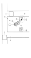
- FIG. 1 is a plan view showing a layout of a robot system to which a simulation device according to an embodiment of the present disclosure is applied.
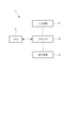
- FIG. 1 is a block diagram showing a simulation device according to an embodiment of the present disclosure.
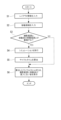
- 3 is a flowchart illustrating a simulation method using the simulation device of FIG. 2 .
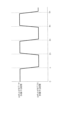
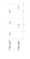
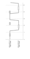
- 4 is a time chart showing the operation of the robot in the robot system of FIG. 1 when no moving object is present within the shooting range. 3 is a time chart showing movement information input to the simulation device of FIG. 2 . 4 is a time chart showing the operation of the robot in the robot system of FIG. 1 taking into consideration the entry of a moving object into a shooting range.
- FIG. 2 is a plan view showing a modified example of the layout of the robot system in FIG. 1 .
- a simulation device 1 for a robot system 10 will be described below with reference to the drawings. First, a robot system 10 to which the simulation device 1 of the present embodiment is applied will be described.
- the robot system 10 includes at least one robot 20, at least one camera (sensor) 31, 32 that captures images of the surroundings of the robot 20, and at least one control device 40.
- FIG. 1 shows only a portion of the robot system 10, and shows one robot 20, two cameras 31, 32, and one control device 40 provided in the robot system 10.
- the robot 20 is, for example, a six-axis articulated robot.
- the robot 20 is installed between two work tables WT1 and WT2 that are spaced apart in the horizontal direction.
- the robot 20 also performs the task of picking up, one by one, a number of work pieces W that are randomly piled up on the work table WT1, and moving them to the work table WT2.
- Cameras 31 and 32 are, for example, two-dimensional cameras that capture two-dimensional images. Cameras 31 and 32 are also installed facing downward above work tables WT1 and WT2, and are provided with cone-shaped shooting ranges (detection areas) s1 and s2 at positions that include work tables WT1 and WT2, respectively. This allows cameras 31 and 32 to capture two-dimensional images of shooting ranges s1 and s2 at a predetermined frame rate.
- the control device 40 includes at least one processor (not shown) and memories such as RAM and ROM (not shown), and is connected to the robot 20 and the cameras 31 and 32 .
- the memory of the control device 40 stores an operation program for operating the robot 20.
- the processor of the control device 40 executes the operation program stored in the memory to operate each axis of the robot 20 and cause the robot 20 to perform a desired task.
- the control device 40 also transmits an image capture command to one of the cameras 31, 32 that corresponds to the posture of the robot 20, to capture images at a predetermined frame rate.
- the control device 40 causes the camera 31, 32 on the side toward which the wrist of the robot 20 is facing to capture a two-dimensional image, and receives the two-dimensional image.
- the control device 40 also processes the received two-dimensional image to extract all moving objects contained in the two-dimensional image.
- the control device 40 then excludes the robot 20 (including tools attached to the robot 20, etc.) from the extracted moving objects, and determines whether any moving object A other than the robot 20 is included. If all of the extracted moving objects include a moving object A other than the robot 20, the control device 40 slows down or stops the movement of each axis of the robot 20. In other words, the cycle time of the robot system 10 is delayed by the time that the movement of the robot 20 is slowed down or stopped.
- the simulation device 1 is realized by a computer such as a personal computer.
- the simulation device 1 includes an input device 2, a memory 3 such as a ROM and a RAM, at least one processor 4 such as a CPU, and a display device 5.
- a memory 3 such as a ROM and a RAM
- processor 4 such as a CPU
- a display device 5 the simulation device 1 includes an input device 2, a memory 3 such as a ROM and a RAM, at least one processor 4 such as a CPU, and a display device 5.
- the input device 2 is composed of, for example, a keyboard, a touch panel, an operation panel, and a serial interface such as USB.
- the input device 2 also accepts movement information of at least one moving object A input by an operator who operates the simulation device 1.
- the movement information is, for example, information such as the movement path of the moving object A and the time at each position on the movement path based on the start time of the operation program of the robot system 10.
- the memory 3 stores layout information of the robot system 10 in the factory.
- the layout information is, for example, information on the positions and sizes of each component of the robot system 10, the work tables WT1, WT2, and the shooting ranges s1, s2, and information on the position and shape of the passage P near the robot 20. All of this layout information is converted into a three-dimensional model and stored in the memory 3.
- the memory 3 also stores a simulation program and an operation program for the robot system 10.
- the simulation program is executed by the processor 4, which will be described later, and the operation program for the robot system 10 is executed in a virtual space on the computer.
- the memory 3 stores the ideal cycle time of the robot system 10, that is, the cycle time when the moving object A does not enter the shooting ranges s1 and s2 and the operation of the robot 20 does not slow down or stop.
- the memory 3 also stores the movement information of the moving object A input to the input device 2.
- the processor 4 retrieves the movement information of the moving object A stored in the memory 3 and the layout information of the robot system 10, and determines whether the movement path of the moving object A overlaps with the shooting ranges s1 and s2 based on both pieces of information.
- the processor 4 executes the simulation program stored in the memory 3 to place the robot system 10, a passage P in its vicinity, and a moving body A moving on the passage P in a virtual space on the computer.
- the processor 4 uses the movement information and layout information retrieved from the memory 3 to execute a simulation of the operation program of the robot system 10 and the operation of the moving body A placed in the virtual space.
- the processor 4 calculates the cycle time of the operation program taking into account the operation delay of the robot 20 caused by the moving body A entering the shooting ranges s1 and s2.
- the display device 5 is composed of a liquid crystal display or the like.
- the processor 4 causes the display device 5 to display the layout of the robot system 10 and its surroundings, and the shooting ranges s1 and s2, superimposed on each other, based on the layout information.
- the processor 4 also causes the display device 5 to display, together with the layout information displayed, a delay time calculated by, for example, comparing the calculated cycle time of the operating program with an ideal cycle time stored in the memory 3.
- an operator operating the simulation device 1 inputs layout information of the robot system 10 into the input device 2 (step S1). This causes a three-dimensional model indicating the passage P near the robot 20 and the relative positional relationship of each component of the robot system 10 and the shooting ranges s1 and s2 with respect to the passage P to be stored in the memory 3.
- the operator also inputs the operation program of the robot system 10 and a previously calculated ideal cycle time of the operation program into the input device 2 along with the layout information, and stores them in the memory 3.
- the example shown in FIG. 4 is an example of a time chart of an operation program input to the input device 2, in which the wrist tip of the robot 20 moves back and forth between the work tables WT1 and WT2 at n second intervals, causing the robot 20 to perform a desired task.
- the operator inputs the movement path of each moving object A and the time at each position on the movement path into the input device 2 as movement information for all moving objects A moving along the passage P near the robot 20 (step S2).
- the input movement information is stored in the memory 3.
- processor 4 retrieves the layout information and movement information stored in memory 3 and compares the two pieces of information. Processor 4 then determines whether the movement path of moving object A contained in the movement information overlaps with the shooting ranges s1, s2 contained in the layout information (step S3). If processor 4 determines that the movement path overlaps with shooting ranges s1, s2, it extracts the time period of overlap and stores it in memory 3. That is, memory 3 stores the time period during which moving object A is present in each shooting range s1, s2 relative to the elapsed time from the start time of the operation program of the robot system 10, as shown in FIG. 5.
- the processor 4 executes the simulation program stored in the memory 3 (step S4).
- the processor 4 sets the robot system 10, the passage P, and the moving body A in a virtual space on the computer based on the layout information read from the memory 3.
- the processor 4 operates the robot system 10 in the virtual space according to the operation program, and operates the moving body A based on the movement information.
- the robot 20 when the robot 20 is working with its wrist tip facing the workbench WT1, if the moving object A enters the shooting range s1, the robot 20 stops or decelerates. Therefore, as shown in Figures 4 to 6, the operation program is delayed by the time during which the operation of the robot 20 stops or decelerates while the robot 20 is working on the workbench WT1 side. Similarly, when the robot 20 is working with its wrist tip facing the workbench WT2 and a moving body A enters the shooting range s2, the robot 20 stops or decelerates, and the operation program is delayed by the time the robot 20 stops or decelerates.
- the processor 4 calculates the cycle time of the operation program delayed due to the entry of the moving object A into the shooting ranges s1 and s2 (step S5).
- the processor 4 also calculates the delay time of the operation program by comparing the cycle time calculated from the simulation results with the ideal cycle time stored in the memory 3. This delay time is calculated separately into the delay time during work on the work table WT1 side of the robot 20 and the delay time during work on the work table WT2 side.
- the processor 4 causes the display device 5 to display the calculated cycle time and delay time together with the layout information stored in the memory 3 (step S6).
- the display device 5 displays each delay time calculated by the processor 4 due to the moving body A entering the shooting ranges s1 and s2 in association with the shooting ranges s1 and s2 displayed based on the layout information.
- step S3 determines that the movement path of the moving object A does not overlap with the shooting ranges s1 and s2 (step S3). Then, the processor 4 causes the display device 5 to display a message indicating that the moving object A has not entered the shooting ranges s1 and s2 (step S6).
- the operator can check whether there is a possibility of a delay in the cycle time of the robot system 10 by checking the display device 5. Furthermore, if there is a possibility of a delay in the cycle time, the operator can check the delay time of the operation program of the robot system 10 calculated from the simulation results, which is displayed on the display device 5.
- the operator can determine whether or not the cycle time exceeds the desired time based on the display on the display device 5. If the cycle time exceeds the desired time, the layout of the robot system 10 can be changed so that the delay time of the operation program is reduced.
- the operator can distinguish and understand the delay time caused by moving body A entering shooting range s1 from the delay time caused by moving body A entering shooting range s2 by looking at the display device 5. Therefore, of the two delay times, the one that has the greater impact on the cycle time can be given priority for shortening, and the layout of the robot system 10 can be changed more efficiently.
- the entire robot system 10 may be moved away from the aisle P adjacent to the workbench WT1.
- the movement route of the moving object A and the time at each position on the movement route are input to the input device 2 as movement information, but this is not limited to this.
- this information may be input to the input device 2 as movement information.
- the processor 4 multiplies the number of times the moving object A enters the shooting ranges s1 and s2 by the staying time per entry, thereby calculating the cumulative staying time per unit time of the moving object A in the shooting range s1 and the cumulative staying time per unit time of the moving object A in the shooting range s2.
- the processor 4 may execute a simulation of the operation program and calculate the cycle time taking into account a delay time proportional to the accumulated stay time of the moving body A in each shooting range s1, s2.
- the frequency with which moving body A enters the shooting ranges s1 and s2 per unit time and the duration of time spent there per entry are known as levels divided into multiple stages, these levels may be used as movement information.
- a score is assigned to each level according to the magnitude of that level.
- the cumulative duration of stay of moving body A in each shooting range s1 and s2 can also be estimated by multiplying and adding up the score assigned to the level of frequency of entry and the score assigned to the level of duration of stay.
- the layout of the robot system 10 is changed to shorten the delay time of the operation program.
- the delay time may be shortened by changing the operation program of the robot system 10 without changing the layout of the robot system 10.
- the delay time may be shortened by changing the movement method of the moving body A that moves through the passage P, that is, the movement path or movement speed of the moving body A, etc.
- the display device 5 may display the time period during which the operation of the robot 20 is stopped, based on the simulation results, in correspondence with the time of the operation program. This allows the operator to know the timing of the running operation program at which the operation of the robot 20 will be stopped. Therefore, the operator can change the operation program of the robot system 10 or the movement method of the moving body A so that the moving body A enters the shooting ranges s1 and s2 to avoid that timing.
- the robot system 10 to which the simulation device 1 is applied has two shooting ranges s1 and s2, but the number of shooting ranges may be one or three or more.
- the simulation device 1 is applied to a robot system 10 in which the cameras 31 and 32 are installed above the work tables WT1 and WT2, respectively.
- the simulation device 1 may be applied to a robot system 10 equipped with a single camera (sensor) 33 that is fixed to the wrist of the robot 20 and has an imaging range (detection area) s3 around the tip of the wrist, as shown in FIG. 7.
- the robot system 10 to which the simulation device 1 is applied has the cameras 31 and 32 disposed above the work tables WT1 and WT2, respectively. Therefore, the image capturing ranges s1 and s2 expand in a cone shape from above to below the work tables WT1 and WT2, respectively. In other words, it is necessary to take into consideration that the image capturing ranges s1 and s2 for detecting the moving object A change in the height direction.
- the cameras 31 and 32 of the robot system 10 to which the simulation device 1 is applied may each be configured by arranging a plurality of line sensors, such as area sensors, adjacent to each other.
- the size of the shooting ranges s1 and s2 is constant in the height direction. Therefore, the simulation device 1 can determine the overlap between the moving body A and the shooting ranges s1 and s2 in two dimensions. Therefore, even if the layout information input to the input device 2 is a two-dimensional model, the accuracy of the simulation of the operation program is not reduced.
- a simulation device 1 for a robot system 10 comprising at least one robot 20, at least one sensor 31, 32, 33 for detecting moving objects within detection areas s1, s2, s3 around the robot 20, and at least one control device 40 for controlling the robot 20, wherein when the sensors 31, 32, 33 detect the moving object A, the control device 40 corresponding to the sensor 31, 32, 33 slows down or stops the operation of the robot 20, the simulation device 1 for a robot system 10 comprising at least one processor 4, at least one memory 3, and an input device 2, wherein the memory 3 stores layout information of the robot system 10, the input device 2 accepts input of movement information of the moving object A, the processor 4 executes a simulation of the operation of the robot system 10 based on the layout information and the movement information, and calculates a delay time of the operation for a case where the moving object A is not detected within the detection areas s1, s2, s3.
- the simulation device 1 for a robot system 10 according to claim 1, wherein the processor 4 calculates a cycle time of the operation of the robot system 10.
- the simulation device 1 for the robot system 10 described in Appendix 1 or Appendix 2 is provided with a display device 5 that displays the layout information, and the processor 4 causes the display device to display areas s1, s2, and s3 in which the moving body A is detected by the sensors 31, 32, and 33 based on the movement information and the layout information, superimposed on the layout information.
- (Appendix 4) A simulation device 1 for a robot system 10 described in any one of Supplementary Note 1 to Supplementary Note 3, wherein the movement information includes a movement path of the moving body A and a time when the moving body A is present at each position on the movement path.
- (Appendix 5) A simulation device 1 for a robot system 10 described in any one of Appendix 1 to Appendix 3, wherein the movement information includes the number of times per unit time that the moving body A enters the detection areas s1, s2, and s3 and the residence time per entry.
- the processor 4 determines whether or not there is a possibility of the moving body A entering the detection areas s1, s2, s3 based on the movement information input to the input device 2, and if it determines that there is a possibility that the moving body A will enter the detection areas s1, s2, s3, the processor 4 executes the simulation.
Landscapes
- Engineering & Computer Science (AREA)
- Robotics (AREA)
- Mechanical Engineering (AREA)
- Manipulator (AREA)
Priority Applications (5)
| Application Number | Priority Date | Filing Date | Title |
|---|---|---|---|
| CN202280099856.1A CN120202097A (zh) | 2022-11-29 | 2022-11-29 | 机器人系统的模拟装置 |
| DE112022007574.0T DE112022007574T5 (de) | 2022-11-29 | 2022-11-29 | Robotersystemsimulationsvorrichtung |
| PCT/JP2022/044016 WO2024116285A1 (ja) | 2022-11-29 | 2022-11-29 | ロボットシステムのシミュレーション装置 |
| JP2024561024A JPWO2024116285A1 (cg-RX-API-DMAC7.html) | 2022-11-29 | 2022-11-29 | |
| TW112144162A TW202423636A (zh) | 2022-11-29 | 2023-11-15 | 機器人系統的模擬裝置 |
Applications Claiming Priority (1)
| Application Number | Priority Date | Filing Date | Title |
|---|---|---|---|
| PCT/JP2022/044016 WO2024116285A1 (ja) | 2022-11-29 | 2022-11-29 | ロボットシステムのシミュレーション装置 |
Publications (1)
| Publication Number | Publication Date |
|---|---|
| WO2024116285A1 true WO2024116285A1 (ja) | 2024-06-06 |
Family
ID=91323337
Family Applications (1)
| Application Number | Title | Priority Date | Filing Date |
|---|---|---|---|
| PCT/JP2022/044016 Ceased WO2024116285A1 (ja) | 2022-11-29 | 2022-11-29 | ロボットシステムのシミュレーション装置 |
Country Status (5)
| Country | Link |
|---|---|
| JP (1) | JPWO2024116285A1 (cg-RX-API-DMAC7.html) |
| CN (1) | CN120202097A (cg-RX-API-DMAC7.html) |
| DE (1) | DE112022007574T5 (cg-RX-API-DMAC7.html) |
| TW (1) | TW202423636A (cg-RX-API-DMAC7.html) |
| WO (1) | WO2024116285A1 (cg-RX-API-DMAC7.html) |
Citations (3)
| Publication number | Priority date | Publication date | Assignee | Title |
|---|---|---|---|---|
| JP2004280635A (ja) * | 2003-03-18 | 2004-10-07 | Honda Motor Co Ltd | シミュレーション装置,シミュレーション方法及びシミュレーションプログラム |
| JP2017024113A (ja) * | 2015-07-21 | 2017-02-02 | ファナック株式会社 | 人間協調型ロボットシステムのロボットシミュレーション装置 |
| WO2020174663A1 (ja) * | 2019-02-28 | 2020-09-03 | 日本電気株式会社 | 搬送経路設計装置、搬送経路設計方法、及び、記録媒体 |
Family Cites Families (3)
| Publication number | Priority date | Publication date | Assignee | Title |
|---|---|---|---|---|
| JP3927482B2 (ja) * | 2002-10-30 | 2007-06-06 | 本田技研工業株式会社 | シミュレーション装置 |
| CN112936268A (zh) * | 2021-01-30 | 2021-06-11 | 埃夫特智能装备股份有限公司 | 一种协作机器人安全控制系统 |
| JP7098080B1 (ja) * | 2021-09-08 | 2022-07-08 | 三菱電機株式会社 | ロボット制御装置 |
-
2022
- 2022-11-29 JP JP2024561024A patent/JPWO2024116285A1/ja active Pending
- 2022-11-29 CN CN202280099856.1A patent/CN120202097A/zh active Pending
- 2022-11-29 DE DE112022007574.0T patent/DE112022007574T5/de active Pending
- 2022-11-29 WO PCT/JP2022/044016 patent/WO2024116285A1/ja not_active Ceased
-
2023
- 2023-11-15 TW TW112144162A patent/TW202423636A/zh unknown
Patent Citations (3)
| Publication number | Priority date | Publication date | Assignee | Title |
|---|---|---|---|---|
| JP2004280635A (ja) * | 2003-03-18 | 2004-10-07 | Honda Motor Co Ltd | シミュレーション装置,シミュレーション方法及びシミュレーションプログラム |
| JP2017024113A (ja) * | 2015-07-21 | 2017-02-02 | ファナック株式会社 | 人間協調型ロボットシステムのロボットシミュレーション装置 |
| WO2020174663A1 (ja) * | 2019-02-28 | 2020-09-03 | 日本電気株式会社 | 搬送経路設計装置、搬送経路設計方法、及び、記録媒体 |
Also Published As
| Publication number | Publication date |
|---|---|
| JPWO2024116285A1 (cg-RX-API-DMAC7.html) | 2024-06-06 |
| TW202423636A (zh) | 2024-06-16 |
| CN120202097A (zh) | 2025-06-24 |
| DE112022007574T5 (de) | 2025-06-05 |
Similar Documents
| Publication | Publication Date | Title |
|---|---|---|
| JP5523386B2 (ja) | 衝突回避装置 | |
| JP7058126B2 (ja) | ロボット制御装置および自動組立システム | |
| EP3950239B1 (en) | Control system, control method, and control unit | |
| CN110394779B (zh) | 机器人的模拟装置 | |
| US10353383B2 (en) | Simulator, simulation method, and simulation program | |
| US8855823B2 (en) | Robot controller, simple installation-type robot, and method of controlling simple installation-type robot | |
| JP7154815B2 (ja) | 情報処理装置、制御方法、ロボットシステム、コンピュータプログラム、及び記憶媒体 | |
| US9569568B2 (en) | Robot simulation system which simulates takeout process of workpiece | |
| JP5887526B2 (ja) | 作業検知システム | |
| US11919171B2 (en) | Robot controller | |
| EP1769890A2 (en) | Robot simulation device | |
| JP2010120139A (ja) | 産業用ロボットの安全制御装置 | |
| US11235463B2 (en) | Robot system and robot control method for cooperative work with human | |
| JP7156397B2 (ja) | 制御装置 | |
| JP2018062026A (ja) | ロボットの速度や加速度を制限する機能を備えたロボット制御装置 | |
| CN118715492A (zh) | 示教辅助装置、作业系统、示教辅助方法及示教辅助程序 | |
| JP7448651B2 (ja) | オフライン教示装置および動作プログラム生成方法 | |
| JP7729067B2 (ja) | 領域設定装置、ラック、制御システム、領域設定方法及びプログラム | |
| CN120202097A (zh) | 机器人系统的模拟装置 | |
| JP7383999B2 (ja) | 協調作業システム、解析装置および解析プログラム | |
| WO2022190538A1 (ja) | 情報処理装置および情報処理方法、並びにプログラム | |
| US20260084312A1 (en) | Picking System | |
| US20250353170A1 (en) | Robot system and robot control device | |
| JP2793695B2 (ja) | 物体の認識制御方法 | |
| EP4370286B1 (en) | Teaching a robot system using hand gesture control and visual-inertial-odometry |
Legal Events
| Date | Code | Title | Description |
|---|---|---|---|
| 121 | Ep: the epo has been informed by wipo that ep was designated in this application |
Ref document number: 22967119 Country of ref document: EP Kind code of ref document: A1 |
|
| WWE | Wipo information: entry into national phase |
Ref document number: 202280099856.1 Country of ref document: CN |
|
| WWE | Wipo information: entry into national phase |
Ref document number: 112022007574 Country of ref document: DE |
|
| WWE | Wipo information: entry into national phase |
Ref document number: 2024561024 Country of ref document: JP |
|
| WWP | Wipo information: published in national office |
Ref document number: 112022007574 Country of ref document: DE |
|
| WWP | Wipo information: published in national office |
Ref document number: 202280099856.1 Country of ref document: CN |
|
| 122 | Ep: pct application non-entry in european phase |
Ref document number: 22967119 Country of ref document: EP Kind code of ref document: A1 |