WO2024111561A1 - ケーブル束、ケーブル束の製造方法、及び、ケーブル束の製造装置 - Google Patents
ケーブル束、ケーブル束の製造方法、及び、ケーブル束の製造装置 Download PDFInfo
- Publication number
- WO2024111561A1 WO2024111561A1 PCT/JP2023/041683 JP2023041683W WO2024111561A1 WO 2024111561 A1 WO2024111561 A1 WO 2024111561A1 JP 2023041683 W JP2023041683 W JP 2023041683W WO 2024111561 A1 WO2024111561 A1 WO 2024111561A1
- Authority
- WO
- WIPO (PCT)
- Prior art keywords
- cable
- bundle
- unit
- loop
- cable bundle
- Prior art date
- Legal status (The legal status is an assumption and is not a legal conclusion. Google has not performed a legal analysis and makes no representation as to the accuracy of the status listed.)
- Ceased
Links
Images




Classifications
-
- B—PERFORMING OPERATIONS; TRANSPORTING
- B65—CONVEYING; PACKING; STORING; HANDLING THIN OR FILAMENTARY MATERIAL
- B65H—HANDLING THIN OR FILAMENTARY MATERIAL, e.g. SHEETS, WEBS, CABLES
- B65H55/00—Wound packages of filamentary material
- B65H55/04—Wound packages of filamentary material characterised by method of winding
-
- B—PERFORMING OPERATIONS; TRANSPORTING
- B65—CONVEYING; PACKING; STORING; HANDLING THIN OR FILAMENTARY MATERIAL
- B65H—HANDLING THIN OR FILAMENTARY MATERIAL, e.g. SHEETS, WEBS, CABLES
- B65H54/00—Winding, coiling, or depositing filamentary material
- B65H54/56—Winding of hanks or skeins
-
- B—PERFORMING OPERATIONS; TRANSPORTING
- B65—CONVEYING; PACKING; STORING; HANDLING THIN OR FILAMENTARY MATERIAL
- B65H—HANDLING THIN OR FILAMENTARY MATERIAL, e.g. SHEETS, WEBS, CABLES
- B65H54/00—Winding, coiling, or depositing filamentary material
- B65H54/70—Other constructional features of yarn-winding machines
-
- H—ELECTRICITY
- H02—GENERATION; CONVERSION OR DISTRIBUTION OF ELECTRIC POWER
- H02G—INSTALLATION OF ELECTRIC CABLES OR LINES, OR OF COMBINED OPTICAL AND ELECTRIC CABLES OR LINES
- H02G1/00—Methods or apparatus specially adapted for installing, maintaining, repairing or dismantling electric cables or lines
- H02G1/06—Methods or apparatus specially adapted for installing, maintaining, repairing or dismantling electric cables or lines for laying cables, e.g. laying apparatus on vehicle
-
- B—PERFORMING OPERATIONS; TRANSPORTING
- B65—CONVEYING; PACKING; STORING; HANDLING THIN OR FILAMENTARY MATERIAL
- B65H—HANDLING THIN OR FILAMENTARY MATERIAL, e.g. SHEETS, WEBS, CABLES
- B65H2701/00—Handled material; Storage means
- B65H2701/30—Handled filamentary material
- B65H2701/32—Optical fibres or optical cables
Definitions
- the present invention relates to a cable bundle, a method for manufacturing a cable bundle, and an apparatus for manufacturing a cable bundle.
- a known method of winding a cable is the so-called “figure-of-eight winding,” in which the cable is alternately twisted clockwise and counterclockwise to create loops while winding the cable (see, for example, Patent Document 1).
- the spiral twist that occurs when the first loop (second loop) is unwound cancels the twist that was imparted when the second loop (first loop) was made, so no twist occurs in the cable.
- the problem that the present invention aims to solve is to provide a cable bundle that can prevent the rings from floating up, a method for manufacturing the cable bundle, and an apparatus for manufacturing the cable bundle.
- Aspect 1 of the present invention is a cable bundle with a wound cable, the cable bundle comprising a plurality of unit bundles stacked in a second direction perpendicular to a first direction which is the circumferential direction of the cable bundle, each of the unit bundles comprising first and second loops stacked in the second direction, the first and second loops being interconnected at a connection such that when the unit bundle is opened, an eight-shaped loop is formed comprising the first and second loops, and the connection parts of the unit bundles adjacent to each other in the second direction are offset in the first direction.
- Aspect 2 of the present invention may be a cable bundle according to aspect 1, in which the connection portions of the unit bundles adjacent to each other in the second direction are offset in the first direction within a range of 90 degrees to 270 degrees.
- Aspect 3 of the present invention may be a cable bundle according to aspect 1 or 2, in which each of the unit bundles is formed by folding an eight-shaped loop having the first and second loops at the connection portion.
- Aspect 4 of the present invention is a cable bundle according to any one of aspects 1 to 3, in which the cable bundle has an intermediate portion interposed between the unit bundles to connect the unit bundles, and the intermediate portion may be a cable bundle wound along the first direction such that the connection portions of the unit bundles adjacent in the second direction are shifted in the first direction.
- a fifth aspect of the present invention may be a cable bundle according to the fourth aspect, in which the intermediate portion is wound along the first direction such that the connection portions of the unit bundles adjacent to each other in the second direction are shifted in the first direction within a range of 90 degrees to 270 degrees.
- a sixth aspect of the present invention may be a cable bundle according to the fourth or fifth aspect, in which the intermediate portion has a length that is 1/4 to 3/4 of the circumference of the first or second loop connected to the intermediate portion.
- Aspect 7 of the present invention is a cable bundle according to any one of aspects 1 to 6, in which the multiple unit bundles include a first unit bundle, a second unit bundle overlapped on the first unit bundle, and a third unit bundle overlapped on the second unit bundle, and the cable bundle includes a first intermediate portion interposed between the first unit bundle and the second unit bundle and connecting the first unit bundle and the second unit bundle, and a second intermediate portion interposed between the second unit bundle and the third unit bundle and connecting the second unit bundle and the third unit bundle, the first and second intermediate portions being wound along the first direction, and the first intermediate portion and the second intermediate portion being offset in the first direction.
- Aspect 8 of the present invention is a cable bundle according to any one of aspects 1 to 7, in which the cable bundle includes an intermediate portion interposed between the unit bundles to connect the unit bundles and wound along the first direction, and the cable is twisted in a direction opposite to the twist caused by the intermediate portion when the cable is unwound.
- a ninth aspect of the present invention may be a cable bundle according to the eighth aspect, in which the number of twisting turns imparted to the cables is equal to or less than a value obtained by dividing the total length of the intermediate portions by the average circumference of the cable bundle.
- Aspect 10 of the present invention is a cable bundle according to any one of aspects 1 to 7, in which the connection portion is a portion of the cable between a first intersection of the first loop and a second intersection of the second loop, and the cable bundle may be wound along the first direction.
- Aspect 11 of the present invention may be a cable bundle according to aspect 10, in which the connection portions of the unit bundles adjacent to each other in the second direction and an intermediate portion connecting the unit bundles form one loop along the first direction.
- Aspect 12 of the present invention may be a cable bundle according to any one of aspects 1 to 11, in which the first loop is formed by winding the cable in a forward winding or a reverse winding opposite to the forward winding, and the second loop is formed by winding the cable in the reverse winding or the forward winding.
- Aspect 13 of the present invention may be a cable bundle according to any one of aspects 1 to 12, in which the unit bundle is formed so that twisting due to the unit bundle does not occur in the cable when the cable is unwound.
- Aspect 14 of the present invention is a method for manufacturing a cable bundle having a wound cable, comprising: a first step of forming a plurality of unit bundles, each of which has a first loop and a second loop that are connected at a connection portion and overlapped with each other; and a second step of overlapping the plurality of unit bundles such that the connection portions are offset from each other in a first direction, which is the circumferential direction of the cable bundle, and the first and second loops are connected to each other at the connection portions such that an eight-shaped loop is formed with the first and second loops when the unit bundle is opened.
- Aspect 15 of the present invention may be the method for manufacturing a cable bundle of aspect 14, in which the first step includes forming a plurality of third loops, each of which includes the first loop and the second loop connected at the connection portion, by arranging the cables in an eight-shape, and folding each of the third loops at the connection portion to overlap the first and second loops to form a plurality of the unit bundles.
- Aspect 16 of the present invention may be the method for manufacturing a cable bundle of aspect 14, in which the first step includes forming the first loop by twisting the cable in a third direction, forming the second loop by twisting the cable in a fourth direction opposite to the third direction, and overlapping the first loop and the second loop to form the unit bundle.
- Aspect 17 of the present invention may be a method for manufacturing a cable bundle according to any one of aspects 14 to 16, in which the second step includes stacking the unit bundles so that the connection portions of the adjacent unit bundles are shifted in the first direction within a range of 90 degrees to 270 degrees.
- Aspect 18 of the present invention may be a method for manufacturing a cable bundle according to any one of aspects 14 to 17, in which the cable bundle has an intermediate portion interposed between the unit bundles and connecting the unit bundles, and the second step includes winding the intermediate portion along the first direction so that the connection portions of the unit bundles adjacent to each other are shifted in the first direction.
- Aspect 19 of the present invention may be the method for manufacturing a cable bundle according to aspect 18, wherein the second step includes winding the intermediate portion along the first direction such that the connection portions of the adjacent unit bundles are shifted in the first direction within a range of 90 degrees to 270 degrees.
- Aspect 20 of the present invention may be a method for manufacturing a cable bundle according to any one of aspects 14 to 19, in which the intermediate portion has a length that is 1/4 to 3/4 of the circumference of the first or second loop connected to the intermediate portion.
- Aspect 21 of the present invention is a cable bundle manufacturing apparatus having a wound cable, the cable bundle manufacturing apparatus comprising: a fixing device that fixes the movement of the cable along the axial direction at a fixed position on the cable; a feeding device that feeds out the cable toward the fixed position; a twisting device that forms a loop of the cable by twisting the cable fed out by the feeding device; and a first rotating device that has a mounting surface on which the loops formed by the twisting device are placed and stacked, and rotates the mounting surface around a first axis that is substantially parallel to the normal direction of the mounting surface.
- Aspect 22 of the present invention may be the cable bundle manufacturing apparatus of aspect 21, in which the twisting device forms a first loop by twisting the cable in a third direction, and forms a second loop by twisting the cable in a fourth direction opposite to the third direction.
- Aspect 23 of the present invention may be the cable bundle manufacturing apparatus of aspect 21 or 22, further comprising a second rotation device that rotates the drum that supplies the cables about a second axis that is substantially parallel to the direction in which the cables are fed from the drum.
- connection parts of unit bundles adjacent to each other in the second direction are offset in the first direction, so that the loop that is subsequently unwound can be prevented from floating up.
- the first rotating device rotates the support surface on which the cable loop is placed, so that a cable bundle having the above-mentioned connection parts that are offset in the first direction can be manufactured.
- FIG. 1 is a perspective view showing a cable bundle according to a first embodiment of the present invention.
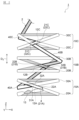
- FIG. 2 is an enlarged side view of a portion of the cable bundle shown in FIG.
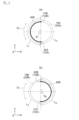
- FIG. 3(a) is a schematic plan view showing the position of a first intermediate portion in the circumferential direction of the cable bundle
- FIG. 3(b) is a schematic plan view showing the position of a second intermediate portion in the circumferential direction of the cable bundle.
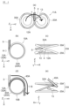
- 4(a) to 4(e) are diagrams showing a method of forming a first unit bundle of cables in the first embodiment of the present invention.
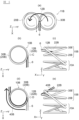
- 5(a) to 5(e) are diagrams showing a method of forming a second unit bundle of cables in the first embodiment of the present invention.
- FIG. 6(a) to 6(e) are diagrams showing a method for forming a third unit bundle of cables in the first embodiment of the present invention.
- FIG. 7 is a perspective view showing the configuration of the eight-shaped loops when the unit bundle in the second embodiment of the present invention is opened.
- FIG. 8 is a side view showing a cable bundle according to the second embodiment of the present invention, and corresponds to FIG.
- FIG. 9 is a development view of a portion of a cable bundle according to the third embodiment of the present invention.
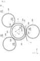
- FIG. 10 is a diagram showing a cable bundle manufacturing apparatus according to the third embodiment of the present invention.
- Fig. 1 is a perspective view showing a cable bundle 1 in a first embodiment of the present invention
- Fig. 2 is an enlarged side view of a portion of the cable bundle 1 shown in Fig. 1.
- Fig. 3(a) is a schematic plan view showing the position of a middle portion 40A of the cable bundle 1 in the circumferential direction D1
- Fig. 3(b) is a schematic plan view showing the position of a middle portion 40B of the cable bundle 1 in the circumferential direction D1 .
- the container 50 is shown in a see-through manner to make it easier to understand the state inside the container 50.
- the white portion of the cable 2 indicates the front side of the cable 2
- the shaded portion of the cable 2 indicates the back side of the cable 2.
- the thick solid line portion of the cable 2 indicates the middle portions 40A, 40B, and 40C of the cable 2
- the thick dashed line portion of the cable 2 indicates the connection portions 12A, 12B, and 12C of the cable 2.
- the cable bundle 1 in this embodiment includes the cable 2 wound in a ring shape (tubular, coil shape) in the winding direction D2 , and is formed by winding a single continuous cable 2 by a winding method described later.
- This cable bundle 1 has a so-called drumless structure that does not have a winding core such as a drum or a reel.
- a specific example of the cable 2 can be an optical fiber cable, but is not limited to this.
- a metal cable for power transmission, communication, or a composite type that combines these may be used as the cable 2.
- the cable 2 in this embodiment does not have any connection point between one end 3 (e.g., the end (E end) of the cable 2 at the end where the winding ends) and the other end 4 (e.g., the end (S end) of the cable 2 at the end where the winding starts) (see FIG. 2), but a single continuous cable 2 may be configured by connecting multiple cables by, for example, fusion splicing, a connector, or the like.
- the cable bundle 1 is transported to the laying site in a state housed in a container 50 as shown in FIG. 1.
- the container 50 has a box-like shape, and an opening 52 is formed on the upper surface thereof.
- the cable 2 is supplied to the laying site by being sequentially unwound from one end 3 to the outside of the container 50 through the opening 52.
- the cable bundle 1 is arranged in the container 50 in a position (i.e., a "vertical position") in which the axial direction D3 of the cable bundle 1 is substantially parallel to the vertical direction (the Z direction in the figure).
- the container 50 is, for example, made of cardboard made of paper, but is not particularly limited thereto.
- the container 50 may be made of plastic cardboard made of a resin material such as polypropylene (PP), or may be made of a metal box.
- PP polypropylene
- this cable bundle 1 comprises a plurality of unit bundles 10A, 10B, 10C, etc. and a plurality of intermediate portions 40A, 40B, 40C, etc.
- Each unit bundle 10A, 10B, 10C, etc. is formed by winding the cable 2 in a figure of eight to form two circular loops and folding the two loops, as will be described in detail later.
- the plurality of unit bundles 10A, 10B, 10C, etc. are stacked vertically (Z direction in the figure).
- Each intermediate portion 40A, 40B, 40C, etc. is a portion of the cable 2 that is interposed between the unit bundles 10A, 10B, 10C, etc. Note that FIG. 2 shows only three unit bundles 10A, 10B, 10C on the other end 4 side of the cable 2, but in reality the cable bundle 1 comprises a large number of unit bundles.
- the unit bundle 10A includes a first ring 20A and a second ring 30A.
- the first and second rings 20A, 30A have substantially the same diameter, but the diameters of the first and second rings 20A, 30A may be different from each other.
- the first ring 20A is formed by winding the cable 2 in a "forward winding”.
- the second ring 30A is formed by winding the cable 2 in a "reverse winding”.
- forward winding refers to winding the cable 2 so that the start point of the loop is located on one side (e.g., the lower side) of the end point in the overlapping direction of the two loops that make up the unit bundle.
- reverse winding refers to winding the cable 2 so that the start point of the loop is located on the other side (e.g., the upper side) of the end point in the overlapping direction of the two loops.
- the cable 2 is wound so that the starting point 21A is located below the end point 22A in the overlapping direction D3 (Z direction in the figure) of the two loops 20A, 30A, so the winding method of this first loop 20A is "forward winding".
- the cable 2 is wound so that the starting point 31A is located above the end point 32A in the overlapping direction D3 (Z direction in the figure) of the two loops 20A, 30A, so the winding method of this second loop 30A is "reverse winding".
- the overlapping direction D3 (Z direction in the figure) of the two loops 20A, 30A corresponds to an example of the "second direction" in this aspect of the present invention.
- this unit bundle 10A is formed by winding in a figure of eight, the two loops 20A, 30A are connected to each other at the connection part 12A.
- the two loops 20A, 30A are connected to each other at the connection part 12A so that when this unit bundle 10A is opened, an eight-shaped loop 11A (see FIG. 4(a) described later) including the first and second loops 20A, 30A is formed.
- the unit bundle 10A is opened (see FIG. 4(a))
- the starting point 21A of the first loop 20A is located below the end point 22A of the first loop 20A
- the starting point 31A of the second loop 30A is also located below the end point 32A of the second loop 30A.
- the first loop 20A is defined by the cable 2 crossing at the start point 21A and the end point 22A of the first loop 20A
- the second loop 30A is defined by the cable 2 crossing at the start point 31A and the end point 32A of the second loop 30A. Therefore, when the first intersection defining the first loop 20A and the second intersection defining the second loop 30A overlap in the circumferential direction D1 of the cable bundle 1 , the connection portion 12A coincides with the first and second intersections in the circumferential direction D1 . On the other hand, when the first and second intersections are offset in the circumferential direction D1 of the cable bundle 1, the connection portion 12A is a portion of the cable 2 between the first and second intersections including the first and second intersections.
- the "figure of eight” in this embodiment includes a complete figure of eight shape in which the connection portion 12A has no length, and also includes a shape in which two loops 20A and 20B are connected by the connection portion 12A that has a length.
- the "figure eight” refers to the Arabic numeral "8.”
- the unit bundle 10B also includes a first loop 20B formed by winding the cable 2 in a forward direction and a second loop 30B formed by winding the cable 2 in a reverse direction.
- first loop 20B the cable 2 is wound so that the starting point 21B is located below the end point 22B in the overlapping direction D3 (Z direction in the figure) of the two loops 20B, 30B, so the winding method of this first loop 20B is "forward winding".
- the second loop 30B the cable 2 is wound so that the starting point 31B is located above the end point 32B in the overlapping direction D3 (Z direction in the figure) of the two loops 20B, 30B, so the winding method of this second loop 30B is "reverse winding".
- the two rings 20B, 30B are stacked in the vertical direction (Z direction in the figure) so that the second ring 30B is located above the first ring 20B.
- the unit bundle 10B is also formed by a figure-of-eight winding
- the two rings 20B, 30B are connected at the connection portion 12B.
- the two rings 20B, 30B are connected to each other at the connection portion 12B so that when the unit bundle 10B is opened, an eight-shaped ring 11B (see FIG. 5(a) described below) including the first and second rings 20B, 30B is formed.
- the starting point 21B of the first ring 20B is located below the end point 22B of the first ring 20B, and the starting point 31B of the second ring 30B is also located below the end point 32B of the second ring 30B.
- the unit bundle 10B is stacked on top of the unit bundle 10A.
- the unit bundles 10A and 10B are connected to each other via an intermediate portion 40A of the cable 2.
- the intermediate portion 40A is a portion of the cable 2 that is interposed between the unit bundles 10A and 10B, and is wound along the circumferential direction D1 of the cable bundle 1.
- This circumferential direction D1 of the cable bundle 1 corresponds to an example of the "first direction" in this aspect of the present invention.
- the length L1 of the intermediate portion 40A may be 1/4 to 3/4 of the circumferential length L2 of the second loop 30A ( L2 x 1/4 ⁇ L1 ⁇ L2 x 3/4), in which case the connection portion 12A of the unit bundle 10A and the connection portion 12B of the unit bundle 10B are offset within a range of 90 degrees to 270 degrees (90° ⁇ ⁇ 1 ⁇ 270°) in the circumferential direction D1 of the cable bundle 1.
- the length L1 of the intermediate portion 40A may be 1/3 to 2/3 of the circumferential length L2 of the second loop 30A ( L2 x 1/3 ⁇ L1 ⁇ L2 x 2/3), in which case the connection portion 12A of the unit bundle 10A and the connection portion 12B of the unit bundle 10B are offset within a range of 120 degrees to 240 degrees in the circumferential direction D1 of the cable bundle 1 (120° ⁇ ⁇ 1 ⁇ 240°).
- the unit bundle 10C also has a first loop 20C formed by winding the cable 2 in a forward direction, and a second loop 30C formed by winding the cable 2 in a reverse direction.
- the two loops 20C, 30C are stacked so that the second loop 30C is located above the first loop 20C in the vertical direction (Z direction in the figure).
- the unit bundle 10C is also formed by a figure-of-eight winding, the two loops 20C, 30C are connected at the connection portion 12C.
- the two loops 20C, 30C are connected to each other at the connection portion 12C so that when the unit bundle 10C is opened, a figure-of-eight-shaped loop 11C (see FIG.
- This unit bundle 10C is stacked on top of the unit bundle 10B. Moreover, these unit bundles 10B and 10C are connected via an intermediate portion 40B of the cable 2. This intermediate portion 40B is a portion of the cable 2 that is interposed between the unit bundles 10B and 10C, and is wound along the circumferential direction D1 of the cable bundle 1.
- the length L3 of the intermediate portion 40B may be 1/4 to 3/4 of the circumferential length L4 of the first loop 20B ( L4 x 1/4 ⁇ L3 ⁇ L4 x 3/4), in which case the connection portion 12B of the unit bundle 10B and the connection portion 12C of the unit bundle 10C are offset within a range of 90 degrees to 270 degrees in the circumferential direction D1 of the cable bundle 1 (90° ⁇ ⁇ 2 ⁇ 270°).
- the length L3 of the intermediate portion 40B may be 1/3 to 2/3 of the circumferential length L4 of the first loop 20B ( L4 x 1/3 ⁇ L3 ⁇ L4 x 2/3), in which case the connection portion 12B of the unit bundle 10B and the connection portion 12C of the unit bundle 10C are offset within a range of 120 degrees to 240 degrees in the circumferential direction D1 of the cable bundle 1 ( 120 ° ⁇ ⁇ 2 ⁇ 240°).
- a twist 13 is imparted to the unit bundle 10A near the end 4 on the winding start side.
- This twist 13 is imparted to the cable 2 by twisting the cable 2 one turn in a direction opposite to the twist caused by the intermediate portions 40A, 40B when the cable 2 is unwound from the cable bundle 1.
- this twist 13 is imparted to the cable 2 by twisting the cable 2 one turn in a direction opposite to the winding direction D2 (see FIG. 1) of the cable bundle 1 when the cable bundle 1 is viewed from the pull-out side (end portion 3 side) of the cable 2.
- This one-turn twist 13 of the unit bundle 10 can offset the twist caused by the two intermediate portions 40A, 40B corresponding to one revolution of the cable bundle 1 when the cable 2 is unwound from the cable bundle 1.
- the unit bundles above the unit bundle 10C shown in Fig. 2 among the multiple unit bundles are configured by alternating the above-mentioned unit bundles 10B and 10C (hereinafter simply referred to as "unit bundle 10B'" and “unit bundle 10C'”). These unit bundles 10B', 10C' are connected via the above-mentioned middle portion 40B, and the connection portions 12B, 12C of the unit bundles 10B', 10C' adjacent to each other in the overlapping direction D3 of the unit bundles (Z direction in the figure) are shifted in the circumferential direction D1 of the cable bundle 1.
- this intermediate portion 40C has a length that is half the circumferential length of the first loop 20C of the lower unit bundle 10C to which the intermediate portion 40C is connected. Therefore, the connection portions 12C and 12B of the unit bundles 10C and 10B' (or unit bundles 10C' and 10B') adjacent to each other in the overlapping direction D3 of the unit bundles (Z direction in the figure) are also shifted in the circumferential direction D1 of the cable bundle 1.
- a one-turn twist 13 is imparted to the two unit bundles 10B' and 10C'.
- the position where the twist 13 is applied in the cable bundle 1 is not limited to the vicinity of the end of the unit bundle.
- the twist 13 may be applied at any position in the unit bundle, or the twist 13 may be applied to the middle part connecting the unit bundles.
- the total number of rotations R of all the twists 13 applied to the entire cable bundle 1 is preferably equal to or less than the value obtained by dividing the total length L t of all the middle parts 40A, 40B, ... of the cable bundle 1 by the average circumference L 0 of the cable bundle 1 (R ⁇ L t /L 0 ), and it is more preferable that the number of rotations R is equal to the value obtained by dividing the total length L t of the middle parts 40A, 40B, ...
- the average circumference L 0 of the cable bundle 1 is a value obtained by dividing the total length of the cable 2 by the number of turns of the cable 2.
- Figures 4(a) to 6(e) are diagrams showing a method for forming unit bundle 10A of cable bundle 1 in the first embodiment of the present invention
- Figures 5(a) to 5(e) are diagrams showing a method for forming unit bundle 10B of cable bundle 1 in the first embodiment of the present invention
- Figures 6(a) to 6(e) are diagrams showing a method for forming unit bundle 10C of cable bundle 1 in the first embodiment of the present invention.
- Fig. 4(c) is a view of unit bundle 10A from direction A in Fig. 4(b), and Fig. 4(e) is a view of unit bundle 10A from direction B in Fig. 4(d).
- Fig. 5(c) is a view of unit bundle 10B from direction C in Fig. 5(b)
- Fig. 5(e) is a view of unit bundle 10B from direction D in Fig. 5(d).
- Fig. 6(c) is a view of unit bundle 10C from direction E in Fig. 6(b)
- Fig. 6(e) is a view of unit bundle 10C from direction F in Fig. 6(d).
- the cable 2 is arranged in an 8-shape to form a third loop 11A in an 8-shape.
- This third loop 11A has first and second loops 20A, 30A connected by a connection portion 12A.
- the cable 2 is wound around the first loop 20A so that the starting point 21A is located below the end point 22A, making the winding method for the first loop 20A "forward winding".
- the cable 2 is also wound around the second loop 30A so that the starting point 31A is located below the end point 32A. If the second loop 30A is then reversed, the winding method for the second loop 30A becomes "reverse winding".
- a twist 13 is formed in the first loop 20A near the end 4 of the cables 2.
- This twist 13 is imparted to the cables 2 by twisting the cables 2 one turn in a direction opposite to the winding direction D2 (see FIG. 1 ) of the cable bundle 1 when the cable bundle 1 is viewed from the pull-out side (end 3 side) of the cables 2.
- the winding direction D2 of the cable bundle 1 is clockwise, so that a twist 13 is imparted to the cables 2 such that the cable 2 is counterclockwise.
- the third loop 11A in the shape of a figure 8 is folded at the connection portion 12A, and the second loop 30A is placed on top of the first loop 20A to form the unit bundle 10A.
- a portion 5 of the cable 2 (a portion 5 of the cable 2 on the end portion 3 side of the end point 32A of the second loop 30A) is wound 180 degrees along the circumferential direction D1 of the cable bundle 1.
- This portion 5 of the cable 2 corresponds to the intermediate portion 40A between the unit bundles 10A and 10B.
- the portion of the cable 2 following the portion 5 is arranged in an 8-shape to form a third loop 11B in an 8-shape.
- This third loop 11B has first and second loops 20B, 30B connected by a connection portion 12B.
- the cable 2 is wound around the first loop 20B so that the starting point 21B is located below the end point 22B, and the winding method of the first loop 20B is "forward winding".
- the cable 2 is also wound around the second loop 30B so that the starting point 31B is located below the end point 32B. If the second loop 30B is then reversed, the winding method of the second loop 30B becomes "reverse winding". Note that no twist 13 is imparted to this third loop 11B.
- the first wheel 20B and the second wheel 30B are opposite in positional relationship compared to the first and second wheels 20A, 30A in the first tier third wheel 11A described above. That is, in the first tier third wheel 11A shown in FIG. 4(a), the first wheel 20A is located on the right side of the second wheel 30A, whereas in the second tier third wheel 11B shown in FIG. 5(a), the first wheel 20B is located on the left side of the second wheel 30B.
- the third loop 11B in the figure-8 shape is folded at the connection portion 12B, and the second loop 30B is placed on top of the first loop 20B to form the unit bundle 10B.
- a portion 6 of the cable 2 (a portion 6 of the cable 2 on the end portion 3 side of the end point 22B of the first loop 20B) is wound 180 degrees in the circumferential direction D1 of the cable bundle 1. This portion 6 of the cable 2 corresponds to the intermediate portion 40B between the unit bundles 10B and 10C.
- the portion of the cable 2 following the portion 6 is arranged in an 8-shape to form a third loop 11C in an 8-shape.
- This third loop 11C includes first and second loops 20C, 30C connected by a connection portion 12C.
- the cable 2 is wound around the first loop 20C so that the starting point 21C is located below the end point 22C, making the winding method of the first loop 20C "forward winding".
- the cable 2 is also wound around the second loop 30C so that the starting point 31C is located below the end point 32C. If the second loop 30C is then reversed, the winding method of the second loop 30C becomes "reverse winding". Note that no twist 13 is imparted to this third loop 11C either.
- the first wheel 20C and the second wheel 30C are reversed in positional relationship compared to the first and second wheels 20B, 30B in the second tier third wheel 11B described above. That is, in the second tier third wheel 11B shown in FIG. 5(a), the first wheel 20B is located on the left side of the second wheel 30B, whereas in the third tier third wheel 11C shown in FIG. 6(a), the first wheel 20C is located on the right side of the second wheel 30C.
- the third loop 11C in the figure-8 shape is folded at the connection portion 12C, and the second loop 30C is placed on top of the first loop 20C to form the unit bundle 10C.
- portion 7 of cable 2 (portion 7 of cable 2 on the end portion 3 side of end point 22C of first loop 20C) is wound 180 degrees in the circumferential direction D1 of cable bundle 1. Note that portion 7 of cable 2 corresponds to intermediate portion 40C between unit bundle 10C and the next unit bundle (the above-mentioned unit bundle 10B').
- the cable bundle 1 is formed by alternately forming unit bundles and intermediate portions.
- the unit bundles above unit bundle 10C shown in FIG. 2 among the multiple unit bundles are constructed by alternating unit bundles 10B' and unit bundles 10C', and these unit bundles 10B' and 10C' are connected via intermediate portion 40B of cable 2 described above. Also, unit bundle 10C' and the unit bundle 10B' above it are connected via intermediate portion 40C described above.
- the formation and stacking of unit bundles is repeated from the bottom up, but the method is not limited to this.
- all the unit bundles may be stacked.
- the third rings may be folded to form all unit bundles, and then all the unit bundles may be stacked.
- unit bundles may be formed without going through the figure-8 opening state.
- connection parts (e.g., 12A, 12B) of unit bundles (e.g., unit bundles 10A, 10B) adjacent to each other in the overlapping direction D3 (Z direction in the figure) of the unit bundles 10A, 10B, 10C, ... are shifted in the circumferential direction D1 of the cable bundle 1.
- the upper unit bundle (e.g., unit bundle 10B) functions as a weight relative to the rings of the lower unit bundle (e.g., rings 20A, 30A of unit bundle 10A), thereby suppressing the lifting up of the rings that are subsequently paid out (e.g., rings 20A, 30A of unit bundle 10A), and thus preventing the cable 2 from becoming entangled.
- FIG. 7 is a perspective view showing the configuration of the figure-8 ring 11 when the unit bundle 10 in the second embodiment of the present invention is opened.
- the starting point 21 of the first loop 20 is located below the end point 22 of the first loop 20.
- the end point 32 of the second loop 30 is located below the starting point 31 of the second loop 30 and the starting point 21 of the first loop 20, and a portion 8 of the cable 2 (a portion 8 of the cable 2 that is closer to the end 4 than the starting point 21 of the first loop 20) passes through the second loop 30.
- a cable bundle 1B shown in FIG. 8 is formed.
- the cable 2 is wound around the first loop 20B so that the starting point 21B is located above the end point 22B in the overlapping direction D 3 (Z direction in the figure) of the two loops 20B and 30B, so the winding method of the first loop 20A is "reverse winding".
- the cable 2 is also wound around the second loop 30B so that the starting point 31B is located above the end point 32B in the overlapping direction D 3 (Z direction in the figure) of the two loops 20B and 30B, so the winding method of the second loop 30B is "reverse winding".
- the winding methods of the first and second loops 20B and 30B are both "reverse winding".
- the first and second loops 20C and 30C are both wound in the "reverse winding" manner.
- connection portion of the unit bundle may have a length.
- a cable bundle 1C according to a third embodiment of the present invention will be described with reference to FIG. 9.
- FIG. 9 is an exploded view of a portion of cable bundle 1C according to the third embodiment of the present invention.
- the cable bundle 1C of this embodiment includes a plurality of unit bundles 10A, 10B, ... and a plurality of intermediate portions 40A, 40B, ....
- the cable 2 is twisted to form individual loops in sequence, and the loops are stacked in sequence to form the cable bundle 1C.
- FIG. 9 only illustrates two unit bundles 10A, 10B at the end 4 of the cable 2, but in reality the cable bundle 1C includes many unit bundles.
- FIG. 9 is an exploded view of the cable bundle 1C, it shows the unit bundles 10A, 10B in an open state, but in reality the multiple unit bundles 10A, 10B, ... are stacked vertically (Z direction in the figure).
- the unit bundle 10A includes a first loop 20A and a second loop 30A.
- the first loop 20A is formed by winding the cable 2 so that the starting point 21A is located above the end point 22A, and the winding method of the first loop 20A is "reverse winding".
- the second loop 30A is formed by winding the cable 2 so that the starting point 31A is located below the end point 32A, and the winding method of the second loop 30B is "forward winding".
- FIG. 9 shows the cable bundle 1C in an open state, and therefore the starting point 31A of the second loop 30A is located above the end point 32A.
- the two loops 20A, 30A are stacked so that the second loop 30A is located above the first loop 20A in the vertical direction (Z direction in the figure).
- the two loops 20A, 30A are connected via a connection part 12A so that when the unit bundle 10A is opened, an eight-shaped loop 11A is formed with the first and second loops 20A, 30A.
- connection portion 12A of the unit bundle 10A is a portion of the cable 2 between the intersections 23A and 33A of the first and second loops 20A and 30A, so that the connection portion 12A of this embodiment has a predetermined length.
- This connection portion 12A is wound along the circumferential direction D1 of the cable bundle 1C.
- the length of this connection portion 12A has a length corresponding to the central angle ⁇ 3 in the circumferential direction D1 of the cable bundle 1C.
- the central angle defining the length of this connection portion is preferably 120° or less.
- the unit bundle 10B also has a first loop 20B and a second loop 30B.
- the first loop 20B is formed by winding the cable 2 so that the starting point 21B is located above the end point 22B, so the winding method of this second loop 30B is "reverse winding”.
- the second loop 30B is also formed by winding the cable 2 so that the starting point 31B is located above the end point 32B, so the winding method of this second loop 30B is also "reverse winding”.
- Figure 9 shows the cable bundle 1C in an open state, so the starting point 21B of the first loop 20B is located below the end point 22B, and the starting point 31B of the second loop 30B is also located below the end point 32B.
- the two rings 20B, 30B are stacked so that the second ring 30B is positioned above the first ring 20B in the vertical direction (Z direction in the figure).
- the two rings 20B, 30B are connected via a connection part 12B so that when the unit bundle 10B is opened, an eight-shaped ring 11B including the first and second rings 20B, 30B is formed.
- the second ring 30B may be wound in a "normal winding" manner.
- connection portion 12B of the unit bundle 10B is a portion of the cable 2 between the intersections 23B and 33B of the first and second loops 20B and 30B, so that the connection portion 12B of this embodiment has a predetermined length.
- This connection portion 12B is wound along the circumferential direction D1 of the cable bundle 1C.
- connection portion 12B has a length corresponding to the central angle ⁇ 4 in the circumferential direction D1 of the cable bundle 1C.
- the unit bundle 10B is stacked on the unit bundle 10A. At this time, the starting point 31B and the end point 32B of the second loop 30B of the unit bundle 10B are located above the starting point 21A and the end point 22A of the first loop 20A of the unit bundle 10A.
- the unit bundles 10A and 10B are connected via the middle part 40A of the cable 2.
- the middle part 40A is a part of the cable 2 between the end point 32B of the second loop 30A of the unit bundle 10A and the starting point 21B of the first loop 20B of the unit bundle 10B, and is wound along the circumferential direction D1 of the cable bundle 1C.
- the length of the middle part 40A has a length corresponding to the central angle ⁇ 5 in the circumferential direction D1 of the cable bundle 1C.
- connection parts 12A, 12B and the intermediate part 40A of the unit bundles 10A, 10B each have a length corresponding to 120° in the circumferential direction D1 of the cable bundle 1C, so that the sum of these forms one loop along the circumferential direction D1 of the cable bundle 1C.
- the winding of the loop formed by the connection parts 12A, 12B and the intermediate part 40A and the winding of the second loop 30B of the unit bundle 10A are "forward winding"
- the winding of the first loop 20A of the unit bundle 10A and the winding of the first loop 20B of the unit bundle 10B are "reverse winding"
- the number of "forward winding" loops and the number of "reverse winding” loops are the same. Therefore, since the twist is zero in these four loops, it is not necessary to form the twist 13 described in the first embodiment in the cable bundle 1C.
- the total number of the first and second loops connected via the connection parts and the intermediate part is not particularly limited to the above, as long as it is an odd number.
- the winding method of each loop is not particularly limited to the above, as long as the number of "forward winding" loops and the number of "reverse winding" loops are the same.
- the lengths of the connection parts and the intermediate part that form one loop along the circumferential direction D1 of the cable bundle 1C do not have to be equal.
- FIG. 10 is a diagram showing a manufacturing device 60 for a cable bundle 1C according to a third embodiment of the present invention.
- the manufacturing device 60 in this embodiment includes a holding device 61, a twisting device 62, a fixing device 63, a rotating device 64, and a control device 65.
- the holding device 61 holds a drum 611 around which the cable 2 is wound.
- the drum 611 is held by the holding device 61 so as to be rotatable about a central axis RA -1 of the drum 611.
- the drum 611 passively rotates as the cable 2 is pulled out by the caterpillar 621 of the twisting device 62, but the holding device 61 may be provided with a drive device that drives the drum 611 to rotate about the rotation axis RA -1 of the drum 611.
- the drive device works in conjunction with the caterpillar 621 of the twisting device 62 to actively feed out the cable 2 from the drum 611.
- the holding device 61 may also include a rotation device 612 that rotates the drum 611 about a rotation axis RA2 that is substantially parallel to the payout direction D4 of the cable 2 from the drum 611. This makes it possible to easily remove the twist from the cable 2 when a twist occurs in the portion of the cable 2 between the drum 611 and the twisting device 62.
- the rotation axis RA2 is also an axis that is substantially perpendicular to the rotation axis RA1 of the drum 611.
- the rotation axis RA2 corresponds to an example of a "second axis" in this aspect of the present invention.
- the twisting device 62 includes a pair of caterpillars 621, a frame 625, and a rotating device 626.
- Each caterpillar 621 includes a pair of pulleys 622, an endless belt 623 looped around the pulley 622, and a driving device 624 for rotating the pulley 622.
- the pair of caterpillars 621 are arranged so that the belts 623 are in close contact with each other, and the cable 2 supplied from the drum 611 can be sandwiched between the belts 623.
- the driving device 624 includes a motor and a gear box for rotating the pulley 622, and by driving the caterpillars 621, it is possible to pull out the cable 2 from the drum 611 and push out the cable 2 from the twisting device 62.
- This pair of caterpillars 621 corresponds to an example of a "sending device" in this aspect of the present invention.
- the pair of caterpillars 621 are housed in a frame 625.
- the rotating device 626 includes a motor, a gear box, and the like for rotating the frame 625.
- the rotating device 626 is capable of twisting the cable 2, which is sandwiched between the pair of caterpillars 621, by rotating the frame 625 about the axial direction of the cable 2.
- the rotating device 626 is capable of rotating the frame 625 360° in one rotation direction D5 , and is also capable of rotating the frame 625 360° in the other rotation direction D6 .
- the one rotation direction D5 corresponds to an example of a "third direction" in this aspect of the present invention
- the other rotation direction D6 corresponds to an example of a "fourth direction" in this aspect of the present invention.
- the configuration of the twisting device 62 is not particularly limited to the above, so long as it has a mechanism for feeding out the cable 2 and a function for twisting the cable 2.
- the twisting device 62 may have a gripping part that grips the cable and a moving part that moves the gripping part along the axial direction of the cable 2, and the gripping part may have a plurality of rollers that can twist the cable.
- the function of feeding out the cable 2 and the function of twisting the cable 2 may be achieved by devices that are independent of each other.
- the fixing device 63 is a device that fixes the cable 2 sent out from the twisting device 62. Although not limited to this, a specific example of this fixing device 63 is a clamp that clamps and fixes the fixed position FP of the cable 2 using an air cylinder or the like. This fixing device 63 fixes the movement of the cable 2 along the axial direction at the fixed position FP on the cable 2.
- This fixed position FP is a position on the cable 2 that is a predetermined distance away from the twisting device 62. This predetermined distance is a distance that allows one loop 15 of the cable 2 (e.g., the first loop 20A) to be formed between the fixed position FP and the twisting device 62.
- the caterpillar 621 of the twisting device 62 sends out the cable 2 toward the fixed position FP, and when the rotating device 626 of the twisting device 62 rotates the cable 2 in one rotation direction D5 , a "reverse winding" loop is formed.
- a "forward winding" loop is formed.
- the rotating device 64 includes a mounting table 641 and a driving device 642.
- the rings 15 formed by the twisting device 62 are placed on the mounting table 641 and stacked.
- the mounting table 641 includes a mounting surface on which the rings 15 of the cable 2 are placed.
- the driving device 642 includes a motor, a gear box, and the like for rotating the mounting surface of the mounting table 641.
- the driving device is capable of rotating the mounting surface of the mounting table 641 around a rotation axis RA 3 that is substantially parallel to the normal direction of the mounting table 641.
- the rotation axis RA 3 corresponds to an example of the "first axis" in the aspect of the present invention.
- the driving device 642 rotates the mounting surface of the mounting table 641 only counterclockwise, but the driving device 642 may rotate the mounting surface of the mounting table 641 in both clockwise and counterclockwise directions.
- the control device 65 is, for example, configured with a computer.
- This computer is an electronic calculator equipped with a CPU (processor), a main memory device (RAM, etc.), a secondary memory device (hard disk, SSD, etc.), and an interface, etc., although not specifically shown.
- This control device 65 is controllably connected to the drive device 624 and rotation device 626 of the twisting device 62 described above, the fixing device 63, and the drive device 642 of the rotation device 64. These controls are functionally realized, for example, by the control device 65 executing a program. Note that this control device 65 may be configured with a circuit board instead of a computer.
- the control device 65 sends a control signal to the fixing device 63, and the fixing device 63 clamps the fixing position FP on the cable 2.
- the fixing device 63 fixes the movement of the cable 2 along the axial direction at the fixing position FP on the cable 2.
- control device 65 sends a control signal to the drive device 624 of the twisting device 62, and the caterpillar 621 sends out a predetermined amount of the cable 2 from the twisting device 62.
- This predetermined amount is the length equivalent to one loop 15 of the cable 2, and is a value input in advance to the control device 65.
- the control device 65 transmits a control signal to the rotation device 626 of the twisting device 62, and the rotation device 626 rotates the frame 625 360° in one rotation direction D5 to twist the cable 2, thereby forming a "reverse-wound" first loop 20A.
- This first loop 20A is placed on the placement table 641 of the rotation device 64.
- the twisting device 62 may twist the cable 2 while feeding out a predetermined amount of the cable 2.
- the control device 65 transmits a control signal to the fixing device 63, and the fixing device 63 releases the cable 2 to release the fixing of the cable 2.
- the control device 65 transmits a control signal to the driving device 642 of the rotating device 64 and the driving device 624 of the twisting device 62.
- the driving device 642 rotates the mounting surface of the mounting table 641 by a central angle ⁇ 3 , and at the same time, the caterpillar 621 feeds out a predetermined amount of the cable 2 from the twisting device 62.
- This predetermined amount is a length corresponding to the central angle ⁇ 3 in the circumferential direction D 1 of the cable bundle 1C, and is a value input in advance to the control device 65.
- the connection portion 12A of the unit bundle 10A in the cable bundle 1C is formed.
- the second loop 30A of the unit bundle 10A is formed in the same manner as the formation of the first loop 20A described above.
- the rotation device 626 rotates the frame 625 360° in the other rotation direction D6 to twist the cable 2, thereby forming the second loop 30A with a "forward winding".
- This second loop 30A is placed on the placement table 641 of the rotation device 64, and the unit bundle 10A is formed.
- the twisting device 62 may twist the cable 2 while feeding out a predetermined amount of the cable 2.
- the control device 65 transmits a control signal to the fixing device 63, and the fixing device 63 releases the cable 2 to release the fixing of the cable 2.
- the control device 65 transmits a control signal to the driving device 642 of the rotating device 64 and the driving device 624 of the twisting device 62.
- the driving device 642 rotates the mounting surface of the mounting table 641 by a central angle ⁇ 5 , and at the same time, the caterpillar 621 feeds out a predetermined amount of the cable 2 from the twisting device 62.
- This predetermined amount is a length corresponding to the central angle ⁇ 5 in the circumferential direction D 1 of the cable bundle 1C, and is a value input in advance to the control device 65.
- the intermediate portion 40A between the unit bundles 10A and 10B is formed in the cable bundle 1C.
- unit bundles and intermediate portions are alternately formed to form cable bundle 1C. If a twist occurs in cable 2 between drum 611 and twisting device 62, the twist can be removed by rotating drum 611 using rotation device 612 described above.
- the driving device 642 of the rotating device 64 rotates the mounting surface of the mounting table 641 on which the loop 15 of the cable 2 is placed, so that a cable bundle 1C having connection portions 12A, 12B that are offset in the circumferential direction D1 can be manufactured.
- the manufacturing apparatus 60 may also include a measuring device 66 that measures the length of the cable 2 sent out by the twisting device 62.
- the control device 65 may control the drive device 624 of the twisting device 62 based on the measurement results of the measuring device 66 so that the caterpillar 621 sends out a predetermined amount of the cable 2 from the twisting device 62.
- a specific example of such a measuring device 66 is an encoder.
- the length of the cable 2 sent out from the twisting device 62 may be measured by the measuring device 66 to perform quality control of the cable bundle 1.
- the cable bundle 1 shown in FIG. 1 may also be manufactured using the manufacturing apparatus 60 described above.
- the manufacturing apparatus 60 includes an additional fixing device 67 in addition to the fixing device 63 described above.
- This additional fixing device 67 has a similar configuration to the fixing device 63 described above.
- the fixing device 63 is used to form the first loop
- the additional fixing device 67 is used to form the second loop.
- the cable bundle 1 has a drumless structure that does not have a winding core, but is not particularly limited to this.
- the cable bundle 1 may have a winding core, or the cable bundle 1 may be formed around a payout guide pin.
- multiple unit bundles 10A, 10B, 10C, ... are stacked in a direction perpendicular to the radial direction (unit bundle stacking direction D3 (Z direction in the figure)), but this is not particularly limited.
- unit bundle stacking direction D3 Z direction in the figure
- by appropriately changing the size of the diameter of the rings constituting each unit bundle multiple unit bundles having different diameters arranged on the same plane may be stacked in the stacking direction D3 .
- another unit bundle having a diameter larger than the diameter of the unit bundle may be stacked in the stacking direction D3 on the outside of the multiple unit bundles stacked in the stacking direction D3 .
- the connection parts of the unit bundles may be shifted in the circumferential direction D1 of the cable bundle 1.
- the first intersection point and the second intersection point may be shifted in the circumferential direction D1 of the cable bundle 1.
- Twisting device 621 Caterpillar 622: Pulley 623: Belt 624: Driving device 625: Frame 626: Rotating device 63: Fixing device 64: Rotating device 641: Placement table 642: Driving device 65: Control device 66: Measuring device 67: Fixing device
Landscapes
- Engineering & Computer Science (AREA)
- Textile Engineering (AREA)
- Storage Of Web-Like Or Filamentary Materials (AREA)
- Insulated Conductors (AREA)
- Details Of Indoor Wiring (AREA)
Priority Applications (4)
| Application Number | Priority Date | Filing Date | Title |
|---|---|---|---|
| US19/131,147 US20260008647A1 (en) | 2022-11-24 | 2023-11-20 | Cable bundle, cable bundle manufacturing method, and cable bundle manufacturing apparatus |
| EP23869322.0A EP4397611A4 (en) | 2022-11-24 | 2023-11-20 | WIRE HARNESS, WIRE HARNESS MANUFACTURING METHOD, AND WIRE HARNESS MANUFACTURING DEVICE |
| JP2024519925A JP7656149B2 (ja) | 2022-11-24 | 2023-11-20 | ケーブル束、ケーブル束の製造方法、及び、ケーブル束の製造装置 |
| CN202380073046.3A CN120051429A (zh) | 2022-11-24 | 2023-11-20 | 线缆束、线缆束的制造方法以及线缆束的制造装置 |
Applications Claiming Priority (2)
| Application Number | Priority Date | Filing Date | Title |
|---|---|---|---|
| JP2022-187748 | 2022-11-24 | ||
| JP2022187748 | 2022-11-24 |
Publications (1)
| Publication Number | Publication Date |
|---|---|
| WO2024111561A1 true WO2024111561A1 (ja) | 2024-05-30 |
Family
ID=91195597
Family Applications (1)
| Application Number | Title | Priority Date | Filing Date |
|---|---|---|---|
| PCT/JP2023/041683 Ceased WO2024111561A1 (ja) | 2022-11-24 | 2023-11-20 | ケーブル束、ケーブル束の製造方法、及び、ケーブル束の製造装置 |
Country Status (6)
| Country | Link |
|---|---|
| US (1) | US20260008647A1 (https=) |
| EP (1) | EP4397611A4 (https=) |
| JP (1) | JP7656149B2 (https=) |
| CN (1) | CN120051429A (https=) |
| TW (1) | TWI889024B (https=) |
| WO (1) | WO2024111561A1 (https=) |
Citations (3)
| Publication number | Priority date | Publication date | Assignee | Title |
|---|---|---|---|---|
| JPS52142926U (https=) * | 1977-04-15 | 1977-10-29 | ||
| JP2001310868A (ja) * | 2000-04-28 | 2001-11-06 | Yazaki Corp | 平形ケーブル束及びケーブル束製造装置 |
| JP2022187748A (ja) | 2021-06-08 | 2022-12-20 | 日本エイアンドエル株式会社 | 熱可塑性樹脂組成物および成形品 |
Family Cites Families (11)
| Publication number | Priority date | Publication date | Assignee | Title |
|---|---|---|---|---|
| US5129514A (en) * | 1991-08-12 | 1992-07-14 | The Ensign-Bickford Company | Flexible cord winding and packaging configuration and method for making such package |
| US6145781A (en) * | 1997-07-10 | 2000-11-14 | Sumitomo Wiring Systems, Ltd. | Cable storage case permitting easy removal of cable stored therein |
| JP2001195933A (ja) * | 2000-01-11 | 2001-07-19 | Hitachi Cable Ltd | 撚伝達装置 |
| US7330627B2 (en) * | 2006-04-07 | 2008-02-12 | Tyco Electronics Corporation | Coiled cable products and methods of forming the same |
| US20080296426A1 (en) * | 2007-06-01 | 2008-12-04 | Cairns James L | Apparatus and method for managing flexible lines |
| JP2013184795A (ja) * | 2012-03-08 | 2013-09-19 | Fujikura Ltd | 光ケーブル巻回体、光ケーブル梱包体、光ケーブルの巻回方法及び光ケーブルの梱包方法 |
| US20140061356A1 (en) * | 2012-08-31 | 2014-03-06 | Adc Telecommunications, Inc. | Cable packing systems and methods |
| JP6484600B2 (ja) * | 2016-10-12 | 2019-03-13 | 矢崎総業株式会社 | ツイスト線製造装置 |
| CN107472990A (zh) * | 2017-09-30 | 2017-12-15 | 中国船舶重工集团公司第七0七研究所 | 一种长电缆防扭力累积的8字绕线装置及方法 |
| WO2020011334A1 (en) * | 2018-07-09 | 2020-01-16 | Prysmian S.P.A | Optical fiber installation kit and corresponding methods for using and manufacturing the same |
| US12269708B2 (en) * | 2020-12-24 | 2025-04-08 | Fujikura Ltd. | Housing unit and wound body |
-
2023
- 2023-11-20 US US19/131,147 patent/US20260008647A1/en active Pending
- 2023-11-20 EP EP23869322.0A patent/EP4397611A4/en active Pending
- 2023-11-20 CN CN202380073046.3A patent/CN120051429A/zh active Pending
- 2023-11-20 JP JP2024519925A patent/JP7656149B2/ja active Active
- 2023-11-20 WO PCT/JP2023/041683 patent/WO2024111561A1/ja not_active Ceased
- 2023-11-23 TW TW112145328A patent/TWI889024B/zh active
Patent Citations (3)
| Publication number | Priority date | Publication date | Assignee | Title |
|---|---|---|---|---|
| JPS52142926U (https=) * | 1977-04-15 | 1977-10-29 | ||
| JP2001310868A (ja) * | 2000-04-28 | 2001-11-06 | Yazaki Corp | 平形ケーブル束及びケーブル束製造装置 |
| JP2022187748A (ja) | 2021-06-08 | 2022-12-20 | 日本エイアンドエル株式会社 | 熱可塑性樹脂組成物および成形品 |
Non-Patent Citations (1)
| Title |
|---|
| See also references of EP4397611A4 |
Also Published As
| Publication number | Publication date |
|---|---|
| TW202431740A (zh) | 2024-08-01 |
| EP4397611A1 (en) | 2024-07-10 |
| JPWO2024111561A1 (https=) | 2024-05-30 |
| EP4397611A4 (en) | 2025-03-19 |
| JP7656149B2 (ja) | 2025-04-02 |
| CN120051429A (zh) | 2025-05-27 |
| TWI889024B (zh) | 2025-07-01 |
| US20260008647A1 (en) | 2026-01-08 |
Similar Documents
| Publication | Publication Date | Title |
|---|---|---|
| JP7307859B2 (ja) | 光ファイバケーブル | |
| CN107076954B (zh) | 光缆、光缆的制造方法以及制造装置 | |
| US7891070B2 (en) | Method for handling elongate strength members | |
| CN103796939B (zh) | 纤维束供给装置 | |
| JP6046311B2 (ja) | テープ心線の製造方法 | |
| WO2022004362A1 (ja) | 光ケーブル及び光ケーブルの製造方法 | |
| JP7656149B2 (ja) | ケーブル束、ケーブル束の製造方法、及び、ケーブル束の製造装置 | |
| JPH02144507A (ja) | 光ケーブルを製造する方法並びに装置 | |
| CN111149033A (zh) | 光纤线缆 | |
| JP5568071B2 (ja) | 光ファイバケーブル | |
| CA3272443A1 (en) | Cable bundle, method of manufacturing cable bundle, and cable bundle manufacturing apparatus | |
| JP7426873B2 (ja) | 光ファイバケーブル | |
| WO2021101654A1 (en) | Optical fiber cable with drop cables having preattached optical connectors and method to strand the same | |
| WO2023127419A1 (ja) | 光ファイバ集合体、光ファイバケーブル、および光ファイバ集合体の製造方法 | |
| CN1246718C (zh) | 组装光缆的设备和方法 | |
| JPWO2024111561A5 (https=) | ||
| TWI818525B (zh) | 光纖纜線及光纖纜線製造方法 | |
| KR102891688B1 (ko) | 콘트롤케이블 아우터 케이싱 제조장치 | |
| JP2023114328A (ja) | 光ファイバケーブル | |
| WO2023127420A1 (ja) | 光ファイバ集合体、光ファイバケーブル、および光ファイバ集合体の製造方法 | |
| JP7730381B2 (ja) | スロットレス型の光ケーブル | |
| JP2009204801A (ja) | 光ファイバケーブルおよび光ファイバケーブルの製造方法 | |
| WO2019199938A1 (en) | Cable with improved wound configuration and method and apparatus for winding cable | |
| TW202600417A (zh) | 捆束裝置以及捆束系統 | |
| WO2023127418A1 (ja) | 光ファイバ集合体、光ファイバケーブル、および光ファイバ集合体の製造方法 |
Legal Events
| Date | Code | Title | Description |
|---|---|---|---|
| WWE | Wipo information: entry into national phase |
Ref document number: 2024519925 Country of ref document: JP |
|
| ENP | Entry into the national phase |
Ref document number: 2023869322 Country of ref document: EP Effective date: 20240405 |
|
| 121 | Ep: the epo has been informed by wipo that ep was designated in this application |
Ref document number: 23869322 Country of ref document: EP Kind code of ref document: A1 |
|
| WWE | Wipo information: entry into national phase |
Ref document number: P2025-00735 Country of ref document: AE |
|
| WWE | Wipo information: entry into national phase |
Ref document number: 202380073046.3 Country of ref document: CN |
|
| WWE | Wipo information: entry into national phase |
Ref document number: 202517038675 Country of ref document: IN |
|
| WWP | Wipo information: published in national office |
Ref document number: 202380073046.3 Country of ref document: CN |
|
| WWP | Wipo information: published in national office |
Ref document number: 202517038675 Country of ref document: IN |
|
| NENP | Non-entry into the national phase |
Ref country code: DE |