WO2024111561A1 - Cable bundle, cable bundle manufacturing method, and cable bundle manufacturing device - Google Patents
Cable bundle, cable bundle manufacturing method, and cable bundle manufacturing device Download PDFInfo
- Publication number
- WO2024111561A1 WO2024111561A1 PCT/JP2023/041683 JP2023041683W WO2024111561A1 WO 2024111561 A1 WO2024111561 A1 WO 2024111561A1 JP 2023041683 W JP2023041683 W JP 2023041683W WO 2024111561 A1 WO2024111561 A1 WO 2024111561A1
- Authority
- WO
- WIPO (PCT)
- Prior art keywords
- cable
- bundle
- unit
- loop
- cable bundle
- Prior art date
Links
- 238000004519 manufacturing process Methods 0.000 title claims description 40
- 238000004804 winding Methods 0.000 claims description 100
- 238000000034 method Methods 0.000 claims description 40
- 238000007599 discharging Methods 0.000 claims 1
- 238000010586 diagram Methods 0.000 description 8
- 239000004743 Polypropylene Substances 0.000 description 2
- 230000015572 biosynthetic process Effects 0.000 description 2
- 238000007667 floating Methods 0.000 description 2
- 239000002184 metal Substances 0.000 description 2
- 229920001155 polypropylene Polymers 0.000 description 2
- 238000005452 bending Methods 0.000 description 1
- 230000005540 biological transmission Effects 0.000 description 1
- 238000004891 communication Methods 0.000 description 1
- 239000002131 composite material Substances 0.000 description 1
- 238000013461 design Methods 0.000 description 1
- 238000011161 development Methods 0.000 description 1
- 238000007526 fusion splicing Methods 0.000 description 1
- 238000010348 incorporation Methods 0.000 description 1
- 239000000463 material Substances 0.000 description 1
- 238000005259 measurement Methods 0.000 description 1
- 238000012986 modification Methods 0.000 description 1
- 230000004048 modification Effects 0.000 description 1
- 239000013307 optical fiber Substances 0.000 description 1
- 239000000123 paper Substances 0.000 description 1
- 239000004033 plastic Substances 0.000 description 1
- -1 polypropylene Polymers 0.000 description 1
- 238000003908 quality control method Methods 0.000 description 1
- 239000011347 resin Substances 0.000 description 1
- 229920005989 resin Polymers 0.000 description 1
Images


Classifications
-
- B—PERFORMING OPERATIONS; TRANSPORTING
- B65—CONVEYING; PACKING; STORING; HANDLING THIN OR FILAMENTARY MATERIAL
- B65H—HANDLING THIN OR FILAMENTARY MATERIAL, e.g. SHEETS, WEBS, CABLES
- B65H75/00—Storing webs, tapes, or filamentary material, e.g. on reels
- B65H75/02—Cores, formers, supports, or holders for coiled, wound, or folded material, e.g. reels, spindles, bobbins, cop tubes, cans, mandrels or chucks
- B65H75/34—Cores, formers, supports, or holders for coiled, wound, or folded material, e.g. reels, spindles, bobbins, cop tubes, cans, mandrels or chucks specially adapted or mounted for storing and repeatedly paying-out and re-storing lengths of material provided for particular purposes, e.g. anchored hoses, power cables
- B65H75/36—Cores, formers, supports, or holders for coiled, wound, or folded material, e.g. reels, spindles, bobbins, cop tubes, cans, mandrels or chucks specially adapted or mounted for storing and repeatedly paying-out and re-storing lengths of material provided for particular purposes, e.g. anchored hoses, power cables without essentially involving the use of a core or former internal to a stored package of material, e.g. with stored material housed within casing or container, or intermittently engaging a plurality of supports as in sinuous or serpentine fashion
-
- H—ELECTRICITY
- H02—GENERATION; CONVERSION OR DISTRIBUTION OF ELECTRIC POWER
- H02G—INSTALLATION OF ELECTRIC CABLES OR LINES, OR OF COMBINED OPTICAL AND ELECTRIC CABLES OR LINES
- H02G1/00—Methods or apparatus specially adapted for installing, maintaining, repairing or dismantling electric cables or lines
- H02G1/06—Methods or apparatus specially adapted for installing, maintaining, repairing or dismantling electric cables or lines for laying cables, e.g. laying apparatus on vehicle
Definitions
- the present invention relates to a cable bundle, a method for manufacturing a cable bundle, and an apparatus for manufacturing a cable bundle.
- a known method of winding a cable is the so-called “figure-of-eight winding,” in which the cable is alternately twisted clockwise and counterclockwise to create loops while winding the cable (see, for example, Patent Document 1).
- the spiral twist that occurs when the first loop (second loop) is unwound cancels the twist that was imparted when the second loop (first loop) was made, so no twist occurs in the cable.
- the problem that the present invention aims to solve is to provide a cable bundle that can prevent the rings from floating up, a method for manufacturing the cable bundle, and an apparatus for manufacturing the cable bundle.
- Aspect 1 of the present invention is a cable bundle with a wound cable, the cable bundle comprising a plurality of unit bundles stacked in a second direction perpendicular to a first direction which is the circumferential direction of the cable bundle, each of the unit bundles comprising first and second loops stacked in the second direction, the first and second loops being interconnected at a connection such that when the unit bundle is opened, an eight-shaped loop is formed comprising the first and second loops, and the connection parts of the unit bundles adjacent to each other in the second direction are offset in the first direction.
- Aspect 2 of the present invention may be a cable bundle according to aspect 1, in which the connection portions of the unit bundles adjacent to each other in the second direction are offset in the first direction within a range of 90 degrees to 270 degrees.
- Aspect 3 of the present invention may be a cable bundle according to aspect 1 or 2, in which each of the unit bundles is formed by folding an eight-shaped loop having the first and second loops at the connection portion.
- Aspect 4 of the present invention is a cable bundle according to any one of aspects 1 to 3, in which the cable bundle has an intermediate portion interposed between the unit bundles to connect the unit bundles, and the intermediate portion may be a cable bundle wound along the first direction such that the connection portions of the unit bundles adjacent in the second direction are shifted in the first direction.
- a fifth aspect of the present invention may be a cable bundle according to the fourth aspect, in which the intermediate portion is wound along the first direction such that the connection portions of the unit bundles adjacent to each other in the second direction are shifted in the first direction within a range of 90 degrees to 270 degrees.
- a sixth aspect of the present invention may be a cable bundle according to the fourth or fifth aspect, in which the intermediate portion has a length that is 1/4 to 3/4 of the circumference of the first or second loop connected to the intermediate portion.
- Aspect 7 of the present invention is a cable bundle according to any one of aspects 1 to 6, in which the multiple unit bundles include a first unit bundle, a second unit bundle overlapped on the first unit bundle, and a third unit bundle overlapped on the second unit bundle, and the cable bundle includes a first intermediate portion interposed between the first unit bundle and the second unit bundle and connecting the first unit bundle and the second unit bundle, and a second intermediate portion interposed between the second unit bundle and the third unit bundle and connecting the second unit bundle and the third unit bundle, the first and second intermediate portions being wound along the first direction, and the first intermediate portion and the second intermediate portion being offset in the first direction.
- Aspect 8 of the present invention is a cable bundle according to any one of aspects 1 to 7, in which the cable bundle includes an intermediate portion interposed between the unit bundles to connect the unit bundles and wound along the first direction, and the cable is twisted in a direction opposite to the twist caused by the intermediate portion when the cable is unwound.
- a ninth aspect of the present invention may be a cable bundle according to the eighth aspect, in which the number of twisting turns imparted to the cables is equal to or less than a value obtained by dividing the total length of the intermediate portions by the average circumference of the cable bundle.
- Aspect 10 of the present invention is a cable bundle according to any one of aspects 1 to 7, in which the connection portion is a portion of the cable between a first intersection of the first loop and a second intersection of the second loop, and the cable bundle may be wound along the first direction.
- Aspect 11 of the present invention may be a cable bundle according to aspect 10, in which the connection portions of the unit bundles adjacent to each other in the second direction and an intermediate portion connecting the unit bundles form one loop along the first direction.
- Aspect 12 of the present invention may be a cable bundle according to any one of aspects 1 to 11, in which the first loop is formed by winding the cable in a forward winding or a reverse winding opposite to the forward winding, and the second loop is formed by winding the cable in the reverse winding or the forward winding.
- Aspect 13 of the present invention may be a cable bundle according to any one of aspects 1 to 12, in which the unit bundle is formed so that twisting due to the unit bundle does not occur in the cable when the cable is unwound.
- Aspect 14 of the present invention is a method for manufacturing a cable bundle having a wound cable, comprising: a first step of forming a plurality of unit bundles, each of which has a first loop and a second loop that are connected at a connection portion and overlapped with each other; and a second step of overlapping the plurality of unit bundles such that the connection portions are offset from each other in a first direction, which is the circumferential direction of the cable bundle, and the first and second loops are connected to each other at the connection portions such that an eight-shaped loop is formed with the first and second loops when the unit bundle is opened.
- Aspect 15 of the present invention may be the method for manufacturing a cable bundle of aspect 14, in which the first step includes forming a plurality of third loops, each of which includes the first loop and the second loop connected at the connection portion, by arranging the cables in an eight-shape, and folding each of the third loops at the connection portion to overlap the first and second loops to form a plurality of the unit bundles.
- Aspect 16 of the present invention may be the method for manufacturing a cable bundle of aspect 14, in which the first step includes forming the first loop by twisting the cable in a third direction, forming the second loop by twisting the cable in a fourth direction opposite to the third direction, and overlapping the first loop and the second loop to form the unit bundle.
- Aspect 17 of the present invention may be a method for manufacturing a cable bundle according to any one of aspects 14 to 16, in which the second step includes stacking the unit bundles so that the connection portions of the adjacent unit bundles are shifted in the first direction within a range of 90 degrees to 270 degrees.
- Aspect 18 of the present invention may be a method for manufacturing a cable bundle according to any one of aspects 14 to 17, in which the cable bundle has an intermediate portion interposed between the unit bundles and connecting the unit bundles, and the second step includes winding the intermediate portion along the first direction so that the connection portions of the unit bundles adjacent to each other are shifted in the first direction.
- Aspect 19 of the present invention may be the method for manufacturing a cable bundle according to aspect 18, wherein the second step includes winding the intermediate portion along the first direction such that the connection portions of the adjacent unit bundles are shifted in the first direction within a range of 90 degrees to 270 degrees.
- Aspect 20 of the present invention may be a method for manufacturing a cable bundle according to any one of aspects 14 to 19, in which the intermediate portion has a length that is 1/4 to 3/4 of the circumference of the first or second loop connected to the intermediate portion.
- Aspect 21 of the present invention is a cable bundle manufacturing apparatus having a wound cable, the cable bundle manufacturing apparatus comprising: a fixing device that fixes the movement of the cable along the axial direction at a fixed position on the cable; a feeding device that feeds out the cable toward the fixed position; a twisting device that forms a loop of the cable by twisting the cable fed out by the feeding device; and a first rotating device that has a mounting surface on which the loops formed by the twisting device are placed and stacked, and rotates the mounting surface around a first axis that is substantially parallel to the normal direction of the mounting surface.
- Aspect 22 of the present invention may be the cable bundle manufacturing apparatus of aspect 21, in which the twisting device forms a first loop by twisting the cable in a third direction, and forms a second loop by twisting the cable in a fourth direction opposite to the third direction.
- Aspect 23 of the present invention may be the cable bundle manufacturing apparatus of aspect 21 or 22, further comprising a second rotation device that rotates the drum that supplies the cables about a second axis that is substantially parallel to the direction in which the cables are fed from the drum.
- connection parts of unit bundles adjacent to each other in the second direction are offset in the first direction, so that the loop that is subsequently unwound can be prevented from floating up.
- the first rotating device rotates the support surface on which the cable loop is placed, so that a cable bundle having the above-mentioned connection parts that are offset in the first direction can be manufactured.
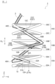
- FIG. 1 is a perspective view showing a cable bundle according to a first embodiment of the present invention.
- FIG. 2 is an enlarged side view of a portion of the cable bundle shown in FIG.
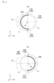
- FIG. 3(a) is a schematic plan view showing the position of a first intermediate portion in the circumferential direction of the cable bundle
- FIG. 3(b) is a schematic plan view showing the position of a second intermediate portion in the circumferential direction of the cable bundle.
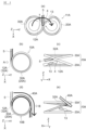
- 4(a) to 4(e) are diagrams showing a method of forming a first unit bundle of cables in the first embodiment of the present invention.
- 5(a) to 5(e) are diagrams showing a method of forming a second unit bundle of cables in the first embodiment of the present invention.
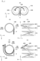
- FIG. 6(a) to 6(e) are diagrams showing a method for forming a third unit bundle of cables in the first embodiment of the present invention.
- FIG. 7 is a perspective view showing the configuration of the eight-shaped loops when the unit bundle in the second embodiment of the present invention is opened.
- FIG. 8 is a side view showing a cable bundle according to the second embodiment of the present invention, and corresponds to FIG.
- FIG. 9 is a development view of a portion of a cable bundle according to the third embodiment of the present invention.
- FIG. 10 is a diagram showing a cable bundle manufacturing apparatus according to the third embodiment of the present invention.
- Fig. 1 is a perspective view showing a cable bundle 1 in a first embodiment of the present invention
- Fig. 2 is an enlarged side view of a portion of the cable bundle 1 shown in Fig. 1.
- Fig. 3(a) is a schematic plan view showing the position of a middle portion 40A of the cable bundle 1 in the circumferential direction D1
- Fig. 3(b) is a schematic plan view showing the position of a middle portion 40B of the cable bundle 1 in the circumferential direction D1 .
- the container 50 is shown in a see-through manner to make it easier to understand the state inside the container 50.
- the white portion of the cable 2 indicates the front side of the cable 2
- the shaded portion of the cable 2 indicates the back side of the cable 2.
- the thick solid line portion of the cable 2 indicates the middle portions 40A, 40B, and 40C of the cable 2
- the thick dashed line portion of the cable 2 indicates the connection portions 12A, 12B, and 12C of the cable 2.
- the cable bundle 1 in this embodiment includes the cable 2 wound in a ring shape (tubular, coil shape) in the winding direction D2 , and is formed by winding a single continuous cable 2 by a winding method described later.
- This cable bundle 1 has a so-called drumless structure that does not have a winding core such as a drum or a reel.
- a specific example of the cable 2 can be an optical fiber cable, but is not limited to this.
- a metal cable for power transmission, communication, or a composite type that combines these may be used as the cable 2.
- the cable 2 in this embodiment does not have any connection point between one end 3 (e.g., the end (E end) of the cable 2 at the end where the winding ends) and the other end 4 (e.g., the end (S end) of the cable 2 at the end where the winding starts) (see FIG. 2), but a single continuous cable 2 may be configured by connecting multiple cables by, for example, fusion splicing, a connector, or the like.
- the cable bundle 1 is transported to the laying site in a state housed in a container 50 as shown in FIG. 1.
- the container 50 has a box-like shape, and an opening 52 is formed on the upper surface thereof.
- the cable 2 is supplied to the laying site by being sequentially unwound from one end 3 to the outside of the container 50 through the opening 52.
- the cable bundle 1 is arranged in the container 50 in a position (i.e., a "vertical position") in which the axial direction D3 of the cable bundle 1 is substantially parallel to the vertical direction (the Z direction in the figure).
- the container 50 is, for example, made of cardboard made of paper, but is not particularly limited thereto.
- the container 50 may be made of plastic cardboard made of a resin material such as polypropylene (PP), or may be made of a metal box.
- PP polypropylene
- this cable bundle 1 comprises a plurality of unit bundles 10A, 10B, 10C, etc. and a plurality of intermediate portions 40A, 40B, 40C, etc.
- Each unit bundle 10A, 10B, 10C, etc. is formed by winding the cable 2 in a figure of eight to form two circular loops and folding the two loops, as will be described in detail later.
- the plurality of unit bundles 10A, 10B, 10C, etc. are stacked vertically (Z direction in the figure).
- Each intermediate portion 40A, 40B, 40C, etc. is a portion of the cable 2 that is interposed between the unit bundles 10A, 10B, 10C, etc. Note that FIG. 2 shows only three unit bundles 10A, 10B, 10C on the other end 4 side of the cable 2, but in reality the cable bundle 1 comprises a large number of unit bundles.
- the unit bundle 10A includes a first ring 20A and a second ring 30A.
- the first and second rings 20A, 30A have substantially the same diameter, but the diameters of the first and second rings 20A, 30A may be different from each other.
- the first ring 20A is formed by winding the cable 2 in a "forward winding”.
- the second ring 30A is formed by winding the cable 2 in a "reverse winding”.
- forward winding refers to winding the cable 2 so that the start point of the loop is located on one side (e.g., the lower side) of the end point in the overlapping direction of the two loops that make up the unit bundle.
- reverse winding refers to winding the cable 2 so that the start point of the loop is located on the other side (e.g., the upper side) of the end point in the overlapping direction of the two loops.
- the cable 2 is wound so that the starting point 21A is located below the end point 22A in the overlapping direction D3 (Z direction in the figure) of the two loops 20A, 30A, so the winding method of this first loop 20A is "forward winding".
- the cable 2 is wound so that the starting point 31A is located above the end point 32A in the overlapping direction D3 (Z direction in the figure) of the two loops 20A, 30A, so the winding method of this second loop 30A is "reverse winding".
- the overlapping direction D3 (Z direction in the figure) of the two loops 20A, 30A corresponds to an example of the "second direction" in this aspect of the present invention.
- this unit bundle 10A is formed by winding in a figure of eight, the two loops 20A, 30A are connected to each other at the connection part 12A.
- the two loops 20A, 30A are connected to each other at the connection part 12A so that when this unit bundle 10A is opened, an eight-shaped loop 11A (see FIG. 4(a) described later) including the first and second loops 20A, 30A is formed.
- the unit bundle 10A is opened (see FIG. 4(a))
- the starting point 21A of the first loop 20A is located below the end point 22A of the first loop 20A
- the starting point 31A of the second loop 30A is also located below the end point 32A of the second loop 30A.
- the first loop 20A is defined by the cable 2 crossing at the start point 21A and the end point 22A of the first loop 20A
- the second loop 30A is defined by the cable 2 crossing at the start point 31A and the end point 32A of the second loop 30A. Therefore, when the first intersection defining the first loop 20A and the second intersection defining the second loop 30A overlap in the circumferential direction D1 of the cable bundle 1 , the connection portion 12A coincides with the first and second intersections in the circumferential direction D1 . On the other hand, when the first and second intersections are offset in the circumferential direction D1 of the cable bundle 1, the connection portion 12A is a portion of the cable 2 between the first and second intersections including the first and second intersections.
- the "figure of eight” in this embodiment includes a complete figure of eight shape in which the connection portion 12A has no length, and also includes a shape in which two loops 20A and 20B are connected by the connection portion 12A that has a length.
- the "figure eight” refers to the Arabic numeral "8.”
- the unit bundle 10B also includes a first loop 20B formed by winding the cable 2 in a forward direction and a second loop 30B formed by winding the cable 2 in a reverse direction.
- first loop 20B the cable 2 is wound so that the starting point 21B is located below the end point 22B in the overlapping direction D3 (Z direction in the figure) of the two loops 20B, 30B, so the winding method of this first loop 20B is "forward winding".
- the second loop 30B the cable 2 is wound so that the starting point 31B is located above the end point 32B in the overlapping direction D3 (Z direction in the figure) of the two loops 20B, 30B, so the winding method of this second loop 30B is "reverse winding".
- the two rings 20B, 30B are stacked in the vertical direction (Z direction in the figure) so that the second ring 30B is located above the first ring 20B.
- the unit bundle 10B is also formed by a figure-of-eight winding
- the two rings 20B, 30B are connected at the connection portion 12B.
- the two rings 20B, 30B are connected to each other at the connection portion 12B so that when the unit bundle 10B is opened, an eight-shaped ring 11B (see FIG. 5(a) described below) including the first and second rings 20B, 30B is formed.
- the starting point 21B of the first ring 20B is located below the end point 22B of the first ring 20B, and the starting point 31B of the second ring 30B is also located below the end point 32B of the second ring 30B.
- the unit bundle 10B is stacked on top of the unit bundle 10A.
- the unit bundles 10A and 10B are connected to each other via an intermediate portion 40A of the cable 2.
- the intermediate portion 40A is a portion of the cable 2 that is interposed between the unit bundles 10A and 10B, and is wound along the circumferential direction D1 of the cable bundle 1.
- This circumferential direction D1 of the cable bundle 1 corresponds to an example of the "first direction" in this aspect of the present invention.
- the length L1 of the intermediate portion 40A may be 1/4 to 3/4 of the circumferential length L2 of the second loop 30A ( L2 x 1/4 ⁇ L1 ⁇ L2 x 3/4), in which case the connection portion 12A of the unit bundle 10A and the connection portion 12B of the unit bundle 10B are offset within a range of 90 degrees to 270 degrees (90° ⁇ ⁇ 1 ⁇ 270°) in the circumferential direction D1 of the cable bundle 1.
- the length L1 of the intermediate portion 40A may be 1/3 to 2/3 of the circumferential length L2 of the second loop 30A ( L2 x 1/3 ⁇ L1 ⁇ L2 x 2/3), in which case the connection portion 12A of the unit bundle 10A and the connection portion 12B of the unit bundle 10B are offset within a range of 120 degrees to 240 degrees in the circumferential direction D1 of the cable bundle 1 (120° ⁇ ⁇ 1 ⁇ 240°).
- the unit bundle 10C also has a first loop 20C formed by winding the cable 2 in a forward direction, and a second loop 30C formed by winding the cable 2 in a reverse direction.
- the two loops 20C, 30C are stacked so that the second loop 30C is located above the first loop 20C in the vertical direction (Z direction in the figure).
- the unit bundle 10C is also formed by a figure-of-eight winding, the two loops 20C, 30C are connected at the connection portion 12C.
- the two loops 20C, 30C are connected to each other at the connection portion 12C so that when the unit bundle 10C is opened, a figure-of-eight-shaped loop 11C (see FIG.
- This unit bundle 10C is stacked on top of the unit bundle 10B. Moreover, these unit bundles 10B and 10C are connected via an intermediate portion 40B of the cable 2. This intermediate portion 40B is a portion of the cable 2 that is interposed between the unit bundles 10B and 10C, and is wound along the circumferential direction D1 of the cable bundle 1.
- the length L3 of the intermediate portion 40B may be 1/4 to 3/4 of the circumferential length L4 of the first loop 20B ( L4 x 1/4 ⁇ L3 ⁇ L4 x 3/4), in which case the connection portion 12B of the unit bundle 10B and the connection portion 12C of the unit bundle 10C are offset within a range of 90 degrees to 270 degrees in the circumferential direction D1 of the cable bundle 1 (90° ⁇ ⁇ 2 ⁇ 270°).
- the length L3 of the intermediate portion 40B may be 1/3 to 2/3 of the circumferential length L4 of the first loop 20B ( L4 x 1/3 ⁇ L3 ⁇ L4 x 2/3), in which case the connection portion 12B of the unit bundle 10B and the connection portion 12C of the unit bundle 10C are offset within a range of 120 degrees to 240 degrees in the circumferential direction D1 of the cable bundle 1 ( 120 ° ⁇ ⁇ 2 ⁇ 240°).
- a twist 13 is imparted to the unit bundle 10A near the end 4 on the winding start side.
- This twist 13 is imparted to the cable 2 by twisting the cable 2 one turn in a direction opposite to the twist caused by the intermediate portions 40A, 40B when the cable 2 is unwound from the cable bundle 1.
- this twist 13 is imparted to the cable 2 by twisting the cable 2 one turn in a direction opposite to the winding direction D2 (see FIG. 1) of the cable bundle 1 when the cable bundle 1 is viewed from the pull-out side (end portion 3 side) of the cable 2.
- This one-turn twist 13 of the unit bundle 10 can offset the twist caused by the two intermediate portions 40A, 40B corresponding to one revolution of the cable bundle 1 when the cable 2 is unwound from the cable bundle 1.
- the unit bundles above the unit bundle 10C shown in Fig. 2 among the multiple unit bundles are configured by alternating the above-mentioned unit bundles 10B and 10C (hereinafter simply referred to as "unit bundle 10B'" and “unit bundle 10C'”). These unit bundles 10B', 10C' are connected via the above-mentioned middle portion 40B, and the connection portions 12B, 12C of the unit bundles 10B', 10C' adjacent to each other in the overlapping direction D3 of the unit bundles (Z direction in the figure) are shifted in the circumferential direction D1 of the cable bundle 1.
- this intermediate portion 40C has a length that is half the circumferential length of the first loop 20C of the lower unit bundle 10C to which the intermediate portion 40C is connected. Therefore, the connection portions 12C and 12B of the unit bundles 10C and 10B' (or unit bundles 10C' and 10B') adjacent to each other in the overlapping direction D3 of the unit bundles (Z direction in the figure) are also shifted in the circumferential direction D1 of the cable bundle 1.
- a one-turn twist 13 is imparted to the two unit bundles 10B' and 10C'.
- the position where the twist 13 is applied in the cable bundle 1 is not limited to the vicinity of the end of the unit bundle.
- the twist 13 may be applied at any position in the unit bundle, or the twist 13 may be applied to the middle part connecting the unit bundles.
- the total number of rotations R of all the twists 13 applied to the entire cable bundle 1 is preferably equal to or less than the value obtained by dividing the total length L t of all the middle parts 40A, 40B, ... of the cable bundle 1 by the average circumference L 0 of the cable bundle 1 (R ⁇ L t /L 0 ), and it is more preferable that the number of rotations R is equal to the value obtained by dividing the total length L t of the middle parts 40A, 40B, ...
- the average circumference L 0 of the cable bundle 1 is a value obtained by dividing the total length of the cable 2 by the number of turns of the cable 2.
- Figures 4(a) to 6(e) are diagrams showing a method for forming unit bundle 10A of cable bundle 1 in the first embodiment of the present invention
- Figures 5(a) to 5(e) are diagrams showing a method for forming unit bundle 10B of cable bundle 1 in the first embodiment of the present invention
- Figures 6(a) to 6(e) are diagrams showing a method for forming unit bundle 10C of cable bundle 1 in the first embodiment of the present invention.
- Fig. 4(c) is a view of unit bundle 10A from direction A in Fig. 4(b), and Fig. 4(e) is a view of unit bundle 10A from direction B in Fig. 4(d).
- Fig. 5(c) is a view of unit bundle 10B from direction C in Fig. 5(b)
- Fig. 5(e) is a view of unit bundle 10B from direction D in Fig. 5(d).
- Fig. 6(c) is a view of unit bundle 10C from direction E in Fig. 6(b)
- Fig. 6(e) is a view of unit bundle 10C from direction F in Fig. 6(d).
- the cable 2 is arranged in an 8-shape to form a third loop 11A in an 8-shape.
- This third loop 11A has first and second loops 20A, 30A connected by a connection portion 12A.
- the cable 2 is wound around the first loop 20A so that the starting point 21A is located below the end point 22A, making the winding method for the first loop 20A "forward winding".
- the cable 2 is also wound around the second loop 30A so that the starting point 31A is located below the end point 32A. If the second loop 30A is then reversed, the winding method for the second loop 30A becomes "reverse winding".
- a twist 13 is formed in the first loop 20A near the end 4 of the cables 2.
- This twist 13 is imparted to the cables 2 by twisting the cables 2 one turn in a direction opposite to the winding direction D2 (see FIG. 1 ) of the cable bundle 1 when the cable bundle 1 is viewed from the pull-out side (end 3 side) of the cables 2.
- the winding direction D2 of the cable bundle 1 is clockwise, so that a twist 13 is imparted to the cables 2 such that the cable 2 is counterclockwise.
- the third loop 11A in the shape of a figure 8 is folded at the connection portion 12A, and the second loop 30A is placed on top of the first loop 20A to form the unit bundle 10A.
- a portion 5 of the cable 2 (a portion 5 of the cable 2 on the end portion 3 side of the end point 32A of the second loop 30A) is wound 180 degrees along the circumferential direction D1 of the cable bundle 1.
- This portion 5 of the cable 2 corresponds to the intermediate portion 40A between the unit bundles 10A and 10B.
- the portion of the cable 2 following the portion 5 is arranged in an 8-shape to form a third loop 11B in an 8-shape.
- This third loop 11B has first and second loops 20B, 30B connected by a connection portion 12B.
- the cable 2 is wound around the first loop 20B so that the starting point 21B is located below the end point 22B, and the winding method of the first loop 20B is "forward winding".
- the cable 2 is also wound around the second loop 30B so that the starting point 31B is located below the end point 32B. If the second loop 30B is then reversed, the winding method of the second loop 30B becomes "reverse winding". Note that no twist 13 is imparted to this third loop 11B.
- the first wheel 20B and the second wheel 30B are opposite in positional relationship compared to the first and second wheels 20A, 30A in the first tier third wheel 11A described above. That is, in the first tier third wheel 11A shown in FIG. 4(a), the first wheel 20A is located on the right side of the second wheel 30A, whereas in the second tier third wheel 11B shown in FIG. 5(a), the first wheel 20B is located on the left side of the second wheel 30B.
- the third loop 11B in the figure-8 shape is folded at the connection portion 12B, and the second loop 30B is placed on top of the first loop 20B to form the unit bundle 10B.
- a portion 6 of the cable 2 (a portion 6 of the cable 2 on the end portion 3 side of the end point 22B of the first loop 20B) is wound 180 degrees in the circumferential direction D1 of the cable bundle 1. This portion 6 of the cable 2 corresponds to the intermediate portion 40B between the unit bundles 10B and 10C.
- the portion of the cable 2 following the portion 6 is arranged in an 8-shape to form a third loop 11C in an 8-shape.
- This third loop 11C includes first and second loops 20C, 30C connected by a connection portion 12C.
- the cable 2 is wound around the first loop 20C so that the starting point 21C is located below the end point 22C, making the winding method of the first loop 20C "forward winding".
- the cable 2 is also wound around the second loop 30C so that the starting point 31C is located below the end point 32C. If the second loop 30C is then reversed, the winding method of the second loop 30C becomes "reverse winding". Note that no twist 13 is imparted to this third loop 11C either.
- the first wheel 20C and the second wheel 30C are reversed in positional relationship compared to the first and second wheels 20B, 30B in the second tier third wheel 11B described above. That is, in the second tier third wheel 11B shown in FIG. 5(a), the first wheel 20B is located on the left side of the second wheel 30B, whereas in the third tier third wheel 11C shown in FIG. 6(a), the first wheel 20C is located on the right side of the second wheel 30C.
- the third loop 11C in the figure-8 shape is folded at the connection portion 12C, and the second loop 30C is placed on top of the first loop 20C to form the unit bundle 10C.
- portion 7 of cable 2 (portion 7 of cable 2 on the end portion 3 side of end point 22C of first loop 20C) is wound 180 degrees in the circumferential direction D1 of cable bundle 1. Note that portion 7 of cable 2 corresponds to intermediate portion 40C between unit bundle 10C and the next unit bundle (the above-mentioned unit bundle 10B').
- the cable bundle 1 is formed by alternately forming unit bundles and intermediate portions.
- the unit bundles above unit bundle 10C shown in FIG. 2 among the multiple unit bundles are constructed by alternating unit bundles 10B' and unit bundles 10C', and these unit bundles 10B' and 10C' are connected via intermediate portion 40B of cable 2 described above. Also, unit bundle 10C' and the unit bundle 10B' above it are connected via intermediate portion 40C described above.
- the formation and stacking of unit bundles is repeated from the bottom up, but the method is not limited to this.
- all the unit bundles may be stacked.
- the third rings may be folded to form all unit bundles, and then all the unit bundles may be stacked.
- unit bundles may be formed without going through the figure-8 opening state.
- connection parts (e.g., 12A, 12B) of unit bundles (e.g., unit bundles 10A, 10B) adjacent to each other in the overlapping direction D3 (Z direction in the figure) of the unit bundles 10A, 10B, 10C, ... are shifted in the circumferential direction D1 of the cable bundle 1.
- the upper unit bundle (e.g., unit bundle 10B) functions as a weight relative to the rings of the lower unit bundle (e.g., rings 20A, 30A of unit bundle 10A), thereby suppressing the lifting up of the rings that are subsequently paid out (e.g., rings 20A, 30A of unit bundle 10A), and thus preventing the cable 2 from becoming entangled.
- FIG. 7 is a perspective view showing the configuration of the figure-8 ring 11 when the unit bundle 10 in the second embodiment of the present invention is opened.
- the starting point 21 of the first loop 20 is located below the end point 22 of the first loop 20.
- the end point 32 of the second loop 30 is located below the starting point 31 of the second loop 30 and the starting point 21 of the first loop 20, and a portion 8 of the cable 2 (a portion 8 of the cable 2 that is closer to the end 4 than the starting point 21 of the first loop 20) passes through the second loop 30.
- a cable bundle 1B shown in FIG. 8 is formed.
- the cable 2 is wound around the first loop 20B so that the starting point 21B is located above the end point 22B in the overlapping direction D 3 (Z direction in the figure) of the two loops 20B and 30B, so the winding method of the first loop 20A is "reverse winding".
- the cable 2 is also wound around the second loop 30B so that the starting point 31B is located above the end point 32B in the overlapping direction D 3 (Z direction in the figure) of the two loops 20B and 30B, so the winding method of the second loop 30B is "reverse winding".
- the winding methods of the first and second loops 20B and 30B are both "reverse winding".
- the first and second loops 20C and 30C are both wound in the "reverse winding" manner.
- connection portion of the unit bundle may have a length.
- a cable bundle 1C according to a third embodiment of the present invention will be described with reference to FIG. 9.
- FIG. 9 is an exploded view of a portion of cable bundle 1C according to the third embodiment of the present invention.
- the cable bundle 1C of this embodiment includes a plurality of unit bundles 10A, 10B, ... and a plurality of intermediate portions 40A, 40B, ....
- the cable 2 is twisted to form individual loops in sequence, and the loops are stacked in sequence to form the cable bundle 1C.
- FIG. 9 only illustrates two unit bundles 10A, 10B at the end 4 of the cable 2, but in reality the cable bundle 1C includes many unit bundles.
- FIG. 9 is an exploded view of the cable bundle 1C, it shows the unit bundles 10A, 10B in an open state, but in reality the multiple unit bundles 10A, 10B, ... are stacked vertically (Z direction in the figure).
- the unit bundle 10A includes a first loop 20A and a second loop 30A.
- the first loop 20A is formed by winding the cable 2 so that the starting point 21A is located above the end point 22A, and the winding method of the first loop 20A is "reverse winding".
- the second loop 30A is formed by winding the cable 2 so that the starting point 31A is located below the end point 32A, and the winding method of the second loop 30B is "forward winding".
- FIG. 9 shows the cable bundle 1C in an open state, and therefore the starting point 31A of the second loop 30A is located above the end point 32A.
- the two loops 20A, 30A are stacked so that the second loop 30A is located above the first loop 20A in the vertical direction (Z direction in the figure).
- the two loops 20A, 30A are connected via a connection part 12A so that when the unit bundle 10A is opened, an eight-shaped loop 11A is formed with the first and second loops 20A, 30A.
- connection portion 12A of the unit bundle 10A is a portion of the cable 2 between the intersections 23A and 33A of the first and second loops 20A and 30A, so that the connection portion 12A of this embodiment has a predetermined length.
- This connection portion 12A is wound along the circumferential direction D1 of the cable bundle 1C.
- the length of this connection portion 12A has a length corresponding to the central angle ⁇ 3 in the circumferential direction D1 of the cable bundle 1C.
- the central angle defining the length of this connection portion is preferably 120° or less.
- the unit bundle 10B also has a first loop 20B and a second loop 30B.
- the first loop 20B is formed by winding the cable 2 so that the starting point 21B is located above the end point 22B, so the winding method of this second loop 30B is "reverse winding”.
- the second loop 30B is also formed by winding the cable 2 so that the starting point 31B is located above the end point 32B, so the winding method of this second loop 30B is also "reverse winding”.
- Figure 9 shows the cable bundle 1C in an open state, so the starting point 21B of the first loop 20B is located below the end point 22B, and the starting point 31B of the second loop 30B is also located below the end point 32B.
- the two rings 20B, 30B are stacked so that the second ring 30B is positioned above the first ring 20B in the vertical direction (Z direction in the figure).
- the two rings 20B, 30B are connected via a connection part 12B so that when the unit bundle 10B is opened, an eight-shaped ring 11B including the first and second rings 20B, 30B is formed.
- the second ring 30B may be wound in a "normal winding" manner.
- connection portion 12B of the unit bundle 10B is a portion of the cable 2 between the intersections 23B and 33B of the first and second loops 20B and 30B, so that the connection portion 12B of this embodiment has a predetermined length.
- This connection portion 12B is wound along the circumferential direction D1 of the cable bundle 1C.
- connection portion 12B has a length corresponding to the central angle ⁇ 4 in the circumferential direction D1 of the cable bundle 1C.
- the unit bundle 10B is stacked on the unit bundle 10A. At this time, the starting point 31B and the end point 32B of the second loop 30B of the unit bundle 10B are located above the starting point 21A and the end point 22A of the first loop 20A of the unit bundle 10A.
- the unit bundles 10A and 10B are connected via the middle part 40A of the cable 2.
- the middle part 40A is a part of the cable 2 between the end point 32B of the second loop 30A of the unit bundle 10A and the starting point 21B of the first loop 20B of the unit bundle 10B, and is wound along the circumferential direction D1 of the cable bundle 1C.
- the length of the middle part 40A has a length corresponding to the central angle ⁇ 5 in the circumferential direction D1 of the cable bundle 1C.
- connection parts 12A, 12B and the intermediate part 40A of the unit bundles 10A, 10B each have a length corresponding to 120° in the circumferential direction D1 of the cable bundle 1C, so that the sum of these forms one loop along the circumferential direction D1 of the cable bundle 1C.
- the winding of the loop formed by the connection parts 12A, 12B and the intermediate part 40A and the winding of the second loop 30B of the unit bundle 10A are "forward winding"
- the winding of the first loop 20A of the unit bundle 10A and the winding of the first loop 20B of the unit bundle 10B are "reverse winding"
- the number of "forward winding" loops and the number of "reverse winding” loops are the same. Therefore, since the twist is zero in these four loops, it is not necessary to form the twist 13 described in the first embodiment in the cable bundle 1C.
- the total number of the first and second loops connected via the connection parts and the intermediate part is not particularly limited to the above, as long as it is an odd number.
- the winding method of each loop is not particularly limited to the above, as long as the number of "forward winding" loops and the number of "reverse winding" loops are the same.
- the lengths of the connection parts and the intermediate part that form one loop along the circumferential direction D1 of the cable bundle 1C do not have to be equal.
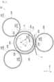
- FIG. 10 is a diagram showing a manufacturing device 60 for a cable bundle 1C according to a third embodiment of the present invention.
- the manufacturing device 60 in this embodiment includes a holding device 61, a twisting device 62, a fixing device 63, a rotating device 64, and a control device 65.
- the holding device 61 holds a drum 611 around which the cable 2 is wound.
- the drum 611 is held by the holding device 61 so as to be rotatable about a central axis RA -1 of the drum 611.
- the drum 611 passively rotates as the cable 2 is pulled out by the caterpillar 621 of the twisting device 62, but the holding device 61 may be provided with a drive device that drives the drum 611 to rotate about the rotation axis RA -1 of the drum 611.
- the drive device works in conjunction with the caterpillar 621 of the twisting device 62 to actively feed out the cable 2 from the drum 611.
- the holding device 61 may also include a rotation device 612 that rotates the drum 611 about a rotation axis RA2 that is substantially parallel to the payout direction D4 of the cable 2 from the drum 611. This makes it possible to easily remove the twist from the cable 2 when a twist occurs in the portion of the cable 2 between the drum 611 and the twisting device 62.
- the rotation axis RA2 is also an axis that is substantially perpendicular to the rotation axis RA1 of the drum 611.
- the rotation axis RA2 corresponds to an example of a "second axis" in this aspect of the present invention.
- the twisting device 62 includes a pair of caterpillars 621, a frame 625, and a rotating device 626.
- Each caterpillar 621 includes a pair of pulleys 622, an endless belt 623 looped around the pulley 622, and a driving device 624 for rotating the pulley 622.
- the pair of caterpillars 621 are arranged so that the belts 623 are in close contact with each other, and the cable 2 supplied from the drum 611 can be sandwiched between the belts 623.
- the driving device 624 includes a motor and a gear box for rotating the pulley 622, and by driving the caterpillars 621, it is possible to pull out the cable 2 from the drum 611 and push out the cable 2 from the twisting device 62.
- This pair of caterpillars 621 corresponds to an example of a "sending device" in this aspect of the present invention.
- the pair of caterpillars 621 are housed in a frame 625.
- the rotating device 626 includes a motor, a gear box, and the like for rotating the frame 625.
- the rotating device 626 is capable of twisting the cable 2, which is sandwiched between the pair of caterpillars 621, by rotating the frame 625 about the axial direction of the cable 2.
- the rotating device 626 is capable of rotating the frame 625 360° in one rotation direction D5 , and is also capable of rotating the frame 625 360° in the other rotation direction D6 .
- the one rotation direction D5 corresponds to an example of a "third direction" in this aspect of the present invention
- the other rotation direction D6 corresponds to an example of a "fourth direction" in this aspect of the present invention.
- the configuration of the twisting device 62 is not particularly limited to the above, so long as it has a mechanism for feeding out the cable 2 and a function for twisting the cable 2.
- the twisting device 62 may have a gripping part that grips the cable and a moving part that moves the gripping part along the axial direction of the cable 2, and the gripping part may have a plurality of rollers that can twist the cable.
- the function of feeding out the cable 2 and the function of twisting the cable 2 may be achieved by devices that are independent of each other.
- the fixing device 63 is a device that fixes the cable 2 sent out from the twisting device 62. Although not limited to this, a specific example of this fixing device 63 is a clamp that clamps and fixes the fixed position FP of the cable 2 using an air cylinder or the like. This fixing device 63 fixes the movement of the cable 2 along the axial direction at the fixed position FP on the cable 2.
- This fixed position FP is a position on the cable 2 that is a predetermined distance away from the twisting device 62. This predetermined distance is a distance that allows one loop 15 of the cable 2 (e.g., the first loop 20A) to be formed between the fixed position FP and the twisting device 62.
- the caterpillar 621 of the twisting device 62 sends out the cable 2 toward the fixed position FP, and when the rotating device 626 of the twisting device 62 rotates the cable 2 in one rotation direction D5 , a "reverse winding" loop is formed.
- a "forward winding" loop is formed.
- the rotating device 64 includes a mounting table 641 and a driving device 642.
- the rings 15 formed by the twisting device 62 are placed on the mounting table 641 and stacked.
- the mounting table 641 includes a mounting surface on which the rings 15 of the cable 2 are placed.
- the driving device 642 includes a motor, a gear box, and the like for rotating the mounting surface of the mounting table 641.
- the driving device is capable of rotating the mounting surface of the mounting table 641 around a rotation axis RA 3 that is substantially parallel to the normal direction of the mounting table 641.
- the rotation axis RA 3 corresponds to an example of the "first axis" in the aspect of the present invention.
- the driving device 642 rotates the mounting surface of the mounting table 641 only counterclockwise, but the driving device 642 may rotate the mounting surface of the mounting table 641 in both clockwise and counterclockwise directions.
- the control device 65 is, for example, configured with a computer.
- This computer is an electronic calculator equipped with a CPU (processor), a main memory device (RAM, etc.), a secondary memory device (hard disk, SSD, etc.), and an interface, etc., although not specifically shown.
- This control device 65 is controllably connected to the drive device 624 and rotation device 626 of the twisting device 62 described above, the fixing device 63, and the drive device 642 of the rotation device 64. These controls are functionally realized, for example, by the control device 65 executing a program. Note that this control device 65 may be configured with a circuit board instead of a computer.
- the control device 65 sends a control signal to the fixing device 63, and the fixing device 63 clamps the fixing position FP on the cable 2.
- the fixing device 63 fixes the movement of the cable 2 along the axial direction at the fixing position FP on the cable 2.
- control device 65 sends a control signal to the drive device 624 of the twisting device 62, and the caterpillar 621 sends out a predetermined amount of the cable 2 from the twisting device 62.
- This predetermined amount is the length equivalent to one loop 15 of the cable 2, and is a value input in advance to the control device 65.
- the control device 65 transmits a control signal to the rotation device 626 of the twisting device 62, and the rotation device 626 rotates the frame 625 360° in one rotation direction D5 to twist the cable 2, thereby forming a "reverse-wound" first loop 20A.
- This first loop 20A is placed on the placement table 641 of the rotation device 64.
- the twisting device 62 may twist the cable 2 while feeding out a predetermined amount of the cable 2.
- the control device 65 transmits a control signal to the fixing device 63, and the fixing device 63 releases the cable 2 to release the fixing of the cable 2.
- the control device 65 transmits a control signal to the driving device 642 of the rotating device 64 and the driving device 624 of the twisting device 62.
- the driving device 642 rotates the mounting surface of the mounting table 641 by a central angle ⁇ 3 , and at the same time, the caterpillar 621 feeds out a predetermined amount of the cable 2 from the twisting device 62.
- This predetermined amount is a length corresponding to the central angle ⁇ 3 in the circumferential direction D 1 of the cable bundle 1C, and is a value input in advance to the control device 65.
- the connection portion 12A of the unit bundle 10A in the cable bundle 1C is formed.
- the second loop 30A of the unit bundle 10A is formed in the same manner as the formation of the first loop 20A described above.
- the rotation device 626 rotates the frame 625 360° in the other rotation direction D6 to twist the cable 2, thereby forming the second loop 30A with a "forward winding".
- This second loop 30A is placed on the placement table 641 of the rotation device 64, and the unit bundle 10A is formed.
- the twisting device 62 may twist the cable 2 while feeding out a predetermined amount of the cable 2.
- the control device 65 transmits a control signal to the fixing device 63, and the fixing device 63 releases the cable 2 to release the fixing of the cable 2.
- the control device 65 transmits a control signal to the driving device 642 of the rotating device 64 and the driving device 624 of the twisting device 62.
- the driving device 642 rotates the mounting surface of the mounting table 641 by a central angle ⁇ 5 , and at the same time, the caterpillar 621 feeds out a predetermined amount of the cable 2 from the twisting device 62.
- This predetermined amount is a length corresponding to the central angle ⁇ 5 in the circumferential direction D 1 of the cable bundle 1C, and is a value input in advance to the control device 65.
- the intermediate portion 40A between the unit bundles 10A and 10B is formed in the cable bundle 1C.
- unit bundles and intermediate portions are alternately formed to form cable bundle 1C. If a twist occurs in cable 2 between drum 611 and twisting device 62, the twist can be removed by rotating drum 611 using rotation device 612 described above.
- the driving device 642 of the rotating device 64 rotates the mounting surface of the mounting table 641 on which the loop 15 of the cable 2 is placed, so that a cable bundle 1C having connection portions 12A, 12B that are offset in the circumferential direction D1 can be manufactured.
- the manufacturing apparatus 60 may also include a measuring device 66 that measures the length of the cable 2 sent out by the twisting device 62.
- the control device 65 may control the drive device 624 of the twisting device 62 based on the measurement results of the measuring device 66 so that the caterpillar 621 sends out a predetermined amount of the cable 2 from the twisting device 62.
- a specific example of such a measuring device 66 is an encoder.
- the length of the cable 2 sent out from the twisting device 62 may be measured by the measuring device 66 to perform quality control of the cable bundle 1.
- the cable bundle 1 shown in FIG. 1 may also be manufactured using the manufacturing apparatus 60 described above.
- the manufacturing apparatus 60 includes an additional fixing device 67 in addition to the fixing device 63 described above.
- This additional fixing device 67 has a similar configuration to the fixing device 63 described above.
- the fixing device 63 is used to form the first loop
- the additional fixing device 67 is used to form the second loop.
- the cable bundle 1 has a drumless structure that does not have a winding core, but is not particularly limited to this.
- the cable bundle 1 may have a winding core, or the cable bundle 1 may be formed around a payout guide pin.
- multiple unit bundles 10A, 10B, 10C, ... are stacked in a direction perpendicular to the radial direction (unit bundle stacking direction D3 (Z direction in the figure)), but this is not particularly limited.
- unit bundle stacking direction D3 Z direction in the figure
- by appropriately changing the size of the diameter of the rings constituting each unit bundle multiple unit bundles having different diameters arranged on the same plane may be stacked in the stacking direction D3 .
- another unit bundle having a diameter larger than the diameter of the unit bundle may be stacked in the stacking direction D3 on the outside of the multiple unit bundles stacked in the stacking direction D3 .
- the connection parts of the unit bundles may be shifted in the circumferential direction D1 of the cable bundle 1.
- the first intersection point and the second intersection point may be shifted in the circumferential direction D1 of the cable bundle 1.
- Twisting device 621 Caterpillar 622: Pulley 623: Belt 624: Driving device 625: Frame 626: Rotating device 63: Fixing device 64: Rotating device 641: Placement table 642: Driving device 65: Control device 66: Measuring device 67: Fixing device
Landscapes
- Storage Of Web-Like Or Filamentary Materials (AREA)
Abstract
A cable bundle 1 comprises a plurality of bundle units 10A-10C stacked in a second direction D3 orthogonal to a first direction that is the circumferential direction D1 of the cable bundle 1. The bundle units 10A-10C are respectively provided with first loops 20A-20C and second loops 30A-30C stacked in the second direction D3. The first loops 20A-20C and second loops 30A-30C are connected to each other by using connection parts 12A-12C such that figure-eight-shaped loops comprising the first and second loops are formed when the bundle units are opened. The connection parts 12A-12C of the bundle units 10A-10C that are adjacent in the second direction D3 are offset in the first direction D1.
Description
本発明は、ケーブル束、ケーブル束の製造方法、及び、ケーブル束の製造装置に関するものである。
文献の参照による組み込みが認められる指定国については、2022年11月24日に日本国に出願された特願2022-187748に記載された内容を参照により本明細書に組み込み、本明細書の記載の一部とする。 The present invention relates to a cable bundle, a method for manufacturing a cable bundle, and an apparatus for manufacturing a cable bundle.
For designated states in which incorporation by reference of literature is permitted, the contents described in Patent Application No. 2022-187748 filed in Japan on November 24, 2022 are incorporated by reference into this specification and made a part of the description of this specification.
ケーブルの巻き方として、ケーブルを時計廻り及び反時計廻りに交互に捻って輪を作りながら当該ケーブルを巻き取る、所謂「8の字巻き」が知られている(例えば、特許文献1参照)。この「8の字巻き」では、一つ目の輪と二つ目の輪とを解いてケーブルを伸ばす際に、一つ目の輪(二つ目の輪)を繰り出す時に発生する螺旋状の捻りが二つ目の輪(一つ目の輪)を作る際に付与された捻りを打ち消すため、ケーブルに捻りが発生しない。
A known method of winding a cable is the so-called "figure-of-eight winding," in which the cable is alternately twisted clockwise and counterclockwise to create loops while winding the cable (see, for example, Patent Document 1). With this "figure-of-eight winding," when the first loop and the second loop are unwound and the cable is extended, the spiral twist that occurs when the first loop (second loop) is unwound cancels the twist that was imparted when the second loop (first loop) was made, so no twist occurs in the cable.
ケーブルを上記の「8の字巻き」により連続的に巻いた場合、ケーブルの巻き方向においてケーブルの交差部が重なる。このため、ケーブルの曲げ剛性が強い場合、ケーブル束からケーブルを繰り出す際に、後に繰り出される輪が浮き上がり、ケーブルが絡まることでキンクが発生してしまう場合がある。特に、ケーブル束を容器に収容して当該容器の開口からケーブルを繰り出す場合に、この現象は頻発する傾向がある。
When a cable is wound continuously using the "figure-of-eight winding" described above, the intersections of the cable overlap in the winding direction. For this reason, if the cable has a high bending stiffness, when the cable is unwound from the cable bundle, the loop that is unwound later may float up, causing the cable to become tangled and resulting in a kink. This phenomenon tends to occur frequently, particularly when the cable bundle is stored in a container and the cable is unwound from the opening of the container.
本発明が解決しようとする課題は、輪の浮き上がりを抑制することが可能なケーブル束、ケーブル束の製造方法、及び、ケーブル束の製造装置を提供することである。
The problem that the present invention aims to solve is to provide a cable bundle that can prevent the rings from floating up, a method for manufacturing the cable bundle, and an apparatus for manufacturing the cable bundle.
[1]本発明の態様1は、巻かれたケーブルを備えたケーブル束であって、前記ケーブル束は、前記ケーブル束の周方向である第1の方向に対して直交する第2の方向に重ねられた複数の単位束を備え、それぞれの前記単位束は、前記第2の方向に重ねられた第1及び第2の輪を備え、前記第1及び第2の輪は、前記単位束を開いた場合に前記第1及び前記第2の輪を備えた8の字状の輪が形成されるように、接続部で相互に接続されており、前記第2の方向に隣り合う前記単位束が有する前記接続部は、前記第1の方向においてずれているケーブル束である。
[1] Aspect 1 of the present invention is a cable bundle with a wound cable, the cable bundle comprising a plurality of unit bundles stacked in a second direction perpendicular to a first direction which is the circumferential direction of the cable bundle, each of the unit bundles comprising first and second loops stacked in the second direction, the first and second loops being interconnected at a connection such that when the unit bundle is opened, an eight-shaped loop is formed comprising the first and second loops, and the connection parts of the unit bundles adjacent to each other in the second direction are offset in the first direction.
[2]本発明の態様2は、態様1のケーブル束において、前記第2の方向に隣り合う前記単位束が有する前記接続部は、前記第1の方向において90度~270度の範囲内でずれているケーブル束であってもよい。
[2] Aspect 2 of the present invention may be a cable bundle according to aspect 1, in which the connection portions of the unit bundles adjacent to each other in the second direction are offset in the first direction within a range of 90 degrees to 270 degrees.
[3]本発明の態様3は、態様1又は2のケーブル束において、それぞれの前記単位束は、前記第1及び前記第2の輪を備えた8の字状の輪を前記接続部で折り畳むことで形成されているケーブル束であってもよい。
[3] Aspect 3 of the present invention may be a cable bundle according to aspect 1 or 2, in which each of the unit bundles is formed by folding an eight-shaped loop having the first and second loops at the connection portion.
[4]本発明の態様4は、態様1~3のいずれか一つのケーブル束において、前記ケーブル束は、前記単位束の間に介在して前記単位束同士を接続する中間部分を備えており、前記中間部分は、前記第2の方向に隣り合う前記単位束が有する前記接続部が前記第1の方向においてずれるように、前記第1の方向に沿って巻かれているケーブル束であってもよい。
[4] Aspect 4 of the present invention is a cable bundle according to any one of aspects 1 to 3, in which the cable bundle has an intermediate portion interposed between the unit bundles to connect the unit bundles, and the intermediate portion may be a cable bundle wound along the first direction such that the connection portions of the unit bundles adjacent in the second direction are shifted in the first direction.
[5]本発明の態様5は、態様4のケーブル束において、前記中間部分は、前記第2の方向に隣り合う前記単位束が有する前記接続部が前記第1の方向において90度~270度の範囲内でずれるように、前記第1の方向に沿って巻かれているケーブル束であってもよい。
[5] A fifth aspect of the present invention may be a cable bundle according to the fourth aspect, in which the intermediate portion is wound along the first direction such that the connection portions of the unit bundles adjacent to each other in the second direction are shifted in the first direction within a range of 90 degrees to 270 degrees.
[6]本発明の態様6は、態様4又は5のケーブル束において、前記中間部分は、前記中間部分に接続された前記第1又は前記第2の輪の周長に対して1/4~3/4の長さを有しているケーブル束であってもよい。
[6] A sixth aspect of the present invention may be a cable bundle according to the fourth or fifth aspect, in which the intermediate portion has a length that is 1/4 to 3/4 of the circumference of the first or second loop connected to the intermediate portion.
[7]本発明の態様7は、態様1~6のいずれか一つのケーブル束において、前記複数の単位束は、第1の単位束と、前記第1の単位束に重ねられた第2の単位束と、前記第2の単位束に重ねられた第3の単位束と、を含み、前記ケーブル束は、前記第1の単位束と前記第2の単位束との間に介在して、前記第1の単位束と前記第2の単位束とを接続する第1の中間部分と、前記第2の単位束と前記第3の単位束との間に介在して、前記第2の単位束と前記第3の単位束とを接続する第2の中間部分と、を備え、前記第1及び前記第2の中間部分は、前記第1の方向に沿って巻かれており、前記第1の中間部分と前記第2の中間部分とは、前記第1の方向においてずれているケーブル束であってもよい。
[7] Aspect 7 of the present invention is a cable bundle according to any one of aspects 1 to 6, in which the multiple unit bundles include a first unit bundle, a second unit bundle overlapped on the first unit bundle, and a third unit bundle overlapped on the second unit bundle, and the cable bundle includes a first intermediate portion interposed between the first unit bundle and the second unit bundle and connecting the first unit bundle and the second unit bundle, and a second intermediate portion interposed between the second unit bundle and the third unit bundle and connecting the second unit bundle and the third unit bundle, the first and second intermediate portions being wound along the first direction, and the first intermediate portion and the second intermediate portion being offset in the first direction.
[8]本発明の態様8は、態様1~7のいずれか一つのケーブル束において、前記ケーブル束は、前記単位束の間に介在して前記単位束同士を接続すると共に、前記第1の方向に沿って巻かれた中間部分を備えており、前記ケーブルは、前記ケーブルを繰り出したときに前記中間部分によって生じる捻りとは反対の方向の捻りが付与されているケーブル束であってもよい。
[8] Aspect 8 of the present invention is a cable bundle according to any one of aspects 1 to 7, in which the cable bundle includes an intermediate portion interposed between the unit bundles to connect the unit bundles and wound along the first direction, and the cable is twisted in a direction opposite to the twist caused by the intermediate portion when the cable is unwound.
[9]本発明の態様9は、態様8のケーブル束において、前記ケーブルに付与された前記捻りの回転数は、前記中間部分の長さの合計を前記ケーブル束の平均周長で除算することで得られる値以下であるケーブル束であってもよい。
[9] A ninth aspect of the present invention may be a cable bundle according to the eighth aspect, in which the number of twisting turns imparted to the cables is equal to or less than a value obtained by dividing the total length of the intermediate portions by the average circumference of the cable bundle.
[10]本発明の態様10は、態様1~7のいずれか一つのケーブル束において、前記接続部は、前記第1の輪の第1の交差点と前記第2の輪の第2の交差点との間の前記ケーブルの部分であり、前記第1の方向に沿って巻かれているケーブル束であってもよい。
[10] Aspect 10 of the present invention is a cable bundle according to any one of aspects 1 to 7, in which the connection portion is a portion of the cable between a first intersection of the first loop and a second intersection of the second loop, and the cable bundle may be wound along the first direction.
[11]本発明の態様11は、態様10のケーブル束において、前記第2の方向に隣り合う複数の前記単位束が備える前記接続部と、前記単位束同士を接続する中間部分とが、前記第1の方向に沿った1周を形成しているケーブル束であってもよい。
[11] Aspect 11 of the present invention may be a cable bundle according to aspect 10, in which the connection portions of the unit bundles adjacent to each other in the second direction and an intermediate portion connecting the unit bundles form one loop along the first direction.
[12]本発明の態様12は、態様1~11のいずれか一つのケーブル束において、前記第1の輪は、正巻き、又は、前記正巻きとは反対の逆巻きで前記ケーブルを巻くことで形成され、前記第2の輪は、前記逆巻き、又は、前記正巻きで前記ケーブルを巻くことで形成されているケーブル束であってもよい。
[12] Aspect 12 of the present invention may be a cable bundle according to any one of aspects 1 to 11, in which the first loop is formed by winding the cable in a forward winding or a reverse winding opposite to the forward winding, and the second loop is formed by winding the cable in the reverse winding or the forward winding.
[13]本発明の態様13は、態様1~12のいずれか一つのケーブル束において、前記単位束は、前記ケーブルの繰り出し時に前記単位束に起因した捻じれが前記ケーブルに発生しないように形成されているケーブル束であってもよい。
[13] Aspect 13 of the present invention may be a cable bundle according to any one of aspects 1 to 12, in which the unit bundle is formed so that twisting due to the unit bundle does not occur in the cable when the cable is unwound.
[14]本発明の態様14は、巻かれたケーブルを備えたケーブル束を製造するケーブル束の製造方法であって、接続部で接続されていると共に相互に重ねられた第1の輪と第2の輪をそれぞれ備えた複数の単位束を形成する第1の工程と、前記ケーブル束の周方向である第1の方向において前記接続部が相互にずれるように、前記複数の単位束を重ねる第2の工程と、を備え、前記第1及び第2の輪は、前記単位束を開いた場合に前記第1及び前記第2の輪を備えた8の字状の輪が形成されるように、前記接続部で相互に接続されているケーブル束の製造方法である。
[14] Aspect 14 of the present invention is a method for manufacturing a cable bundle having a wound cable, comprising: a first step of forming a plurality of unit bundles, each of which has a first loop and a second loop that are connected at a connection portion and overlapped with each other; and a second step of overlapping the plurality of unit bundles such that the connection portions are offset from each other in a first direction, which is the circumferential direction of the cable bundle, and the first and second loops are connected to each other at the connection portions such that an eight-shaped loop is formed with the first and second loops when the unit bundle is opened.
[15]本発明の態様15は、態様14のケーブル束の製造方法であって、前記第1の工程は、前記ケーブルを8の字状に配置することで、前記接続部で接続された前記第1の輪と前記第2の輪をそれぞれ備えた複数の第3の輪を形成することと、それぞれの前記第3の輪を前記接続部で折り畳んで、前記第1及び前記第2の輪を重ねることで、複数の前記単位束を形成することと、を含むケーブル束の製造方法であってもよい。
[15] Aspect 15 of the present invention may be the method for manufacturing a cable bundle of aspect 14, in which the first step includes forming a plurality of third loops, each of which includes the first loop and the second loop connected at the connection portion, by arranging the cables in an eight-shape, and folding each of the third loops at the connection portion to overlap the first and second loops to form a plurality of the unit bundles.
[16]本発明の態様16は、態様14のケーブル束の製造方法であって、前記第1の工程は、前記ケーブルを第3の方向に捻ることで、前記第1の輪を形成することと、前記ケーブルを前記第3の方向とは反対の第4の方向に捻ることで、前記第2の輪を形成することと、前記第1の輪と前記第2の輪を重ねることで、前記単位束を形成することと、を含むケーブル束の製造方法であってもよい。
[16] Aspect 16 of the present invention may be the method for manufacturing a cable bundle of aspect 14, in which the first step includes forming the first loop by twisting the cable in a third direction, forming the second loop by twisting the cable in a fourth direction opposite to the third direction, and overlapping the first loop and the second loop to form the unit bundle.
[17]本発明の態様17は、態様14~16のいずれか一つのケーブル束の製造方法において、前記第2の工程は、相互に隣り合う前記単位束が有する前記接続部が前記第1の方向において90度~270度の範囲内でずれるように、前記単位束を重ねることを含むケーブル束の製造方法であってもよい。
[17] Aspect 17 of the present invention may be a method for manufacturing a cable bundle according to any one of aspects 14 to 16, in which the second step includes stacking the unit bundles so that the connection portions of the adjacent unit bundles are shifted in the first direction within a range of 90 degrees to 270 degrees.
[18]本発明の態様18は、態様14~17のいずれか一つのケーブル束の製造方法において、前記ケーブル束は、前記単位束の間に介在して前記単位束同士を接続する中間部分を備え、前記第2の工程は、相互に隣り合う前記単位束が有する前記接続部が前記第1の方向においてずれるように、前記中間部分を前記第1の方向に沿って巻くことを含むケーブル束の製造方法であってもよい。
[18] Aspect 18 of the present invention may be a method for manufacturing a cable bundle according to any one of aspects 14 to 17, in which the cable bundle has an intermediate portion interposed between the unit bundles and connecting the unit bundles, and the second step includes winding the intermediate portion along the first direction so that the connection portions of the unit bundles adjacent to each other are shifted in the first direction.
[19]本発明の態様19は、態様18のケーブル束の製造方法において、前記第2の工程は、相互に隣り合う前記単位束が有する前記接続部が前記第1の方向において90度~270度の範囲内でずれるように、前記中間部分を前記第1の方向に沿って巻くことを含むケーブル束の製造方法であってもよい。
[19] Aspect 19 of the present invention may be the method for manufacturing a cable bundle according to aspect 18, wherein the second step includes winding the intermediate portion along the first direction such that the connection portions of the adjacent unit bundles are shifted in the first direction within a range of 90 degrees to 270 degrees.
[20]本発明の態様20は、態様14~19のいずれか一つのケーブル束の製造方法において、前記中間部分は、前記中間部分に接続された前記第1又は前記第2の輪の周長に対して1/4~3/4の長さを有しているケーブル束の製造方法であってもよい。
[20] Aspect 20 of the present invention may be a method for manufacturing a cable bundle according to any one of aspects 14 to 19, in which the intermediate portion has a length that is 1/4 to 3/4 of the circumference of the first or second loop connected to the intermediate portion.
[21]本発明の態様21は、巻かれたケーブルを備えたケーブル束の製造装置であって、前記ケーブル上の固定位置で前記ケーブルの軸方向に沿った移動を固定する固定装置と、前記固定位置に向かって前記ケーブルを送り出す送出装置と、前記送出装置が送り出した前記ケーブルを捻ることで、前記ケーブルの輪を形成する捻回装置と、前記捻回装置によって形成された前記輪が載置されて積み重ねられる載置面を有し、前記載置面の法線方向に実質的に平行な第1の軸を中心として前記載置面を回転させる第1の回転装置と、を備えたケーブル束の製造装置である。
[21] Aspect 21 of the present invention is a cable bundle manufacturing apparatus having a wound cable, the cable bundle manufacturing apparatus comprising: a fixing device that fixes the movement of the cable along the axial direction at a fixed position on the cable; a feeding device that feeds out the cable toward the fixed position; a twisting device that forms a loop of the cable by twisting the cable fed out by the feeding device; and a first rotating device that has a mounting surface on which the loops formed by the twisting device are placed and stacked, and rotates the mounting surface around a first axis that is substantially parallel to the normal direction of the mounting surface.
[22]本発明の態様22は、態様21のケーブル束の製造装置であって、前記捻回装置は、前記ケーブルを第3の方向に捻ることで第1の輪を形成し、前記ケーブルを前記第3の方向とは反対の第4の方向に捻ることで第2の輪を形成するケーブル束の製造装置であってもよい。
[22] Aspect 22 of the present invention may be the cable bundle manufacturing apparatus of aspect 21, in which the twisting device forms a first loop by twisting the cable in a third direction, and forms a second loop by twisting the cable in a fourth direction opposite to the third direction.
[23]本発明の態様23は、態様21又は22のケーブル束の製造装置であって、前記ケーブルを供給するドラムを、前記ドラムから前記ケーブルを送り出す方向に実質的に平行な第2の軸を中心として回転させる第2の回転装置を備えたケーブル束の製造装置であってもよい。
[23] Aspect 23 of the present invention may be the cable bundle manufacturing apparatus of aspect 21 or 22, further comprising a second rotation device that rotates the drum that supplies the cables about a second axis that is substantially parallel to the direction in which the cables are fed from the drum.
本発明では、第2の方向に隣り合う単位束が有する接続部が第1の方向においてずれているので、後に繰り出される輪が浮き上がりを抑制することができる。また、本発明では、ケーブルの輪が載置された載置面を第1の回転装置が回転させるので、第1の方向においてずれた上記の接続部を備えたケーブル束を製造することができる。
In the present invention, the connection parts of unit bundles adjacent to each other in the second direction are offset in the first direction, so that the loop that is subsequently unwound can be prevented from floating up. Also, in the present invention, the first rotating device rotates the support surface on which the cable loop is placed, so that a cable bundle having the above-mentioned connection parts that are offset in the first direction can be manufactured.
以下、本発明の実施形態を図面に基づいて説明する。
Below, an embodiment of the present invention will be described with reference to the drawings.
図1は本発明の第1実施形態におけるケーブル束1を示す斜視図であり、図2は図1に示すケーブル束1の一部を拡大した側面図である。また、図3(a)はケーブル束1の周方向D1における中間部分40Aの位置を示す概略平面図であり、図3(b)はケーブル束1の周方向D1における中間部分40Bの位置を示す概略平面図である。
Fig. 1 is a perspective view showing a cable bundle 1 in a first embodiment of the present invention, and Fig. 2 is an enlarged side view of a portion of the cable bundle 1 shown in Fig. 1. Also, Fig. 3(a) is a schematic plan view showing the position of a middle portion 40A of the cable bundle 1 in the circumferential direction D1 , and Fig. 3(b) is a schematic plan view showing the position of a middle portion 40B of the cable bundle 1 in the circumferential direction D1 .
なお、図1では、容器50の内部の様子の理解を容易にするために、容器50を透過して示している。また、図2では、ケーブル2において白抜きの部分が当該ケーブル2の表側を示し、ケーブル2において網掛け部分が当該ケーブル2の裏側を示している。さらに、図2では、ケーブル2において太実線部分が当該ケーブル2の中間部分40A,40B,40Cを示し、ケーブル2において太破線部分が当該ケーブル2の接続部12A,12B,12Cを示している。
In FIG. 1, the container 50 is shown in a see-through manner to make it easier to understand the state inside the container 50. In FIG. 2, the white portion of the cable 2 indicates the front side of the cable 2, and the shaded portion of the cable 2 indicates the back side of the cable 2. In FIG. 2, the thick solid line portion of the cable 2 indicates the middle portions 40A, 40B, and 40C of the cable 2, and the thick dashed line portion of the cable 2 indicates the connection portions 12A, 12B, and 12C of the cable 2.
図1に示すように、本実施形態におけるケーブル束1は、巻き方向D2に環状(筒状、コイル状)に巻かれたケーブル2を備えており、後述の巻き方によって一本の連続したケーブル2を巻くことで形成されている。このケーブル束1は、ドラムやリール等の巻き芯を有していない、所謂、ドラムレス構造を有している。ケーブル2の具体例としては、光ファイバケーブルを例示することができるが、特にこれに限定されない。例えば、送電用、通信用、或いは、これらを組み合わせた複合タイプのメタルケーブルを、ケーブル2として用いてもよい。また、本実施形態のケーブル2は、一方の端部3(例えば、ケーブル2の巻き終わり側の端部(E端))と、他方の端部4(例えば、ケーブル2の巻き始め側の端部(S端))(図2参照)との間に接続点を一切有していないが、例えば融着やコネクタ等により複数のケーブルを接続することで一本の連続したケーブル2を構成してもよい。
As shown in FIG. 1, the cable bundle 1 in this embodiment includes the cable 2 wound in a ring shape (tubular, coil shape) in the winding direction D2 , and is formed by winding a single continuous cable 2 by a winding method described later. This cable bundle 1 has a so-called drumless structure that does not have a winding core such as a drum or a reel. A specific example of the cable 2 can be an optical fiber cable, but is not limited to this. For example, a metal cable for power transmission, communication, or a composite type that combines these may be used as the cable 2. In addition, the cable 2 in this embodiment does not have any connection point between one end 3 (e.g., the end (E end) of the cable 2 at the end where the winding ends) and the other end 4 (e.g., the end (S end) of the cable 2 at the end where the winding starts) (see FIG. 2), but a single continuous cable 2 may be configured by connecting multiple cables by, for example, fusion splicing, a connector, or the like.
ケーブル2の敷設工事に際して、例えば、このケーブル束1は、図1に示すように、容器50に収容された状態で敷設現場に運搬される。この容器50は、箱状の形状を有しており、その上面に開口52が形成されている。そして、この開口52を介して容器50の外側にケーブル2が一方の端部3から順に繰り出されることで、ケーブル2が敷設現場に供給される。ケーブル束1は、当該ケーブル束1の軸方向D3が鉛直方向(図中のZ方向)に対して実質的に平行な姿勢(すなわち「縦向き姿勢」)で、容器50内に配置されている。この容器50は、例えば、紙製のダンボールを用いて構成されているが、特にこれに限定されない。例えば、ポリプロピレン(PP)等の樹脂材料からなるプラスチックダンボールを用いて容器50を構成してもよいし、或いは、金属製の箱体を用いて容器50を構成してもよい。
During the laying work of the cable 2, for example, the cable bundle 1 is transported to the laying site in a state housed in a container 50 as shown in FIG. 1. The container 50 has a box-like shape, and an opening 52 is formed on the upper surface thereof. The cable 2 is supplied to the laying site by being sequentially unwound from one end 3 to the outside of the container 50 through the opening 52. The cable bundle 1 is arranged in the container 50 in a position (i.e., a "vertical position") in which the axial direction D3 of the cable bundle 1 is substantially parallel to the vertical direction (the Z direction in the figure). The container 50 is, for example, made of cardboard made of paper, but is not particularly limited thereto. For example, the container 50 may be made of plastic cardboard made of a resin material such as polypropylene (PP), or may be made of a metal box.
このケーブル束1は、図2に示すように、複数の単位束10A,10B,10C,・・・と、複数の中間部分40A,40B,40C,・・・と、を備えている。それぞれの単位束10A,10B,10C,・・・は、後に詳述するように、ケーブル2を8の字状に巻いて2つの円形の輪を形成し、当該2つの輪を折り畳むことで形成されている。そして、この複数の単位束10A,10B,10C,・・・は、鉛直方向(図中のZ方向)に積み重ねられている。また、それぞれの中間部分40A,40B,40C,・・・は、ケーブル2において単位束10A,10B,10C,・・・の間に介在している部分である。なお、図2では、ケーブル2の他方の端部4側の3つの単位束10A,10B,10Cのみを図示しているが、実際にはケーブル束1は多数の単位束を備えている。
As shown in FIG. 2, this cable bundle 1 comprises a plurality of unit bundles 10A, 10B, 10C, etc. and a plurality of intermediate portions 40A, 40B, 40C, etc. Each unit bundle 10A, 10B, 10C, etc. is formed by winding the cable 2 in a figure of eight to form two circular loops and folding the two loops, as will be described in detail later. The plurality of unit bundles 10A, 10B, 10C, etc. are stacked vertically (Z direction in the figure). Each intermediate portion 40A, 40B, 40C, etc. is a portion of the cable 2 that is interposed between the unit bundles 10A, 10B, 10C, etc. Note that FIG. 2 shows only three unit bundles 10A, 10B, 10C on the other end 4 side of the cable 2, but in reality the cable bundle 1 comprises a large number of unit bundles.
単位束10Aは、第1の輪20Aと、第2の輪30Aと、を備えている。本実施形態では、第1及び第2の輪20A,30Aは実質的に同一の径を有しているが、第1及び第2の輪20A,30Aの径が相互に異なっていてもよい。第1の輪20Aは、「正巻き」でケーブル2を巻くことで形成されている。これに対し、第2の30Aは、「逆巻き」でケーブル2を巻くことで形成されている。この2つの輪20A,30Aは、鉛直方向(図中のZ方向)において第1の輪20Aの上に第2の輪30Aが位置するように重ねられている。
The unit bundle 10A includes a first ring 20A and a second ring 30A. In this embodiment, the first and second rings 20A, 30A have substantially the same diameter, but the diameters of the first and second rings 20A, 30A may be different from each other. The first ring 20A is formed by winding the cable 2 in a "forward winding". In contrast, the second ring 30A is formed by winding the cable 2 in a "reverse winding". These two rings 20A, 30A are stacked in the vertical direction (Z direction in the figure) so that the second ring 30A is located above the first ring 20A.
ここで、本実施形態において、「正巻き」とは、単位束を構成する2つの輪の重ね方向において、輪の始点が終点に対して一方の側(例えば下側)に位置するようにケーブル2を巻く巻き方である。これに対し、「逆巻き」とは、2つの輪の重ね方向において、輪の始点が終点に対して他方の側(例えば上側)に位置するようにケーブル2を巻く巻き方である。
In this embodiment, "forward winding" refers to winding the cable 2 so that the start point of the loop is located on one side (e.g., the lower side) of the end point in the overlapping direction of the two loops that make up the unit bundle. In contrast, "reverse winding" refers to winding the cable 2 so that the start point of the loop is located on the other side (e.g., the upper side) of the end point in the overlapping direction of the two loops.
従って、単位束10Aの第1の輪20Aでは、2つの輪20A,30Aの重ね方向D3(図中のZ方向)において、始点21Aが終点22Aに対して下側に位置するようにケーブル2が巻かれているので、この第1の輪20Aの巻き方は「正巻き」である。これに対し、当該単位束10Aの第2の輪30Aでは、2つの輪20A,30Aの重ね方向D3(図中のZ方向)において、始点31Aが終点32Aに対して上側に位置するようにケーブル2が巻かれているので、この第2の輪30Aの巻き方は「逆巻き」である。2つの輪20A,30Aの重ね方向D3(図中のZ方向)が、本発明の態様における「第2の方向」の一例に相当する。
Therefore, in the first loop 20A of the unit bundle 10A, the cable 2 is wound so that the starting point 21A is located below the end point 22A in the overlapping direction D3 (Z direction in the figure) of the two loops 20A, 30A, so the winding method of this first loop 20A is "forward winding". In contrast, in the second loop 30A of the unit bundle 10A, the cable 2 is wound so that the starting point 31A is located above the end point 32A in the overlapping direction D3 (Z direction in the figure) of the two loops 20A, 30A, so the winding method of this second loop 30A is "reverse winding". The overlapping direction D3 (Z direction in the figure) of the two loops 20A, 30A corresponds to an example of the "second direction" in this aspect of the present invention.
この単位束10Aは8の字巻きにより形成されているため、2つの輪20A,30Aは接続部12Aで接続されている。換言すれば、2つの輪20A,30Aは、この単位束10Aを開いた場合に当該第1及び第2の輪20A,30Aを備えた8の字状の輪11A(後述の図4(a)参照)が形成されるように、接続部12Aで相互に接続されている。そして、単位束10Aを開いた場合(図4(a)参照)に、第1の輪20Aの始点21Aが当該第1の輪20Aの終点22Aに対して下側に位置し、第2の輪30Aの始点31Aも当該第2の輪30Aの終点32Aに対して下側に位置している。こうした8の字状の輪11Aを形成することで、ケーブル2の繰り出し時にこの単位束10Aに起因した捻じれがケーブル2に発生しない。
Since this unit bundle 10A is formed by winding in a figure of eight, the two loops 20A, 30A are connected to each other at the connection part 12A. In other words, the two loops 20A, 30A are connected to each other at the connection part 12A so that when this unit bundle 10A is opened, an eight-shaped loop 11A (see FIG. 4(a) described later) including the first and second loops 20A, 30A is formed. When the unit bundle 10A is opened (see FIG. 4(a)), the starting point 21A of the first loop 20A is located below the end point 22A of the first loop 20A, and the starting point 31A of the second loop 30A is also located below the end point 32A of the second loop 30A. By forming such an eight-shaped loop 11A, twisting due to this unit bundle 10A does not occur in the cable 2 when the cable 2 is unwound.
ここで、第1の輪20Aはケーブル2が当該第1の輪20Aの始点21A及び終点22Aで交差することで規定されており、第2の輪30Aもケーブル2が当該第2の輪30Aの始点31A及び終点32Aで交差することで規定されている。従って、第1の輪20Aを規定する第1の交差点と第2の輪30Aを規定する第2の交差点とがケーブル束1の周方向D1において重なっている場合には、接続部12Aは周方向D1において第1及び第2の交差点と一致する。一方、第1及び第2の交差点がケーブル束1の周方向D1においてずれている場合には、接続部12Aは、ケーブル2において第1及び第2の交差点を含む第1及び第2の交差点の間の部分である。従って、本実施形態における「8の字状」は、接続部12Aが長さを有さない完全な8の字の形状を含み、また、2つの輪20A,20Bが長さを有する接続部12Aで接続された形状も含む。なお、本実施形態における「8の字」とは、アラビア数字の「8」である。
Here, the first loop 20A is defined by the cable 2 crossing at the start point 21A and the end point 22A of the first loop 20A, and the second loop 30A is defined by the cable 2 crossing at the start point 31A and the end point 32A of the second loop 30A. Therefore, when the first intersection defining the first loop 20A and the second intersection defining the second loop 30A overlap in the circumferential direction D1 of the cable bundle 1 , the connection portion 12A coincides with the first and second intersections in the circumferential direction D1 . On the other hand, when the first and second intersections are offset in the circumferential direction D1 of the cable bundle 1, the connection portion 12A is a portion of the cable 2 between the first and second intersections including the first and second intersections. Therefore, the "figure of eight" in this embodiment includes a complete figure of eight shape in which the connection portion 12A has no length, and also includes a shape in which two loops 20A and 20B are connected by the connection portion 12A that has a length. In this embodiment, the "figure eight" refers to the Arabic numeral "8."
単位束10Bも、正巻きでケーブル2を巻くことで形成された第1の輪20Bと、逆巻きでケーブル2を巻くことで形成された第2の輪30Bと、を備えている。第1の輪20Bでは、2つの輪20B,30Bの重ね方向D3(図中のZ方向)において、始点21Bが終点22Bに対して下側に位置するようにケーブル2が巻かれているので、この第1の輪20Bの巻き方は「正巻き」である。これに対し、第2の輪30Bでは、2つの輪20B,30Bの重ね方向D3(図中のZ方向)において、始点31Bが終点32Bに対して上側に位置するようにケーブル2が巻かれているので、この第2の輪30Bの巻き方は「逆巻き」である。
The unit bundle 10B also includes a first loop 20B formed by winding the cable 2 in a forward direction and a second loop 30B formed by winding the cable 2 in a reverse direction. In the first loop 20B, the cable 2 is wound so that the starting point 21B is located below the end point 22B in the overlapping direction D3 (Z direction in the figure) of the two loops 20B, 30B, so the winding method of this first loop 20B is "forward winding". In contrast, in the second loop 30B, the cable 2 is wound so that the starting point 31B is located above the end point 32B in the overlapping direction D3 (Z direction in the figure) of the two loops 20B, 30B, so the winding method of this second loop 30B is "reverse winding".
この2つの輪20B,30Bは、鉛直方向(図中のZ方向)において第1の輪20Bの上に第2の輪30Bが位置するように重ねられている。また、この単位束10Bも8の字巻きにより形成されているため、2つの輪20B,30Bは接続部12Bで接続されている。換言すれば、2つの輪20B,30Bは、この単位束10Bを開いた場合に当該第1及び第2の輪20B,30Bを備えた8の字状の輪11B(後述の図5(a)参照)が形成されるように、接続部12Bで相互に接続されている。そして、単位束10Bを開いた場合(図5(a)参照)に、第1の輪20Bの始点21Bが当該第1の輪20Bの終点22Bに対して下側に位置し、第2の輪30Bの始点31Bも当該第2の輪30Bの終点32Bに対して下側に位置している。こうした8の字状の輪11Bを形成することで、ケーブル2の繰り出し時にこの単位束10Bに起因した捻じれがケーブル2に発生しない。
The two rings 20B, 30B are stacked in the vertical direction (Z direction in the figure) so that the second ring 30B is located above the first ring 20B. In addition, since the unit bundle 10B is also formed by a figure-of-eight winding, the two rings 20B, 30B are connected at the connection portion 12B. In other words, the two rings 20B, 30B are connected to each other at the connection portion 12B so that when the unit bundle 10B is opened, an eight-shaped ring 11B (see FIG. 5(a) described below) including the first and second rings 20B, 30B is formed. When the unit bundle 10B is opened (see FIG. 5(a)), the starting point 21B of the first ring 20B is located below the end point 22B of the first ring 20B, and the starting point 31B of the second ring 30B is also located below the end point 32B of the second ring 30B. By forming this figure-of-eight loop 11B, twisting caused by this unit bundle 10B does not occur in the cable 2 when the cable 2 is unwound.
この単位束10Bは、単位束10Aの上に積み重ねられている。また、この単位束10A,10Bは、ケーブル2の中間部分40Aを介して接続されている。この中間部分40Aは、ケーブル2において単位束10A,10Bの間に介在する部分であり、ケーブル束1の周方向D1に沿って巻かれている。
The unit bundle 10B is stacked on top of the unit bundle 10A. The unit bundles 10A and 10B are connected to each other via an intermediate portion 40A of the cable 2. The intermediate portion 40A is a portion of the cable 2 that is interposed between the unit bundles 10A and 10B, and is wound along the circumferential direction D1 of the cable bundle 1.
特に限定されないが、本実施形態では、図3(a)に示すように、中間部分40Aの長さL1は、当該中間部分40Aが接続された下側の単位束10Aの第2の輪30Aの周長L2に対して1/2であり(L1=1/2×L2)、単位束10Aの接続部12Aと単位束10Bの接続部12Bがケーブル束1の周方向D1において180度ずれている(θ1=180°)。従って、単位束の重ね方向D3(図中のZ方向)に隣り合う単位束10A,10Bが有する接続部12A,12Bは、ケーブル束1の周方向D1においてずれている。このケーブル束1の周方向D1が、本発明の態様における「第1の方向」の一例に相当する。
3A, in this embodiment, the length L1 of the intermediate portion 40A is 1/2 the circumferential length L2 of the second loop 30A of the lower unit bundle 10A to which the intermediate portion 40A is connected (L1 = 1/2 x L2 ), and the connection portion 12A of the unit bundle 10A and the connection portion 12B of the unit bundle 10B are shifted by 180 degrees ( θ1 = 180°) in the circumferential direction D1 of the cable bundle 1. Therefore, the connection portions 12A and 12B of the unit bundles 10A and 10B adjacent to each other in the overlapping direction D3 of the unit bundles (Z direction in the figure) are shifted in the circumferential direction D1 of the cable bundle 1. This circumferential direction D1 of the cable bundle 1 corresponds to an example of the "first direction" in this aspect of the present invention.
この中間部分40Aの長さL1が、第2の輪30Aの周長L2に対して1/4~3/4であってもよく(L2×1/4≦L1≦L2×3/4)、この場合には、単位束10Aの接続部12Aと単位束10Bの接続部12Bがケーブル束1の周方向D1において90度~270度の範囲内でずれている(90°≦θ1≦270°)。或いは、この中間部分40Aの長さL1が、第2の輪30Aの周長L2に対して1/3~2/3であってもよく(L2×1/3≦L1≦L2×2/3)、この場合には、単位束10Aの接続部12Aと単位束10Bの接続部12Bがケーブル束1の周方向D1において120度~240度の範囲内でずれている(120°≦θ1≦240°)。
The length L1 of the intermediate portion 40A may be 1/4 to 3/4 of the circumferential length L2 of the second loop 30A ( L2 x 1/4 ≦ L1 ≦ L2 x 3/4), in which case the connection portion 12A of the unit bundle 10A and the connection portion 12B of the unit bundle 10B are offset within a range of 90 degrees to 270 degrees (90° ≦ θ1 ≦ 270°) in the circumferential direction D1 of the cable bundle 1. Alternatively, the length L1 of the intermediate portion 40A may be 1/3 to 2/3 of the circumferential length L2 of the second loop 30A ( L2 x 1/3 ≦ L1 ≦ L2 x 2/3), in which case the connection portion 12A of the unit bundle 10A and the connection portion 12B of the unit bundle 10B are offset within a range of 120 degrees to 240 degrees in the circumferential direction D1 of the cable bundle 1 (120° ≦ θ1 ≦ 240°).
図2に示すように、単位束10Cも、正巻きでケーブル2を巻くことで形成された第1の輪20Cと、逆巻きでケーブル2を巻くことで形成された第2の輪30Cと、を備えている。この2つの輪20C,30Cは、鉛直方向(図中のZ方向)において第1の輪20Cの上に第2の輪30Cが位置するように重ねられている。また、この単位束10Cも8の字巻きにより形成されているため、2つの輪20C,30Cは接続部12Cで接続されている。換言すれば、2つの輪20C,30Cは、この単位束10Cを開いた場合に当該第1及び第2の輪20C,30Cを備えた8の字状の輪11C(後述の図6(a)参照)が形成されるように、接続部12Cで相互に接続されている。そして、単位束10Cを開いた場合(図6(a)参照)に、第1の輪20Cの始点21Cが当該第1の輪20Cの終点22Cに対して下側に位置し、第2の輪30Cの始点31Cも当該第2の輪30Cの終点32Cに対して下側に位置している。こうした8の字状の輪11Cを形成することで、ケーブル2の繰り出し時にこの単位束10Cに起因した捻じれがケーブル2に発生しない。
As shown in FIG. 2, the unit bundle 10C also has a first loop 20C formed by winding the cable 2 in a forward direction, and a second loop 30C formed by winding the cable 2 in a reverse direction. The two loops 20C, 30C are stacked so that the second loop 30C is located above the first loop 20C in the vertical direction (Z direction in the figure). Furthermore, since the unit bundle 10C is also formed by a figure-of-eight winding, the two loops 20C, 30C are connected at the connection portion 12C. In other words, the two loops 20C, 30C are connected to each other at the connection portion 12C so that when the unit bundle 10C is opened, a figure-of-eight-shaped loop 11C (see FIG. 6(a) described below) including the first and second loops 20C, 30C is formed. When the unit bundle 10C is opened (see FIG. 6A), the start point 21C of the first loop 20C is located below the end point 22C of the first loop 20C, and the start point 31C of the second loop 30C is also located below the end point 32C of the second loop 30C. By forming such an 8-shaped loop 11C, twisting due to the unit bundle 10C does not occur in the cable 2 when the cable 2 is unwound.
この単位束10Cは、単位束10Bの上に積み重ねられている。また、この単位束10B,10Cは、ケーブル2の中間部分40Bを介して接続されている。この中間部分40Bは、ケーブル2において単位束10B,10Cの間に介在する部分であり、ケーブル束1の周方向D1に沿って巻かれている。
This unit bundle 10C is stacked on top of the unit bundle 10B. Moreover, these unit bundles 10B and 10C are connected via an intermediate portion 40B of the cable 2. This intermediate portion 40B is a portion of the cable 2 that is interposed between the unit bundles 10B and 10C, and is wound along the circumferential direction D1 of the cable bundle 1.
特に限定されないが、本実施形態では、図3(b)に示すように、中間部分40Bの長さL3は、当該中間部分40Bが接続された下側の単位束10Bの第1の輪20Bの周長L4に対して1/2であり(L3=1/2×L4)、単位束10Bの接続部12Bと単位束10Cの接続部12Cがケーブル束1の周方向D1において180度ずれている(θ2=180°)。従って、単位束の重ね方向D3(図中のZ方向)に隣り合う単位束10B,10Cが有する接続部12B,12Cは、ケーブル束1の周方向D1においてずれている。また、上述した中間部分40Aと、この中間部分40Bとは、ケーブル束1の周方向D1においてずれている。
3B, in this embodiment, the length L3 of the intermediate portion 40B is 1/2 the circumferential length L4 of the first loop 20B of the lower unit bundle 10B to which the intermediate portion 40B is connected (L3 = 1/2 x L4 ), and the connection portion 12B of the unit bundle 10B and the connection portion 12C of the unit bundle 10C are shifted by 180 degrees ( θ2 = 180°) in the circumferential direction D1 of the cable bundle 1. Therefore, the connection portions 12B and 12C of the unit bundles 10B and 10C adjacent to each other in the overlapping direction D3 of the unit bundles (Z direction in the figure) are shifted in the circumferential direction D1 of the cable bundle 1. In addition, the intermediate portion 40A and the intermediate portion 40B are shifted in the circumferential direction D1 of the cable bundle 1.
この中間部分40Bの長さL3が、第1の輪20Bの周長L4に対して1/4~3/4であってもよく(L4×1/4≦L3≦L4×3/4)、この場合には、単位束10Bの接続部12Bと単位束10Cの接続部12Cがケーブル束1の周方向D1において90度~270度の範囲内でずれている(90°≦θ2≦270°)。或いは、この中間部分40Bの長さL3が、第1の輪20Bの周長L4に対して1/3~2/3であってもよく(L4×1/3≦L3≦L4×2/3)、この場合には、単位束10Bの接続部12Bと単位束10Cの接続部12Cがケーブル束1の周方向D1において120度~240度の範囲内でずれている(120°≦θ2≦240°)。
The length L3 of the intermediate portion 40B may be 1/4 to 3/4 of the circumferential length L4 of the first loop 20B ( L4 x 1/4 ≦ L3 ≦ L4 x 3/4), in which case the connection portion 12B of the unit bundle 10B and the connection portion 12C of the unit bundle 10C are offset within a range of 90 degrees to 270 degrees in the circumferential direction D1 of the cable bundle 1 (90° ≦ θ2 ≦ 270°). Alternatively, the length L3 of the intermediate portion 40B may be 1/3 to 2/3 of the circumferential length L4 of the first loop 20B ( L4 x 1/3 ≦ L3 ≦ L4 x 2/3), in which case the connection portion 12B of the unit bundle 10B and the connection portion 12C of the unit bundle 10C are offset within a range of 120 degrees to 240 degrees in the circumferential direction D1 of the cable bundle 1 ( 120 ° ≦ θ2 ≦ 240°).
また、図2に示すように、本実施形態のケーブル束1では、単位束10Aにおいて巻き始め側の端部4の近傍に捻り13が付与されている。この捻り13は、ケーブル束1からケーブル2を繰り出したときに中間部分40A,40Bによって生じる捻りとは反対の方向にケーブル2を一回転捻ることで、ケーブル2に付与されている。換言すれば、この捻り13は、ケーブル2の引出側(端部3側)からケーブル束1を見た場合にケーブル束1の巻き方向D2(図1参照)とは反対の方向となる方向にケーブル2を1回転捻ることで、ケーブル2に付与されている。この単位束10の1回転の捻り13により、ケーブル2をケーブル束1から繰り出す際に、ケーブル束1の1周分に相当する2つの中間部分40A,40Bにより生じる捻じれを相殺することができる。
2, in the cable bundle 1 of this embodiment, a twist 13 is imparted to the unit bundle 10A near the end 4 on the winding start side. This twist 13 is imparted to the cable 2 by twisting the cable 2 one turn in a direction opposite to the twist caused by the intermediate portions 40A, 40B when the cable 2 is unwound from the cable bundle 1. In other words, this twist 13 is imparted to the cable 2 by twisting the cable 2 one turn in a direction opposite to the winding direction D2 (see FIG. 1) of the cable bundle 1 when the cable bundle 1 is viewed from the pull-out side (end portion 3 side) of the cable 2. This one-turn twist 13 of the unit bundle 10 can offset the twist caused by the two intermediate portions 40A, 40B corresponding to one revolution of the cable bundle 1 when the cable 2 is unwound from the cable bundle 1.
特に図示しないが、複数の単位束において図2に示す単位束10Cよりも上側の単位束は、上述した単位束10Bと単位束10C(以下単に「単位束10B’」及び「単位束10C’」と称する)を交互に繰り返すことで構成されている。この単位束10B’,10C’は上述した中間部分40Bを介して接続されており、単位束の重ね方向D3(図中のZ方向)に隣り合う単位束10B’,10C’が有する接続部12B,12Cは、ケーブル束1の周方向D1においてずれている。
Although not shown in particular, the unit bundles above the unit bundle 10C shown in Fig. 2 among the multiple unit bundles are configured by alternating the above-mentioned unit bundles 10B and 10C (hereinafter simply referred to as "unit bundle 10B'" and "unit bundle 10C'"). These unit bundles 10B', 10C' are connected via the above-mentioned middle portion 40B, and the connection portions 12B, 12C of the unit bundles 10B', 10C' adjacent to each other in the overlapping direction D3 of the unit bundles (Z direction in the figure) are shifted in the circumferential direction D1 of the cable bundle 1.
また、図2に示す単位束10C(或いは単位束10C’)と単位束10B’は、中間部分40Cを介して接続されている。この中間部分40Cは、上述した中間部分40A,40Bと同様に、当該中間部分40Cが接続された下側の単位束10Cの第1の輪20Cの周長に対して1/2の長さを有している。従って、単位束の重ね方向D3(図中のZ方向)に隣り合う単位束10C,10B’(或いは単位束10C’,10B’)が有する接続部12C,12Bも、ケーブル束1の周方向D1においてずれている。
2 are connected via an intermediate portion 40C. Similar to the intermediate portions 40A and 40B described above, this intermediate portion 40C has a length that is half the circumferential length of the first loop 20C of the lower unit bundle 10C to which the intermediate portion 40C is connected. Therefore, the connection portions 12C and 12B of the unit bundles 10C and 10B' (or unit bundles 10C' and 10B') adjacent to each other in the overlapping direction D3 of the unit bundles (Z direction in the figure) are also shifted in the circumferential direction D1 of the cable bundle 1.
さらに、複数の単位束において図2に示す単位束10Cよりも上側の単位束では、2つの単位束10B’,10C’に対して1回転の捻り13が付与されている。
Furthermore, in the unit bundles above unit bundle 10C shown in FIG. 2, a one-turn twist 13 is imparted to the two unit bundles 10B' and 10C'.
なお、ケーブル束1において捻り13を付与する位置は、単位束における端部の近傍に限定されない。例えば、単位束の中の任意の位置に捻り13を付与してもよいし、或いは、単位束同士を接続する中間部分に捻り13を付与してもよい。この際、ケーブル束1の全体に付与された全ての捻り13の合計の回転数Rは、ケーブル束1が有する全ての中間部分40A,40B,・・・の長さの合計Ltをケーブル束1の平均周長L0で除算されることで得られる値以下であることが好ましく(R≦Lt/L0)、回転数Rが中間部分40A,40B,・・・の長さの合計Ltをケーブル束1の平均周長L0で除算されることで得られる値と等しいことがより好ましい(R=Lt/L0)。これにより、ケーブル束1の中間部分40A,40B,・・・によって生じる捻じれを相殺することができる。なお、ケーブル束1の平均周長L0とは、ケーブル2の全長を当該ケーブル2の巻き数で除算することで得られる値である。
The position where the twist 13 is applied in the cable bundle 1 is not limited to the vicinity of the end of the unit bundle. For example, the twist 13 may be applied at any position in the unit bundle, or the twist 13 may be applied to the middle part connecting the unit bundles. In this case, the total number of rotations R of all the twists 13 applied to the entire cable bundle 1 is preferably equal to or less than the value obtained by dividing the total length L t of all the middle parts 40A, 40B, ... of the cable bundle 1 by the average circumference L 0 of the cable bundle 1 (R≦L t /L 0 ), and it is more preferable that the number of rotations R is equal to the value obtained by dividing the total length L t of the middle parts 40A, 40B, ... by the average circumference L 0 of the cable bundle 1 (R=L t /L 0 ). This makes it possible to offset the twist caused by the middle parts 40A, 40B, ... of the cable bundle 1. The average circumference L 0 of the cable bundle 1 is a value obtained by dividing the total length of the cable 2 by the number of turns of the cable 2.
以下に、図4(a)~図6(e)を参照しながら、上述したケーブル束1の製造方法について説明する。図4(a)~図4(e)は本発明の第1実施形態におけるケーブル束1の単位束10Aの形成方法を示す図であり、図5(a)~図5(e)は本発明の第1実施形態におけるケーブル束1の単位束10Bの形成方法を示す図であり、図6(a)~図6(e)は本発明の第1実施形態におけるケーブル束1の単位束10Cの形成方法を示す図である。
Below, a method for manufacturing the above-mentioned cable bundle 1 will be described with reference to Figures 4(a) to 6(e). Figures 4(a) to 4(e) are diagrams showing a method for forming unit bundle 10A of cable bundle 1 in the first embodiment of the present invention, Figures 5(a) to 5(e) are diagrams showing a method for forming unit bundle 10B of cable bundle 1 in the first embodiment of the present invention, and Figures 6(a) to 6(e) are diagrams showing a method for forming unit bundle 10C of cable bundle 1 in the first embodiment of the present invention.
なお、図4(c)は、図4(b)においてA方向から単位束10Aを見た図であり、図4(e)は、図4(d)においてB方向から単位束10Aを見た図である。同様に、図5(c)は、図5(b)においてC方向から単位束10Bを見た図であり、図5(e)は、図5(d)においてD方向から単位束10Bを見た図である。同様に、図6(c)は、図6(b)においてE方向から単位束10Cを見た図であり、図6(e)は、図6(d)においてF方向から単位束10Cを見た図である。
Note that Fig. 4(c) is a view of unit bundle 10A from direction A in Fig. 4(b), and Fig. 4(e) is a view of unit bundle 10A from direction B in Fig. 4(d). Similarly, Fig. 5(c) is a view of unit bundle 10B from direction C in Fig. 5(b), and Fig. 5(e) is a view of unit bundle 10B from direction D in Fig. 5(d). Similarly, Fig. 6(c) is a view of unit bundle 10C from direction E in Fig. 6(b), and Fig. 6(e) is a view of unit bundle 10C from direction F in Fig. 6(d).
先ず、図4(a)に示すように、ケーブル2を8の字状に配置することで、8の字状の第3の輪11Aを形成する。この第3の輪11Aは、接続部12Aで接続された第1及び第2の輪20A,30Aを備えている。この際、第1の輪20Aでは、始点21Aが終点22Aに対して下側に位置するようにケーブル2を巻くことで、第1の輪20Aの巻き方を「正巻き」とする。これに対し、第2の輪30Aでも、始点31Aが終点32Aに対して下側に位置するようにケーブル2を巻く。この後に第2の輪30Aを反転させると、当該第2の輪30Aの巻き方は「逆巻き」となる。
First, as shown in FIG. 4(a), the cable 2 is arranged in an 8-shape to form a third loop 11A in an 8-shape. This third loop 11A has first and second loops 20A, 30A connected by a connection portion 12A. In this case, the cable 2 is wound around the first loop 20A so that the starting point 21A is located below the end point 22A, making the winding method for the first loop 20A "forward winding". In contrast, the cable 2 is also wound around the second loop 30A so that the starting point 31A is located below the end point 32A. If the second loop 30A is then reversed, the winding method for the second loop 30A becomes "reverse winding".
また、ケーブル2を8の字状に配置する際に、第1の輪20Aにおいてケーブル2の端部4の近傍に捻り13を形成する。この捻り13は、ケーブル2の引出側(端部3側)からケーブル束1を見た場合にケーブル束1の巻き方向D2(図1参照)とは反対の方向となる方向にケーブル2を1回転捻ることで、ケーブル2に付与されている。例えば、図1に示す例では、ケーブル2の引出側(端部3側)からケーブル束1を見た場合に、ケーブル束1の巻き方向D2が時計廻りであるので、ケーブル2に反時計廻りとなるような捻り13をケーブル2に付与する。
Furthermore, when the cables 2 are arranged in the figure of eight, a twist 13 is formed in the first loop 20A near the end 4 of the cables 2. This twist 13 is imparted to the cables 2 by twisting the cables 2 one turn in a direction opposite to the winding direction D2 (see FIG. 1 ) of the cable bundle 1 when the cable bundle 1 is viewed from the pull-out side (end 3 side) of the cables 2. For example, in the example shown in FIG. 1 , when the cable bundle 1 is viewed from the pull-out side (end 3 side) of the cables 2, the winding direction D2 of the cable bundle 1 is clockwise, so that a twist 13 is imparted to the cables 2 such that the cable 2 is counterclockwise.
次いで、図4(b)及び図4(c)に示すように、8の字状の第3の輪11Aを接続部12Aで折り畳んで、第1の輪20Aの上に第2の輪30Aを重ねることで、単位束10Aを形成する。
Next, as shown in Figures 4(b) and 4(c), the third loop 11A in the shape of a figure 8 is folded at the connection portion 12A, and the second loop 30A is placed on top of the first loop 20A to form the unit bundle 10A.
次いで、図4(d)及び図4(e)に示すように、ケーブル2の部分5(ケーブル2において第2の輪30Aの終点32Aよりも端部3側の部分5)を、ケーブル束1の周方向D1に沿って180度だけ巻く。なお、このケーブル2の部分5は、単位束10A,10Bの間の中間部分40Aに相当する。
4(d) and 4(e), a portion 5 of the cable 2 (a portion 5 of the cable 2 on the end portion 3 side of the end point 32A of the second loop 30A) is wound 180 degrees along the circumferential direction D1 of the cable bundle 1. This portion 5 of the cable 2 corresponds to the intermediate portion 40A between the unit bundles 10A and 10B.
次いで、図5(a)に示すように、ケーブル2において部分5に続く部分を8の字状に配置することで、8の字状の第3の輪11Bを形成する。この第3の輪11Bは、接続部12Bで接続された第1及び第2の輪20B,30Bを備えている。この際、第1の輪20Bでは、始点21Bが終点22Bに対して下側に位置するようにケーブル2を巻くことで、第1の輪20Bの巻き方を「正巻き」とする。これに対し、第2の輪30Bでも、始点31Bが終点32Bに対して下側に位置するようにケーブル2を巻く。この後に第2の輪30Bを反転させると、当該第2の輪30Bの巻き方は「逆巻き」となる。なお、この第3の輪11Bに捻り13は付与されていない。
Next, as shown in FIG. 5(a), the portion of the cable 2 following the portion 5 is arranged in an 8-shape to form a third loop 11B in an 8-shape. This third loop 11B has first and second loops 20B, 30B connected by a connection portion 12B. In this case, the cable 2 is wound around the first loop 20B so that the starting point 21B is located below the end point 22B, and the winding method of the first loop 20B is "forward winding". In contrast, the cable 2 is also wound around the second loop 30B so that the starting point 31B is located below the end point 32B. If the second loop 30B is then reversed, the winding method of the second loop 30B becomes "reverse winding". Note that no twist 13 is imparted to this third loop 11B.
この2段目の第3の輪11Bでは、上述の1段目の第3の輪11Aにおける第1及び第2の輪20A,30Aの位置関係と比較して、第1の輪20Bと第2の輪30Bが反対となっている。すなわち、図4(a)に示す1段目の第3の輪11Aでは、第1の輪20Aが第2の輪30Aに対して右側に位置しているのに対し、図5(a)に示す2段目の第3の輪11Bでは、第1の輪20Bが第2の輪30Bに対して左側に位置している。
In this second tier third wheel 11B, the first wheel 20B and the second wheel 30B are opposite in positional relationship compared to the first and second wheels 20A, 30A in the first tier third wheel 11A described above. That is, in the first tier third wheel 11A shown in FIG. 4(a), the first wheel 20A is located on the right side of the second wheel 30A, whereas in the second tier third wheel 11B shown in FIG. 5(a), the first wheel 20B is located on the left side of the second wheel 30B.
次いで、図5(b)及び図5(c)に示すように、8の字状の第3の輪11Bを接続部12Bで折り畳んで、第1の輪20Bの上に第2の輪30Bを重ねることで、単位束10Bを形成する。
Next, as shown in Figures 5(b) and 5(c), the third loop 11B in the figure-8 shape is folded at the connection portion 12B, and the second loop 30B is placed on top of the first loop 20B to form the unit bundle 10B.
次いで、図5(d)及び図5(e)に示すように、ケーブル2の部分6(ケーブル2において第1の輪20Bの終点22Bよりも端部3側の部分6)を、ケーブル束1の周方向D1に180度だけ巻く。なお、このケーブル2の部分6は、単位束10B,10Cの間の中間部分40Bに相当する。
5(d) and 5(e), a portion 6 of the cable 2 (a portion 6 of the cable 2 on the end portion 3 side of the end point 22B of the first loop 20B) is wound 180 degrees in the circumferential direction D1 of the cable bundle 1. This portion 6 of the cable 2 corresponds to the intermediate portion 40B between the unit bundles 10B and 10C.
次いで、図6(a)に示すように、ケーブル2において部分6に続く部分を8の字状に配置することで、8の字状の第3の輪11Cを形成する。この第3の輪11Cは、接続部12Cで接続された第1及び第2の輪20C,30Cを備えている。この際、第1の輪20Cでは、始点21Cが終点22Cに対して下側に位置するようにケーブル2を巻くことで、第1の輪20Cの巻き方を「正巻き」とする。これに対し、第2の輪30Cでも、始点31Cが終点32Cに対して下側に位置するようにケーブル2を巻く。この後に第2の輪30Cを反転させると、当該第2の輪30Cの巻き方は「逆巻き」となる。なお、この第3の輪11Cにも捻り13は付与されていない。
Next, as shown in FIG. 6(a), the portion of the cable 2 following the portion 6 is arranged in an 8-shape to form a third loop 11C in an 8-shape. This third loop 11C includes first and second loops 20C, 30C connected by a connection portion 12C. In this case, the cable 2 is wound around the first loop 20C so that the starting point 21C is located below the end point 22C, making the winding method of the first loop 20C "forward winding". In contrast, the cable 2 is also wound around the second loop 30C so that the starting point 31C is located below the end point 32C. If the second loop 30C is then reversed, the winding method of the second loop 30C becomes "reverse winding". Note that no twist 13 is imparted to this third loop 11C either.
この2段目の第3の輪11Bでは、上述の2段目の第3の輪11Bにおける第1及び第2の輪20B,30Bの位置関係と比較して、第1の輪20Cと第2の輪30Cが反対となっている。すなわち、図5(a)に示す2段目の第3の輪11Bでは、第1の輪20Bが第2の輪30Bに対して左側に位置しているのに対し、図6(a)に示す3段目の第3の輪11Cでは、第1の輪20Cが第2の輪30Cに対して右側に位置している。
In this second tier third wheel 11B, the first wheel 20C and the second wheel 30C are reversed in positional relationship compared to the first and second wheels 20B, 30B in the second tier third wheel 11B described above. That is, in the second tier third wheel 11B shown in FIG. 5(a), the first wheel 20B is located on the left side of the second wheel 30B, whereas in the third tier third wheel 11C shown in FIG. 6(a), the first wheel 20C is located on the right side of the second wheel 30C.
次いで、図6(b)及び図6(c)に示すように、8の字状の第3の輪11Cを接続部12Cで折り畳んで、第1の輪20Cの上に第2の輪30Cを重ねることで、単位束10Cを形成する。
Next, as shown in Figures 6(b) and 6(c), the third loop 11C in the figure-8 shape is folded at the connection portion 12C, and the second loop 30C is placed on top of the first loop 20C to form the unit bundle 10C.
次いで、図6(d)及び図6(e)に示すように、ケーブル2の部分7(ケーブル2において第1の輪20Cの終点22Cよりも端部3側の部分7)を、ケーブル束1の周方向D1に180度だけ巻く。なお、このケーブル2の部分7は、単位束10Cと次の単位束(上述の単位束10B’)の間の中間部分40Cに相当する。
6(d) and 6(e), portion 7 of cable 2 (portion 7 of cable 2 on the end portion 3 side of end point 22C of first loop 20C) is wound 180 degrees in the circumferential direction D1 of cable bundle 1. Note that portion 7 of cable 2 corresponds to intermediate portion 40C between unit bundle 10C and the next unit bundle (the above-mentioned unit bundle 10B').
以降、上述と同様の要領で、単位束と中間部分を交互に形成することで、ケーブル束1が形成される。上述したように、複数の単位束において図2に示す単位束10Cよりも上側の単位束は、単位束10B’と単位束10C’を交互に繰り返すことで構成されており、この単位束10B’と単位束10C’は、上述したケーブル2の中間部分40Bを介して接続されている。また、単位束10C’とその上の単位束10B’は、上述した中間部分40Cを介して接続されている。
Then, in the same manner as above, the cable bundle 1 is formed by alternately forming unit bundles and intermediate portions. As described above, the unit bundles above unit bundle 10C shown in FIG. 2 among the multiple unit bundles are constructed by alternating unit bundles 10B' and unit bundles 10C', and these unit bundles 10B' and 10C' are connected via intermediate portion 40B of cable 2 described above. Also, unit bundle 10C' and the unit bundle 10B' above it are connected via intermediate portion 40C described above.
なお、上述した製造方法では、単位束の形成と積み重ねを下側から順に繰り返しているが、特にこれに限定されない。例えば、全ての単位束を形成した後に、当該全ての単位束を積み重ねるようにしてもよい。或いは、全ての第3の輪を形成した後に、当該第3の輪を折り畳むことで全ての単位束を形成し、その後に、当該全ての単位束を積み重ねるようにしてもよい。或いは、8の字状に開いた状態を経ることなく、単位束を形成してもよい。
In the above-mentioned manufacturing method, the formation and stacking of unit bundles is repeated from the bottom up, but the method is not limited to this. For example, after all unit bundles are formed, all the unit bundles may be stacked. Alternatively, after all third rings are formed, the third rings may be folded to form all unit bundles, and then all the unit bundles may be stacked. Alternatively, unit bundles may be formed without going through the figure-8 opening state.
以上のように、本実施形態では、単位束10A,10B,10C,・・・の重ね方向D3(図中のZ方向)に隣り合う単位束(例えば単位束10A,10B)が有する接続部(例えば12A,12B)がケーブル束1の周方向D1においてずれている。このため、下側の単位束の輪(例えば単位束10Aの輪20A,30A)に対して上側の単位束(例えば単位束10B)が重りとして機能するので、後に繰り出される輪(例えば単位束10Aの輪20A,30A)の浮き上がりを抑制して、ケーブル2が絡まってしまうのを抑制することができる。
As described above, in this embodiment, the connection parts (e.g., 12A, 12B) of unit bundles (e.g., unit bundles 10A, 10B) adjacent to each other in the overlapping direction D3 (Z direction in the figure) of the unit bundles 10A, 10B, 10C, ... are shifted in the circumferential direction D1 of the cable bundle 1. For this reason, the upper unit bundle (e.g., unit bundle 10B) functions as a weight relative to the rings of the lower unit bundle (e.g., rings 20A, 30A of unit bundle 10A), thereby suppressing the lifting up of the rings that are subsequently paid out (e.g., rings 20A, 30A of unit bundle 10A), and thus preventing the cable 2 from becoming entangled.
なお、単位束を開いた場合の8の字状の輪の構成は、ケーブルの繰り出し時に当該単位束に起因した捻じれがケーブルに発生しないものであれば、上述したものに限定されない。例えば、図7に示すような構成を有する8の字状の輪11であってもよい。図7は、本発明の第2実施形態における単位束10を開いた場合の8の字状の輪11の構成を示す斜視図である。
The configuration of the figure-8 ring when the unit bundle is opened is not limited to the above, so long as no twisting due to the unit bundle occurs in the cable when the cable is unwound. For example, the figure-8 ring 11 may have a configuration as shown in FIG. 7. FIG. 7 is a perspective view showing the configuration of the figure-8 ring 11 when the unit bundle 10 in the second embodiment of the present invention is opened.
図7に示す例では、単位束10を開いた場合に、第1の輪20の始点21が当該第1の輪20の終点22に対して下側に位置している。また、この図7に示す例では、単位束10を開いた場合に、第2の輪30の終点32が当該第2の輪30の始点31及び第1の輪20の始点21に対して下側に位置しており、ケーブル2の部分8(ケーブル2において第1の輪20の始点21よりも端部4側の部分8)が、第2の輪30の中を通過している。こうした8の字状の輪11を形成することで、ケーブル2の繰り出し時にこの単位束10に起因した捻じれがケーブル2に発生しない。
In the example shown in FIG. 7, when the unit bundle 10 is opened, the starting point 21 of the first loop 20 is located below the end point 22 of the first loop 20. Also, in the example shown in FIG. 7, when the unit bundle 10 is opened, the end point 32 of the second loop 30 is located below the starting point 31 of the second loop 30 and the starting point 21 of the first loop 20, and a portion 8 of the cable 2 (a portion 8 of the cable 2 that is closer to the end 4 than the starting point 21 of the first loop 20) passes through the second loop 30. By forming such a figure-of-eight shaped loop 11, twisting due to the unit bundle 10 does not occur in the cable 2 when the cable 2 is unwound.
そして、この図7に単位束10を単位束10B,10Cとして用いると、図8に示すケーブル束1Bが形成される。この図8に示すケーブル束1Bの単位束10Bについて、第1の輪20Bでは、2つの輪20B,30Bの重ね方向D3(図中のZ方向)において、始点21Bが終点22Bに対して上側に位置するようにケーブル2が巻かれているので、この第1の輪20Aの巻き方は「逆巻き」である。これに対し、第2の輪30Bでも、2つの輪20B,30Bの重ね方向D3(図中のZ方向)において、始点31Bが終点32Bに対して上側に位置するようにケーブル2が巻かれているので、この第2の輪30Bの巻き方は「逆巻き」である。すなわち、第1及び第2の輪20B,30Bの巻き方は、いずれも「逆巻き」である。図8に示すケーブル束1Bの単位束10Cについても、同様に、第1及び第2の輪20C,30Cの巻き方は、いずれも「逆巻き」である。
7 is used as unit bundles 10B and 10C, a cable bundle 1B shown in FIG. 8 is formed. In the unit bundle 10B of the cable bundle 1B shown in FIG. 8, the cable 2 is wound around the first loop 20B so that the starting point 21B is located above the end point 22B in the overlapping direction D 3 (Z direction in the figure) of the two loops 20B and 30B, so the winding method of the first loop 20A is "reverse winding". On the other hand, the cable 2 is also wound around the second loop 30B so that the starting point 31B is located above the end point 32B in the overlapping direction D 3 (Z direction in the figure) of the two loops 20B and 30B, so the winding method of the second loop 30B is "reverse winding". In other words, the winding methods of the first and second loops 20B and 30B are both "reverse winding". Similarly, in the unit bundle 10C of the cable bundle 1B shown in FIG. 8, the first and second loops 20C and 30C are both wound in the "reverse winding" manner.
また、上述したように単位束の接続部が長さを有してもよい。本発明の第3実施形態におけるケーブル束1Cについて図9を参照しながら説明する。図9は本発明の第3実施形態におけるケーブル束1Cの一部の展開図である。
Also, as described above, the connection portion of the unit bundle may have a length. A cable bundle 1C according to a third embodiment of the present invention will be described with reference to FIG. 9. FIG. 9 is an exploded view of a portion of cable bundle 1C according to the third embodiment of the present invention.
図9に示すように、本実施形態のケーブル束1Cは、複数の単位束10A,10B,・・・と、複数の中間部分40A,40B,・・・と、を備えている。後述するように、本実施形態では、ケーブル2を捻ることで個々の輪を順に形成し、当該輪を順に積み重ねていくことで、ケーブル束1Cを形成する。なお、図9では、ケーブル2の端部4側の2つの単位束10A,10Bのみを図示しているが、実際にはケーブル束1Cは多数の単位束を備えている。また、図9は、ケーブル束1Cの展開図であるため、単位束10A,10Bを開いた状態を示しているが、実際には、複数の単位束10A,10B,・・・は、鉛直方向(図中のZ方向)に積み重ねられている。
As shown in FIG. 9, the cable bundle 1C of this embodiment includes a plurality of unit bundles 10A, 10B, ... and a plurality of intermediate portions 40A, 40B, .... As described below, in this embodiment, the cable 2 is twisted to form individual loops in sequence, and the loops are stacked in sequence to form the cable bundle 1C. Note that FIG. 9 only illustrates two unit bundles 10A, 10B at the end 4 of the cable 2, but in reality the cable bundle 1C includes many unit bundles. Also, since FIG. 9 is an exploded view of the cable bundle 1C, it shows the unit bundles 10A, 10B in an open state, but in reality the multiple unit bundles 10A, 10B, ... are stacked vertically (Z direction in the figure).
単位束10Aは、第1の輪20Aと、第2の輪30Aと、を備えている。第1の輪20Aは、始点21Aが終点22Aに対して上側に位置するようにケーブル2を巻くことで形成されているので、この第1の輪20Aの巻き方は「逆巻き」である。これに対し、第2の30Aは、始点31Aが終点32Aに対して下側に位置するようにケーブル2を巻くことで形成されているので、この第2の輪30Bの巻き方は「正巻き」である。なお、図9では、ケーブル束1Cを開いた状態を示しているので、第2の輪30Aの始点31Aが終点32Aに対して上側に位置している。この2つの輪20A,30Aは、鉛直方向(図中のZ方向)において第1の輪20Aの上に第2の輪30Aが位置するように重ねられている。2つの輪20A,30Aは、この単位束10Aを開いた場合に当該第1及び第2の輪20A,30Aを備えた8の字状の輪11Aが形成されるように、接続部12Aを介して接続されている。
The unit bundle 10A includes a first loop 20A and a second loop 30A. The first loop 20A is formed by winding the cable 2 so that the starting point 21A is located above the end point 22A, and the winding method of the first loop 20A is "reverse winding". In contrast, the second loop 30A is formed by winding the cable 2 so that the starting point 31A is located below the end point 32A, and the winding method of the second loop 30B is "forward winding". Note that FIG. 9 shows the cable bundle 1C in an open state, and therefore the starting point 31A of the second loop 30A is located above the end point 32A. The two loops 20A, 30A are stacked so that the second loop 30A is located above the first loop 20A in the vertical direction (Z direction in the figure). The two loops 20A, 30A are connected via a connection part 12A so that when the unit bundle 10A is opened, an eight-shaped loop 11A is formed with the first and second loops 20A, 30A.
本実施形態では、第1の輪20Aの交差点23A(始点21Aと終点22Aとが交差する点)と、第2の輪30Aの交差点33A(始点31Aと終点32Aとが交差する点)とが一致しておらず、第2の輪30Aの交差点33Aが第1の輪20Aの交差点23Aから離れている。上述のように、単位束10Aの接続部12Aは、ケーブル2において第1及び第2の輪20A,30Aの交差点23A,33Aの間の部分であるため、本実施形態の接続部12Aは所定の長さを有している。この接続部12Aは、ケーブル束1Cの周方向D1に沿って巻かれている。この接続部12Aの長さは、ケーブル束1Cの周方向D1において中心角θ3に対応した長さを有している。特に限定されないが、この中心角θ3の一例としては、例えば、120°である(θ3=120°)。この接続部の長さを規定する中心角は、120°以下であることが好ましい。
In this embodiment, the intersection 23A of the first loop 20A (the intersection of the starting point 21A and the end point 22A) does not coincide with the intersection 33A of the second loop 30A (the intersection of the starting point 31A and the end point 32A), and the intersection 33A of the second loop 30A is separated from the intersection 23A of the first loop 20A. As described above, the connection portion 12A of the unit bundle 10A is a portion of the cable 2 between the intersections 23A and 33A of the first and second loops 20A and 30A, so that the connection portion 12A of this embodiment has a predetermined length. This connection portion 12A is wound along the circumferential direction D1 of the cable bundle 1C. The length of this connection portion 12A has a length corresponding to the central angle θ3 in the circumferential direction D1 of the cable bundle 1C. Although not particularly limited, an example of this central angle θ3 is, for example, 120° ( θ3 = 120°). The central angle defining the length of this connection portion is preferably 120° or less.
単位束10Bも、第1の輪20Bと、第2の輪30Bと、を備えている。第1の輪20Bは、始点21Bが終点22Bに対して上側に位置するようにケーブル2を巻くことで形成されているので、この第2の輪30Bの巻き方は「逆巻き」である。第2の30Bも、始点31Bが終点32Bに対して上側に位置するようにケーブル2を巻くことで形成されているので、この第2の輪30Bの巻き方も「逆巻き」である。なお、図9では、ケーブル束1Cを開いた状態を示しているので、第1の輪20Bの始点21Bが終点22Bに対して下側に位置していると共に、第2の輪30Bの始点31Bも終点32Bに対して下側に位置している。
The unit bundle 10B also has a first loop 20B and a second loop 30B. The first loop 20B is formed by winding the cable 2 so that the starting point 21B is located above the end point 22B, so the winding method of this second loop 30B is "reverse winding". The second loop 30B is also formed by winding the cable 2 so that the starting point 31B is located above the end point 32B, so the winding method of this second loop 30B is also "reverse winding". Note that Figure 9 shows the cable bundle 1C in an open state, so the starting point 21B of the first loop 20B is located below the end point 22B, and the starting point 31B of the second loop 30B is also located below the end point 32B.
この2つの輪20B,30Bは、鉛直方向(図中のZ方向)において第1の輪20Bの上に第2の輪30Bが位置するように重ねられている。2つの輪20B,30Bは、この単位束10Bを開いた場合に当該第1及び第2の輪20B,30Bを備えた8の字状の輪11Bが形成されるように、接続部12Bを介して接続されている。なお、第2の輪30Bの巻き方が「正巻き」であってよい。
The two rings 20B, 30B are stacked so that the second ring 30B is positioned above the first ring 20B in the vertical direction (Z direction in the figure). The two rings 20B, 30B are connected via a connection part 12B so that when the unit bundle 10B is opened, an eight-shaped ring 11B including the first and second rings 20B, 30B is formed. The second ring 30B may be wound in a "normal winding" manner.
本実施形態では、第1の輪20Bの交差点23B(始点21Bと終点22Bとが交差する点)と、第2の輪30Bの交差点33B(始点31Bと終点32Bとが交差する点)とが一致しておらず、第2の輪30Bの交差点33Bが第1の輪20Bの交差点23Bから離れている。上述のように、単位束10Bの接続部12Bは、ケーブル2において第1及び第2の輪20B,30Bの交差点23B,33Bの間の部分であるため、本実施形態の接続部12Bは所定の長さを有している。この接続部12Bは、ケーブル束1Cの周方向D1に沿って巻かれている。この接続部12Bの長さは、ケーブル束1Cの周方向D1において中心角θ4に対応した長さを有している。特に限定されないが、この中心角θ4の一例としては、例えば、120°である(θ4=120°)。
In this embodiment, the intersection 23B of the first loop 20B (the intersection of the start point 21B and the end point 22B) does not coincide with the intersection 33B of the second loop 30B (the intersection of the start point 31B and the end point 32B), and the intersection 33B of the second loop 30B is separated from the intersection 23B of the first loop 20B. As described above, the connection portion 12B of the unit bundle 10B is a portion of the cable 2 between the intersections 23B and 33B of the first and second loops 20B and 30B, so that the connection portion 12B of this embodiment has a predetermined length. This connection portion 12B is wound along the circumferential direction D1 of the cable bundle 1C. The length of this connection portion 12B has a length corresponding to the central angle θ4 in the circumferential direction D1 of the cable bundle 1C. Although not particularly limited, an example of this central angle θ4 is, for example, 120° ( θ4 = 120°).
この単位束10Bは、単位束10Aの上に重ねられている。この際、単位束10Bの第2の輪30Bの始点31B及び終点32Bは、単位束10Aの第1の輪20Aの始点21A及び終点22Aよりも上方に位置している。また、この単位束10A,10Bは、ケーブル2の中間部分40Aを介して接続されている。この中間部分40Aは、ケーブル2において単位束10Aの第2の輪30Aの終点32Bと単位束10Bの第1の輪20Bの始点21Bとの間の部分であり、ケーブル束1Cの周方向D1に沿って巻かれている。この中間部分40Aの長さは、ケーブル束1Cの周方向D1において中心角θ5に対応した長さを有している。特に限定されないが、この中心角θ5の一例としては、例えば、120°である(θ5=120°)。
The unit bundle 10B is stacked on the unit bundle 10A. At this time, the starting point 31B and the end point 32B of the second loop 30B of the unit bundle 10B are located above the starting point 21A and the end point 22A of the first loop 20A of the unit bundle 10A. The unit bundles 10A and 10B are connected via the middle part 40A of the cable 2. The middle part 40A is a part of the cable 2 between the end point 32B of the second loop 30A of the unit bundle 10A and the starting point 21B of the first loop 20B of the unit bundle 10B, and is wound along the circumferential direction D1 of the cable bundle 1C. The length of the middle part 40A has a length corresponding to the central angle θ5 in the circumferential direction D1 of the cable bundle 1C. Although not particularly limited, an example of the central angle θ5 is, for example, 120° ( θ5 = 120°).
本実施形態では、単位束10A,10Bの接続部12A,12Bと中間部分40Aが、ケーブル束1Cの周方向D1において120°に対応した長さをそれぞれ有しているため、これらの総和はケーブル束1Cの周方向D1に沿った1周の輪を形成している。この接続部12A,12B及び中間部分40Aによって形成される輪の巻き方と単位束10Aの第2の輪30Bの巻き方は「正巻き」であるのに対し、単位束10Aの第1の輪20Aの巻き方と単位束10Bの第1の輪20Bの巻き方は「逆巻き」であり、「正巻き」の輪の数と「逆巻き」の輪の数とが同一となっている。このため、これら4つの輪の中で捻じれがゼロとなるので、第1実施形態で説明した捻り13をケーブル束1Cに形成する必要がない。
In this embodiment, the connection parts 12A, 12B and the intermediate part 40A of the unit bundles 10A, 10B each have a length corresponding to 120° in the circumferential direction D1 of the cable bundle 1C, so that the sum of these forms one loop along the circumferential direction D1 of the cable bundle 1C. The winding of the loop formed by the connection parts 12A, 12B and the intermediate part 40A and the winding of the second loop 30B of the unit bundle 10A are "forward winding", while the winding of the first loop 20A of the unit bundle 10A and the winding of the first loop 20B of the unit bundle 10B are "reverse winding", and the number of "forward winding" loops and the number of "reverse winding" loops are the same. Therefore, since the twist is zero in these four loops, it is not necessary to form the twist 13 described in the first embodiment in the cable bundle 1C.
なお、捻じれをゼロとする上記の関係において、接続部及び中間部分を介して連なる第1及び第2の輪の合計の数は、奇数であれば、特に上記に限定されない。また、捻じれをゼロとする上記の関係において、「正巻き」の輪の数と「逆巻き」の輪の数とが同一であれる限り、それぞれの輪の巻き方は、特に上記に限定されない。また、ケーブル束1Cの周方向D1に沿った1周の輪を形成する接続部及び中間部分の長さが均等でなくてもよい。
In the above relationship where the twist is zero, the total number of the first and second loops connected via the connection parts and the intermediate part is not particularly limited to the above, as long as it is an odd number. In the above relationship where the twist is zero, the winding method of each loop is not particularly limited to the above, as long as the number of "forward winding" loops and the number of "reverse winding" loops are the same. In addition, the lengths of the connection parts and the intermediate part that form one loop along the circumferential direction D1 of the cable bundle 1C do not have to be equal.
次に、上述したケーブル束1Cを製造する製造装置60の構成について、図10を参照しながら説明する。図10は本発明の第3実施形態におけるケーブル束1Cの製造装置60を示す図である。
Next, the configuration of a manufacturing device 60 for manufacturing the above-mentioned cable bundle 1C will be described with reference to FIG. 10. FIG. 10 is a diagram showing a manufacturing device 60 for a cable bundle 1C according to a third embodiment of the present invention.
本実施形態における製造装置60は、図10に示すように、保持装置61と、捻回装置62と、固定装置63と、回転装置64と、制御装置65と、を備えている。
As shown in FIG. 10, the manufacturing device 60 in this embodiment includes a holding device 61, a twisting device 62, a fixing device 63, a rotating device 64, and a control device 65.
保持装置61は、ケーブル2が巻回されたドラム611を保持している。ドラム611は、当該ドラム611の中心軸RA1を中心として回転可能に保持装置61に保持されている。なお、本実施形態では、捻回装置62のキャタピラ621によってケーブル2が引き出されることでドラム611が受動的に回転するが、ドラム611の回転軸RA1を中心として当該ドラム611を回転駆動させる駆動装置を保持装置61が備えていてもよい。この場合には、この駆動装置が捻回装置62のキャタピラ621と連動することでドラム611からケーブル2を積極的に送り出す。
The holding device 61 holds a drum 611 around which the cable 2 is wound. The drum 611 is held by the holding device 61 so as to be rotatable about a central axis RA -1 of the drum 611. In this embodiment, the drum 611 passively rotates as the cable 2 is pulled out by the caterpillar 621 of the twisting device 62, but the holding device 61 may be provided with a drive device that drives the drum 611 to rotate about the rotation axis RA -1 of the drum 611. In this case, the drive device works in conjunction with the caterpillar 621 of the twisting device 62 to actively feed out the cable 2 from the drum 611.
また、この保持装置61が、ドラム611からのケーブル2の送り出し方向D4に実質的に平行な回転軸RA2を中心として、当該ドラム611を回転させる回転装置612を備えていてもよい。これにより、ケーブル2においてドラム611と捻回装置62との間の部分に捻れが生じた場合に、当該捻じれをケーブル2から容易に取り除くことができる。なお、上記の回転軸RA2は、ドラム611の回転軸RA1に対して実質的に垂直な軸でもある。この回転軸RA2が、本発明の態様における「第2の軸」の一例に相当する。
The holding device 61 may also include a rotation device 612 that rotates the drum 611 about a rotation axis RA2 that is substantially parallel to the payout direction D4 of the cable 2 from the drum 611. This makes it possible to easily remove the twist from the cable 2 when a twist occurs in the portion of the cable 2 between the drum 611 and the twisting device 62. The rotation axis RA2 is also an axis that is substantially perpendicular to the rotation axis RA1 of the drum 611. The rotation axis RA2 corresponds to an example of a "second axis" in this aspect of the present invention.
捻回装置62は、一対のキャタピラ621と、フレーム625と、回転装置626と、を備えている。それぞれのキャタピラ621は、一対のプーリ622と、当該プーリ622に掛けられた無端のベルト623と、プーリ622を回転させる駆動装置624と、を備えている。一対のキャタピラ621は、ベルト623が互いに密着するように配置されており、ドラム611から供給されたケーブル2をベルト623の間に挟むことが可能となっている。駆動装置624は、プーリ622を回転させるモータやギアボックス等を備えており、キャタピラ621を駆動させることで、ドラム611からケーブル2を引き出すと共に捻回装置62から当該ケーブル2を押し出すことが可能となっている。この一対のキャタピラ621が、本発明の態様における「送出装置」の一例に相当する。
The twisting device 62 includes a pair of caterpillars 621, a frame 625, and a rotating device 626. Each caterpillar 621 includes a pair of pulleys 622, an endless belt 623 looped around the pulley 622, and a driving device 624 for rotating the pulley 622. The pair of caterpillars 621 are arranged so that the belts 623 are in close contact with each other, and the cable 2 supplied from the drum 611 can be sandwiched between the belts 623. The driving device 624 includes a motor and a gear box for rotating the pulley 622, and by driving the caterpillars 621, it is possible to pull out the cable 2 from the drum 611 and push out the cable 2 from the twisting device 62. This pair of caterpillars 621 corresponds to an example of a "sending device" in this aspect of the present invention.
この一対のキャタピラ621はフレーム625に収容されている。回転装置626は、フレーム625を回転させるモータやギアボックス等を備えている。この回転装置626は、一対のキャタピラ621の間に挟持されているケーブル2を当該ケーブル2の軸方向を中心として、フレーム625を回転させてケーブル2を捻ることが可能となっている。この回転装置626は、フレーム625を一方の回転方向D5に360°回転させることが可能になっていると共に、当該フレーム625を他方の回転方向D6に360°回転させることが可能となっている。この一方の回転方向D5が本発明の態様における「第3の方向」の一例に相当し、他方の回転方向D6が本発明の態様における「第4の方向」の一例に相当する。
The pair of caterpillars 621 are housed in a frame 625. The rotating device 626 includes a motor, a gear box, and the like for rotating the frame 625. The rotating device 626 is capable of twisting the cable 2, which is sandwiched between the pair of caterpillars 621, by rotating the frame 625 about the axial direction of the cable 2. The rotating device 626 is capable of rotating the frame 625 360° in one rotation direction D5 , and is also capable of rotating the frame 625 360° in the other rotation direction D6 . The one rotation direction D5 corresponds to an example of a "third direction" in this aspect of the present invention, and the other rotation direction D6 corresponds to an example of a "fourth direction" in this aspect of the present invention.
なお、捻回装置62の構成は、ケーブル2を送り出す機構と、ケーブル2を捻る機能と、を備えていれば、特に上記に限定されない。特に図示しないが、例えば、捻回装置62が、ケーブルを把持する把持部と、当該把持部をケーブル2の軸方向に沿って移動させる移動部と、を備えており、この把持部が、当該ケーブルを捻ることが可能な複数のローラを備えてもよい。また、特に図示しないが、ケーブル2を送り出す機能と、ケーブル2を捻る機能とを相互に独立した装置によって実現してもよい。
The configuration of the twisting device 62 is not particularly limited to the above, so long as it has a mechanism for feeding out the cable 2 and a function for twisting the cable 2. Although not particularly shown, for example, the twisting device 62 may have a gripping part that grips the cable and a moving part that moves the gripping part along the axial direction of the cable 2, and the gripping part may have a plurality of rollers that can twist the cable. Also, although not particularly shown, the function of feeding out the cable 2 and the function of twisting the cable 2 may be achieved by devices that are independent of each other.
固定装置63は、捻回装置62から送り出されたケーブル2を固定する装置である。特に限定されないが、この固定装置63の具体例としては、エアシリンダ等を用いてケーブル2の固定位置FPを挟んで固定するクランプである。この固定装置63によって、ケーブル2上の固定位置FPでのケーブル2の軸方向に沿った移動が固定される。この固定位置FPは、ケーブル2上において上記の捻回装置62から所定距離だけ離れた位置である。この所定距離とは、固定位置FPと捻回装置62との間にケーブル2の一つの輪15(例えば、第1の輪20A)を形成することが可能な距離である。
The fixing device 63 is a device that fixes the cable 2 sent out from the twisting device 62. Although not limited to this, a specific example of this fixing device 63 is a clamp that clamps and fixes the fixed position FP of the cable 2 using an air cylinder or the like. This fixing device 63 fixes the movement of the cable 2 along the axial direction at the fixed position FP on the cable 2. This fixed position FP is a position on the cable 2 that is a predetermined distance away from the twisting device 62. This predetermined distance is a distance that allows one loop 15 of the cable 2 (e.g., the first loop 20A) to be formed between the fixed position FP and the twisting device 62.
この固定装置63によってケーブル2上の固定位置FPを固定した状態で捻回装置62のキャタピラ621によってケーブル2を当該固定位置FPに向かって送り出し、捻回装置62の回転装置626が一方の回転方向D5に回転させると、「逆巻き」の輪が形成される。これに対し、当該一対のキャタピラ621がフレーム625を他方の回転方向D6に回転させると、「正巻き」の輪が形成される。
With the fixing device 63 fixing the fixed position FP on the cable 2, the caterpillar 621 of the twisting device 62 sends out the cable 2 toward the fixed position FP, and when the rotating device 626 of the twisting device 62 rotates the cable 2 in one rotation direction D5 , a "reverse winding" loop is formed. On the other hand, when the pair of caterpillars 621 rotate the frame 625 in the other rotation direction D6 , a "forward winding" loop is formed.
回転装置64は、載置テーブル641と、駆動装置642と、を備えている。捻回装置62によって形成された輪15は、載置テーブル641に載置されて積み重ねられる。この載置テーブル641は、ケーブル2の輪15が載置される載置面を備えている。駆動装置642は、この載置テーブル641の載置面を回転させるモータやギアボックス等を備えている。この駆動装置は、載置テーブル641の法線方向に実質的に平行な回転軸RA3を中心として、当該載置テーブル641の載置面を回転させることが可能となっている。この回転軸RA3が、本発明の態様における「第1の軸」の一例に相当する。なお、図10に示す例では、駆動装置642は、載置テーブル641の載置面を反時計廻りのみに回転させているが、駆動装置642が載置テーブル641の載置面を時計廻り及び反時計回りの両方向に回転させてもよい。
The rotating device 64 includes a mounting table 641 and a driving device 642. The rings 15 formed by the twisting device 62 are placed on the mounting table 641 and stacked. The mounting table 641 includes a mounting surface on which the rings 15 of the cable 2 are placed. The driving device 642 includes a motor, a gear box, and the like for rotating the mounting surface of the mounting table 641. The driving device is capable of rotating the mounting surface of the mounting table 641 around a rotation axis RA 3 that is substantially parallel to the normal direction of the mounting table 641. The rotation axis RA 3 corresponds to an example of the "first axis" in the aspect of the present invention. In the example shown in FIG. 10, the driving device 642 rotates the mounting surface of the mounting table 641 only counterclockwise, but the driving device 642 may rotate the mounting surface of the mounting table 641 in both clockwise and counterclockwise directions.
制御装置65は、例えば、コンピュータで構成されている。このコンピュータは、特に図示しないが、CPU(プロセッサ)、主記憶装置(RAM等)、補助記憶装置(ハードディスクやSSD等)、及び、インタフェース等を備えた電子計算機である。この制御装置65は、上述した捻回装置62の駆動装置624及び回転装置626と、固定装置63と、回転装置64の駆動装置642と、に制御可能に接続されている。これらの制御は、例えば、この制御装置65がプログラムを実行することで機能的に実現される。なお、この制御装置65を、コンピュータに代えて、回路基板で構成してもよい。
The control device 65 is, for example, configured with a computer. This computer is an electronic calculator equipped with a CPU (processor), a main memory device (RAM, etc.), a secondary memory device (hard disk, SSD, etc.), and an interface, etc., although not specifically shown. This control device 65 is controllably connected to the drive device 624 and rotation device 626 of the twisting device 62 described above, the fixing device 63, and the drive device 642 of the rotation device 64. These controls are functionally realized, for example, by the control device 65 executing a program. Note that this control device 65 may be configured with a circuit board instead of a computer.
次に、以上に説明した製造装置60を用いて、図9に示すケーブル束1Cを製造する製造方法について説明する。
Next, we will explain the manufacturing method for manufacturing the cable bundle 1C shown in Figure 9 using the manufacturing device 60 described above.
先ず、ケーブル2が捻回装置62から固定装置63まで引き出された状態で、制御装置65が固定装置63に制御信号を送信して、固定装置63がケーブル2上の固定位置FPを挟む。これにより、固定装置63によって、ケーブル2上の固定位置FPでのケーブル2の軸方向に沿った移動が固定される。
First, when the cable 2 is pulled out from the twisting device 62 to the fixing device 63, the control device 65 sends a control signal to the fixing device 63, and the fixing device 63 clamps the fixing position FP on the cable 2. As a result, the fixing device 63 fixes the movement of the cable 2 along the axial direction at the fixing position FP on the cable 2.
次いで、制御装置65が捻回装置62の駆動装置624に制御信号を送信して、キャタピラ621がケーブル2を所定量だけ捻回装置62から送り出す。この所定量は、ケーブル2の一つの輪15に相当する長さであり、制御装置65に予め入力された値である。
Then, the control device 65 sends a control signal to the drive device 624 of the twisting device 62, and the caterpillar 621 sends out a predetermined amount of the cable 2 from the twisting device 62. This predetermined amount is the length equivalent to one loop 15 of the cable 2, and is a value input in advance to the control device 65.
次いで、制御装置65が捻回装置62の回転装置626に制御信号を送信して、回転装置626がフレーム625を一方の回転方向D5に360°回転させてケーブル2を捻ることで、「逆巻き」の第1の輪20Aを形成する。この第1の輪20Aは、回転装置64の載置テーブル641上に載置される。なお、捻回装置62が所定量のケーブル2を送り出しながら当該ケーブル2を捻ってもよい。
Next, the control device 65 transmits a control signal to the rotation device 626 of the twisting device 62, and the rotation device 626 rotates the frame 625 360° in one rotation direction D5 to twist the cable 2, thereby forming a "reverse-wound" first loop 20A. This first loop 20A is placed on the placement table 641 of the rotation device 64. Note that the twisting device 62 may twist the cable 2 while feeding out a predetermined amount of the cable 2.
次いで、制御装置65が固定装置63に制御信号を送信して、固定装置63がケーブル2を解放して当該ケーブル2の固定を解除する。次いで、制御装置65が、回転装置64の駆動装置642と、捻回装置62の駆動装置624とに制御信号を送信する。これにより、駆動装置642が載置テーブル641の載置面を中心角θ3だけ回転させると同時に、キャタピラ621がケーブル2を所定量だけ捻回装置62から送り出す。この所定量は、ケーブル束1Cの周方向D1において中心角θ3に対応した長さであり、制御装置65に予め入力された値である。特に限定されないが、本実施形態では、この中心角θ3は120°である(θ3=120°)。これにより、ケーブル束1Cにおける単位束10Aの接続部12Aが形成される。
Next, the control device 65 transmits a control signal to the fixing device 63, and the fixing device 63 releases the cable 2 to release the fixing of the cable 2. Next, the control device 65 transmits a control signal to the driving device 642 of the rotating device 64 and the driving device 624 of the twisting device 62. As a result, the driving device 642 rotates the mounting surface of the mounting table 641 by a central angle θ 3 , and at the same time, the caterpillar 621 feeds out a predetermined amount of the cable 2 from the twisting device 62. This predetermined amount is a length corresponding to the central angle θ 3 in the circumferential direction D 1 of the cable bundle 1C, and is a value input in advance to the control device 65. Although not particularly limited, in this embodiment, this central angle θ 3 is 120° (θ 3 = 120°). As a result, the connection portion 12A of the unit bundle 10A in the cable bundle 1C is formed.
次に、上述した第1の輪20Aの形成と同様の要領で、単位束10Aの第2の輪30Aを形成する。この際、回転装置626はフレーム625を他方の回転方向D6に360°回転させてケーブル2を捻ることで、「正巻き」の第2の輪30Aを形成する。この第2の輪30Aは、回転装置64の載置テーブル641上に載置され、単位束10Aが形成される。なお、捻回装置62が所定量のケーブル2を送り出しながら当該ケーブル2を捻ってもよい。
Next, the second loop 30A of the unit bundle 10A is formed in the same manner as the formation of the first loop 20A described above. At this time, the rotation device 626 rotates the frame 625 360° in the other rotation direction D6 to twist the cable 2, thereby forming the second loop 30A with a "forward winding". This second loop 30A is placed on the placement table 641 of the rotation device 64, and the unit bundle 10A is formed. Note that the twisting device 62 may twist the cable 2 while feeding out a predetermined amount of the cable 2.
次いで、制御装置65が固定装置63に制御信号を送信して、固定装置63がケーブル2を解放して当該ケーブル2の固定を解除する。次いで、制御装置65が、回転装置64の駆動装置642と、捻回装置62の駆動装置624とに制御信号を送信する。これにより、駆動装置642が載置テーブル641の載置面を中心角θ5だけ回転させると同時に、キャタピラ621がケーブル2を所定量だけ捻回装置62から送り出す。この所定量は、ケーブル束1Cの周方向D1において上記の中心角θ5に対応した長さであり、制御装置65に予め入力された値である。特に限定されないが、本実施形態では、この中心角θ5は120°である(θ5=120°)。これにより、ケーブル束1Cにおいて単位束10A,10B間の中間部分40Aが形成される。
Next, the control device 65 transmits a control signal to the fixing device 63, and the fixing device 63 releases the cable 2 to release the fixing of the cable 2. Next, the control device 65 transmits a control signal to the driving device 642 of the rotating device 64 and the driving device 624 of the twisting device 62. As a result, the driving device 642 rotates the mounting surface of the mounting table 641 by a central angle θ 5 , and at the same time, the caterpillar 621 feeds out a predetermined amount of the cable 2 from the twisting device 62. This predetermined amount is a length corresponding to the central angle θ 5 in the circumferential direction D 1 of the cable bundle 1C, and is a value input in advance to the control device 65. Although not particularly limited, in this embodiment, this central angle θ 5 is 120° (θ 5 = 120°). As a result, the intermediate portion 40A between the unit bundles 10A and 10B is formed in the cable bundle 1C.
以降、上述と同様の要領で、単位束と中間部分を交互に形成することで、ケーブル束1Cが形成される。なお、ケーブル2においてドラム611と捻回装置62との間の部分に捻れが生じた場合には、上述した回転装置612によってドラム611を回転させることで、当該捻じれを取り除くことができる。
Then, in the same manner as described above, unit bundles and intermediate portions are alternately formed to form cable bundle 1C. If a twist occurs in cable 2 between drum 611 and twisting device 62, the twist can be removed by rotating drum 611 using rotation device 612 described above.
以上のように、本実施形態の製造装置60では、ケーブル2の輪15が載置された載置テーブル641の載置面を回転装置64の駆動装置642が回転させるので、周方向D1においてずれた接続部12A,12Bを備えたケーブル束1Cを製造することができる。
As described above, in the manufacturing apparatus 60 of this embodiment, the driving device 642 of the rotating device 64 rotates the mounting surface of the mounting table 641 on which the loop 15 of the cable 2 is placed, so that a cable bundle 1C having connection portions 12A, 12B that are offset in the circumferential direction D1 can be manufactured.
なお、製造装置60が、捻回装置62によって送り出されたケーブル2の長さを測定する測定装置66を備えていてもよい。この場合に、この測定装置66の測定結果に基づいて、キャタピラ621がケーブル2を所定量だけ捻回装置62から送り出すように、制御装置65が捻回装置62の駆動装置624を制御してもよい。特に限定されないが、こうした測定装置66の具体例としては、例えば、エンコーダを例示することができる。或いは、捻回装置62から送り出されたケーブル2の長さをこの測定装置66によって測定することで、ケーブル束1の品質管理を行ってもよい。
The manufacturing apparatus 60 may also include a measuring device 66 that measures the length of the cable 2 sent out by the twisting device 62. In this case, the control device 65 may control the drive device 624 of the twisting device 62 based on the measurement results of the measuring device 66 so that the caterpillar 621 sends out a predetermined amount of the cable 2 from the twisting device 62. Although not particularly limited, a specific example of such a measuring device 66 is an encoder. Alternatively, the length of the cable 2 sent out from the twisting device 62 may be measured by the measuring device 66 to perform quality control of the cable bundle 1.
また、以上に説明した製造装置60を用いて、図1に示すケーブル束1を製造してもよい。この場合には、製造装置60は、図10に示すように、上述した固定装置63に加えて、追加の固定装置67を備えている。この追加の固定装置67は、上述した固定装置63と同様の構成を有している。それぞれの単位束を形成する際に、一つ目の輪の形成に固定装置63を使用し、2つ目の輪の形成に追加の固定装置67を使用する。
The cable bundle 1 shown in FIG. 1 may also be manufactured using the manufacturing apparatus 60 described above. In this case, as shown in FIG. 10, the manufacturing apparatus 60 includes an additional fixing device 67 in addition to the fixing device 63 described above. This additional fixing device 67 has a similar configuration to the fixing device 63 described above. When forming each unit bundle, the fixing device 63 is used to form the first loop, and the additional fixing device 67 is used to form the second loop.
なお、以上説明した実施形態は、本発明の理解を容易にするために記載されたものであって、本発明を限定するために記載されたものではない。したがって、上記の実施形態に開示された各要素は、本発明の技術的範囲に属する全ての設計変更や均等物をも含む趣旨である。
The above-described embodiments have been described to facilitate understanding of the present invention, and are not intended to limit the present invention. Therefore, each element disclosed in the above embodiments is intended to include all design modifications and equivalents that fall within the technical scope of the present invention.
例えば、上述した実施形態では、ケーブル束1が、巻き芯を有していないドラムレス構造を有しているが、特にこれに限定されない。ケーブル束1が巻き芯を有していてもよいし、繰出用ガイドピンの周りにケーブル束1が形成されていてもよい。
For example, in the above-described embodiment, the cable bundle 1 has a drumless structure that does not have a winding core, but is not particularly limited to this. The cable bundle 1 may have a winding core, or the cable bundle 1 may be formed around a payout guide pin.
また、上述の実施形態では、複数の単位束10A,10B,10C,・・・を径方向に対して直交する方向(単位束の重ね方向D3(図中のZ方向))に積み重ねたが、特にこれに限定されない。例えば、各単位束を構成する輪の径の大きさを適宜変更することで、異なる径を有する複数の単位束を同一平面上に配置したものを重ね方向D3に積み重ねてもよい。或いは、各単位束を構成する輪の径の大きさを適宜変更することで、重ね方向D3に積み重ねられた複数の単位束の外側に、当該単位束の径よりも大きな径を有する別の単位束を重ね方向D3に積み重ねてもよい。
In addition, in the above-described embodiment, multiple unit bundles 10A, 10B, 10C, ... are stacked in a direction perpendicular to the radial direction (unit bundle stacking direction D3 (Z direction in the figure)), but this is not particularly limited. For example, by appropriately changing the size of the diameter of the rings constituting each unit bundle, multiple unit bundles having different diameters arranged on the same plane may be stacked in the stacking direction D3 . Alternatively, by appropriately changing the size of the diameter of the rings constituting each unit bundle, another unit bundle having a diameter larger than the diameter of the unit bundle may be stacked in the stacking direction D3 on the outside of the multiple unit bundles stacked in the stacking direction D3 .
また、単位束の重ね方向D3に隣り合う単位束の径の大きさを異ならせることで、当該単位束の接続部をケーブル束1の周方向D1にずらしてもよい。また、単位束を構成する第1の輪と第2の輪の径の大きさを異ならせることで、第1の交差点と第2の交差点とをケーブル束1の周方向D1にずらしてもよい。
Moreover, by making the diameters of adjacent unit bundles in the overlapping direction D3 of the unit bundles different, the connection parts of the unit bundles may be shifted in the circumferential direction D1 of the cable bundle 1. Moreover, by making the diameters of the first loop and the second loop constituting the unit bundle different, the first intersection point and the second intersection point may be shifted in the circumferential direction D1 of the cable bundle 1.
1,1B,1C…ケーブル束
2…ケーブル
3,4…端部
10A,10B,10C…単位束
11A,11B,11C…8の字状の輪
12A,12B,12C…接続部
13…捻り
20A,20B,20C…第1の輪
21A,21B,21C…始点
22A,22B,22C…終点
23A,23B…交差点
30A,30B,30C…第2の輪
31A,31B,31C…始点
32A,32B,32C…終点
33A,33B…交差点
40A,40B…中間部分
50…容器
51…上面
52…開口
60…製造装置
61…保持装置
611…ドラム
612…回転装置
62…捻回装置
621…キャタピラ
622…プーリ
623…ベルト
624…駆動装置
625…フレーム
626…回転装置
63…固定装置
64…回転装置
641…載置テーブル
642…駆動装置
65…制御装置
66…測定装置
67…固定装置 1, 1B, 1C...Cable bundle 2... Cable 3, 4... End 10A, 10B, 10C... Unit bundle 11A, 11B, 11C... Figure-of-8 loop 12A, 12B, 12C... Connection portion 13... Twist 20A, 20B, 20C... First loop 21A, 21B, 21C... Starting point 22A, 22B, 22C... End point 23A, 23B... Intersection 30A, 30B, 30C... Second loop 31A, 31B, 31C... Starting point 32A, 32B, 32C... End point 33A, 33B... Intersection 40A, 40B... Intermediate portion 50... Container 51... Upper surface 52... Opening 60... Manufacturing device 61... Holding device 611... Drum 612... Rotation device 62... Twisting device 621: Caterpillar 622: Pulley 623: Belt 624: Driving device 625: Frame 626: Rotating device 63: Fixing device 64: Rotating device 641: Placement table 642: Driving device 65: Control device 66: Measuring device 67: Fixing device
2…ケーブル
3,4…端部
10A,10B,10C…単位束
11A,11B,11C…8の字状の輪
12A,12B,12C…接続部
13…捻り
20A,20B,20C…第1の輪
21A,21B,21C…始点
22A,22B,22C…終点
23A,23B…交差点
30A,30B,30C…第2の輪
31A,31B,31C…始点
32A,32B,32C…終点
33A,33B…交差点
40A,40B…中間部分
50…容器
51…上面
52…開口
60…製造装置
61…保持装置
611…ドラム
612…回転装置
62…捻回装置
621…キャタピラ
622…プーリ
623…ベルト
624…駆動装置
625…フレーム
626…回転装置
63…固定装置
64…回転装置
641…載置テーブル
642…駆動装置
65…制御装置
66…測定装置
67…固定装置 1, 1B, 1C...
Claims (15)
- 巻かれたケーブルを備えたケーブル束であって、
前記ケーブル束は、前記ケーブル束の周方向である第1の方向に対して直交する第2の方向に重ねられた複数の単位束を備え、
それぞれの前記単位束は、前記第2の方向に重ねられた第1及び第2の輪を備え、
前記第1及び第2の輪は、前記単位束を開いた場合に前記第1及び前記第2の輪を備えた8の字状の輪が形成されるように、接続部で相互に接続されており、
前記第2の方向に隣り合う前記単位束が有する前記接続部は、前記第1の方向においてずれているケーブル束。 A cable bundle comprising a wound cable,
The cable bundle includes a plurality of unit bundles stacked in a second direction perpendicular to a first direction that is a circumferential direction of the cable bundle,
Each of the unit bundles includes first and second loops stacked in the second direction;
the first and second loops are connected to each other at a connection portion such that an eight-shaped loop is formed including the first and second loops when the unit bundle is opened;
A cable bundle in which the connection portions of the unit bundles adjacent to each other in the second direction are offset in the first direction. - 請求項1に記載のケーブル束であって、
前記ケーブル束は、前記単位束の間に介在して前記単位束同士を接続する中間部分を備えており、
前記中間部分は、前記第2の方向に隣り合う前記単位束が有する前記接続部が前記第1の方向において90度~270度の範囲内でずれるように、前記第1の方向に沿って巻かれているケーブル束。 2. The cable bundle of claim 1,
the cable bundle includes an intermediate portion interposed between the unit bundles and connecting the unit bundles to each other,
The intermediate portion is a cable bundle wound along the first direction such that the connection portions of the unit bundles adjacent to each other in the second direction are shifted within a range of 90 degrees to 270 degrees in the first direction. - 請求項1又は2に記載のケーブル束であって、
前記複数の単位束は、
第1の単位束と、
前記第1の単位束に重ねられた第2の単位束と、
前記第2の単位束に重ねられた第3の単位束と、を含み、
前記ケーブル束は、
前記第1の単位束と前記第2の単位束との間に介在して、前記第1の単位束と前記第2の単位束とを接続する第1の中間部分と、
前記第2の単位束と前記第3の単位束との間に介在して、前記第2の単位束と前記第3の単位束とを接続する第2の中間部分と、を備え、
前記第1及び前記第2の中間部分は、前記第1の方向に沿って巻かれており、
前記第1の中間部分と前記第2の中間部分とは、前記第1の方向においてずれているケーブル束。 A cable bundle according to claim 1 or 2,
The plurality of unit bundles include
A first unit bundle; and
a second unit bundle superimposed on the first unit bundle;
a third unit bundle superimposed on the second unit bundle,
The cable bundle includes:
a first intermediate portion interposed between the first unit bundle and the second unit bundle and connecting the first unit bundle and the second unit bundle;
a second intermediate portion interposed between the second unit bundle and the third unit bundle and connecting the second unit bundle and the third unit bundle;
the first and second intermediate portions are wound along the first direction;
The cable bundle, wherein the first intermediate portion and the second intermediate portion are offset in the first direction. - 請求項1~3のいずれか一項に記載のケーブル束であって、
前記ケーブル束は、前記単位束の間に介在して前記単位束同士を接続すると共に、前記第1の方向に沿って巻かれた中間部分を備えており、
前記ケーブルは、前記ケーブルを繰り出したときに前記中間部分によって生じる捻りとは反対の方向の捻りが付与されているケーブル束。 A cable bundle according to any one of claims 1 to 3,
the cable bundle has an intermediate portion interposed between the unit bundles to connect the unit bundles and wound along the first direction,
A cable bundle in which the cable is twisted in a direction opposite to the twist caused by the intermediate portion when the cable is unwound. - 請求項4に記載のケーブル束であって、
前記ケーブルに付与された前記捻りの回転数は、前記中間部分の長さの合計を前記ケーブル束の平均周長で除算することで得られる値以下であるケーブル束。 5. A cable bundle according to claim 4,
A cable bundle, wherein the number of twist turns imparted to the cables is equal to or less than a value obtained by dividing the sum of the lengths of the intermediate portions by the average circumference of the cable bundle. - 請求項1~3のいずれか一項に記載のケーブル束であって、
前記接続部は、前記第1の輪の第1の交差点と前記第2の輪の第2の交差点との間の前記ケーブルの部分であり、前記第1の方向に沿って巻かれているケーブル束。 A cable bundle according to any one of claims 1 to 3,
The connection portion is a portion of the cable between a first intersection of the first loop and a second intersection of the second loop, the cable bundle being wound along the first direction. - 請求項6に記載のケーブル束であって、
前記第2の方向に隣り合う前記単位束が備える複数の前記接続部と、前記単位束同士を接続する中間部分とが、前記第1の方向に沿った1周を形成しているケーブル束。 7. A cable bundle according to claim 6,
A cable bundle in which the multiple connection portions of the unit bundles adjacent to each other in the second direction and an intermediate portion connecting the unit bundles to each other form one loop along the first direction. - 請求項1~7のいずれか一項に記載のケーブル束であって、
前記第1の輪は、正巻き、又は、前記正巻きとは反対の逆巻きで前記ケーブルを巻くことで形成され、
前記第2の輪は、前記逆巻き、又は、前記正巻きで前記ケーブルを巻くことで形成されているケーブル束。 A cable bundle according to any one of claims 1 to 7,
The first loop is formed by winding the cable in a forward direction or a reverse direction opposite to the forward direction,
The second loop is a cable bundle formed by winding the cable in the reverse direction or the forward direction. - 巻かれたケーブルを備えたケーブル束の製造方法であって、
接続部で接続されていると共に相互に重ねられた第1の輪と第2の輪をそれぞれ備えた複数の単位束を形成する第1の工程と、
前記ケーブル束の周方向である第1の方向において前記接続部が相互にずれるように、前記複数の単位束を重ねる第2の工程と、を備え、
前記第1及び第2の輪は、前記単位束を開いた場合に前記第1及び前記第2の輪を備えた8の字状の輪が形成されるように、前記接続部で相互に接続されているケーブル束の製造方法。 1. A method for manufacturing a cable bundle comprising wound cables, the method comprising the steps of:
A first step of forming a plurality of unit bundles, each unit bundle having a first loop and a second loop connected to each other by a connection portion and overlapping each other;
a second step of stacking the plurality of unit bundles such that the connection portions are shifted from one another in a first direction that is a circumferential direction of the cable bundle,
A method for manufacturing a cable bundle, wherein the first and second loops are connected to each other at the connection portion such that an eight-shaped loop is formed comprising the first and second loops when the unit bundle is opened. - 請求項9に記載のケーブル束の製造方法であって、
前記第1の工程は、
前記ケーブルを8の字状に配置することで、前記接続部で接続された前記第1の輪と前記第2の輪をそれぞれ備えた複数の第3の輪を形成することと、
それぞれの前記第3の輪を前記接続部で折り畳んで、前記第1及び前記第2の輪を重ねることで、複数の前記単位束を形成することと、を含むケーブル束の製造方法。 A method for producing a cable bundle according to claim 9, comprising the steps of:
The first step includes:
Arranging the cable in a figure-of-eight shape to form a plurality of third loops, each of the third loops including the first loop and the second loop connected at the connecting portion;
and folding each of the third loops at the connection portion to overlap the first and second loops to form a plurality of the unit bundles. - 請求項9に記載のケーブル束の製造方法であって、
前記第1の工程は、
前記ケーブルを第3の方向に捻ることで、前記第1の輪を形成することと、
前記ケーブルを前記第3の方向とは反対の第4の方向に捻ることで、前記第2の輪を形成することと、
前記第1の輪と前記第2の輪を重ねることで、前記単位束を形成することと、を含むケーブル束の製造方法。 A method for producing a cable bundle according to claim 9, comprising the steps of:
The first step includes:
twisting the cable in a third direction to form the first loop;
twisting the cable in a fourth direction opposite the third direction to form the second loop;
and overlapping the first loop and the second loop to form the unit bundle. - 請求項9~11のいずれか一項に記載のケーブル束の製造方法であって、
前記ケーブル束は、前記単位束の間に介在して前記単位束同士を接続する中間部分を備え、
前記第2の工程は、相互に隣り合う前記単位束が有する前記接続部が前記第1の方向において90度~270度の範囲内でずれるように、前記中間部分を前記第1の方向に沿って巻くことを含むケーブル束の製造方法。 A method for producing a cable bundle according to any one of claims 9 to 11, comprising the steps of:
the cable bundle includes an intermediate portion interposed between the unit bundles and connecting the unit bundles to each other,
The second step includes winding the intermediate portion along the first direction so that the connection portions of adjacent unit bundles are shifted within a range of 90 degrees to 270 degrees in the first direction. - 巻かれたケーブルを備えたケーブル束の製造装置であって、
前記ケーブル上の固定位置で前記ケーブルの軸方向に沿った移動を固定する固定装置と、
前記固定位置に向かって前記ケーブルを送り出す送出装置と、
前記送出装置が送り出した前記ケーブルを捻ることで、前記ケーブルの輪を形成する捻回装置と、
前記捻回装置によって形成された前記輪が載置されて積み重ねられる載置面を有し、前記載置面の法線方向に実質的に平行な第1の軸を中心として前記載置面を回転させる第1の回転装置と、を備えたケーブル束の製造装置。 1. An apparatus for producing cable bundles with wound cables, comprising:
a fixing device for fixing the cable against axial movement at a fixed position on the cable;
a delivery device for delivering the cable toward the fixed position;
a twisting device that twists the cable fed out by the feeding device to form a loop of the cable;
a first rotation device having a placement surface on which the loops formed by the twisting device are placed and stacked, and rotating the placement surface around a first axis that is substantially parallel to a normal direction of the placement surface. - 請求項13に記載のケーブル束の製造装置であって、
前記捻回装置は、前記ケーブルを第3の方向に捻ることで第1の輪を形成し、前記ケーブルを前記第3の方向とは反対の第4の方向に捻ることで第2の輪を形成するケーブル束の製造装置。 14. An apparatus for manufacturing a cable bundle according to claim 13, comprising:
The twisting device is a cable bundle manufacturing apparatus that forms a first loop by twisting the cable in a third direction and forms a second loop by twisting the cable in a fourth direction opposite to the third direction. - 請求項13又は14に記載のケーブル束の製造装置であって、
前記ケーブルを供給するドラムを、前記ドラムから前記ケーブルを送り出す方向に実質的に平行な第2の軸を中心として回転させる第2の回転装置を備えたケーブル束の製造装置。 15. An apparatus for manufacturing a cable bundle according to claim 13, comprising:
and a second rotation device for rotating the drum for supplying the cable about a second axis substantially parallel to the direction of discharging the cable from the drum.
Priority Applications (1)
| Application Number | Priority Date | Filing Date | Title |
|---|---|---|---|
| EP23869322.0A EP4397611A1 (en) | 2022-11-24 | 2023-11-20 | Cable bundle, cable bundle manufacturing method, and cable bundle manufacturing device |
Applications Claiming Priority (2)
| Application Number | Priority Date | Filing Date | Title |
|---|---|---|---|
| JP2022187748 | 2022-11-24 | ||
| JP2022-187748 | 2022-11-24 |
Publications (1)
| Publication Number | Publication Date |
|---|---|
| WO2024111561A1 true WO2024111561A1 (en) | 2024-05-30 |
Family
ID=91195597
Family Applications (1)
| Application Number | Title | Priority Date | Filing Date |
|---|---|---|---|
| PCT/JP2023/041683 WO2024111561A1 (en) | 2022-11-24 | 2023-11-20 | Cable bundle, cable bundle manufacturing method, and cable bundle manufacturing device |
Country Status (2)
| Country | Link |
|---|---|
| EP (1) | EP4397611A1 (en) |
| WO (1) | WO2024111561A1 (en) |
Citations (3)
| Publication number | Priority date | Publication date | Assignee | Title |
|---|---|---|---|---|
| JPS52142926U (en) * | 1977-04-15 | 1977-10-29 | ||
| JP2001310868A (en) * | 2000-04-28 | 2001-11-06 | Yazaki Corp | Flat cable bundle and cable bundle manufacturing device |
| JP2022187748A (en) | 2021-06-08 | 2022-12-20 | 日本エイアンドエル株式会社 | Thermoplastic resin composition and molded article |
-
2023
- 2023-11-20 WO PCT/JP2023/041683 patent/WO2024111561A1/en unknown
- 2023-11-20 EP EP23869322.0A patent/EP4397611A1/en active Pending
Patent Citations (3)
| Publication number | Priority date | Publication date | Assignee | Title |
|---|---|---|---|---|
| JPS52142926U (en) * | 1977-04-15 | 1977-10-29 | ||
| JP2001310868A (en) * | 2000-04-28 | 2001-11-06 | Yazaki Corp | Flat cable bundle and cable bundle manufacturing device |
| JP2022187748A (en) | 2021-06-08 | 2022-12-20 | 日本エイアンドエル株式会社 | Thermoplastic resin composition and molded article |
Also Published As
| Publication number | Publication date |
|---|---|
| EP4397611A1 (en) | 2024-07-10 |
Similar Documents
| Publication | Publication Date | Title |
|---|---|---|
| US7891070B2 (en) | Method for handling elongate strength members | |
| JP7307859B2 (en) | fiber optic cable | |
| JP2012234122A (en) | Optical unit | |
| JP6046311B2 (en) | Tape core manufacturing method | |
| WO2022004362A1 (en) | Optical cable and optical-cable manufacturing method | |
| WO2011119755A1 (en) | Non-twist tape package and method of non-twist unwinding of tape | |
| JP2022100376A (en) | Optical fiber cable | |
| WO2024111561A1 (en) | Cable bundle, cable bundle manufacturing method, and cable bundle manufacturing device | |
| CN107076954B (en) | Optical cable, method and apparatus for manufacturing optical cable | |
| JPH02144507A (en) | Method and apparatus for manufacturing optical fiber cable | |
| TW202431740A (en) | Cable harness, cable harness manufacturing method, and cable harness manufacturing device | |
| EP4062217A1 (en) | Optical fiber cable with drop cables having preattached optical connectors and method to strand the same | |
| CN111149033A (en) | Optical fiber cable | |
| WO2020145129A1 (en) | Optical fiber cable and cable core production method | |
| WO2023079932A1 (en) | Optical fiber cable and method for laying optical fiber cable | |
| JP2013088641A (en) | Optical fiber cable | |
| CN101924432B (en) | Method of winding a flexible core | |
| JP6345438B2 (en) | Optical cable manufacturing method and manufacturing apparatus | |
| WO2006010326A1 (en) | A device and method of winding optical fiber | |
| WO2021192953A1 (en) | Optical fiber cable | |
| WO2023127420A1 (en) | Optical fiber assembly, optical fiber cable, and method for manufacturing optical fiber assembly | |
| WO2023127419A1 (en) | Optical fiber assembly, optical fiber cable, and method for manufacturing optical fiber assembly | |
| TWI818525B (en) | Optical fiber cable and fiber optic cable manufacturing method | |
| JP2023114328A (en) | Optical fiber cable | |
| WO2023127418A1 (en) | Optical fiber assembly, optical fiber cable, and method for manufacturing optical fiber assembly |
Legal Events
| Date | Code | Title | Description |
|---|---|---|---|
| ENP | Entry into the national phase |
Ref document number: 2023869322 Country of ref document: EP Effective date: 20240405 |
|
| 121 | Ep: the epo has been informed by wipo that ep was designated in this application |
Ref document number: 23869322 Country of ref document: EP Kind code of ref document: A1 |