WO2024106465A1 - 設備状態監視システム - Google Patents
設備状態監視システム Download PDFInfo
- Publication number
- WO2024106465A1 WO2024106465A1 PCT/JP2023/041090 JP2023041090W WO2024106465A1 WO 2024106465 A1 WO2024106465 A1 WO 2024106465A1 JP 2023041090 W JP2023041090 W JP 2023041090W WO 2024106465 A1 WO2024106465 A1 WO 2024106465A1
- Authority
- WO
- WIPO (PCT)
- Prior art keywords
- unit
- equipment
- signal
- threshold range
- monitoring system
- Prior art date
- Legal status (The legal status is an assumption and is not a legal conclusion. Google has not performed a legal analysis and makes no representation as to the accuracy of the status listed.)
- Ceased
Links
Images





Classifications
-
- G—PHYSICS
- G01—MEASURING; TESTING
- G01H—MEASUREMENT OF MECHANICAL VIBRATIONS OR ULTRASONIC, SONIC OR INFRASONIC WAVES
- G01H11/00—Measuring mechanical vibrations or ultrasonic, sonic or infrasonic waves by detecting changes in electric or magnetic properties
- G01H11/06—Measuring mechanical vibrations or ultrasonic, sonic or infrasonic waves by detecting changes in electric or magnetic properties by electric means
- G01H11/08—Measuring mechanical vibrations or ultrasonic, sonic or infrasonic waves by detecting changes in electric or magnetic properties by electric means using piezoelectric devices
-
- G—PHYSICS
- G05—CONTROLLING; REGULATING
- G05B—CONTROL OR REGULATING SYSTEMS IN GENERAL; FUNCTIONAL ELEMENTS OF SUCH SYSTEMS; MONITORING OR TESTING ARRANGEMENTS FOR SUCH SYSTEMS OR ELEMENTS
- G05B19/00—Program-control systems
- G05B19/02—Program-control systems electric
- G05B19/04—Program control other than numerical control, i.e. in sequence controllers or logic controllers
- G05B19/042—Program control other than numerical control, i.e. in sequence controllers or logic controllers using digital processors
-
- G—PHYSICS
- G05—CONTROLLING; REGULATING
- G05B—CONTROL OR REGULATING SYSTEMS IN GENERAL; FUNCTIONAL ELEMENTS OF SUCH SYSTEMS; MONITORING OR TESTING ARRANGEMENTS FOR SUCH SYSTEMS OR ELEMENTS
- G05B23/00—Testing or monitoring of control systems or parts thereof
- G05B23/02—Electric testing or monitoring
- G05B23/0205—Electric testing or monitoring by means of a monitoring system capable of detecting and responding to faults
- G05B23/0218—Electric testing or monitoring by means of a monitoring system capable of detecting and responding to faults characterised by the fault detection method dealing with either existing or incipient faults
- G05B23/0224—Process history based detection method, e.g. whereby history implies the availability of large amounts of data
- G05B23/0227—Qualitative history assessment, whereby the type of data acted upon, e.g. waveforms, images or patterns, is not relevant, e.g. rule based assessment; if-then decisions
- G05B23/0235—Qualitative history assessment, whereby the type of data acted upon, e.g. waveforms, images or patterns, is not relevant, e.g. rule based assessment; if-then decisions based on a comparison with predetermined threshold or range, e.g. "classical methods", carried out during normal operation; threshold adaptation or choice; when or how to compare with the threshold
-
- G—PHYSICS
- G05—CONTROLLING; REGULATING
- G05B—CONTROL OR REGULATING SYSTEMS IN GENERAL; FUNCTIONAL ELEMENTS OF SUCH SYSTEMS; MONITORING OR TESTING ARRANGEMENTS FOR SUCH SYSTEMS OR ELEMENTS
- G05B23/00—Testing or monitoring of control systems or parts thereof
- G05B23/02—Electric testing or monitoring
- G05B23/0205—Electric testing or monitoring by means of a monitoring system capable of detecting and responding to faults
- G05B23/0218—Electric testing or monitoring by means of a monitoring system capable of detecting and responding to faults characterised by the fault detection method dealing with either existing or incipient faults
- G05B23/0256—Electric testing or monitoring by means of a monitoring system capable of detecting and responding to faults characterised by the fault detection method dealing with either existing or incipient faults injecting test signals and analyzing monitored process response, e.g. injecting the test signal while interrupting the normal operation of the monitored system; superimposing the test signal onto a control signal during normal operation of the monitored system
-
- H—ELECTRICITY
- H10—SEMICONDUCTOR DEVICES; ELECTRIC SOLID-STATE DEVICES NOT OTHERWISE PROVIDED FOR
- H10N—ELECTRIC SOLID-STATE DEVICES NOT OTHERWISE PROVIDED FOR
- H10N30/00—Piezoelectric or electrostrictive devices
- H10N30/01—Manufacture or treatment
- H10N30/06—Forming electrodes or interconnections, e.g. leads or terminals
-
- H—ELECTRICITY
- H10—SEMICONDUCTOR DEVICES; ELECTRIC SOLID-STATE DEVICES NOT OTHERWISE PROVIDED FOR
- H10N—ELECTRIC SOLID-STATE DEVICES NOT OTHERWISE PROVIDED FOR
- H10N30/00—Piezoelectric or electrostrictive devices
- H10N30/30—Piezoelectric or electrostrictive devices with mechanical input and electrical output, e.g. functioning as generators or sensors
- H10N30/302—Sensors
-
- H—ELECTRICITY
- H10—SEMICONDUCTOR DEVICES; ELECTRIC SOLID-STATE DEVICES NOT OTHERWISE PROVIDED FOR
- H10N—ELECTRIC SOLID-STATE DEVICES NOT OTHERWISE PROVIDED FOR
- H10N30/00—Piezoelectric or electrostrictive devices
- H10N30/80—Constructional details
- H10N30/87—Electrodes or interconnections, e.g. leads or terminals
-
- G—PHYSICS
- G05—CONTROLLING; REGULATING
- G05B—CONTROL OR REGULATING SYSTEMS IN GENERAL; FUNCTIONAL ELEMENTS OF SUCH SYSTEMS; MONITORING OR TESTING ARRANGEMENTS FOR SUCH SYSTEMS OR ELEMENTS
- G05B2219/00—Program-control systems
- G05B2219/20—Pc systems
- G05B2219/25—Pc structure of the system
- G05B2219/25428—Field device
Definitions
- This disclosure relates to an equipment status monitoring system that detects equipment abnormalities.
- Piezoelectric devices have been proposed in the past in which a piezoelectric element is arranged in a casing (see, for example, Patent Document 1). Specifically, this piezoelectric element has a vibration area, and transmits a detection signal according to the sound pressure applied to the vibration area. Furthermore, such a piezoelectric device is attached to equipment such as processing equipment or transport equipment so that sound pressure generated according to the equipment state is applied to the vibration area.
- the piezoelectric device described above When the piezoelectric device described above is attached to equipment to detect abnormalities in the equipment, it is possible to provide a control unit connected to the piezoelectric element and determine whether the equipment is abnormal based on the detection signal.
- the control unit compares the detection signal with a predetermined threshold range, and determines that an abnormality has occurred in the equipment if the detection signal is outside the threshold range.
- the detection signal may fall outside the threshold range if an abnormality occurs in the piezoelectric device itself, and therefore such an abnormality determination may erroneously determine that an abnormality exists in the equipment even when no abnormality exists.
- the purpose of this disclosure is to provide an equipment status monitoring system that can reduce erroneous judgments.
- an equipment status monitoring system includes a sensor device having a sensor element that transmits a detection signal according to the equipment status, and a control unit that performs a predetermined process based on the detection signal.
- the control unit performs a first abnormality judgment in which the detection signal is compared with a first threshold range for grasping the equipment status, and determines that the detection signal is abnormal when the detection signal is outside the first threshold range, and performs a second abnormality judgment in which, when the first abnormality judgment determines that the detection signal is abnormal, the control unit compares a characteristic signal indicating the characteristics of the sensor device with a second threshold range for grasping the sensor device status, and determines that the characteristic signal is abnormal and that an abnormality has occurred in the sensor device when the characteristic signal is outside the second threshold range.
- a second abnormality determination is made to determine whether or not the characteristic signal based on the characteristics of the sensor device is within the second threshold range. This makes it possible to prevent the equipment from being determined to be abnormal when there is an abnormality in the sensor device, and to prevent erroneous determination that the equipment is abnormal.
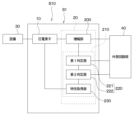
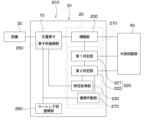
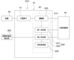
- FIG. 1 is a block diagram of an equipment state monitoring system according to a first embodiment.
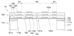
- FIG. 2 is a cross-sectional view of a piezoelectric element.
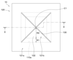
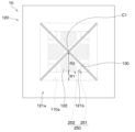
- FIG. 2 is a plan view of a piezoelectric element.
- FIG. 2 is a cross-sectional view of a piezoelectric device.
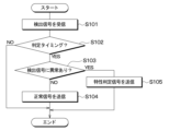
- 11 is a flowchart executed by a first determination unit.
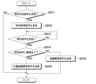
- 11 is a flowchart executed by a second determination unit.
- FIG. 11 is a block diagram of an equipment state monitoring system according to a modified example of the first embodiment.
- FIG. 11 is a block diagram of an equipment state monitoring system according to a second embodiment.
- FIG. 2 is a plan view of a piezoelectric element.
- FIG. 2 is a cross-sectional view of a piezoelectric device.
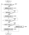
- FIG. 11 is a flowchart executed by a second determination unit.
- FIG. 11 is a cross-sectional view of a piezoelectric device according to a modified example of the second embodiment.
- FIG. 13 is a block diagram of an equipment state monitoring system according to a third embodiment.
- 11 is a flowchart executed by a second determination unit.
- the equipment status monitoring system of this embodiment is preferably provided in equipment that manufactures a specified product and used to detect abnormalities in the equipment.
- the equipment status monitoring system of this embodiment is provided in processing equipment having cutting tools and used to detect abnormalities such as wear and breakage of the cutting tools.
- the equipment to be judged can be changed as appropriate and may be a conveying facility, etc.
- the equipment status monitoring system S1 is configured to include a piezoelectric element 10 and a circuit section 20 having a control section 210.
- the piezoelectric element 10 and the circuit section 20 are arranged together in a casing 300 described below, and constitute an integrated piezoelectric device S10.
- the piezoelectric element 10 corresponds to the sensor element.
- the piezoelectric device S10 (i.e., the piezoelectric element 10) is provided in the equipment 30 and outputs a detection signal corresponding to the sound pressure generated in the equipment 30.
- the equipment 30 in this embodiment is a processing equipment having a cutting tool as described above.
- the piezoelectric element 10 of this embodiment will be described below with reference to Figures 2 and 3.
- the piezoelectric element 10 includes a support 110 and a vibration portion 120, and has a rectangular planar shape.
- the support 110 includes a support substrate 111 having one surface 111a and the other surface 111b, and an insulating film 112 formed on the one surface 111a of the support substrate 111.
- the support substrate 111 is made of, for example, a silicon substrate, and the insulating film 112 is made of, for example, an oxide film.
- the vibration part 120 is disposed on the support 110.
- a recess 110a is formed in the support 110 to allow the inner edge side of the vibration part 120 to float. Therefore, the vibration part 120 has a configuration including a support region 121a disposed on the support 110, and a floating region 121b that is connected to the support region 121a and floats above the recess 110a.
- the opening end of the recess 110a on the vibration part 120 side in this embodiment has a planar rectangular shape. Therefore, the entire floating region 121b has a planar rectangular shape.
- slits 130 are formed that penetrate the floating region 121b in the thickness direction.
- the slits 130 are formed so as to divide the floating region 121b into four. More specifically, two slits 130 are formed so as to pass through the center C1 of the floating region 121b and extend toward the opposing corners of the floating region 121b.
- the slits 130 are formed so as to extend from each corner of the floating region 121b, which is rectangular in plan view, toward the center C1, and each slit 130 intersects at the center C1.
- the floating region 121b is separated into four vibration regions 122 that are approximately triangular in plan view.
- the interval between each vibration region 122 i.e., the width of the slits 130
- the interval between each vibration region 122 is about 1 ⁇ m.
- Each vibration region 122 is a cantilever with the end on the support region 121a side as a fixed end and the tip end on the opposite side to the support region 121a as a free end.
- the surface of the vibration region 122 opposite the support 110 is referred to as one surface 122a of the vibration region 122, and the surface of the vibration region 122 on the support 110 side is referred to as the other surface 122b of the vibration region 122.
- the vibration section 120 is configured to have a piezoelectric film 140 and an electrode film 150 connected to the piezoelectric film 140.
- the piezoelectric film 140 has a lower piezoelectric film 141 and an upper piezoelectric film 142 laminated on the lower piezoelectric film 141.
- the lower piezoelectric film 141 and the upper piezoelectric film 142 are configured using lead-free piezoelectric ceramics such as scandium aluminum nitride (ScAlN) and aluminum nitride (AlN).
- the electrode film 150 is formed at a predetermined location in the vibration region 122 so as to be connected to the piezoelectric film 140, and is made of molybdenum, copper, platinum, titanium, or the like.
- the electrode film 150 includes a lower electrode film 151 formed below the lower piezoelectric film 141, an intermediate electrode film 152 formed between the lower piezoelectric film 141 and the upper piezoelectric film 142, and an upper electrode film 153 formed above the upper piezoelectric film 142.
- the lower electrode film 151 and the intermediate electrode film 152 are arranged to face each other with the lower piezoelectric film 141 in between.
- the intermediate electrode film 152 and the upper electrode film 153 are arranged to face each other with the upper piezoelectric film 142 in between.
- the lower electrode film 151, the intermediate electrode film 152, and the upper electrode film 153 have the same shape in the normal direction to one surface 122a of the vibration region 122 (hereinafter, simply referred to as the normal direction).
- the normal direction to one surface 122a of the vibration region 122 in other words, when viewed from the normal direction to one surface 122a of the vibration region 122.
- the vibration region 122 When the vibration region 122 is supported in a cantilever manner as described above, the stress generated when the vibration region 122 (i.e., the piezoelectric film 140) vibrates tends to be greater on the fixed end side where the vibration region 122 is supported than on the free end side. For this reason, the vibration region 122 is divided into a first region R1 where the stress tends to be greater, and a second region R2 where the stress tends to be smaller.
- an electrode film 150 is formed in each of the first region R1 and the second region R2.
- the electrode film 150 formed in the first region R1 and the electrode film 150 formed in the second region R2 are insulated from each other.
- the electrode film 150 formed in the first region R1 is connected to an electrode portion (not shown) via wiring or the like formed in the support region 121a, although this is not shown in the figure.
- the lower electrode film 151, intermediate electrode film 152, and upper electrode film 153 in each vibration region 122 are connected to the electrode portion so that the change in charge in the first region R1 of each vibration region 122 is output as a single detection signal.
- the lower electrode film 151, intermediate electrode film 152, and upper electrode film 153 formed in the second region R2 are not electrically connected to the respective electrode portions and are in a floating state. Therefore, the lower electrode film 151, intermediate electrode film 152, and upper electrode film 153 formed in the second region R2 are not necessarily required, but in this embodiment, they are provided to protect the portions of the lower piezoelectric film 141 and upper piezoelectric film 142 located in the second region R2.
- the lower electrode film 151, intermediate electrode film 152, and upper electrode film 153 formed in the first region R1 and the second region R2 are each formed so as not to reach the slit 130.
- the lower electrode film 151, intermediate electrode film 152, and upper electrode film 153 are formed so as to terminate more inward than the side surface exposed from the slit 130 in the vibration region 122.
- the lower electrode film 151, intermediate electrode film 152, and upper electrode film 153 are disposed more inward than the slit 130 in the normal direction to one surface 122a of the vibration region 122.
- the vibration section 120 of this embodiment has a base film 160 on which the lower piezoelectric film 141 and the lower electrode film 151 are disposed.
- the piezoelectric film 140 and the electrode film 150 are disposed on the support 110 via the base film 160.
- the other surface 122b of each vibration region 122 is formed of the base film 160.
- the base film 160 is not necessarily required, but is provided to facilitate crystal growth when forming the lower piezoelectric film 141 and the like.
- the base film 160 is made of aluminum nitride or the like.
- the piezoelectric film 140 has a thickness of about 1 ⁇ m, and the base film 160 has a thickness of about several tens of nm. In other words, the base film 160 is made extremely thin compared to the piezoelectric film 140.
- each vibration region 122 vibrates.
- tensile stress is generated in the lower piezoelectric film 141 and compressive stress is generated in the upper piezoelectric film 142, and the charges of the lower piezoelectric film 141 and the upper piezoelectric film 142 change. Therefore, the sound pressure applied to the vibration region 122 is detected based on the charges of the lower piezoelectric film 141 and the upper piezoelectric film 142.
- each vibration region 122 is divided into a first region R1 where stress is likely to be large and a second region R2 where stress is likely to be small.
- the charge generated in the lower layer piezoelectric film 141 and upper layer piezoelectric film 142 located in the first region R1 is extracted from the lower layer electrode film 151, upper layer electrode film 153, and intermediate electrode film 152 arranged in the first region R1. This makes it possible to suppress the influence of noise from becoming too large.
- the circuit section 20 includes an amplifier section 200 and a control section 210.
- the piezoelectric element 10 and the circuit section 20 are both housed in a casing 300 to form the piezoelectric device S10.
- the casing 300 has a printed circuit board 310 on which the piezoelectric element 10 and the circuit section 20 are mounted, and a lid section 320 that is fixed to the printed circuit board 310 so as to house the piezoelectric element 10 and the circuit section 20.
- the printed circuit board 310 can also be considered a mounted member.
- the printed circuit board 310 is configured with wiring sections and through-hole electrodes, etc., which are not shown, appropriately formed, and also has electronic components, such as capacitors, etc., mounted thereon as necessary (not shown).
- the piezoelectric element 10 is mounted on one surface 310a of the printed circuit board 310, with the other surface 111b of the support substrate 111 being mounted via a bonding member 330, such as an adhesive.
- a through hole 311 is formed in a portion of the printed circuit board 310 facing the vibration region 122.
- the circuit section 20 is mounted on one surface 310a of the printed circuit board 310 via a bonding member 340 made of a conductive material.
- the piezoelectric element 10 and the circuit section 20 are electrically connected via a bonding wire 301.
- the lid section 320 is made of metal, plastic, resin, etc., and is fixed to the printed circuit board 310 via a bonding member such as an adhesive (not shown) so as to accommodate the piezoelectric element 10 and the circuit section 20.
- Such a piezoelectric device S10 is arranged so that sound pressure generated from the equipment 30 is applied to the vibration region 122 through the through hole 311.
- the piezoelectric element 10 then transmits a detection signal to the circuit section 20 according to the sound pressure (i.e., pressure) introduced from the through hole 311.
- the circuit section 20 is configured to include the amplifier section 200 and the control section 210.
- the amplifier unit 200 When the amplifier unit 200 receives a detection signal from the piezoelectric element 10, it amplifies the detection signal and transmits it to the control unit 210 and the external circuit unit 40.
- the control unit 210 is composed of a microcomputer equipped with a CPU and a memory unit composed of non-transient physical storage media such as ROM, RAM, flash memory, and HDD, and has a judgment unit 220 and a characteristic acquisition unit 230.
- CPU stands for Central Processing Unit
- ROM Read Only Memory
- RAM Random Access Memory
- HDD Hard Disk Drive.
- Storage media such as ROM are non-transient physical storage media.
- the judgment unit 220 of this embodiment has a first judgment unit 221 and a second judgment unit 222.
- the first judgment unit 221 performs a first abnormality judgment by comparing the amplified detection signal with a predetermined first threshold range. Specifically, the first judgment unit 221 judges that the detection signal is normal if the detection signal is within the first threshold range, and judges that the detection signal is abnormal if the detection signal is outside the first threshold range. For example, when detecting the state of a cutting tool in the equipment 30, the sound pressure introduced from the through hole 311 increases as the wear of the cutting tool increases. Therefore, the first judgment unit 221 judges that the detection signal is abnormal if the detection signal increases and falls outside the first threshold range.
- the first judgment unit 221 judges that the detection signal is abnormal, it transmits a characteristic judgment signal to the second judgment unit 222. Furthermore, when the first judgment unit 221 judges that the detection signal is within the first threshold range, the equipment 30 is normal, and therefore transmits a normal signal to the external circuit unit 40.
- the first threshold range is a range for understanding the condition of the equipment, and is set appropriately based on the material and shape of the cutting tool, for example, so that wear on the cutting tool can be detected.
- the second judgment unit 222 When the second judgment unit 222 receives a characteristic judgment signal from the first judgment unit 221, it transmits a characteristic acquisition signal to the characteristic acquisition unit 230. Then, when the second judgment unit 222 receives a characteristic signal from the characteristic acquisition unit 230 as described below, it performs a second abnormality judgment in which it compares the characteristic signal with a second threshold range. Specifically, if the characteristic signal is within the second threshold range, the second judgment unit 222 judges that the characteristic signal is normal, and if the characteristic signal is outside the second threshold range, it judges that the characteristic signal is abnormal.
- the second judgment unit 222 judges that the piezoelectric device S10 is normal and that the equipment 30 is abnormal, and if the characteristic signal is outside the second threshold range, it judges that the piezoelectric device S10 is abnormal and that the equipment 30 is normal.
- the second judgment unit 222 performs a self-diagnosis of the piezoelectric device S10. For example, in the piezoelectric element 10 described above, if a foreign object adheres to the vibration region 122 or if the vibration region 122 is damaged, the mass increases and the resonance frequency changes. Therefore, the second determination unit 222 determines that an abnormality exists when the characteristic signal based on the resonance frequency changes and falls outside the second threshold range.
- the second threshold range is a range for grasping the state of the piezoelectric device S10, and is set appropriately based on the sensitivity of the vibration region 122, etc.
- the second determination unit 222 determines that the piezoelectric device S10 is normal, it transmits an equipment abnormality signal indicating that the equipment 30 is abnormal to the external circuit unit 40. If the second determination unit 222 determines that the piezoelectric device S10 is abnormal, it transmits a piezoelectric device abnormality signal indicating that the piezoelectric device S10 is abnormal to the external circuit unit 40.
- the characteristic acquisition unit 230 is configured to include an RLC circuit having resistors, coils, capacitors, etc. Then, when the characteristic acquisition unit 230 receives a characteristic acquisition signal from the second determination unit 222, it transmits a characteristic signal indicating the characteristics of the piezoelectric element 10. In this embodiment, the characteristic acquisition unit 230 transmits a characteristic signal based on the resonance frequency of the vibration region 122 in the piezoelectric element 10 to the second determination unit 222. Note that, as described above, the characteristic signal based on the resonance frequency of the vibration region 122 changes when a foreign object adheres to the vibration region 122 or when the vibration region 122 is damaged, etc.
- the external circuit unit 40 performs a predetermined process according to the signal it receives.
- the external circuit unit 40 is connected to a display device that can be seen by an operator, and causes the display device to display the status of the equipment 30 and the piezoelectric device S10.
- the external circuit unit 40 when the external circuit unit 40 receives a normal signal from the first determination unit 221, it displays that the equipment 30 and the piezoelectric device S10 are normal. On the other hand, when the external circuit unit 40 receives an equipment abnormality signal from the second determination unit 222, it displays on the display device that an abnormality has occurred in the equipment 30. Furthermore, when the external circuit unit 40 receives a piezoelectric device abnormality signal from the second determination unit 222, it displays on the display device that an abnormality has occurred in the piezoelectric device S10.
- step S101 the first judgment unit 221 receives the amplified detection signal from the amplifier unit 200.
- step S102 the first judgment unit 221 judges whether it is judgment timing.
- the judgment timing is set to be when the equipment 30 starts or stops operating, or at predetermined intervals. However, the judgment timing of the first judgment unit 221 can be changed as appropriate. Then, if the first judgment unit 221 judges that it is not judgment timing (i.e., step S102: NO), it ends the process as it is.
- the first judgment unit 221 judges that it is judgment timing (i.e., step S102: YES), it performs a first abnormality judgment in which the detection signal is compared with the first threshold range in step S103. Then, if the first judgment unit 221 judges that the detection signal is within the first threshold range and there is no abnormality in the detection signal (i.e., step S103: NO), it transmits a normal signal to the external circuit unit 40 in step S104 and ends the process. On the other hand, if the first judgment unit 221 judges that the detection signal is outside the first threshold range and there is an abnormality in the detection signal (i.e., step S103: YES), it transmits a characteristic judgment signal to the second judgment unit 222 in step S105 and ends the process.
- step S201 the second determination unit 222 determines whether or not a characteristic determination signal has been received, and ends the process if it determines that a characteristic determination signal has not been received (i.e., step S201: NO). If the second determination unit 222 determines that a characteristic determination signal has been received (i.e., step S201: YES), it transmits a characteristic acquisition signal to the characteristic acquisition unit 230 in step S202. As a result, the characteristic acquisition unit 230 transmits a characteristic signal based on the resonance frequency of the vibration region 122 in the piezoelectric element 10 to the second determination unit 222. Note that, as described above, the characteristic signal based on the vibration region 122 changes if a foreign object adheres to the vibration region 122, if the vibration region 122 is damaged, etc.
- step S203 the second determination unit 222 determines whether or not a characteristic signal has been received, and if it determines that a characteristic signal has not been received (i.e., step S203: NO), it executes the process of step S203 again. In other words, the second determination unit 222 waits until a characteristic signal is received.
- step S204 determines that it has received a characteristic signal (i.e., step S203: YES)
- it performs a second abnormality determination in step S204 comparing the characteristic signal with the second threshold range. In other words, it performs a self-diagnosis of the piezoelectric device S10.
- step S204 determines that the characteristic signal is not within the second threshold range (i.e., step S204: YES)
- the characteristic signal is abnormal, so in step S205 it transmits a piezoelectric device abnormality signal indicating that the piezoelectric device S10 is abnormal to the external circuit unit 40.
- step S204 determines that the characteristic signal is within the second threshold range (i.e., step S204: NO)
- a second abnormality determination is made to determine whether or not the characteristic signal based on the characteristics of the piezoelectric device S10 is within the second threshold range.
- a characteristic operation unit 240 may be provided, which is composed of a sound source that generates sound pressure and is connected to the characteristic acquisition unit 230.
- the characteristic operation unit 240 is configured to be capable of generating sound pressures of a plurality of different frequencies so as to correspond to the resonance frequency in the vibration region 122.
- the characteristic acquisition unit 230 may derive a characteristic signal based on the resonance frequency of the piezoelectric element 10 based on a detection signal generated by operating the characteristic operation unit 240, and transmit the derived characteristic signal to the second determination unit 222. In this way, the resonance frequency as the characteristic signal may be mechanically acquired.
- Second Embodiment A second embodiment will be described. This embodiment is different from the first embodiment in that a return operation is performed. As the rest of the configuration is the same as the first embodiment, a description thereof will be omitted here.
- the equipment status monitoring system S1 further includes an element return section 250, a casing return section 260, and a return operation section 270.
- the piezoelectric element 10 of this embodiment has a temperature detection element 251 that outputs a temperature detection signal according to temperature and a heating element 252 that generates heat when current is applied, arranged as an element return section 250 in each vibration region 122.
- the temperature detection element 251 and the heating element 252 are formed in the second region R2 of each vibration region 122. More specifically, in this embodiment, the intermediate electrode film 152 is not formed in the second region R2.
- the temperature detection element 251 and the heating element 252 are formed in a portion located between the lower piezoelectric film 141 and the upper piezoelectric film 142. In other words, the temperature detection element 251 and the heating element 252 are formed in the portion where the intermediate electrode film 152 in the first embodiment was formed.
- the temperature detection element 251 is, for example, configured using a temperature-sensitive resistor whose resistance value changes depending on the temperature, and the heating element 252 is, for example, configured using a heating resistor that generates heat when electricity is passed through it.
- the temperature detection element 251 and the heating element 252 are, for example, configured using platinum.
- the casing 300 is also provided with a temperature detection unit 261, a heat generation unit 262, and a vibration unit 263 as a casing return unit 260.
- the heat generating section 262 is composed of, for example, a resistance heater.
- the temperature detecting section 261 is composed of a thermistor.
- the vibration section 263 is composed of a piezoelectric element. Although not shown in the figure, the temperature detecting section 261, the heat generating section 262, and the vibration section 263 are each electrically connected to the circuit section 20 via wires or the like.
- FIG. 10 shows an example in which the vibration unit 263 is disposed inside the casing 300, and the temperature detection unit 261 and the heat generation unit 262 are disposed outside the casing 300.
- the locations of these are not particularly limited, and the vibration unit 263 may be disposed outside the casing 300, and the temperature detection unit 261 and the heat generation unit 262 may be disposed inside the casing 300.
- the return operation unit 270 is connected to the element return unit 250 and the casing return unit 260, and when it receives a return start signal from the second determination unit 222 as described below, it activates the element return unit 250 and the casing return unit 260.
- the return operation unit 270 controls the temperature detection element 251 and the heating element 252 of the piezoelectric element 10 so that the temperature of the temperature detection element 251 (i.e., the piezoelectric element 10) becomes a predetermined temperature.
- the return operation unit 270 applies a predetermined voltage to the piezoelectric element 10 to vibrate the vibration region 122.
- the target object for the element return unit 250 is the piezoelectric element 10.
- the return operation unit 270 controls the temperature detection unit 261 and the heating unit 262 arranged in the casing 300 so that the temperature of the temperature detection unit 261 (i.e., the casing 300) becomes a predetermined temperature. As a result, if foreign matter such as water is attached to the casing 300, the foreign matter can be evaporated. In addition, the return operation unit 270 applies a predetermined voltage to the vibration unit 263 arranged in the casing 300 to vibrate the casing 300. As a result, if foreign matter such as water is attached to the casing 300, the foreign matter can be brushed off.
- the target object for the casing return unit is the casing 300.
- the second determination unit 222 When the second determination unit 222 receives the characteristic determination signal, it transmits a recovery start signal to the recovery operation unit 270. This causes the recovery operation unit 270 to perform the above-mentioned operation. The second determination unit 222 then performs a second abnormality determination by comparing the characteristic signal after recovery processing with the second threshold range.
- step S210 When the second determination unit 222 determines in step S201 that it has received a characteristic determination signal (i.e., S201: YES), in step S210 it sends a return start signal to the return operation unit 270. This causes the return operation unit 270 to operate the element return unit 250 and the casing return unit 260, and performs an operation to remove the foreign matter if any foreign matter is attached.
- a characteristic determination signal i.e., S201: YES
- step S211 it is determined whether or not a predetermined return time has elapsed. In other words, it is determined whether or not the return operation has been completed. If it is determined that the return time has not elapsed (i.e., step S211: NO), the process of step S211 is performed again. In other words, it waits until the return time has elapsed.
- the second determination unit 222 determines that the return time has elapsed (i.e., step S211: YES), it performs the processes of steps S202 to S206. In this case, in the process of step S204, the characteristic signal after the return operation is performed is compared with the second threshold value. In other words, the characteristic signal in which the adhesion of foreign matter or the like is suppressed is compared with the second threshold value. This improves the accuracy of abnormality determination for the characteristic signal.
- a second abnormality determination is made to determine whether the characteristic signal based on the characteristics of the piezoelectric device S10 is within the second threshold range. Therefore, it is possible to obtain the same effect as the first embodiment described above.
- the piezoelectric device S10 is reset before the second abnormality determination is made. This makes it possible to eliminate abnormalities caused by foreign matter adhering to the piezoelectric device S10, and also makes it possible to prevent erroneous determination that the piezoelectric device S10 is abnormal.
- the second determination unit 222 may transmit an adjustment signal to the return operation unit 270 to control the temperature detection element 251 and the heating element 252 so that the vibration region 122 is kept constant at a predetermined temperature.
- the second determination unit 222 may transmit an adjustment signal to the return operation unit 270 to control the temperature detection unit 261 and the heating unit 262 so that the casing 300 is kept constant at a predetermined temperature.
- the detection signal from the piezoelectric element 10 becomes a signal in a state where the predetermined temperature is maintained. Therefore, it is possible to suppress variation in detection accuracy.
- the configurations of the element return section 250 and the casing return section 260 can be changed as appropriate.
- the casing return section 260 may be configured with an air blower 264 that applies a predetermined wind pressure to the through hole 311 of the casing 300, as shown in FIG. 12.
- an air blower that applies wind pressure to the piezoelectric element 10 may be disposed in the casing 300.
- the element return section 250 may be configured to have only the heating element 252 of the temperature detection element 251 and the heating element 252
- the casing return section 260 may be configured to have only the heating section 262 of the temperature detection section 261 and the heating section 262.
- the return portion includes the element return portion 250 and the casing return portion 260, but the configuration may include only one of the element return portion 250 and the casing return portion 260.
- Third Embodiment A third embodiment will be described. This embodiment is different from the first embodiment in that it detects the surrounding conditions of the equipment 30. As the rest is similar to the first embodiment, the description will be omitted here.
- the equipment status monitoring system S1 of this embodiment includes an ambient temperature detection unit 280 as an ambient detection unit.
- the ambient temperature detection unit 280 is composed of a thermistor or the like, and is connected to the second determination unit 222.
- the ambient temperature detection unit 280 is disposed, for example, in the vicinity of the equipment 30, and transmits a status signal corresponding to the ambient condition (i.e., temperature) of the equipment 30 to the second determination unit 222.
- the second judgment unit 222 When the second judgment unit 222 receives the characteristic judgment signal, it performs a third abnormality judgment by comparing the status signal with a third threshold range. Specifically, if the status signal is within the third threshold range, the second judgment unit 222 judges that the status signal is normal, and if the status signal is outside the third threshold range, it judges that the status signal is abnormal. More specifically, if the status signal is within the third threshold range, the second judgment unit 222 judges that the surrounding conditions of the equipment 30 are normal, and if the status signal is outside the third threshold range, it judges that the surrounding conditions are abnormal. Then, if the second judgment unit 222 judges that the status signal is outside the third threshold range, the surrounding conditions are abnormal, and so it transmits a surrounding abnormality signal to the external circuit unit 40.
- an abnormality in the surrounding conditions of the equipment 30 refers to an abnormally high temperature in the equipment 30 or in devices around the equipment 30.
- the third threshold range is a range for grasping the surrounding conditions of the equipment 30, and is set based on the possible range of temperatures around the equipment 30 during normal use, for example.
- the external circuit unit 40 When the external circuit unit 40 receives an ambient abnormality signal from the second judgment unit 222, it causes the display device to display a message indicating that the ambient temperature of the equipment 30 is abnormal.
- the second determination unit 222 When the second determination unit 222 receives the characteristic determination signal in step S201, it performs a third abnormality determination in step S220 by comparing the status signal with a third threshold range.
- step S220 determines that the status signal is not within the third threshold range (i.e., step S220: YES)
- step S220 determines that the surrounding conditions of the equipment 30 are abnormal, and therefore, in step S221, a surrounding abnormality signal is sent to the external circuit unit 40.
- step S200 determines that the status signal is within the third value range (i.e., step S200: NO)
- the surrounding conditions of the equipment 30 are normal, and therefore, the processing of steps S202 to S206 is performed.
- a second abnormality determination is made to determine whether the characteristic signal based on the characteristics of the piezoelectric device S10 is within the second threshold range. Therefore, it is possible to obtain the same effect as the first embodiment described above.
- the ambient temperature detection unit 280 is provided as the ambient detection unit.
- the configuration of the ambient detection unit can be appropriately changed, and may be, for example, configured with a humidity detection unit that detects the ambient humidity, a vibration detection unit that detects the ambient vibration, a sound detection unit that detects the ambient sound, and an illuminance detection unit that detects the ambient illuminance.
- the ambient temperature detection unit 280 as the ambient detection unit is arranged around the equipment 30.
- the ambient detection unit may also be arranged inside the piezoelectric device S10. Note that the piezoelectric device S10 outputs a detection signal according to the state of the equipment 30, and is arranged around the equipment 30. For this reason, even if the ambient temperature detection unit 280 is arranged inside the piezoelectric device S10, it can be said that the ambient temperature detection unit 280 transmits a state signal according to the state around the equipment 30.
- the third abnormality judgment was performed before the second abnormality judgment was performed, but the third abnormality judgment may be performed after the second abnormality judgment.
- control unit 210 is described as having a first determination unit 221 and a second determination unit 222, but the first determination unit 221 and the second determination unit 222 may be integrated.
- control unit 210 is mounted on the circuit unit 20, but the control unit 210 may be provided in, for example, the external circuit unit 40. Furthermore, the circuit unit 20 may be disposed outside the casing 300.
- the sensor element may be composed of an acceleration detection element, an angular velocity detection element, a temperature detection element, a light detection element, a humidity detection element, or the like.
- a plurality of sensor elements may be provided so that detection signals corresponding to different physical quantities are transmitted.
- a piezoelectric element and a humidity detection element may be provided, and the above determination may be made by combining the respective detection signals. This can further reduce erroneous determinations.
- control unit and the method described in the present disclosure may be realized by a dedicated computer provided by configuring a processor and memory programmed to execute one or more functions embodied in a computer program.
- control unit and the method described in the present disclosure may be realized by a dedicated computer provided by configuring a processor with one or more dedicated hardware logic circuits.
- control unit and the method described in the present disclosure may be realized by one or more dedicated computers configured by combining a processor and memory programmed to execute one or more functions with a processor configured with one or more hardware logic circuits.
- the computer program may be stored in a computer-readable non-transient tangible recording medium as instructions executed by the computer.
- An equipment status monitoring system comprising: A sensor device (S10) having a sensor element (10) that transmits a detection signal corresponding to a state of a facility (30); A control unit (210) that performs a predetermined process based on the detection signal, The control unit performs a first abnormality judgment by comparing the detection signal with a first threshold range for grasping the status of the equipment, and determining that the detection signal is abnormal when the detection signal is outside the first threshold range, and a second abnormality judgment by comparing a characteristic signal indicating a characteristic of the sensor device with a second threshold range for grasping the status of the sensor device when the first abnormality judgment determines that the detection signal is abnormal, and determining that the characteristic signal is abnormal and that an abnormality has occurred in the sensor device when the characteristic signal is outside the second threshold range.
- a return portion (250, 260) is provided in the sensor device, An equipment status monitoring system as described in a first aspect, wherein when the control unit determines that an abnormality exists in the first abnormality judgment, the control unit controls the return unit to perform a return operation to return the state of the sensor device before making the second abnormality judgment, and makes the second abnormality judgment after the return operation is completed.
- the sensor device includes the sensor element and a casing (300) that houses the sensor element, The facility status monitoring system according to the first or second aspect, wherein the resetting unit is a sensor element resetting unit (250) provided in the sensor element for resetting the state of the sensor element.
- the sensor device includes the sensor element and a casing (300) that houses the sensor element,
- the equipment status monitoring system according to the first or second aspect wherein the restoring unit is a casing restoring unit (260) provided in the casing for restoring the state of the casing.
- the recovery unit generates heat to heat the target object.
- the return unit vibrates the target object.
- the return unit applies wind pressure to the target object.
- a surrounding detection unit (270) that transmits a status signal according to the surroundings of the equipment An equipment status monitoring system according to any one of the first to seventh aspects, wherein when the first abnormality judgment determines that an abnormality exists, the control unit performs a third abnormality judgment in which the status signal is compared with a third threshold range for grasping the surrounding condition of the equipment, and determines that the surrounding condition of the equipment is abnormal when the status signal is outside the third threshold range.
- the facility status monitoring system according to any one of the first to eighth aspects, wherein a plurality of the sensor elements are provided, and each of the sensor elements transmits the detection signals corresponding to different physical quantities.
Landscapes
- Engineering & Computer Science (AREA)
- Physics & Mathematics (AREA)
- General Physics & Mathematics (AREA)
- Automation & Control Theory (AREA)
- Manufacturing & Machinery (AREA)
- Measurement Of Mechanical Vibrations Or Ultrasonic Waves (AREA)
- Testing Of Devices, Machine Parts, Or Other Structures Thereof (AREA)
- Mechanical Engineering (AREA)
- Testing Or Calibration Of Command Recording Devices (AREA)
Priority Applications (3)
| Application Number | Priority Date | Filing Date | Title |
|---|---|---|---|
| CN202380079379.7A CN120303539A (zh) | 2022-11-17 | 2023-11-15 | 设备状态监视系统 |
| EP23891612.6A EP4621366A4 (en) | 2022-11-17 | 2023-11-15 | EQUIPMENT CONDITION MONITORING SYSTEM |
| US19/209,341 US20250269482A1 (en) | 2022-11-17 | 2025-05-15 | Equipment state monitoring system |
Applications Claiming Priority (2)
| Application Number | Priority Date | Filing Date | Title |
|---|---|---|---|
| JP2022-184237 | 2022-11-17 | ||
| JP2022184237A JP7845151B2 (ja) | 2022-11-17 | 2022-11-17 | 設備状態監視システム |
Related Child Applications (1)
| Application Number | Title | Priority Date | Filing Date |
|---|---|---|---|
| US19/209,341 Continuation US20250269482A1 (en) | 2022-11-17 | 2025-05-15 | Equipment state monitoring system |
Publications (1)
| Publication Number | Publication Date |
|---|---|
| WO2024106465A1 true WO2024106465A1 (ja) | 2024-05-23 |
Family
ID=91084506
Family Applications (1)
| Application Number | Title | Priority Date | Filing Date |
|---|---|---|---|
| PCT/JP2023/041090 Ceased WO2024106465A1 (ja) | 2022-11-17 | 2023-11-15 | 設備状態監視システム |
Country Status (6)
| Country | Link |
|---|---|
| US (1) | US20250269482A1 (enExample) |
| EP (1) | EP4621366A4 (enExample) |
| JP (1) | JP7845151B2 (enExample) |
| CN (1) | CN120303539A (enExample) |
| TW (1) | TWI871042B (enExample) |
| WO (1) | WO2024106465A1 (enExample) |
Cited By (1)
| Publication number | Priority date | Publication date | Assignee | Title |
|---|---|---|---|---|
| WO2026100243A1 (ja) * | 2024-11-05 | 2026-05-15 | 国立大学法人東北大学 | 電界センサ |
Citations (6)
| Publication number | Priority date | Publication date | Assignee | Title |
|---|---|---|---|---|
| JP2001097032A (ja) * | 1999-09-30 | 2001-04-10 | Denso Corp | 車両用空調装置 |
| JP2011038673A (ja) * | 2009-08-07 | 2011-02-24 | Shimizu Corp | 脱臭空調システム |
| JP2014238334A (ja) * | 2013-06-07 | 2014-12-18 | 能美防災株式会社 | 構造物劣化診断システム |
| JP2016029390A (ja) * | 2015-10-28 | 2016-03-03 | 株式会社エヌ・ティ・ティ・データ | 異常検出装置、異常検出方法、異常検出プログラム |
| JP2021012129A (ja) * | 2019-07-08 | 2021-02-04 | 三菱重工業株式会社 | 軸振動監視システム、回転機械 |
| JP7156558B2 (ja) | 2019-12-25 | 2022-10-19 | 株式会社デンソー | 圧電素子、圧電装置、および圧電素子の製造方法 |
Family Cites Families (12)
| Publication number | Priority date | Publication date | Assignee | Title |
|---|---|---|---|---|
| JPS59128414A (ja) * | 1983-01-14 | 1984-07-24 | Sumitomo Heavy Ind Ltd | 舶用機器センサの故障診断装置 |
| US6510397B1 (en) * | 1999-03-13 | 2003-01-21 | Textron Systems Corporation | Method and apparatus for self-diagnosis of a sensor |
| JP2005172685A (ja) * | 2003-12-12 | 2005-06-30 | Nsk Ltd | 機械設備の監視システム |
| EP2037251A4 (en) * | 2006-07-04 | 2012-10-24 | Ngk Insulators Ltd | PIEZOELECTRIC / ELECTROSTRICTIVE FILM-TYPE SENSOR |
| JP2009236596A (ja) * | 2008-03-26 | 2009-10-15 | Jfe Steel Corp | 振動センサ及び振動センサの状態判別方法 |
| GB0813014D0 (en) * | 2008-07-16 | 2008-08-20 | Groveley Detection Ltd | Detector and methods of detecting |
| JP5489968B2 (ja) * | 2010-12-09 | 2014-05-14 | 日本発條株式会社 | 圧電素子のクラック検出方法及びその装置 |
| JP5832814B2 (ja) * | 2011-08-11 | 2015-12-16 | 株式会社エヌ・ティ・ティ・データ | 異常検出装置、異常検出方法、異常検出プログラム |
| GB2515718B (en) * | 2013-02-14 | 2015-09-09 | Roger Thomas Hurrey | Piezoelectric Sensor Compression Assembly, Self-Test and Background Sensitivity |
| JP6587941B2 (ja) * | 2016-01-14 | 2019-10-09 | 株式会社デンソーテン | 入力装置、表示装置、および、入力装置の振動状態検出方法 |
| CN107491374B (zh) * | 2017-08-11 | 2020-06-05 | 安徽容知日新科技股份有限公司 | 一种设备停机状态的判断方法及计算设备 |
| CN111522804A (zh) * | 2020-04-15 | 2020-08-11 | 国网江苏省电力有限公司 | 一种变压器设备状态监测异常数据清洗方法 |
-
2022
- 2022-11-17 JP JP2022184237A patent/JP7845151B2/ja active Active
-
2023
- 2023-10-11 TW TW112138664A patent/TWI871042B/zh active
- 2023-11-15 EP EP23891612.6A patent/EP4621366A4/en active Pending
- 2023-11-15 CN CN202380079379.7A patent/CN120303539A/zh active Pending
- 2023-11-15 WO PCT/JP2023/041090 patent/WO2024106465A1/ja not_active Ceased
-
2025
- 2025-05-15 US US19/209,341 patent/US20250269482A1/en active Pending
Patent Citations (6)
| Publication number | Priority date | Publication date | Assignee | Title |
|---|---|---|---|---|
| JP2001097032A (ja) * | 1999-09-30 | 2001-04-10 | Denso Corp | 車両用空調装置 |
| JP2011038673A (ja) * | 2009-08-07 | 2011-02-24 | Shimizu Corp | 脱臭空調システム |
| JP2014238334A (ja) * | 2013-06-07 | 2014-12-18 | 能美防災株式会社 | 構造物劣化診断システム |
| JP2016029390A (ja) * | 2015-10-28 | 2016-03-03 | 株式会社エヌ・ティ・ティ・データ | 異常検出装置、異常検出方法、異常検出プログラム |
| JP2021012129A (ja) * | 2019-07-08 | 2021-02-04 | 三菱重工業株式会社 | 軸振動監視システム、回転機械 |
| JP7156558B2 (ja) | 2019-12-25 | 2022-10-19 | 株式会社デンソー | 圧電素子、圧電装置、および圧電素子の製造方法 |
Non-Patent Citations (1)
| Title |
|---|
| See also references of EP4621366A1 |
Cited By (1)
| Publication number | Priority date | Publication date | Assignee | Title |
|---|---|---|---|---|
| WO2026100243A1 (ja) * | 2024-11-05 | 2026-05-15 | 国立大学法人東北大学 | 電界センサ |
Also Published As
| Publication number | Publication date |
|---|---|
| TW202434867A (zh) | 2024-09-01 |
| CN120303539A (zh) | 2025-07-11 |
| US20250269482A1 (en) | 2025-08-28 |
| JP7845151B2 (ja) | 2026-04-14 |
| EP4621366A1 (en) | 2025-09-24 |
| JP2024073168A (ja) | 2024-05-29 |
| TWI871042B (zh) | 2025-01-21 |
| EP4621366A4 (en) | 2026-04-01 |
Similar Documents
| Publication | Publication Date | Title |
|---|---|---|
| US7325457B2 (en) | Sensor and sensor module | |
| US20250269482A1 (en) | Equipment state monitoring system | |
| JP5568586B2 (ja) | 電子装置、故障判定方法、寿命推定方法 | |
| KR20090087847A (ko) | 반도체 감왜 센서 | |
| US20250066186A1 (en) | Environmental sensor and method for operating an environmental sensor | |
| US20130305804A1 (en) | Microelectromechanical component and method for testing a microelectromechanical component | |
| CN110118612A (zh) | 检测超声波转换器的振动元件的温度的方法及装置 | |
| JP2003023349A (ja) | 半導体バッファ能力調整方法、半導体バッファ能力調整システム、及び半導体装置 | |
| JPH02503171A (ja) | 一体型のセンサを有するインテリジェントインサート | |
| CN112114009B (zh) | 一种具备自我诊断功能的湿度传感器芯片及湿度传感器芯片的自我诊断方法 | |
| JP5070813B2 (ja) | 電子部品およびその製造方法 | |
| US10837845B2 (en) | Detection of strain direction in an integrated circuit | |
| JP2005114440A (ja) | 故障診断可能な静電容量検出型加速度センサ | |
| US20230341282A1 (en) | Sensor element and sensor device having same | |
| US6796176B2 (en) | Inertial sensor with an integrated temperature probe | |
| KR200144765Y1 (ko) | 진동 및 온도 온라인 측정시스템 | |
| JP2002162411A (ja) | 半導体加速度センサおよび半導体加速度センサの検査方法 | |
| US12470875B2 (en) | Piezoelectric element, piezoelectric device, and manufacturing method of piezoelectric element | |
| JP3191404B2 (ja) | 圧電振動子の温度検知方法 | |
| JPWO2012017532A1 (ja) | 半導体センサ | |
| JP2005207974A (ja) | 角速度および加速度検出用複合センサ | |
| JP5816340B2 (ja) | 電子装置、故障判定方法、寿命推定方法、プログラム | |
| JP5052443B2 (ja) | 静電容量型センサの実装構造 | |
| JP2007278761A (ja) | タイヤ空気圧検出装置 | |
| JPH11233793A (ja) | 半導体装置の製造方法 |
Legal Events
| Date | Code | Title | Description |
|---|---|---|---|
| 121 | Ep: the epo has been informed by wipo that ep was designated in this application |
Ref document number: 23891612 Country of ref document: EP Kind code of ref document: A1 |
|
| WWE | Wipo information: entry into national phase |
Ref document number: 202380079379.7 Country of ref document: CN |
|
| WWE | Wipo information: entry into national phase |
Ref document number: 2023891612 Country of ref document: EP |
|
| NENP | Non-entry into the national phase |
Ref country code: DE |
|
| ENP | Entry into the national phase |
Ref document number: 2023891612 Country of ref document: EP Effective date: 20250617 |
|
| WWP | Wipo information: published in national office |
Ref document number: 202380079379.7 Country of ref document: CN |
|
| WWP | Wipo information: published in national office |
Ref document number: 2023891612 Country of ref document: EP |