WO2024101415A1 - 固定治具 - Google Patents
固定治具 Download PDFInfo
- Publication number
- WO2024101415A1 WO2024101415A1 PCT/JP2023/040359 JP2023040359W WO2024101415A1 WO 2024101415 A1 WO2024101415 A1 WO 2024101415A1 JP 2023040359 W JP2023040359 W JP 2023040359W WO 2024101415 A1 WO2024101415 A1 WO 2024101415A1
- Authority
- WO
- WIPO (PCT)
- Prior art keywords
- discharge port
- bag
- frame
- frame body
- bottle needle
- Prior art date
- Legal status (The legal status is an assumption and is not a legal conclusion. Google has not performed a legal analysis and makes no representation as to the accuracy of the status listed.)
- Ceased
Links
Images




Classifications
-
- A—HUMAN NECESSITIES
- A61—MEDICAL OR VETERINARY SCIENCE; HYGIENE
- A61J—CONTAINERS SPECIALLY ADAPTED FOR MEDICAL OR PHARMACEUTICAL PURPOSES; DEVICES OR METHODS SPECIALLY ADAPTED FOR BRINGING PHARMACEUTICAL PRODUCTS INTO PARTICULAR PHYSICAL OR ADMINISTERING FORMS; DEVICES FOR ADMINISTERING FOOD OR MEDICINES ORALLY; BABY COMFORTERS; DEVICES FOR RECEIVING SPITTLE
- A61J1/00—Containers specially adapted for medical or pharmaceutical purposes
- A61J1/14—Details; Accessories therefor
-
- A—HUMAN NECESSITIES
- A61—MEDICAL OR VETERINARY SCIENCE; HYGIENE
- A61J—CONTAINERS SPECIALLY ADAPTED FOR MEDICAL OR PHARMACEUTICAL PURPOSES; DEVICES OR METHODS SPECIALLY ADAPTED FOR BRINGING PHARMACEUTICAL PRODUCTS INTO PARTICULAR PHYSICAL OR ADMINISTERING FORMS; DEVICES FOR ADMINISTERING FOOD OR MEDICINES ORALLY; BABY COMFORTERS; DEVICES FOR RECEIVING SPITTLE
- A61J1/00—Containers specially adapted for medical or pharmaceutical purposes
- A61J1/14—Details; Accessories therefor
- A61J1/16—Holders for containers
Definitions
- This disclosure relates to a fixture for holding medical bags.
- Medical bags come in a variety of shapes, including freezing bags for freezing and storing blood, rare cells, and biological tissues, and blood bags for separating blood and blood components.
- the various medical bags mentioned above are also increasingly being used for intravenous drips, just like infusion containers (infusion bags).
- Patent Document 1 describes a connection structure in which the engaging claw of a bottle needle (puncture needle) engages with the large diameter portion of the female connector (discharge port) of an infusion container.
- the area of the large diameter part of the female connector (discharge port) described in Patent Document 1 varies depending on the infusion container, and when the engagement area is particularly small, the engagement claw may come off due to external force. When the bottle needle comes out of the female connector (discharge port), there is an issue that the liquid in the infusion container leaks out.
- the partition must be pierced by the bottle needle, so the discharge port must be made of a soft material.
- the discharge port must also be made of a soft material to prevent damage during freezing, and detachment of the connector is likely to be a problem with such soft discharge ports.
- the process of puncturing the discharge port with the bottle needle is a puncturing operation, and it is difficult to accurately move the bottle needle horizontally relative to the discharge port without shaking, and during the puncturing operation, a load is applied to the engagement part of the discharge port, which can cause slight deformation. As a result, there is an issue that the engagement strength with the engagement claw decreases, and the bottle needle can come out of the discharge port.
- the infusion container is a flexible bag
- the user will try to grasp the port, but the port is small and difficult to hold and puncture. It is possible to grasp a bag with a large grippable area, but the external force on the bag may affect the liquid inside the container, causing the liquid inside the bag to leak out when the container is punctured.
- the purpose of this disclosure is to solve at least one of the above problems by providing a fixture that is less likely to leak liquid from the discharge port.
- the fixture disclosed herein includes a frame capable of holding a bag.
- the frame has an engagement portion that engages with a bottle needle connected to the discharge port and maintains the connection of the bottle needle.
- the bottle needle engages with the engagement part of the frame body that holds the bag, preventing the bottle needle from coming loose when connected to the discharge port.
- the user can grasp the frame body instead of the bag, improving the stability of operation.
- the frame of the fixture which is one aspect of the present disclosure, may further include a hanging portion.
- the fixture has a hanging portion, making it easy to hang the bag on the stand while holding it.
- the frame of the fixture which is one aspect of the present disclosure, may have an opening that exposes the bag.
- the above configuration allows the amount of liquid in the bag to be easily checked through the opening.
- the fixing jig which is one aspect of the present disclosure, may have a frame that can be opened and closed, and may have a locking structure that closes the frame to maintain the bag in place.
- the frame does not open easily and the bag it holds can be prevented from falling out.
- the frame of the fixture which is one aspect of the present disclosure, may have an over-insertion prevention means that prevents excessive insertion of the bottle needle by abutting a part of the bottle needle when the bottle needle is inserted into the discharge port.
- the fixing jig according to the present disclosure is a fixing jig that is attached to a discharge port having a partition integrally formed inside a cylindrical shape or a discharge port provided on a freezing bag for cryopreservation, and is formed to be harder than the discharge port, can be attached to the discharge port, and has a first engaging portion that can engage with a first engaged portion formed on the discharge port when attached, and a second engaging portion that can engage with a second engaged portion formed on the bottle needle, and is characterized in that it prevents the bottle needle from slipping out of the discharge port via the first engaging portion and the second engaging portion.
- the above configuration allows the process of engaging the engaging member with the discharge port to be separated from the puncturing operation of the bottle needle, reducing the risk of stress being placed on the engaged portion of the discharge port, causing it to deform.
- the fixing jig attached to the discharge port is harder than the discharge port, the hard fixing jig has an engaging portion for the bottle needle, allowing for stable engagement with the bottle needle and preventing the bottle needle from coming loose when connected to the discharge port.
- the fixing jig which is one aspect of the present disclosure, may be configured to be openable and closable, and may have a locking structure that closes the frame body and holds the discharge port. By being openable and closable, it is possible to further reduce the load on the engaged portion when engaging with the discharge port.
- the fixing jig disclosed herein can prevent the bottle needle connected to the discharge port from becoming detached.
- FIG. 2 is a perspective view of a fixing jig, a bag, and a bottle needle according to an embodiment.
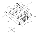
- FIG. 2 is a perspective view of the fixing jig of the embodiment in a closed state.
- FIG. 13 is a diagram showing a state in which a bottle needle is connected to a fixing jig of an embodiment holding a bag.
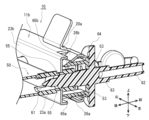
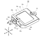
- FIG. 4 is a perspective view of a cross section taken along line AA in FIG. 10 is an explanatory diagram of how a bag is accommodated in the fixing jig of the embodiment, showing the fixing jig in an open state.
- FIG. 10 is an explanatory diagram of a bag being accommodated in the fixing jig of the embodiment, showing the fixing jig in a closed state.
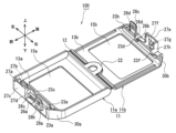
- FIG. 11 is a perspective view of a fixing jig according to a second embodiment in an open state.
- FIG. 2 is a perspective view illustrating the state of the bag before use.
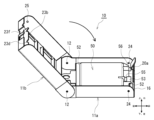
- 13 is a diagram showing a state in which a bottle needle is connected to a fixing jig of the second embodiment holding a bag.
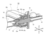
- FIG. FIG. 5 is a cross-sectional view of a fixing jig according to a second embodiment, corresponding to FIG. 4 .
- the bag 50 has a rectangular, flat bag shape.
- the bag 50 is formed by bonding two rectangular films together, and has a main body 51 in which the contents are contained, and a joint 52 that protrudes around the main body 51.
- the bag 50 is formed into a bag shape in which the internal space of the main body 51 is sealed by the joint 52 that surrounds the periphery of the main body 51.
- the main body 51 contains, for example, blood, rare cells, medicine, or biological tissue.
- the bag 50 has a discharge port 53 that protrudes from the end of the main body 51.
- the discharge port 53 is a hollow cylinder that communicates with the internal space of the main body 51, and the tip 54 or the inside of the cylinder is closed by a partition.
- the discharge port 53 is used by inserting a bottle needle 60 from the tip 54 to connect it to the main body 51.
- the discharge port 53 has a reduced diameter portion 55 around its circumference between the main body portion 51 and the tip 54. As described below, the reduced diameter portion 55 is configured to be held by the recesses 23c and 23d provided in the fixing jig 10 when the bag 50 is placed in the fixing jig 10, so that the bag 50 does not move.
- the bag 50 has a filling port 56 adjacent to the discharge port 53 that is connected to the inside of the main body 51.
- the filling port 56 is used when injecting blood, rare cells, biological tissue, etc. into the main body 51.
- the bottle needle 60 is a long, hollow cylinder.
- the bottle needle 60 has a pointed tip 61 at one end, a body 63 extending in the axial direction, and a male connector 62 at the other end, with the body 63 having a flange 64 extending perpendicular to the axial direction.
- the tip 61, male connector 62, body 63, and flange 64 of the bottle needle 60 are integrally molded from a resin such as acrylonitrile butadiene styrene (ABS) resin.
- ABS acrylonitrile butadiene styrene
- the bottle needle 60 has engagement claws 65a, 65b that extend from the flange 64 toward the tip 61. As described below, the engagement claws 65a, 65b are for engaging with the engagement portions 26a, 26b of the fixture 10 when the bottle needle 60 is connected to the discharge port 53.
- the engagement claws 65a, 65b are formed, for example, from polyoxymethylene (POM).
- FIG. 1 is a perspective view showing the appearance of the fixing jig 10, a bag 50, and a bottle needle 60, with the fixing jig 10 in an open state.
- Figure 2 is a perspective view showing the fixing jig 10 in a closed state.
- the directions of up/down, left/right, and front/rear are used merely for the convenience of description, and are not intended to define the direction of use of the fixing jig 10 according to the embodiment.
- the fixing jig 10 includes a frame 11 that holds the bag 50.
- the frame 11 is larger than the bag 50, and has a space inside that can accommodate the bag 50.
- the frame 11 can cover the entire bag 50, including the main body 51, the joint 52, and the discharge port 53.
- the frame 11 can hold the bag 50 by clamping it from both sides in the thickness direction.
- the frame 11 is made of metal, for example aluminum, but is not limited to metal and may be made of a resin that is harder than the discharge port 53.
- the frame body 11 has a first frame body 11a, a second frame body 11b, and a hinge portion 12.
- the frame body 11 has a structure in which the first frame body 11a and the second frame body 11b are connected via the hinge portion 12 so as to be freely opened and closed.
- a bag 50 can be placed on the first frame body 11a or the second frame body 11b, and by closing the frame body 11, the bag 50 is stored inside the frame body 11.
- the frame body 11 has engagement portions 26a, 26b that, while holding the bag 50, engage with the engagement claws 65a, 65b of the bottle needle 60 that is connected to the discharge port 53 of the bag 50, and maintain the connection between the discharge port 53 and the bottle needle 60.
- the frame body 11 is provided with a locking structure for maintaining the first frame body 11a and the second frame body 11b in a closed state.
- the locking structure prevents the frame body 11 from opening easily and prevents the bag 50 held therein from falling off.
- the first frame 11a and the second frame 11b each have a rectangular base 13a, 13b, and have walls around them.
- the frame 11 When the first frame 11a and the second frame 11b are closed, the frame 11 has a box shape as shown in FIG. 2, and can accommodate a bag 50 inside.
- the frame body 11 has openings 15a, 15b at the bases 13a, 13b of the first frame body 11a and the second frame body 11b, which expose the bag 50, and are formed so that the inside of the frame body 11 in the closed state can be visually observed. Furthermore, the frame body 11 has beams 16a, 16b formed to separate the openings 15a, 15b. The beams 16a, 16b prevent the body of the bag 50 from being directly pressed with the fingers when the fixing jig 10 is grasped.
- a drain port connection port 18, a filling port connection port 19, and a hook 20 are formed on the front wall 17 of the frame body 11 in the closed state.
- the discharge port connection port 18 is an opening for connecting the bottle needle 60 to the discharge port 53 when the bag 50 is housed in the frame body 11.
- the filling port connection port 19 is configured to be accessible to the filling port 56 when the bag 50 is housed in the frame body 11.
- the hook 20 forms a locking structure for keeping the frame body 11 closed.
- the hook 20 has a tip 20a that is bent toward the inside of the frame body 11.
- the tip 20a elastically deforms in the front-to-rear direction along the front wall 17, and is fixed in place by elastically returning to its original position when it passes the base 13b.
- the tip 20a hooks onto the base 13b of the second frame body 11b, making it possible to keep the frame body 11 closed.
- a hanging portion 22 is provided on the rear wall 21 of the frame body 11.
- the hanging portion 22 is used to hang the fixture 10 from a stand or the like while holding the bag 50.
- the hanging portion 22 is formed on the first frame body 11a, but it may also be formed on the second frame body 11b.
- the edges of the openings 15a, 15b on the first frame 11a and the second frame 11b are curved inward.
- the curved edges of the openings 15a, 15b on the first frame 11a and the second frame 11b are formed to clamp the main body 51 of the bag 50.
- Each of the first frame body 11a and the second frame body 11b is provided with discharge port support plates 23a, 23b along the edges of the openings 15a, 15b on the front wall 17 side.
- Each discharge port support plate 23a, 23b is formed to sandwich the discharge port 53, the filling port 56, and the joint 52 of the bag 50 when the frame body 11 is closed.
- the ends of the discharge port support plates 23a, 23b of the first frame body 11a and the second frame body 11b respectively have recesses 23c, 23d.
- the recesses 23c, 23d are formed to sandwich the reduced diameter portion 55 of the discharge port 53 when the frame body 11 is closed and the bag 50 is sandwiched. By sandwiching the reduced diameter portion 55 between the recesses 23c, 23d, the bag 50 can be held in an immobile state.
- the ends of the discharge port support plates 23a and 23b are further provided with recesses 23e and 23f.
- the recesses 23e and 23f are provided at positions where the filling port 56 abuts when the frame 11 is closed, and are formed so as to sandwich the filling port 56.
- the frame body 11 has a locking structure for maintaining the closed state in addition to the hook 20 described above.
- Locking holes 24 are formed in the side walls of the first frame body 11a, and locking protrusions 25 are formed in the side walls of the second frame body 11b. When the frame body 11 is closed, the locking protrusions 25 fit into the locking holes 24, maintaining the frame body 11 in a locked state.
- the first frame 11a and the second frame 11b are provided with engagement parts 26a, 26b between the discharge port connection opening 18 and the discharge port support plates 23a, 23b.
- Figure 3 shows the bottle needle 60 inserted to a specified position into the fixture 10 holding the bag 50.
- the engagement claws 65a, 65b of the bottle needle 60 engage with the engagement parts 26a, 26b of the fixture 10, and are fixed so that they cannot come off.
- Figure 4 is a perspective view of the cross section taken along line A-A in Figure 3. It shows the state in which the tip 61 and part of the body 63 of the bottle needle 60 are inserted into the discharge port 53 of the bag 50.
- the engagement claws 65a, 65b of the bottle needle 60 engage with the engagement portions 26a, 26b, and the movement of the bottle needle 60 in the forward and backward directions is restricted.
- the fixing jig 10 is formed so that the bottle needle 60 is inserted to an appropriate depth into the discharge port 53 when inserted to a position where the engagement claws 65a, 65b engage with the engagement portions 26a, 26b.
- the engaging portion 26a of the first frame 11a is bent (upward) toward the inside of the fixing jig 10.
- the engaging portion 26b of the second frame 11b is bent (downward) toward the inside of the fixing jig 10.
- the tip of the engaging portion 26a and the tip of the engaging portion 26b hit the steps of the engaging claws 65a, 65b, so that the bottle needle 60 cannot come out of the fixing jig 10.
- the position of the engagement claws 65a, b when the bottle needle 60 is inserted is determined by the front-to-rear length of the engagement portion 26a of the first frame 11a and the engagement portion 26b of the second frame 11b.
- the depth to which the bottle needle 60 is inserted into the discharge port 53 is determined by the front-to-rear length from the front wall 17 to the discharge port support plates 23a, 23b. Therefore, by appropriately designing these dimensions, the bottle needle 60 can be configured to be inserted to an appropriate depth in the discharge port 53 by pushing it in until the engagement claws 65a, 65b catch on the engagement portions 26a, 26b.
- the engaging portion 26a of the first frame 11a and the engaging portion 26b of the second frame 11b each extend obliquely so that their tips approach each other in the vertical direction. Therefore, the vertical distance between the tip of the engaging portion 26a and the tip of the engaging portion 26b is formed to be narrower than the maximum distance that the engaging claws 65a, 65b extend in the vertical direction. Because it is formed in this way, when the bottle needle 60 is inserted from the discharge port connection port 18, the inclined portions of the tips of the engaging claws 65a, 65b come into contact with the tips of the engaging portions 26a, 26b, and the engaging claws 65a, 65b are inserted while deforming inwardly in the vertical direction.
- the deformation of the engaging claws 65a, 65b returns (elastic return), and the plate portions of the engaging claws 65a, 65b that are parallel to the left and right direction come into contact with the tips of the engaging portions 26a, 26b.
- the vibrations generated when the horizontally parallel plate portions of the engagement claws 65a, 65b hit the tips of the engagement parts 26a, 26b are transmitted to the hand holding the flange 64, allowing the user to confirm that the bottle needle 60 has been inserted to the appropriate length.
- the sound of the horizontally parallel plate portions of the engagement claws 65a, 65b hitting the tips of the engagement parts 26a, 26b can also be used to confirm that the bottle needle 60 has been inserted to the appropriate depth.
- Figure 5 shows the first frame body 11a and the second frame body 11b of the fixing jig 10 in an open state.
- the bag 50 is contained in the first frame body 11a so that the reduced diameter portion 55 of the discharge port 53 fits into the left recess 23c (see Figure 1) of the discharge port support plate 23a of the first frame body 11a and the filling port 56 rests in the right recess 23e.
- the second frame body 11b is moved in the direction of the arrow in the figure around the axis of the hinge portion 12, and the frame body 11 is closed with the reduced diameter portion 55 of the discharge port 53 sandwiched between recesses 23c and 23d, and the filling port 56 sandwiched between recesses 23e and 23f.
- the locking projection 25 of the second frame body 11b fits into the locking hole 24 of the first frame body 11a, and the tip 20a of the hook 20 hooks onto the base 13b of the second frame body 11b, holding the bag 50 (Fig. 6).
- the frame body 11 By configuring the frame body 11 to be openable and closable, the load on the reduced diameter portion 55 of the discharge port 53 when clamping the reduced diameter portion 55 with the recesses 23c and 23d can be reduced. This suppresses deformation of the reduced diameter portion 55, which is the portion engaged with the recesses 23c and 23d, and improves stability when inserting the bottle needle 60.
- the bag 50 is held by the discharge port support plate 23a of the first frame 11a and the discharge port support plate 23b of the second frame 11b.
- the bottle needle 60 is connected to the discharge port connection port 18 of the fixture 10 with the two engagement claws 65a, 65b of the bottle needle 60 aligned vertically.
- the engagement claws 65a, 65b of the bottle needle 60 By pushing the engagement claws 65a, 65b of the bottle needle 60 into the discharge port connection port 18 along the engagement portions 26a, 26b, the bottle needle 60 can be inserted horizontally into the discharge port 53.
- the reduced diameter portion 55 of the discharge port 53 is sandwiched between the recesses 23c, 23d, so that when the tip portion 61 of the bottle needle 60 is inserted into the discharge port 53, the bag 50 and the discharge port 53 are held without moving.
- the main body 51 of the bag 50 can be seen from the opening 15b and the opening 15a on the opposite side.
- the amount of liquid in the bag 50 can be confirmed through the openings 15a and 15b. It can also be confirmed whether the bag 50 is positioned correctly. Furthermore, if the bag 50 is a freezing bag and there is residual frozen liquid inside the bag 50, it can be sent out without leaving any liquid behind by kneading the bag 50 through the openings 15a and 15b.
- the beams 16a and 16b between the openings 15a and 15b serve to maintain the strength of the first frame 11a and the second frame 11b, and also serve to prevent the main body 51 of the bag 50 from being pressed directly with the fingers when handling the fixing jig 10 by hand.
- the engagement portions 26a, 26b of the frame body 11 holding the bag 50 engage with the engagement claws 65a, 65b of the bottle needle 60, so that the bottle needle 60 connected to the discharge port 53 can be prevented from coming loose.
- the fixing jig 10 of this embodiment has a hanging portion 22 integrally provided on the rear wall 21 of the first frame 11a. Because the hanging portion 22 is formed integrally with the fixing jig 10, the fixing jig 10 holding the bag 50 can be easily hung from a stand or the like. Although the hanging portion 22 is positioned in the center of the rear wall 21 in Figures 1 and 6, it does not necessarily have to be in such a location. Any arrangement is acceptable as long as the components of the bag 50 flow toward the male connector portion 62 of the bottle needle 60 when hanging from the stand.
- the fixing jig 10 of this embodiment is provided with a hook 20, as shown in Figures 1 and 6.
- the hook 20 acts to prevent the first frame body 11a and the second frame body 11b from opening easily.
- the fixing jig 10 is used by hanging it, the hook 20 prevents the fixing jig 10 from opening easily, thereby preventing the bag 50 from falling.
- the hinge portion 12 is disposed in the rear direction of the side wall of the first frame body 11a and the second frame body 11b. Therefore, the first frame body 11a and the second frame body 11b are opened and closed by opening the front side with the hinge portion 12 as an axis.
- the opening and closing direction of the first frame body 11a and the second frame body 11b is not limited to this.
- the hinge portion 12 may be disposed in the front direction of the side wall and opened at the rear side. With this configuration, it is possible to prevent the bag 50 from easily falling even when the first frame body 11a and the second frame body 11b are not closed.
- the first frame body 11a and the second frame body 11b may be configured to open in the left and right directions.
- the hinge configuration is well known and various modifications are possible.
- the first frame body 11a and the second frame body 11b may be configured to be separated into two members without being connected by a hinge.
- the hinge portion 12 protrudes rearward from the side walls of the first frame body 11a and the second frame body 11b, and is configured so that the hanging portion 22 does not come into contact with the second frame body 11b when opening and closing.
- the bag 50 does not necessarily have to protrude, and the second frame body 11b may be configured to come into contact with the hanging portion 22 when opening and closing.
- the openings 15a, 15b are defined by the beams 16a, 16b of the first frame 11a and the second frame 11b, but the width, location, and number of the beams 16a, 16b are not limited to this. Therefore, there may be two or more beams 16a, 16b, and the width of the defined openings 15a, 15b need not be uniform. Also, the beams 16a, 16b do not have to be present. As long as the amount and arrangement of liquid in the bag 50 can be visually confirmed by the openings 15a, 15b when the bag 50 is used for infusion, and as long as the bag 50 is a freezing bag and the bag 50 can be kneaded when there is residual frozen material, the configuration is not limited to the above configuration and drawings.
- the bag 50 when the fixing jig 10 is closed, the bag 50 is surrounded by the side walls and rear wall 17 of the first frame body 11a and the second frame body 11b. This makes it easier to position the bag 50 and reduces the risk of accidentally touching the bag 50.
- the walls of the fixing jig 10 are not necessarily required. If there are no walls, visibility from the side is improved and the position of the bag 50 can be confirmed from more angles.
- the fixing jig 10 does not necessarily have to hold the entire bag 50, but may hold only a portion of it, or may be configured to hold only the discharge port 53. Specifically, it is sufficient that the recesses (first engagement portions) 23c, 23d of the discharge port support plates 23a, 23b sandwich and hold the reduced diameter portion (first engaged portion) 55 of the discharge port 53, and that the engagement portions (second engagement portions) 26a, 26b of the frame body 11 engage with the engagement claws (second engaged portions) 65a, 65b of the bottle needle 60.
- the fixing jig 10 is made of a harder material than the discharge port 53, when the discharge port 53 is attached, the recesses (first engagement portions) 23c, 23d and the engagement portions (second engagement portions) 26a, 26b of the discharge port support plates 23a, 23b can prevent the bottle needle 60 from slipping out of the discharge port 53.
- the edges of the openings 15a, 15b and the discharge port support plates 23a, 23b are formed continuously across the entire openings 15a, 15b, but this configuration is not necessarily required. In other words, as long as the bag 50 can be held and the reduced diameter portion 55 of the discharge port 53 and the filling port 56 can be fixed, the edges and the discharge port support plates 23a, 23b may be configured intermittently.
- the fixing jig 10 fixes the first frame body 11a and the second frame body 11b by fitting the locking holes 24 and the locking protrusions 25 and by hooking the hooks 20, but this configuration is not necessarily required. Only one of the locking mechanisms may be used, and locking mechanisms may be added as necessary in addition to the locking holes 24, the locking protrusions 25, and the hooks 20, and the embodiment is not limited to the above.
- Second Embodiment A fixing jig 100 according to a second embodiment of the present disclosure will be described with reference to Figures 7A, 7B, and 8.
- components similar to those in the first embodiment are denoted by the same reference numerals as in the first embodiment, and detailed description thereof will be omitted.
- the fixing jig 100 of the second embodiment is integrally formed from a resin material, such as polypropylene, that is harder than the discharge port 53. By forming it from resin, the fixing jig 100 can be formed more compactly and is lighter than the fixing jig 10 of the first embodiment. By forming it integrally from resin, it is also easier to manufacture. This is explained in detail below.
- the frame body 11 of the second embodiment has a first frame body 11a and a second frame body 11b, as in the first embodiment.
- the first frame body 11a has a base 13a
- the base 13a has an opening 15a.
- the second frame body 11b has a base 13b and an opening 15b.
- the opening 15a of the first frame body 11a and the opening 15b of the second frame body 11b of the second embodiment do not have a beam.
- the reason is that since the frame body 11 is made of resin and is compact, it is easy to hold the bag without touching the places where the beams can be provided with your fingers, but since the openings 15a and 15b are small, providing the beams would reduce the visibility of the bag 50.
- the presence or absence of the beams is not particularly limited, and they may be provided as appropriate.
- the first frame 11a is similarly formed with a hanging portion 22.
- the use of the hanging portion 22 is the same as in the first embodiment, and the hanging portion 22 may be provided on the second frame 11b.
- a discharge port support plate 23a In front of the opening 15a of the first frame 11a, a discharge port support plate 23a is formed, and in the corresponding portion of the second frame 11b, a discharge port support plate 23b is formed.
- Two recesses 23c, 23d are formed in the discharge port support plates 23a, 23b. As in the first embodiment, the recesses 23c, 23d are configured to sandwich the reduced diameter portion 55 of the bag 50.
- the ends of the discharge port support plates 23a, 23b are further formed with recesses 23e, 23f, which are also similarly configured to sandwich the filling port 56.
- the discharge port support plates 23a, 23b do not need to be continuous, and the discharge port support plates 23a, 23b may be configured to exist only near the recesses.
- the configuration described above has the same configuration and function as the first embodiment.
- the frame body 11 is integrally formed from a resin material.
- the first frame body 11a and the second frame body 11b are connected by the hinge portion 12.
- the hinge portion 12 allows the first frame body 11a and the second frame body 11b to be rotatable, and the bag 50 can be held and closed while being housed in the base portion 13a and the base portion 13b.
- the frame body 11 is configured to be openable and closable, so that the load on the reduced diameter portion 55 of the discharge port 53 can be reduced when the reduced diameter portion 55 is clamped between the recesses 23c and 23d. This suppresses deformation of the reduced diameter portion 55, which is the engaged portion with the recesses 23c and 23d, and improves stability when inserting the bottle needle 60.
- the frame 11 of the fixing jig 100 is made of resin, so it can be made more compact and lightweight than the fixing jig 10 of the first embodiment. Being compact and lightweight has the advantage that the fixing jig 100 is easy to hold.
- the fixing jig 100 of the second embodiment has locking claws 27a, 27e and locking windows 28a, 28c on the front edges of the first frame body 11a and the second frame body 11b.
- the locking claws 27a, 27e and the locking windows 28a, 28c form the locking structure of the fixing jig 100.
- the first frame 11a has a locking claw 27a formed at the left end on the front edge, and an engagement portion 26a, a window portion 26c, and a locking window 28a are formed along the edge.
- the corresponding portion of the second frame 11b has a locking window 28c, an engagement portion 26b, a window portion 26d, and a locking claw 27e.
- the structure of the engagement portions 26a and 26b will be described later.
- the locking claws 27a, 27e and the locking windows 28a, 28c are formed in a staggered manner.
- the locking claws and locking windows are formed in a staggered manner because the frame body 11 is made of resin, and this is to prevent the frame body 11 from opening if the locking claws or locking windows are broken or unexpectedly deformed. Therefore, as long as the frame body 11 can be prevented from opening, the configuration is not limited to this.
- the locking claw 27a of the first frame 11a has a wall portion 27c extending vertically from the edge of the base 13a of the first frame 11a, a claw portion 27b provided in the center of the wall portion 27c, and side wall portions 27d on the left and right sides of the wall portion 27c.
- the locking claw 27a is configured to fit into the locking window 28c of the second frame 11b.
- the locking window 28c of the second frame 11b is a plate-like member that extends vertically from the edge of the base 13b of the second frame 11b, and has a window portion 28d in approximately the center of the plate-like portion.
- the outer shape of the locking window 28c is formed to correspond to the wall portion 27c and side wall portion 27d of the locking claw 27a. It is formed so that the claw portion 27b of the locking claw 27a fits into the window portion 28d of the locking window 28c when the frame 11 is closed.
- the locking claw 27e of the second frame 11b is formed in the same manner as the locking claw 27a.
- the locking window 28a of the first frame 11a is formed in the same manner as the locking window 28c.
- the locking claws 27a, 27e and the locking windows 28a, 28c engage with each other, and are formed with a locking structure that will not come loose once engaged.
- the fixing jig 100 of this embodiment further includes a structure for preventing the bag 50 from being erroneously attached before use.
- FIG. 7B is a diagram illustrating the state of the bag 50 before use. Before use, the tip 54 of the discharge port 53 of the bag 50 is protected by a protective sheet 57, shown by a dashed line, which is integral with the joint 52 that surrounds the periphery of the main body 51.
- the fixing jig 100 of this embodiment has a locking structure, so if the bag 50 is attached to the fixing jig 100 with the protective sheet 57 still attached, the internal solution of the bag 50 cannot be taken out and the bag must be discarded in vain. Therefore, in order to prevent incorrect attachment, the fixing jig 100 of this embodiment has the side wall portion 27d of the locking claw 27a extended laterally (to the right). When the bag 50 without the protective sheet 57 is placed on the first frame 11a, the protective sheet 57 interferes with the side wall portion 27d and cannot be set on the first frame 11a.
- the side wall portion 27h of the locking claw 27e is also extended laterally (to the left).
- the side wall 27h also interferes with the protective sheet 57, preventing incorrect installation.
- the structure to prevent incorrect installation may be such that the extended portion of the side wall 27h is provided on the first frame 11a side.
- Figure 8 shows the state in which the frame 11 of the fixing jig 100 of the second embodiment is closed to hold the bag 50 and connect the bottle needle 60. Since the fixing jig 100 of this embodiment is made of resin, the bag 50 can be discarded in the state shown in Figure 8 after use. Therefore, the locking structure is a fixed engagement structure.
- the engagement parts 26a, 26b of the fixing jig 100 of the second embodiment are formed by varying the thickness of the edges of the first frame body 11a and the second frame body 11b.
- the thickness of the engagement parts 26a, 26b is thinnest at the front as shown in Figure 9, and forms a gradient so that the thickness increases toward the rear (the connection direction of the bottle needle 60).
- the vertical spacing between the engagement parts 26a, 26b is widest at the front end and narrows toward the rear.
- the effect of the engagement claws 65a, 65b of the bottle needle 60 engaging with the engagement portions 26a, 26b, restricting the movement of the bottle needle 60 in the forward and backward directions is the same as in the first embodiment.
- the vibration or sound produced when the parallel parts of the engagement claws 65a, 65b in the left-right direction hit the tips of the engagement portions 26a, 26b allows confirmation that the bottle needle 60 has been inserted to the appropriate depth.
- the finger rests 29a, 29b provided on the first frame 11a and the second frame 11b will be described.
- the finger rests 29a, 29b are constricted so that they approach each other in the vertical direction from the front to the rear.
- This shape brings the bases 13a, 13b of the frame 11 closer to the main body 51 of the bag 50 in the vertical direction than the front edges of the first frame 11a and the second frame 11b to which the bottle needle 60 is connected, so that the bases 13a, 13b abut against or are slightly separated from the main body 51. Therefore, when the frame 11 holds the bag 50, the vertical movement of the body 51 can be restricted, improving stability when gripping the frame 11.
- the finger rests 29a and 29b have a curved shape that fits the fingers when the fixing jig 100 is gripped.
- the fixing jig 100 alone can hold the bag 50, but by gripping the frame body 11 with the fingers gripping the finger rests 29a and 29b, the opening between the discharge port support plates 23a and 23b and the reduced diameter portion 55 can be suppressed, thereby further improving operability.
- the finger rests 29a and 29b are not limited to the curved shapes shown in Figures 8 and 9.
- each of the finger rests 29a and 29b may be formed in a slope shape that approaches linearly in the vertical direction from the front to the rear, or a stepped shape with multiple steps from the front to the rear.
- the fixing jig 100 of this embodiment has a means for preventing the bottle needle from being inserted too far.
- the inclination of the tip portion of the engaging claws 65a, 65b is configured to abut against the convex portion on the back side of the finger rest portions 29a, 29b. This prevents the bottle needle 60 from being inserted too far into the discharge port 53.
- the front edge of the frame body 11 on which the engaging portions 26a, 26b are formed also serves to prevent the bottle needle 60 from being inserted too far into the discharge port 53 by abutting against the flange portion 64 of the bottle needle 60.
- the fixing jig 10 of the first embodiment can also be configured to function as a means for preventing the bottle needle from being inserted too far by adjusting the engaging portions 26a, 26b and the discharge port support plates 23a, 23b.
- the fixing jig 100 of the second embodiment holds the bag 50 immovably by using the bases 13a and 13b to hold it in place, but the openings 15a and 15b may also be configured to hold the bag 50 by providing edges that face the inside of the frame body 11.
- the fixing jig 100 may hold only a part of the bag 50, rather than the entire bag 50, or may be configured to hold only the discharge port 53. Specifically, it is sufficient that the recesses (first engagement portion) 23c, 23d of the discharge port support plates 23a, 23b sandwich and hold the reduced diameter portion (first engaged portion) 55 of the discharge port 53, and that the engagement portions (second engagement portion) 26a, 26b of the frame body 11 engage with the engagement claws (second engaged portion) 65a, 65b of the bottle needle 60.
- the fixing jig 100 is made of a harder material than the discharge port 53, when the discharge port 53 is attached, the recesses (first engagement portion) 23c, 23d and the engagement portions (second engagement portion) 26a, 26b of the discharge port support plates 23a, 23b can prevent the bottle needle 60 from slipping out of the discharge port 53.
- the fixing jig 100 of the second embodiment has triangular portions 30a, 30b on the first frame body 11a and the second frame body 11b, respectively.
- the triangular portions 30a, 30b are provided to correspond to the triangular cutout portion of the bag 50, and the orientation of the bag 50 can be easily confirmed when placing the bag 50 in the frame body 11.
- the triangular portions 30a, 30b are not essential components.
- the fixing jigs 10 and 100 described above are configured to open and close the frame body 11, but are not limited to this.
- one of the left and right walls of the frame body 11 may be opened, and the discharge port 53 may be slid from the open side to be attached.
- the discharge port support plates 23a and 23b are provided with a gap inside the frame body 11 where the discharge port 53 is attached, and the reduced diameter portion 55 of the discharge port 53 is slid along the end faces of the discharge port support plates 23a and 23b to be attached.
- the gap between the discharge port support plates 23a and 23b may be narrowed to ensure that the discharge port 53 is fixed securely.
- the bag may be positioned and held in the fixing jig by sliding it from the side of the bag, or a part of the fixing jig may be made of an elastic member to surround the bag and hold it by elastic force. It may hold part of the bag, or it may hold only the port.
- the engagement mechanism between the fixing jig and the bottle needle is not limited to a locking claw, but may be a physical fit using projections and recesses, a screw fit, etc. It goes without saying that the configuration of the fixing jig is not limited to these.
Landscapes
- Health & Medical Sciences (AREA)
- Pharmacology & Pharmacy (AREA)
- Life Sciences & Earth Sciences (AREA)
- Animal Behavior & Ethology (AREA)
- General Health & Medical Sciences (AREA)
- Public Health (AREA)
- Veterinary Medicine (AREA)
- Medical Preparation Storing Or Oral Administration Devices (AREA)
Abstract
固定治具(10)は、バッグ(50)を保持可能な枠体(11)を有し、枠体(11)は、バッグ(50)の排出ポート(53)に接続されるびん針(60)の係合爪(65a、65b)と係合し、びん針(60)の接続状態を保持する係合部(26a、26b)を有する。軟質の排出ポート(53)に固定される固定治具は、排出ポート(53)より硬質に形成され、排出ポート(53)に装着可能であると共に排出ポート(53)の装着時において排出ポート(53)に形成された第一被係合部(55)と係合し得る第一係合部(23c、23d)と、びん針(60)に形成された第二被係合部(65a、65b)と係合し得る第二係合部(26a、26b)とを有し、第一係合部(23c、23d)及び第二係合部(26a、26b)を介してびん針(60)が排出ポート(53)から抜け出ることを防止する。
Description
本開示は、医療用のバッグを保持するための固定治具に関する。
医療用のバッグには様々な形態が存在し、血液、稀少細胞及び生体組織などを凍結して保存するための凍結バッグや血液や血液成分を分離することを目的とした血液バッグなどが知られている。上述した様々な医療用のバッグも輸液容器(輸液バッグ)と同様に、点滴での使用が行われるようになってきている。
特許文献1には、輸液容器のメスコネクタ(排出ポート)の径大部にびん針(穿刺針)の係合爪が係合する接続構造が記載されている。
特許文献1に記載のメスコネクタ(排出ポート)の径大部は輸液容器によって係合部分の面積が異なり、特に係合面積が小さい場合は外力によって係合爪が外れることがある。びん針がメスコネクタ(排出ポート)から抜けると、輸液容器内の液が外に漏れるという課題がある。
特に、筒状内部に隔壁を一体で形成した排出ポートを有するバッグについては、隔壁をびん針で貫通させるため、排出ポートは柔らかい材質で形成する必要がある。また凍結保存用の凍結バッグについては、凍結時の破損を防止するために排出ポートも柔らかい材質で形成する必要があり、このような軟質の排出ポートにおいてコネクタの脱離は問題となりやすい。排出ポートにびん針を穿刺する工程は穿刺という操作上、ブレなく排出ポートに対してびん針を正確に水平移動させることは困難であり、穿刺作業中に排出ポートの係合部分に負荷を加えてしまい、微小な変形を生じさせてしまう場合がある。結果、係合爪との係合強度が落ちて、びん針が排出ポートから抜けるという課題がある。
また、輸液容器が可撓性のバッグである場合、使用者はポートを把持しようとするが、ポートは小型であるため、持ちにくく、穿刺操作しにくい。把持可能な面積が大きいバッグを把持することが考えられるが、バッグへの外力が容器内の液体に及び、穿刺時にバッグ内の液体が外に漏れる可能性がある。
本開示の目的は、上記課題の少なくとも一つを解決することであって、排出ポートから液が漏れにくい固定治具を提供することである。
本開示に係る固定治具は、バッグを保持可能な枠体を備える。枠体は、排出ポートに接続されるびん針と係合し、びん針の接続状態を保持する係合部を有することを特徴とする。
上記構成によれば、バッグを保持した枠体の係合部とびん針が係合するので、排出ポートに接続された状態のびん針が外れることを防止できる。また、係合時に、使用者はバッグではなく枠体を把持することができるため操作の安定性が向上する。
本開示の一態様である固定治具の枠体は、更に吊下げ部を有してもよい。
上記構成によれば、固定治具が吊下げ部を有するので、バッグを保持した状態でスタンドに吊り下げることが容易になる。
本開示の一態様である固定治具の枠体は、バッグを露出させる開口部を有してもよい。
上記構成によれば、開口部からバッグの液量の状態を容易に確認することができる。
本開示の一態様である固定治具は、枠体が開閉可能に構成され、枠体を閉じて、バッグを保持した状態を維持する係止構造を有してもよい。
上記構成によれば、枠体は容易に開くことが無く、保持したバッグが落ちることを防ぐことができる。
本開示の一態様である固定治具の枠体は、排出ポートにびん針を挿入したとき、びん針の一部と当接することでびん針の過度の挿入を阻止する挿し過ぎ防止手段を有してもよい。
上記構成によれば、排出ポートへのびん針の挿し過ぎが防止できる。
本開示に係る固定治具は、筒状内部に隔壁を一体で形成した排出ポート又は凍結保存用の凍結バッグに設けられた排出ポートに取り付けられる固定治具であって、前記排出ポートより硬質に形成され、前記排出ポートに装着可能であると共に、装着時において、前記排出ポートに形成された第一被係合部と係合しうる第一係合部と、前記びん針に形成された第二被係合部と係合しうる第二係合部とを有し、前記第一係合部及び前記第二係合部を介して、前記びん針が前記排出ポートから抜け出ることを防止することを特徴とする。
上記構成によれば、排出ポートに係合部材を係合させる工程と、びん針の穿刺操作とを分けることができ、排出ポートの被係合部に負荷をかけ、変形させてしまう事態を低減できる。また、排出ポートに取り付けられる固定治具は排出ポートより硬質であると、硬質である固定治具にびん針との係合部を有するため、びん針と安定的に係合することができ、排出ポートに接続された状態のびん針が外れることを防止できる。
本開示の一態様である固定治具は、開閉可能に構成され、枠体を閉じて、排出ポートを保持する係止構造を有してもよい。開閉可能であることで、排出ポートに係合させる際に、被係合部に負荷がかかることを一層低減できる。
本開示に係る固定治具によれば、排出ポートに接続されたびん針が外れることを防止できる。
以下、本開示の実施形態について、図面を参照しながら詳細に説明する。以下の説明において、具体的な形状、材料、方向、数値等は、本開示の理解を容易にするための例示であって、用途、目的、仕様等に合わせて適宜変更することができる。また、以下で説明する実施形態及び変形例の構成要素を選択的に組み合わせることは当初から想定されている。
初めに本開示の実施形態の固定治具10で扱うバッグ50とびん針60の構成について説明する。
バッグ50は、図1に示すように矩形で扁平な袋状をしている。バッグ50は、2つの矩形のフィルムを張り合わせて形成され、内容物が収容される本体部51と、本体部51の周囲に張り出した接合部52とを有する。バッグ50は、本体部51の周りを囲む接合部52により、本体部51の内部空間が密閉された袋状に形成されている。本体部51には、例えば血液、稀少細胞、薬剤、または生体組織などが収容されている。
バッグ50は、本体部51の端から突出する排出ポート53を有する。排出ポート53は、本体部51の内部空間に連通した中空の筒状をしており、先端54または筒状の内部が隔壁で閉じられている。排出ポート53は、内部溶液を取り出す際に、びん針60を先端54から挿し込んで本体部51と連通させて使用される。
排出ポート53は、本体部51と先端54の間で周回りに縮径部55を有している。後述するように、縮径部55は、バッグ50を固定治具10に収容した際に、固定治具10に設けた凹部23c、23dによって保持され、バッグ50が動かないように構成されている。
バッグ50は、排出ポート53に隣接して、本体部51の内部に連通する充填ポート56を有している。充填ポート56は、本体部51に血液、稀少細胞及び生体組織などを注入する際に使用される。
次にびん針60について説明する。びん針60は、細長い中空の筒状をしている。びん針60は、一端が尖った先端部61と、軸方向に延びる胴体部63と、他端にオスコネクタ部62を有し、胴体部63において、軸方向に垂直に延びる鍔部64を有している。びん針60の先端部61、オスコネクタ部62、胴体部63、鍔部64は、例えばアクリロニトリル・ブタジエン・スチレン(ABS)樹脂等の樹脂で一体成形されている。
びん針60は、鍔部64から先端部61の方向に延びる係合爪65a、65bを有している。係合爪65a、65bは、後述するように、びん針60を排出ポート53に接続したとき、固定治具10の係合部26a、26bと係合するためのものである。係合爪65a、65bは、例えば、ポリオキシメチレン(POM)等で形成されている。
<第1実施形態>
図1及び図2を参照して、本開示の第1の実施形態の固定治具10について説明する。図1は、固定治具10、バッグ50とびん針60の外観を示す斜視図であって、固定治具10を開いた状態を示す。図2は、固定治具10を閉じた状態の斜視図である。以下の説明における、上下、左右、前後の方向は、説明のために便宜上使用しているに過ぎず、実施形態に係る固定治具10の使用方向を規定する趣旨ではない。
図1及び図2を参照して、本開示の第1の実施形態の固定治具10について説明する。図1は、固定治具10、バッグ50とびん針60の外観を示す斜視図であって、固定治具10を開いた状態を示す。図2は、固定治具10を閉じた状態の斜視図である。以下の説明における、上下、左右、前後の方向は、説明のために便宜上使用しているに過ぎず、実施形態に係る固定治具10の使用方向を規定する趣旨ではない。
固定治具10は、バッグ50を保持する枠体11を備える。枠体11は、バッグ50より大きく、その内部にはバッグ50を収容可能な空間が設けられている。枠体11は、本体部51、接合部52、及び排出ポート53を含むバッグ50の全体を覆うことが可能である。そして、枠体11がバッグ50を厚み方向両側から挟持することにより、バッグ50を保持することができる。枠体11は、金属製、例えばアルミ製の枠体であるが、金属に限らず、排出ポート53よりも硬質の樹脂で構成されてもよい。
枠体11は、第1枠体11aと、第2枠体11bと、ヒンジ部12とを有する。枠体11は、第1枠体11aと第2枠体11bがヒンジ部12を介して開閉自在に連結された構造を有する。枠体11が開いた状態で、第1枠体11aまたは第2枠体11bにバッグ50を載せることができ、枠体11を閉じることにより枠体11の内部にバッグ50が収容される。
枠体11は、バッグ50を保持した状態で、バッグ50の排出ポート53に接続されるびん針60の係合爪65a、65bと係合し、排出ポート53とびん針60の接続状態を保持する係合部26a、26bを有している。
更に枠体11には、第1枠体11aと第2枠体11bが閉じた状態を維持するための係止構造が設けられている。係止構造によって、枠体11は容易に開くことが無く、保持したバッグ50を落とすことが無いように構成されている。
次に枠体11、第1枠体11a及び第2枠体11bの詳細について説明する。
第1枠体11a及び第2枠体11bは、それぞれ矩形の基部13a、13bを有し、周囲に壁を有している。枠体11は、第1枠体11aと第2枠体11bを閉じた状態で、図2に示すように箱形を呈し、その内部にバッグ50を収容することができる。
枠体11は、第1枠体11aと第2枠体11bの基部13a、13bにおいて、バッグ50を露出させる開口部15a、15bが設けられ、閉じた状態の枠体11の内部が目視可能に形成されている。更に枠体11は、開口部15a、15bを区画するように形成された梁部16a、16bを有している。梁部16a、16bによって、固定治具10を把持する際に、バッグ50の本体を直接指で押さえることを防ぐことができる。
図2に示すように、閉じた状態の枠体11の前方向の壁17には、排出ポート接続口18、充填ポート接続口19及びフック20が形成されている。
排出ポート接続口18は、枠体11にバッグ50を収容した状態で、排出ポート53にびん針60を接続するための開口である。
同様に充填ポート接続口19は、枠体11にバッグ50を収容した状態で、充填ポート56にアクセス可能に構成されている。
フック20は、枠体11を閉じた状態を維持するための係止構造を構成している。フック20は、枠体11の内側に曲がった先端部20aを有している。枠体11を閉じる際、前方の壁17に沿って先端部20aが前後方向へ弾性変形し、基部13bを超えたときに先端部20aが弾性復帰することで固定される。これにより、枠体11を閉じた状態で、第2枠体11bの基部13bに先端部20aが引っ掛かり、枠体11を閉じた状態に維持することが可能である。
枠体11の後方の壁21には、吊下げ部22が設けられている。吊下げ部22は、バッグ50を保持した状態で、固定治具10をスタンド等に吊下げるために用いられる。図1の固定治具10においては、吊下げ部22は、第1枠体11aに形成されているが、第2枠体11bに形成するようにしてもよい。
次に図1を参照して、枠体11内部におけるバッグ50の保持構造について、更に説明する。
第1枠体11a及び第2枠体11bに設けられた開口部15a、15bの縁は、内側に曲がっている。バッグ50を内部に収容して枠体11を閉じたとき、第1枠体11aと第2枠体11bのそれぞれの開口部15a、15bの曲がった縁が、バッグ50の本体部51を挟持するように形成されている。
第1枠体11a及び第2枠体11bのそれぞれは、前方向の壁17側に、開口部15a、15bの縁に沿って、排出ポート支持板23a、23bが設けられている。それぞれの排出ポート支持板23a、23bは、枠体11を閉じたときに、バッグ50の排出ポート53、充填ポート56及び接合部52を挟持するように形成されている。
第1枠体11a及び第2枠体11bのそれぞれの排出ポート支持板23a、23bの端部には、凹部23c、23dを有している。凹部23c、23dは、枠体11を閉じてバッグ50を挟持したときに、排出ポート53の縮径部55を挟むように形成されている。凹部23c、23dで縮径部55を挟むことにより、バッグ50が動かない状態で保持することができる。
排出ポート支持板23a、23bの端部には、更に凹部23e、23fが設けられている。凹部23e、23fは、枠体11を閉じた状態で、充填ポート56が当接する位置に設けられ、充填ポート56を挟むように形成されている。
図1の固定治具10においては、枠体11は、先述のフック20に加えて、閉じた状態を維持する係止構造を有している。第1枠体11aの側方の壁に係止孔24が形成され、第2枠体11bの側方の壁に係止突起25が形成されている。枠体11を閉じたときに係止突起25が係止孔24に嵌って、枠体11の係止状態が維持される。
第1枠体11a及び第2枠体11bには、排出ポート接続口18と排出ポート支持板23a、23bの間に、係合部26a、26bが設けられている。このように係合部26a、26bを設けたことで、バッグ50を挟持した固定治具10にびん針60が接続されると同時に、係合爪65a、65bが、係合部26a、26bと係合して、固定治具10から外れない構造となっている。
次に図3、4を参照して、固定治具10におけるびん針60の係合構造について説明する。
図3は、バッグ50を保持した固定治具10にびん針60を所定位置まで挿し込んだ状態を示す。この状態で、びん針60の係合爪65a、65bが固定治具10の係合部26a、26bと係合し、外れないように固定されている。
図4は、図3におけるA-A線断面の斜視図である。バッグ50の排出ポート53にびん針60の先端部61と胴体部63の一部が挿し込まれた状態を示している。びん針60の係合爪65a、65bは、係合部26a、26bと係合し、びん針60は前後方向への動きが規制されている。係合部26a、26bに係合爪65a、65bが係合する位置まで挿し込んだ状態で、排出ポート53へのびん針60の挿し込みが適切な深さになるように、固定治具10は形成されている。
第1枠体11aの係合部26aは、固定治具10の内部方向(上方向)に曲げて形成されている。同様に第2枠体11bの係合部26bは、固定治具10の内部方向(下方向)に曲げて形成されている。係合部26aの先端と係合部26bの先端が、係合爪65a、65bの段差に当たることにより、びん針60は固定治具10から抜けない構造となっている。
本実施形態の固定治具10は、第1枠体11aの係合部26aと第2枠体11bの係合部26bの前後方向の長さによって、びん針60が挿し込まれたときの係合爪65a、bの位置が決まる。前方向の壁17から排出ポート支持板23a、23bまでの前後方向の長さによって、排出ポート53に挿し込まれるびん針60の挿し込みの深さが決まる。従って、これらの寸法を適切に設計することで、係合部26a、26bに係合爪65a、65bが引っ掛かるまで押し込むことによって、びん針60が排出ポート53の適切な深さまで挿し込まれるように構成することができる。
第1枠体11aの係合部26aと第2枠体11bの係合部26bは、それぞれ上下方向へ先端同士が近づくように斜めに延出している。よって、係合部26aの先端と係合部26bの先端の上下方向の間隔は、係合爪65a、65bが上下方向に張り出した最大間隔より狭く形成している。このように形成したので、排出ポート接続口18からびん針60を挿し込む際に、係合爪65a、65bの先端の傾斜部分が係合部26a、26bの先端に当り、係合爪65a、65bは上下方向の内側に変形しながら挿し込まれる。係合爪65a、65bの最大間隔の部分が、係合部26a、26bの先端を超えると、係合爪65a、65bの変形が戻り(弾性復帰し)、係合爪65a、65bの左右方向に平行な板部分が係合部26a、26bの先端に当接する。係合爪65a、65bの左右方向に平行な板部分が係合部26a、26bの先端に当たるときの振動は、鍔部64を把持している手に伝わり、びん針60が適切な長さに挿し込まれたことが確認できる。また、材質によるが、係合爪65a、65bの左右方向に平行な板部分が係合部26a、26bの先端に当たる音によっても、びん針60が適切な深さに挿し込まれたことを確認することができる。
図5及び図6を参照して、本実施形態の固定治具10にバッグ50を収容し、びん針60を取付ける方法について説明する。
図5は、固定治具10の第1枠体11aと第2枠体11bを開いた状態の図である。第1枠体11aの排出ポート支持板23aの左側の凹部23c(図1参照)に排出ポート53の縮径部55が嵌り、右側の凹部23eに充填ポート56が載るように、第1枠体11aにバッグ50を収容する。この状態から、ヒンジ部12の軸周りに図中矢印の方向に第2枠体11bを動かして、凹部23cと凹部23dで排出ポート53の縮径部55を挟み、凹部23eと凹部23fで充填ポート56を挟んで枠体11は閉じられる。枠体11を閉じた状態で、第2枠体11bの係止突起25が、第1枠体11aの係止孔24に嵌り、フック20の先端部20aが、第2枠体11bの基部13bに引っ掛かかって、バッグ50が保持された状態となる(図6)。枠体11を開閉可能に構成したことにより、排出ポート53の縮径部55を凹部23c、23dで挟持する作業において、縮径部55に負荷がかかることを低減できる。これによって、凹部23c、23dとの被係合部である縮径部55の変形が抑制され、びん針60を挿し込む際の安定性を向上させることができる。
図6に示す状態において、バッグ50は、第1枠体11aの排出ポート支持板23aと第2枠体11bの排出ポート支持板23bによって保持されている。この状態で、びん針60の2つの係合爪65a、65bが、上下方向に並ぶようにして、びん針60を固定治具10の排出ポート接続口18から接続する。びん針60の係合爪65a、65bを係合部26a、26bに沿って排出ポート接続口18に押し込むことで、びん針60を排出ポート53に水平に差し込むことが可能である。上述したように、凹部23c、23dで排出ポート53の縮径部55を挟んでいるので、びん針60の先端部61を、排出ポート53に挿し込むとき、バッグ50及び排出ポート53は動くことなく保持される。
図6に示すように、開口部15b及び反対側の開口部15aから、バッグ50の本体部51が確認できる。バッグ50を点滴に使用した際に、開口部15a、15bによって、バッグ50の液量が確認できる。また、バッグ50の配置が正常であるかどうかも確認することができる。さらに、バッグ50が凍結バッグで、バッグ50内で凍結残りが有る場合は、開口部15a、15bからバッグ50を揉むことで、液体を残すことなく送り出すことができる。開口部15a、15bの間の梁部16a、16bは、第1枠体11a、第2枠体11bの強度を保つ役割を有するとともに、固定治具10を手で扱う際に、バッグ50の本体部51を直接指で押さえない役目も果たす。
以上説明したように、本実施形態の固定治具10によれば、バッグ50を保持した枠体11の係合部26a、26bとびん針60の係合爪65a、65bが係合するので、排出ポート53に接続された状態のびん針60が外れることを防止できる。
また、本実施形態の固定治具10は、図1、6に示すように、固定治具10には、第1枠体11aの後方の壁21に一体的に吊下げ部22が設けられている。吊下げ部22が、固定治具10と一体に形成されているために、バッグ50を保持した状態の固定治具10を、容易にスタンド等へ吊下げることができる。吊下げ部22は図1、6では後方の壁21の中央部分に配置されているが、必ずしもそのような場所でなくてもよい。スタンドへ吊下げる際にバッグ50の成分がびん針60のオスコネクタ部62側へ流動するような構成であればどのような配置であってもよい。
更に、本実施形態の固定治具10は、図1、6に示すように、フック20が設けられている。バッグ50を保持した状態において、フック20は、第1枠体11aと第2枠体11bが容易に開かない様に作用する。フック20により、固定治具10を吊下げて使用したとき、固定治具10が容易に開くことが無いので、バッグ50の落下を防止できる。
上述の実施形態では、ヒンジ部12は、第1枠体11aと第2枠体11bの側方の壁の後方向に配置されている。従って、第1枠体11aと第2枠体11bの開閉は、ヒンジ部12を軸として、前側が開く構成となっている。しかし、第1枠体11aと第2枠体11bの開閉方向は、これに限定されない。ヒンジ部12を側方の壁の前方向に配置して、後側が開く構成としてもよい。このように構成すれば、第1枠体11aと第2枠体11bが閉じていない状態でも、バッグ50が容易に落下しないようにすることができる。或いは、第1枠体11aと第2枠体11bを左右方向に開くように構成してもよい。ヒンジの構成については、よく知られた構成であり、種々の変形が可能である。更に、第1枠体11aと第2枠体11bは、ヒンジで連結せず2つの部材に分かれた構成としてもよい。
また上述の実施形態では、ヒンジ部12は第1枠体11aと第2枠体11bの側方の壁の後方向へ突出する形となっており、吊下げ部22が開閉時に第2枠体11bに接触しないように構成されている。しかし、バッグ50を固定治具10内に配置可能であれば必ずしも突出する必要はなく、第2枠体11bが開閉時に吊下げ部22へ接触するような構成であってもよい。
上述の実施形態では第1枠体11aと第2枠体11bの梁部16a、16bによって、開口部15a、15bが区画されているが、梁部16a、16bの幅や場所、数はこれに限定されない。よって、梁部16a、16bは2本以上であってもよく、区画された開口部15a、15bの広さは均等でなくてもよい。また、梁部16a、16bがなくても良い。バッグ50を点滴に使用した際に、開口部15a、15bによって、バッグ50の液量や配置を視認可能であればよく、また、バッグ50が凍結バッグで、凍結残りが有る場合にバッグ50をもむ操作が可能であれば、上述の構成や図面に限定されることはない。
上述の実施形態では固定治具10が閉じている状態で、バッグ50が第1枠体11aと第2枠体11bの側方の壁及び後方の壁17によって囲まれている。これにより、バッグ50の位置づけが容易となり、不意にバッグ50へ触れることが軽減される。しかし、固定治具10の壁は必ずしも必要ではない。壁がない場合、側面からの視認性が向上し、バッグ50の配置をより多方面から確認することが可能となる。
また固定治具10は、必ずしもバッグ50全体を保持せず、一部のみを保持するようにしてもよいし、排出ポート53のみを保持する構成としてもよい。具体的には、排出ポート支持板23a、23bの凹部(第一係合部)23c、23dによって排出ポート53の縮径部(第一被係合部)55を挟んで保持する構成と、枠体11の係合部(第二係合部)26a、26bとびん針60の係合爪(第二被係合部)65a、65bが係合する構成を有していればよい。固定治具10は、排出ポート53よりも硬質材料で形成されているため、排出ポート53を装着した状態において、排出ポート支持板23a、23bの凹部(第一係合部)23c、23d及び係合部(第二係合部)26a、26bによって、びん針60が排出ポート53から抜け出ることを防止できる。
また上述の実施形態において、開口部15a、15bの縁や排出ポート支持板23a、23bが開口部15a、15bの開口一杯に連続して形成されているが、必ずしもそのような構成にする必要は無い。すなわち、バッグ50が保持され、排出ポート53の縮径部55や充填ポート56を固定可能であれば縁や排出ポート支持板23a、23bは断続的に構成されていてもよい。
固定治具10は係止孔24及び係止突起25による嵌合とフック20の引っ掛かりにより、第1枠体11a及び第2枠体11bを固定しているが、必ずしもそのような構成にする必要は無い。係止機構はどちらか一方のみを採用してもよく、係止孔24及び係止突起25、フック20以外にも必要に応じて係止機構を追加するなど上述の実施形態に限定されない。
<第2実施形態>
図7A、図7B、及び図8を参照して、本開示の第2実施形態の固定治具100について説明する。第2実施形態では、第1実施形態と同様の構成要素には第1実施形態と同一の符号を付して詳細な説明を省略する。
図7A、図7B、及び図8を参照して、本開示の第2実施形態の固定治具100について説明する。第2実施形態では、第1実施形態と同様の構成要素には第1実施形態と同一の符号を付して詳細な説明を省略する。
第2実施形態の固定治具100は、ポリプロピレン等の排出ポート53よりも硬質の樹脂材料によって一体に形成されている。樹脂で形成することで、固定治具100は、第1実施形態の固定治具10と比べて、コンパクトに形成でき、軽くなる。樹脂で一体形成することで、製造も容易になる。以下、詳細に説明する。
第2実施形態の枠体11は、第1実施形態と同様に、第1枠体11aと第2枠体11bを有する。第1枠体11aは、基部13aを有し、基部13aに開口部15aを有している。同様に第2枠体11bは、基部13bを有し、開口部15bを有している。第2実施形態の第1枠体11aの開口部15a及び第2枠体11bの開口部15bには、梁部は有していない。理由は、樹脂製となり、枠体11がコンパクトになったため、梁部を設け得る場所を指で触れることなく持ちやすくなる一方で、開口部15a、15bが小さくなったことから、梁部を設けるとバッグ50の視認性が悪くなるためである。しかし、第1の実施形態で先述したように梁部の有無は特に限定されず、適宜設けられてもよい。
第1枠体11aには、吊下げ部22が同様に形成されている。吊下げ部22の用途は、第1実施形態と同様であり、吊下げ部22は、第2枠体11bに設けてもよい。
第1枠体11aの開口部15aの前方には、排出ポート支持板23aが形成され、第2枠体11bの対応する部分には、排出ポート支持板23bが形成されている。排出ポート支持板23a、23bには、2つの凹部23c、23dが形成されている。凹部23c、23dがバッグ50の縮径部55を挟むように構成されている点は第1実施形態と同様である。排出ポート支持板23a、23bの端部には、更に凹部23e、23fが形成され、充填ポート56を挟むように形成されている点も同様である。また、排出ポート支持板23a、23bは、凹部23c、23d、23e、23fが形成されていれば、排出ポート支持板23a、23bは、連続している必要はなく、凹部付近のみ排出ポート支持板23a、23bが存在する構成であってもよい。
以上、説明した構成は、第1実施形態と同様の構成及び役割をしている。
次に第2実施形態の固定治具100に特有の構成について説明する。
第2実施形態の固定治具100は、枠体11を樹脂材料で一体で形成している。第1枠体11aと第2枠体11bはヒンジ部12によって繋がっている。ヒンジ部12によって、第1枠体11aと第2枠体11bは、回動可能に形成され、バッグ50を基部13aと基部13bに収容した状態で保持し、閉じることができる。本実施形態においても、枠体11を開閉可能に構成したことにより、排出ポート53の縮径部55を凹部23c、23dで挟持する作業において、縮径部55に負荷がかかることを低減できる。これによって、凹部23c、23dとの被係合部である縮径部55の変形が抑制され、びん針60を挿し込む際の安定性を向上させることができる。
既に述べたように、固定治具100の枠体11は、樹脂で形成されているために、第1実施形態の固定治具10に比べて、コンパクトで軽量に形成可能である。コンパクトで軽量であるため、固定治具100を持ちやすいという利点がある。
第2実施形態の固定治具100は、第1枠体11aと第2枠体11bの前方の縁に、係止爪27a、27eと係止窓28a、28cを有している。係止爪27a、27eと係止窓28a、28cによって、固定治具100の係止構造を形成している。
図7Aに示すように、第1枠体11aには、手前側に縁において、左端に係止爪27aが形成され、縁に沿って順に係合部26aと窓部26c、係止窓28aが形成されている。枠体11を閉じた状態における、第2枠体11bの対応する部分には、係止窓28c、係合部26bと窓部26d、係止爪27eが形成されている。係合部26a、26bの構造については、後述する。
第1枠体11aと第2枠体11bにおいて、係止爪27a、27eと係止窓28a、28cは互い違いに形成されている。係止爪と係止窓を互い違いに形成しているのは、枠体11を樹脂で形成しているため、係止爪や係止窓が割れた場合や、予期しない変形をした場合に、枠体11が開くことを防止するためである。よって、枠体11が開くことが防止できればこの形態に限定されない。
第1枠体11aの係止爪27aは、第1枠体11aの基部13aの縁から垂直に延出する壁部27cと、壁部27cの中央に設けられた爪部27bと、壁部27cの左右の側面の側壁部27dとを有している。係止爪27aは、第2枠体11bの係止窓28cと嵌合するように構成されている。
第2枠体11bの係止窓28cは、第2枠体11bの基部13bの縁から垂直に延出する板状部材であり、板状部の略中央に窓部28dを有している。係止窓28cの外形は、係止爪27aの壁部27cと側壁部27dと対応するように形成されている。枠体11を閉じたときに、係止窓28cの窓部28dに、係止爪27aの爪部27bが嵌るように形成されている。
第2枠体11bの係止爪27eは、係止爪27aと同様に形成されている。第1枠体11aの係止窓28aは、係止窓28cと同様に形成されている。
枠体11を閉じたとき、係止爪27a、27eと係止窓28a、28cはそれぞれ嵌合し、一度嵌合すると外れない嵌め殺し構造で形成されている。
本実施形態の固定治具100は、更に使用前のバッグ50の誤装着防止構造を備えている。図7Bは、使用前のバッグ50の状態を説明する図である。バッグ50は、使用前には、排出ポート53の先端54は、本体部51の周囲を囲む接合部52と一体の破線で示す保護シート57で保護されている。
バッグ50を使用する際には、保護シート57を切り離して、排出ポート53を露出した状態で、固定治具100に装着する。本実施形態の固定治具100は、係止構造が嵌め殺し構造をしているため、保護シート57を付けたままで固定治具100に装着してしまうと、バッグ50の内部溶液を取り出せず、無駄に破棄するしかない。そこで、本実施形態の固定治具100は、誤装着を防止するために、係止爪27aの側壁部27dを横方向(右側)に拡張して設けている。保護シート57を切り離さない状態のバッグ50を第1枠体11aに置いたとき、保護シート57が、側壁部27dと干渉して、第1枠体11aにセットできないように構成されている。これによって、使用前のバッグ50の誤装着を防止することができる。図7Aの固定治具100においては、係止爪27eの側壁部27hも横方向(左側)に拡張している。側壁部27hによっても、保護シート57と干渉して、誤装着を防止することができる。尚、誤装着防止の構造は、側壁部27hの拡張部分を、第1枠体11a側に設けるようにしてもよい。
図8は、第2実施形態の固定治具100の枠体11を閉じてバッグ50を保持し、びん針60を接続した状態を示す。本実施形態の固定治具100は、樹脂で形成されているため、バッグ50を使用後は、図8に示す状態のままで破棄することができる。よって、係止構造は嵌め殺し構造としている。
次に図7A、図7B、及び図9を参照して、第2実施形態の固定治具100における係合構造について説明する。図9は、第1実施形態の図4に対応する図である。
第2実施形態の固定治具100の係合部26a、26bは、第1枠体11a、第2枠体11bの縁部の厚みを変えることで形成している。係合部26a、26bの厚みは、図9に示す前方において最も薄く、後方(びん針60の接続方向)に向かうに従って、厚みが増すように勾配を形成している。これによって、係合部26a、26bの上下方向の間隔は、前方の端で最も間隔が広く、後方に向かうに従って狭くなるように形成される。このように形成することで、びん針60を排出ポート53に接続し、係合爪65a、65bの左右方向に平行な板部分が係合部26a、26bの先端に当接して、びん針60が抜けなくなる。
本実施形態においても、びん針60の係合爪65a、65bが、係合部26a、26bと係合し、びん針60が前後方向への動きが規制される効果は第1実施形態と同様である。また、びん針60を排出ポート53に挿し込んだときに、係合爪65a、65bの左右方向に平行な部分が係合部26a、26bの先端に当たる振動或いは音によって、びん針60が適切な深さに挿し込まれたことを確認できる効果も第1実施形態と同様に有している。
次に図8及び図9を参照して、第1枠体11a及び第2枠体11bに設けられた指置き部29a、29bについて説明する。指置き部29a、29bは前方から後方にかけてお互いに上下方向へ近づくような括れ形状となっている。このような形状とすることで、びん針60が接続される第1枠体11a、第2枠体11bの手前側の縁部に比べて、枠体11の基部13a、13bがバッグ50の本体部51に上下方向へ近づくため、基部13a、13bが本体部51に当接またはわずかに離間するようになる。よって、枠体11がバッグ50を保持しているときに、体部51の上下方向への移動を制限することができるため、枠体11を把持する際に安定性が向上する。
また、指置き部29a、29bは、固定治具100を把持した際に、指に沿うような曲面形状とすることが好ましい。固定治具100単体でもバッグ50を保持可能であるが、枠体11を把持する際に指を指置き部29a、29bに沿うように把持することで、排出ポート支持板23a、23bと縮径部55の開きを抑制することが出来るため、より一層操作性が向上する。一方、指置き部29a、29bは、図8及び9で示すような曲面形状に限定されない。例えば、指置き部29a、29bのそれぞれが、前方から後方へ向かって上下方向へ直線的に近づく坂形状や、前方から後方へ向かって複数の段差を設けた段差形状などで形成されてもよい。
更に本実施形態の固定治具100は、びん針の挿し過ぎ防止手段を有する。びん針60が排出ポート53に挿し込まれて、係合爪65a、65bが係合部26a、26bを乗り越えたとき、係合爪65a、65bの先端部分の傾斜が指置き部29a、29bの裏側の凸部分と当接するように構成されている。これによって、びん針60が過度に排出ポート53に挿し込まれることが防止される。更に係合部26a、26bが形成される枠体11の前方の縁は、びん針60の鍔部64と当接することでもびん針60が過度に排出ポート53に挿し込まれることを防止する役目を果たす。尚、第1実施形態の固定治具10においても、係合部26a、26b及び排出ポート支持板23a、23bを調整することによって、びん針の挿し過ぎ防止手段として作用するように構成することができる。
第2実施形態の固定治具100は、基部13a、13bによって、バッグ50を保持することで動かないように保持しているが、開口部15a、15bに、枠体11の内側に向かう縁を設けるなどして、バッグ50を保持するように構成してもよい。
また固定治具100は、バッグ50全体を保持せず、一部のみを保持するようにしてもよいし、排出ポート53のみを保持する構成としてもよい。具体的には、排出ポート支持板23a、23bの凹部(第一係合部)23c、23dによって排出ポート53の縮径部(第一被係合部)55を挟んで保持する構成と、枠体11の係合部(第二係合部)26a、26bとびん針60の係合爪(第二被係合部)65a、65bが係合する構成を有していればよい。固定治具100は、排出ポート53よりも硬質材料で形成されているため、排出ポート53を装着した状態において、排出ポート支持板23a、23bの凹部(第一係合部)23c、23d及び係合部(第二係合部)26a、26bによって、びん針60が排出ポート53から抜け出ることを防止できる。
第2実施形態の固定治具100は、図7Aに示すように、第1枠体11a及び第2枠体11bにそれぞれ三角部30a、30bを有している。三角部30a、30bは、バッグ50の三角形状の切欠き部分に対応して設けられており、バッグ50を枠体11へ配置する際にバッグ50の向きを容易に確認することができる。しかし、この三角部30a、30bは必須の構成ではない。
以上説明した固定治具10、100は、枠体11を開閉可能な構成としたが、これに限定されない。例えば、枠体11の左右方向の一方の壁を開放した形状として、開放した側方から排出ポート53をスライドさせて装着するように構成してもよい。この場合において、枠体11の排出ポート53が装着される内部には、排出ポート支持板23a、23bを隙間を空けて設け、排出ポート53の縮径部55を排出ポート支持板23a、23bの端面に沿わせてスライドさせて装着させる。排出ポート53を固定させる位置において、排出ポート支持板23a、23bの隙間を狭くするなどして、確実に排出ポート53が固定されるようにしてもよい。また、バッグの側方からスライドさせるようにして固定治具内にバッグを位置させて保持する構成としてもよいし、固定治具の一部を弾性部材にしてバッグを囲み、弾性力で保持する構成としてもよい。バッグの一部を保持するもの、或いは、ポートのみを保持するものであってもよい。また、固定治具とびん針との係合機構は係止爪に限定されず凹凸による物理嵌合や螺合等であってもよい。尚、固定治具の構成はこれらに限定されないことは言うまでもない。
なお、本発明は上述した実施形態及びその変形例に限定されるものではなく、本願の特許請求の範囲に記載された事項の範囲内において種々の変更や改良が可能であることは勿論である。
10、100 固定治具、11 枠体、11a 第1枠体、11b 第2枠体、12 ヒンジ部、13a、13b 基部、15a、15b 開口部、16a、16b 梁部、17 前方の壁、18 排出ポート接続口、19 充填ポート接続口、20 フック、20a 先端部、21 後方の壁、22 吊下げ部、23a、23b 排出ポート支持板、23c、23d、23e、23f 凹部、24 係止孔、25 係止突起、26a、26b 係合部、26c、26d 窓部、27a、27e 係止爪、27b、27f 爪部、27c、27g 壁部、27d、27h 側壁部、28a、28c 係止窓、28b、28d 窓部、29a、29b 指置き部、30a、30b 三角部、50 バッグ、51 本体部、52 接合部、53 排出ポート、54 先端、55 縮径部、56 充填ポート、57 保護シート、60 びん針、61 先端部、62 オスコネクタ部、63 胴体部、64 鍔部、65a、65b 係合爪
Claims (7)
- 排出ポートを有するバッグを保持するための固定治具であって、
前記バッグを保持可能な枠体を備え、
前記枠体は、前記排出ポートに接続されるびん針と係合し、前記びん針の接続状態を保持する係合部を有する、
固定治具。 - 前記枠体は、更に吊下げ部を有する、
請求項1に記載の固定治具。 - 前記枠体は、前記バッグを露出させる開口部を有する、
請求項1または2に記載の固定治具。 - 前記枠体は開閉可能に構成され、前記枠体を閉じて、前記バッグを保持した状態を維持する係止構造を有する、
請求項1または2に記載の固定治具。 - 前記枠体は、前記排出ポートに前記びん針を挿入したとき、前記びん針の一部と当接することで前記びん針の過度の挿入を阻止する挿し過ぎ防止手段を有する、
請求項1に記載の固定治具。 - 筒状内部に隔壁を一体で形成した排出ポート又は凍結保存用の凍結バッグに設けられた排出ポートに取り付けられる固定治具であって、
前記排出ポートより硬質に形成され、前記排出ポートに装着可能であるとともに、前記排出ポートの装着時において、前記排出ポートに形成された第一被係合部と係合し得る第一係合部と、びん針に形成された第二被係合部と係合し得る第二係合部とを有し、
前記第一係合部及び前記第二係合部を介して、前記びん針が前記排出ポートから抜け出ることを防止する、
固定治具。 - 開閉可能に構成される枠体を有し、
前記枠体を閉じて、前記排出ポートを保持する係止構造を有する、
請求項6に記載の固定治具。
Priority Applications (1)
| Application Number | Priority Date | Filing Date | Title |
|---|---|---|---|
| JP2024557844A JPWO2024101415A1 (ja) | 2022-11-10 | 2023-11-09 |
Applications Claiming Priority (2)
| Application Number | Priority Date | Filing Date | Title |
|---|---|---|---|
| JP2022180016 | 2022-11-10 | ||
| JP2022-180016 | 2022-11-10 |
Publications (1)
| Publication Number | Publication Date |
|---|---|
| WO2024101415A1 true WO2024101415A1 (ja) | 2024-05-16 |
Family
ID=91032489
Family Applications (1)
| Application Number | Title | Priority Date | Filing Date |
|---|---|---|---|
| PCT/JP2023/040359 Ceased WO2024101415A1 (ja) | 2022-11-10 | 2023-11-09 | 固定治具 |
Country Status (2)
| Country | Link |
|---|---|
| JP (1) | JPWO2024101415A1 (ja) |
| WO (1) | WO2024101415A1 (ja) |
Citations (6)
| Publication number | Priority date | Publication date | Assignee | Title |
|---|---|---|---|---|
| JPH01101534U (ja) * | 1987-12-26 | 1989-07-07 | ||
| JPH09253204A (ja) * | 1996-03-22 | 1997-09-30 | Piolax Inc | 薬液注入装置 |
| WO2005097039A1 (ja) * | 2004-04-08 | 2005-10-20 | Ajinomoto Co., Inc. | 薬剤収納封止体 |
| JP2016013333A (ja) * | 2014-07-03 | 2016-01-28 | サンリツオートメイション株式会社 | 輸液安全装置及び輸液管理システム |
| JP3203032U (ja) * | 2015-12-24 | 2016-03-03 | 大塚テクノ株式会社 | 曝露防止カバー |
| JP2016036415A (ja) * | 2014-08-06 | 2016-03-22 | 株式会社コージン | 点滴バッグの吊ケース |
-
2023
- 2023-11-09 JP JP2024557844A patent/JPWO2024101415A1/ja active Pending
- 2023-11-09 WO PCT/JP2023/040359 patent/WO2024101415A1/ja not_active Ceased
Patent Citations (6)
| Publication number | Priority date | Publication date | Assignee | Title |
|---|---|---|---|---|
| JPH01101534U (ja) * | 1987-12-26 | 1989-07-07 | ||
| JPH09253204A (ja) * | 1996-03-22 | 1997-09-30 | Piolax Inc | 薬液注入装置 |
| WO2005097039A1 (ja) * | 2004-04-08 | 2005-10-20 | Ajinomoto Co., Inc. | 薬剤収納封止体 |
| JP2016013333A (ja) * | 2014-07-03 | 2016-01-28 | サンリツオートメイション株式会社 | 輸液安全装置及び輸液管理システム |
| JP2016036415A (ja) * | 2014-08-06 | 2016-03-22 | 株式会社コージン | 点滴バッグの吊ケース |
| JP3203032U (ja) * | 2015-12-24 | 2016-03-03 | 大塚テクノ株式会社 | 曝露防止カバー |
Also Published As
| Publication number | Publication date |
|---|---|
| JPWO2024101415A1 (ja) | 2024-05-16 |
Similar Documents
| Publication | Publication Date | Title |
|---|---|---|
| JP4163975B2 (ja) | 隔壁付き接続口部材との連通用ロックコネクタ | |
| JPH10155905A (ja) | 注射器用ホルダーおよびそのホルダーを用いた注射具 | |
| JP3531149B2 (ja) | 採血針廃棄容器 | |
| JP2009545341A (ja) | カニューレ及び送出デバイス | |
| EP1762213A1 (en) | Medicine containing sealed body | |
| WO1991009637A1 (en) | Needle protector | |
| AU2244601A (en) | Needle holding device | |
| JP2001340450A (ja) | 翼状針用クランプ | |
| JP4984644B2 (ja) | 注射装置 | |
| JP2009022641A (ja) | ノズルキャップ再装着阻止装置 | |
| JPWO2012132829A1 (ja) | 両頭針及び混合器具 | |
| JP3300533B2 (ja) | プレフィルドシリンジ | |
| JPH1157005A (ja) | シールドされた注射針アセンブリ | |
| JPH09262294A (ja) | 注射器、注射針および注射針廃棄容器 | |
| JP2007089909A (ja) | プロテクタ及び針セット | |
| EP1834623A2 (en) | Multi-chamber container | |
| JP3875346B2 (ja) | 固定・緩衝具 | |
| JP7600533B2 (ja) | 液体貯留タンクのキャップ、液体貯留タンク | |
| JP2008104645A (ja) | シリンジ包装容器 | |
| JP2022541023A (ja) | 注射器の針管用の保護デバイス | |
| JP2516243Y2 (ja) | 注射器 | |
| US20080255522A1 (en) | Medical needle puller | |
| JP4572804B2 (ja) | 液体移注具 | |
| JP2003024454A (ja) | レバーロック及び当該レバーロックを用いた輸液セット | |
| JP4492104B2 (ja) | クリップおよびレトルト包装品 |
Legal Events
| Date | Code | Title | Description |
|---|---|---|---|
| 121 | Ep: the epo has been informed by wipo that ep was designated in this application |
Ref document number: 23888760 Country of ref document: EP Kind code of ref document: A1 |
|
| WWE | Wipo information: entry into national phase |
Ref document number: 2024557844 Country of ref document: JP |
|
| NENP | Non-entry into the national phase |
Ref country code: DE |
|
| 122 | Ep: pct application non-entry in european phase |
Ref document number: 23888760 Country of ref document: EP Kind code of ref document: A1 |