WO2024100780A1 - 車両に搭載される電子ユニットの冷却構造 - Google Patents
車両に搭載される電子ユニットの冷却構造 Download PDFInfo
- Publication number
- WO2024100780A1 WO2024100780A1 PCT/JP2022/041631 JP2022041631W WO2024100780A1 WO 2024100780 A1 WO2024100780 A1 WO 2024100780A1 JP 2022041631 W JP2022041631 W JP 2022041631W WO 2024100780 A1 WO2024100780 A1 WO 2024100780A1
- Authority
- WO
- WIPO (PCT)
- Prior art keywords
- vehicle
- case
- cover
- cooling structure
- electronic unit
- Prior art date
- Legal status (The legal status is an assumption and is not a legal conclusion. Google has not performed a legal analysis and makes no representation as to the accuracy of the status listed.)
- Ceased
Links
Images




Classifications
-
- B—PERFORMING OPERATIONS; TRANSPORTING
- B60—VEHICLES IN GENERAL
- B60R—VEHICLES, VEHICLE FITTINGS, OR VEHICLE PARTS, NOT OTHERWISE PROVIDED FOR
- B60R16/00—Electric or fluid circuits specially adapted for vehicles and not otherwise provided for; Arrangement of elements of electric or fluid circuits specially adapted for vehicles and not otherwise provided for
- B60R16/02—Electric or fluid circuits specially adapted for vehicles and not otherwise provided for; Arrangement of elements of electric or fluid circuits specially adapted for vehicles and not otherwise provided for electric constitutive elements
- B60R16/023—Electric or fluid circuits specially adapted for vehicles and not otherwise provided for; Arrangement of elements of electric or fluid circuits specially adapted for vehicles and not otherwise provided for electric constitutive elements for transmission of signals between vehicle parts or subsystems
- B60R16/0239—Electronic boxes
-
- B—PERFORMING OPERATIONS; TRANSPORTING
- B60—VEHICLES IN GENERAL
- B60K—ARRANGEMENT OR MOUNTING OF PROPULSION UNITS OR OF TRANSMISSIONS IN VEHICLES; ARRANGEMENT OR MOUNTING OF PLURAL DIVERSE PRIME-MOVERS IN VEHICLES; AUXILIARY DRIVES FOR VEHICLES; INSTRUMENTATION OR DASHBOARDS FOR VEHICLES; ARRANGEMENTS IN CONNECTION WITH COOLING, AIR INTAKE, GAS EXHAUST OR FUEL SUPPLY OF PROPULSION UNITS IN VEHICLES
- B60K11/00—Arrangement in connection with cooling of propulsion units
- B60K11/06—Arrangement in connection with cooling of propulsion units with air cooling
-
- H—ELECTRICITY
- H05—ELECTRIC TECHNIQUES NOT OTHERWISE PROVIDED FOR
- H05K—PRINTED CIRCUITS; CASINGS OR CONSTRUCTIONAL DETAILS OF ELECTRIC APPARATUS; MANUFACTURE OF ASSEMBLAGES OF ELECTRICAL COMPONENTS
- H05K7/00—Constructional details common to different types of electric apparatus
- H05K7/20—Modifications to facilitate cooling, ventilating, or heating
- H05K7/20845—Modifications to facilitate cooling, ventilating, or heating for automotive electronic casings
- H05K7/20863—Forced ventilation, e.g. on heat dissipaters coupled to components
Definitions
- the present invention relates to a cooling structure for an electronic unit mounted on a vehicle.
- Patent Document 1 proposes an electronic unit box that houses an electronic unit that performs electrical control of the vehicle and has a cooling structure for the electronic unit.
- an air layer is formed between the outer primary wall and the inner secondary wall as a refrigerant flow path, and the electronic unit is housed within the secondary wall.
- the electronic unit is cooled by air circulating within the air layer.
- the width of the air layer on the exhaust side is narrower than the width on the intake side.
- the width of the air layer gradually narrows from the intake side to the exhaust side.
- the electronic unit box mentioned above requires a large space to be provided, including space for intake and exhaust.
- the present invention aims to provide a cooling structure for an electronic unit mounted on a vehicle that can efficiently cool the electronic unit even in a narrow space with limited thickness.
- the cooling structure for an electronic unit mounted on a vehicle comprises an assembly of the electronic unit and a cover, with one surface in the thickness direction aligned with the surface of a vehicle body panel.
- the electronic unit includes electronic components, a blower fan, and a case.
- the case has an opening that opens in the thickness direction, and an exhaust port that opens in a first direction perpendicular to the thickness direction.
- the cover is provided opposite the opening, and has an intake port that opens in a second direction perpendicular to the thickness direction and different from the first direction, and an intake flow path is formed between the cover and the case, connecting the intake port and the opening.
- the above configuration enables efficient cooling of the electronic unit even in a small space with limited thickness.
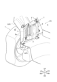
- FIG. 1 is a partially sectional perspective view, seen from the rear, of a luggage compartment of a vehicle provided with a cooling structure according to a first embodiment of the present invention.
- FIG. 2 is a perspective view of the cooling structure including an electronic unit and a cover according to the first embodiment.
- FIG. 3 is an exploded perspective view of FIG.
- FIG. 4 is a perspective view of the electronic unit of FIG. 2 with the cover removed.
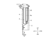
- FIG. 5 is a cross-sectional view of the cooling structure of FIG. 2 taken along a vertical plane passing through the opening of the cover of the electronic unit, as viewed from the front of the vehicle.
- FIG. 6 is a cross-sectional view of the cooling structure of FIG.
- FIG. 7 is a cross-sectional view of the cooling structure of FIG. 2 taken along a vertical plane passing through the first wall portion of the cover, as viewed from the right side of the vehicle.
- FIG. 8 is a cross-sectional view of the cooling structure of FIG. 1 taken along a vertical plane passing through a position on the vehicle rear side relative to the bracket, as viewed from the rear of the vehicle.
- FIG. 9 is a cross-sectional view of the cooling structure of FIG. 1 taken along a vertical plane passing through the opening of the case of the electronic unit, as viewed from the rear of the vehicle.
- 10A is a side view of the cooling structure of FIG.
- FIG. 10B is a side view of the cooling structure according to the other embodiment, as viewed from the right side of the vehicle.
- FIG. 11 is a partially sectional perspective view of a luggage compartment of a vehicle provided with a cooling structure according to a second embodiment of the present invention, as viewed from the rear of the vehicle.
- 12A is a cross-sectional view of the cooling structure of FIG. 11 taken along a horizontal plane passing through an opening of a case of an electronic unit, as viewed from above the vehicle.
- FIG. 12B is a cross-sectional view taken along line XIIB-XIIB of FIG. 12A.
- FIG. 13 is a side view of a cooling structure including an electronic unit, a cover, and a duct according to the second embodiment, as viewed from the right side of the vehicle.
- FIG. 14 is a partially sectional perspective view of a luggage compartment of a vehicle provided with a cooling structure according to a modified example of the second embodiment, as viewed from the rear of the vehicle.
- the front of the vehicle is indicated as FR, the rear of the vehicle as RR, the right side of the vehicle as RH, the left side of the vehicle as LH, the top of the vehicle as UP, and the bottom of the vehicle as DN.
- the terms front, rear, right, left, top, and bottom refer to the above-mentioned directions of the vehicle unless otherwise specified.
- the side trim 71 is omitted so that the electronic unit 2, cover 3, etc. can be easily seen.
- the harness H is omitted.
- the cooling structure 1 includes an assembly 9 of an electronic unit 2 and a cover 3, and is provided at the rear of the vehicle, more specifically, in the luggage compartment LG of the vehicle.
- the electronic unit 2 of this embodiment is a DC-AC inverter that converts DC power from a high-voltage battery mounted on the vehicle into AC power (100V in Japan, 120V in North America, and 220V in Europe, China, etc.) for use in home appliances. That is, the electronic unit 2 switches, and thus generates heat loss. For this reason, the electronic unit 2 needs to be cooled.
- the luggage space LG is the space formed behind the rear seat S, and if the rear seat S is foldable, it also includes the space created by folding it down. As shown in Figures 1, 8, and 9, the luggage space LG includes a wheel house 5 for the left rear tire T, a floor panel 6, and a side trim 71, which is an interior trim piece located on the inside of the vehicle compartment (towards the center of the vehicle in the vehicle width direction) relative to the wheel house 5.
- the wheel house 5 and floor panel 6 are also referred to as vehicle body panels P.
- the wheel house 5 is a part of the metallic side panel of the vehicle, and houses the rear tire T on the left side of the vehicle outside the passenger compartment. As shown in Figs. 1, 8, and 9, the wheel house 5 has an inner wall surface 5a, which is the surface on the passenger compartment side that extends in the front-rear and up-down directions, and an inclined surface 5b that extends integrally from the upper edge of the inner wall surface 5a toward the upper left. A sub-bracket 50 for fixing the bracket 4 is welded to the lower part of the inclined surface 5b.
- the wheel house 5 is made of metal, but the material is not particularly limited, and it may be made of resin or fiber-reinforced resin, for example.
- the assembly 9 is mounted on the left wheel house 5 side in this embodiment, it may be mounted on the right wheel house 5 side. In this case, the configuration of the cooling structure 1 according to this embodiment may be reversed left and right.
- the floor panel 6 is a metal plate having a surface extending in the front-rear and left-right directions, and forms the floor surface of the luggage compartment LG.
- a floor trim 72 which is an interior trim connected to the lower edge of the side trim 71, is provided on the upper surface of the floor panel 6.
- the left edge of the floor panel 6 is fixed to the lower part of the inner wall surface 5a of the wheel house 5 by bolts, welding, etc.
- Two bolt holes are provided on the left end of the floor panel 6 for fixing two lower extensions 41 of the bracket 4 described below with bolts BT and nuts NT.
- the floor panel 6 is made of metal, but the material is not particularly limited and may be made of resin or fiber-reinforced resin, for example.
- An assembly 9 is fixed to the wheel house 5 and floor panel 6 via brackets 4.
- the assembly 9 is arranged so that its surface is aligned along the inner wall surface 5a of the wheel house 5, rather than along the floor panel 6, in order to improve the storage capacity of the luggage compartment LG.
- the side trim 71 is a resin plate having a surface extending in the front-rear and up-down directions (a surface along the inner wall surface 5a of the wheel house 5) and a surface along the inclined surface 5b of the wheel house 5.
- the lower part of the side trim 71 extends to the floor panel 6, and the upper part extends to the ceiling of the vehicle.
- the side trim 71 is disposed on the passenger compartment side of the wheel house 5, bracket 4, electronic unit 2, and cover 3.
- the bracket 4 and assembly 9 are disposed in the space SP surrounded by the side trim 71, wheel house 5, and floor panel 6.
- the side trim 71 is disposed covering the assembly 9 on the side opposite the wheel house 5 of the assembly 9. As shown in FIG.
- the side trim 71 has a plurality of slit-shaped air vents 71a in the intake area SE near the intake port 33 of the cover 3 described below, which connect the space on the wheel house 5 side to the space on the passenger compartment side.
- the side trim 71 is made of resin, but the material is not particularly limited and may be made of, for example, metal or fiber-reinforced resin.
- the shape and number of the ventilation holes 71a are also not limited to the above, and for example, the shape may be circular and there may be only one.
- the bracket 4 is a member for fixing the assembly 9 to the luggage compartment LG, and is fixed to the wheel house 5 and floor panel 6 (body panel P) as shown in FIG. 1.
- the bracket 4 is formed into a substantially flat plate shape by press-molding a high-tensile steel plate.
- the bracket 4 has a central plate-shaped portion 40, side extensions 41, a lower extension 41, a sub-extension 42, and a fixing portion 43.
- the central plate-shaped portion 40 has a surface that extends in the front-rear and up-down directions.
- the upper extension 41 extends integrally from the upper left and right corners of the central plate-shaped portion 40.
- the central plate-shaped portion 40 has a plurality of beads 40a extending in the front-rear direction, and a flange is formed on the periphery of the central plate-shaped portion 40.
- the beads 40a and the flange contribute to improving the strength and rigidity of the central plate-shaped portion 40.
- the upper extension portion 41 is a fixing portion for fixing the bracket 4 to the sub-bracket 50, and is also a fixing portion to which the cover 3 is fixed.
- the lower extension portion 41 is a fixing portion for fixing the bracket 4 to the floor panel 6.
- the sub-extension portion 42 is a fixing portion for fixing the bracket 4 to the inner wall surface 5a of the wheel house 5.
- the fixing portion 43 is a fixing portion for fixing the cover 3.
- Each extension portion 41, sub-extension portion 42, and fixing portion 43 has a bolt hole for fixing.
- the bracket 4 is made of metal, but the material is not particularly limited, and may be made of resin or fiber-reinforced resin, for example.
- the electronic unit 2 is an inverter. As shown in Figs. 1 to 3, the electronic unit 2 is fixed to the cover 3 and fixed to the bracket 4 via the cover 3.
- the electronic unit 2 includes a case 20, electronic components 23, cooling fins 24, a blower fan 25, and a harness terminal (harness connection portion) 26.
- the electronic components 23 and cooling fins 24 are shown in Fig. 5, but are omitted in Figs. 6, 9, and 12A.
- the electronic components 23 are driven by electricity supplied through the harness terminals 26 and generate heat.
- the cooling fins 24 take in the heat generated by the electronic components 23 and dissipate it into the air.
- the blower fan 25 includes a fan and a drive source such as a motor that rotates the fan.
- the blower fan 25 generates an airflow by rotating the fan to cool the cooling fins 24.
- the drive source is driven by electricity supplied through the harness terminals 26.
- the case 20 has a box shape and houses the electronic components 23, the cooling fins 24, and the blower fan 25 inside. Note that the electronic unit 2 may not include the cooling fins 24, and may be configured to directly cool the electronic components 23 with the airflow from the blower fan 25.
- the case 20 of the electronic unit 2 has a surface 20a facing to the right, a back surface 20b facing to the left, an upper surface 20c facing upward, a lower surface 20d facing downward, a front surface 20e facing forward, and a rear surface 20f facing rearward.
- the electronic unit 2 is arranged with the surface 20a of the case 20 aligned along the surface of the side trim 71, and the back surface 20b of the case 20 aligned along the inner wall surface 5a of the wheel house 5.
- the back surface 20b of the case 20 is spaced apart from the central plate-shaped portion 40 of the bracket 4.
- the thickness direction generally means a direction perpendicular to the spreading direction of a flat object, and in this embodiment, the direction perpendicular to the surface 20a and back surface 20b of the case 20 is the thickness direction of the electronic unit 2 (case 20).
- the thickness direction of the electronic unit 2 and the thickness direction of the assembly 9 coincide with each other.
- the case 20 does not have to be strictly rectangular, but may have any shape that has mutually orthogonal or nearly orthogonal surfaces in which the opening 21 and exhaust port 22 described below can be provided.
- an opening 21 that opens to the right is provided at approximately the center of the surface 20a of the case 20.
- the opening 21 is provided on the surface 20a, which is the side of the case 20 opposite the wheel house 5 and bracket 4.
- the opening 21 is an opening for drawing air from the outside of the case 20 into the inside of the case 20 by the blower fan 25 (taking in air for cooling).
- Bolt holes for fixing the cover 3 are provided at the four corners of the surface 20a of the case 20.
- the opening 21 is circular in shape and located approximately in the center, but is not limited to this and can have any shape and be located in any position.
- the rear surface 20f of the case 20 is provided with an exhaust port 22 that opens rearward, more specifically, toward the rear of the wheel house 5.
- the exhaust port 22 is an opening for discharging air drawn into the case 20 from the opening 21 by the blower fan 25 to the outside of the case 20.
- the shape of the exhaust port 22 is rectangular, but is not limited to this and can be any shape.
- Two harness terminals 26 protrude downward from the underside 20d of the case 20, forming a harness connection portion. As shown in FIG. 10A, the harness terminals 26 are connected to a harness H extending from a high-voltage battery mounted on the vehicle.
- the cover 3 is formed by press-molding a high-tensile steel plate.
- the press-molded steel plate is fixed at several points with rivets RT to form the cover 3 into a box shape.
- the electronic unit 2 is attached to the cover 3.
- the cover 3 is fixed to the bracket 4 on the inside of the passenger compartment relative to the wheel house 5 with the electronic unit 2 attached.
- the electronic unit 2 is housed in the space formed by the cover 3 and the bracket 4.
- the cover 3 has a main body 30 that has a surface extending in the front-rear and up-down directions and faces the surface 20a of the case 20.
- the lower end of the main body 30 is located lower than the lower end of the case 20 and higher than the lower end of the bracket 4.
- the main body 30 has a first surface 30a, a second surface 30b located to the left of the first surface 30a (towards the case 20), and a third surface 30c located to the left of the second surface 30b.
- the main body 30 also has a first wall 30d that connects the first surface 30a to the second surface 30b and the third surface 30c, and a second wall 30e that connects the second surface 30b to the third surface 30c.
- the first surface 30a is a surface larger than the opening 21 of the case 20, and is provided facing the opening 21 so as to cover the entire opening 21.
- the first surface 30a also extends from the upper vicinity of the opening 21 downward from the lower end of the surface 20a of the case 20.
- the first wall portion 30d is provided integrally with the first surface 30a so as to surround the three peripheries of the rear, upper, and front of the first surface 30a, and extends leftward from the first surface 30a.
- the lower portion of the first surface 30a and the first wall portion 30d opens downward, forming an intake port 33 for drawing air from the outside of the case 20 and the cover 3.
- the first surface 30a and the first wall portion 30d form an intake flow path 34 between the surface 20a of the case 20 and the first wall portion 30d, which connects the intake port 33 and the opening 21.
- the opening 21 of the electronic unit 2 is located within the intake flow path 34.
- the air intake 33 opens into the space SP between the wheel house 5, floor panel 6, and side trim 71.
- the area near the air intake 33 is an intake area SE for drawing in air to be used for cooling electronic components.
- the second surface 30b has a plurality of through holes 36 above the opening 21 and the first surface 30a, that is, in a portion of the cover 3 facing the upper end surface where the intake passage 34 of the case 20 is not provided.
- the plurality of through holes 36 allow air to circulate between the space between the case 20 and the cover 3 and the external space. For example, hot air trapped in the space between the case 20 and the cover 3 is exhausted to the external space through the plurality of through holes 36. Depending on the conditions, air flows from the outside into the space between the case 20 and the cover 3 through the plurality of through holes 36. In this case, the air that flows in is sucked in through the opening 21 and exhausted from the exhaust port 22.
- the shape and number of the through holes 36 are not limited to the above, and for example, the shape may be a slit shape, and the number may be one. By providing the through holes 36 so that they open in the left-right direction instead of the up-down direction, it is possible to prevent foreign matter such as moisture from entering the inside of the assembly 9 through the through holes 36.
- the third surface 30c has bolt holes BH for fixing the case 20 to the cover 3 at positions corresponding to the bolt holes BH of the case 20.
- the cover 3 has an upper surface portion 31a extending integrally to the left from the upper edges of the second surface 30b and the third surface 30c, a front surface portion 31b extending integrally to the left from the front edge of the front third surface 30c, and a rear surface portion 31c extending integrally to the left from the rear edge of the rear third surface 30c.
- the lower surface of the cover 3 is open downward and serves as an intake port 33.
- the cover 3 also has an extension portion 32 extending integrally upward from the upper edge of the front surface portion 31b and an extension portion 32 extending integrally forward from the lower edge of the front surface portion 31b.
- the cover 3 has an extension portion 32 extending integrally rearward from the rear edge of the upper surface portion 31a and an extension portion 32 extending integrally rearward from the lower edge of the rear surface portion 31c.
- Each extension portion 32 of the cover 3 has a bolt hole BH for fixing the cover 3 to the bracket 4.
- the upper surface portion 31a of the cover 3 covers the upper surface 20c of the case 20.
- the front surface portion 31b of the cover 3 covers the front surface 20e of the case 20, and extends below the lower end of the case 20.
- the lower end of the front surface portion 31b is located above the lower end of the bracket 4.
- the rear surface portion 31c of the cover 3 covers the rear surface 20f of the case 20 from a position below the exhaust port 22 on the rear surface 20f of the case 20, and extends below the lower end of the case 20.
- the lower end of the rear surface portion 31c is located above the lower end of the bracket 4.
- the cover 3 has a rear opening 35 above the rear surface portion 31c for exposing the exhaust port 22.
- the three end faces of the surface 20a of the case 20 and the cover 3 do not need to be completely sealed, and some air leakage is permitted. In other words, it is sufficient that air is drawn into the intake flow path 34 mainly through the intake port 33.
- the location that blocks or impedes to a certain degree the flow of air between the intake flow path 34 and the external space may be two end faces or one end face of the surface 20a of the case 20.
- the portion of the surface 20a having the opening 21 of the case 20 where the intake passage 34 is provided and the first surface 30a of the cover 3 are separated by a separation distance (first separation distance) h1 in the left-right direction (vehicle width direction, thickness direction). Also, the end face of the surface 20a having the opening 21 of the case 20 where the intake passage 34 is not provided and the second surface 30b of the cover 3 are separated by a separation distance (second separation distance) h2 in the left-right direction.
- the separation distance (first separation distance) h1 is greater than the separation distance (second separation distance) h2.
- the separation distance (second separation distance) in the left-right direction between the 20a of the case 20 and the third surface 30c of the cover 3, which is the attachment point between the case 20 and the cover 3, is zero.
- the width of the intake passage 34 in the front-rear direction is greater than the width of the opening 21 in the front-rear direction.
- the cross-sectional area of the exhaust port 22 shown in FIG. 8 is equal to or greater than the cross-sectional area of the intake flow path.
- the cross-sectional shape of the intake flow path 34 is rectangular, but this is not limited to this and may be any shape.
- the effective cross-sectional area of the exhaust port 22 may be configured to be equal to or greater than the effective cross-sectional area of the intake flow path.
- the air intake 33 of the cover 3 opens in the same direction as the harness connection port 27 that opens downward to allow access to the harness terminal 26.
- the position of the air intake 33 and the position of the harness connection port 27 can be made to coincide.
- the air intake 33 is provided to open forward, which is a direction different from the opening direction of the harness connection port 27, and the position of the air intake 33 and the position of the harness connection port 27 do not coincide.
- the area required for the layout of the assembly 9 is larger than that of the cooling structure 1 according to the first embodiment by the part of the air intake 33 or the part of the harness connection port 27.
- the cooling structure 1 according to the first embodiment can reduce the area required for the layout of the assembly 9 compared to the cooling structure 1A according to the comparative embodiment.
- the assembly 9 is arranged with the rear surface 20b of the electronic unit 2 aligned along the inner wall surface 5a of the wheel house 5, and the main body 30 of the cover 3 aligned along the surface of the side trim 71.
- the assembly 9 is arranged in the narrow space between the wheel house 5 and the side trim 71.
- the air taken into the intake flow path 34 passes through the opening 21 and hits the cooling fin 24, and the heated air (heated air) is exhausted from the exhaust port 22.
- the heated air exhausted from the exhaust port 22 is discharged toward the space behind the vehicle between the rear of the wheel house 5 and the side trim 71. Because the space behind the vehicle is wide and there is nothing blocking the flow, the exhausted heated air flows toward the rear and is efficiently diffused in the rear space, dissipating heat. In addition, because the rear, upper, and front spaces of the wheel house 5 are interconnected, the exhausted heated air also diffuses into these upper and front spaces. For this reason, the heated air exhausted from the exhaust port 22 is less likely to be sucked in through the intake port 33. In addition, the heat of the heated air exhausted from the exhaust port 22 is also less likely to be transferred to the air in the intake area SE.
- the bracket 4 is placed in the luggage compartment LG of the vehicle, and the bolts BT inserted into the bolt holes BH are fastened with the nuts NT to secure the two lower extensions 41 of the bracket 4 to the left end of the floor panel 6, which has two bolt holes. With the bracket 4 fixed to the floor panel 6, the two upper extensions 41 of the bracket 4 are aligned with the sub-bracket 50.
- the electronic unit 2 is fixed to the cover 3. Specifically, with the bolt holes BH provided at the four corners of the surface 20a of the case 20 of the electronic unit 2 aligned with the bolt holes BH provided in the third surface 30c of the cover 3, the bolts BT are inserted into the bolt holes BH of the cover 3 and screwed into the bolt holes BH of the case 20.
- the cover 3 with the electronic unit 2 fixed thereto is attached to the bracket 4.
- the extension portion 32 of the cover 3 is fixed to the corresponding extension portion 41, sub-extension portion 42, and fixing portion 43 of the bracket 4 by fastening the bolt BT inserted into the bolt hole BH and the nut NT.
- the electronic unit 2, cover 3, and bracket 4 of the cooling structure 1 are assembled and attached to the vehicle body panel P.
- the assembly 9 is attached to the wheel house 5 and the floor panel 6 with one surface in the thickness direction positioned along the inner wall surface 5a of the wheel house 5, which is a side panel of the vehicle.
- the fixing method is not limited to the above.
- the number and positions of the bolts BT, nuts NT, and bolt holes BH are not limited to the above.
- fixing methods using welding, adhesives, screws, fitting, etc. may be used instead of the fastening and fixing method using the bolts BT, nuts NT, and bolt holes BH.
- fixing methods using welding, adhesives, screws, fitting, etc. may be used.
- the shape, position, number, etc. of each fixing part for fixing each member are also not limited to the above.
- the order in which each member is fixed is not limited to the above.
- the assembly 9 of the electronic unit 2 and the cover 3 is disposed in such a manner that the surface in the thickness direction is aligned with the inner wall surface 5a of the wheel house 5, which is a vehicle body panel.
- the intake port 33 is opened downward, the intake flow path 34 is provided in the left-right direction (vehicle width direction), and the exhaust flow path is not provided in the left-right direction, but the exhaust port 22 is provided to open rearward. Therefore, the space existing in the exhaust direction of the exhaust port 22 can be effectively utilized as an exhaust flow path, and it is not necessary to provide an exhaust flow path in the thickness direction of the electronic unit 2, so that the size in the thickness direction of the assembly 9 can be suppressed.
- the assembly 9 in a narrow space where the thickness direction and the intake port space are limited.
- the intake port 33 and the exhaust port 22 are opened in different directions in the thickness direction. Therefore, the heated air exhausted from the exhaust port 22 flows and diffuses in a direction different from the installation position of the intake port 33, and is less likely to be sucked in again from the intake port 33. Therefore, even in a narrow space where the thickness direction is limited, efficient cooling of the electronic unit 2 is possible.
- the flow path cross-sectional area (or effective cross-sectional area) of the space of the vehicle to which the heated air exhausted from the exhaust port 22 is exhausted is larger than the flow path cross-sectional area (or effective cross-sectional area) of the intake flow path 34. Therefore, pressure loss is unlikely to occur in the flow of air from the air intake port 33 through the intake flow path 34 and the exhaust port 22 to the space of the vehicle to be exhausted, and there is no need to increase the output of the blower fan 25. Therefore, the electronic unit 2 that requires cooling can be arranged in a limited space (for example, the luggage compartment LG of the vehicle) with good space efficiency, and a duct can be laid out as necessary.
- the flow path cross-sectional area (or effective cross-sectional area) of the space of the vehicle to which the heated air is exhausted is larger than the flow path cross-sectional area (or effective cross-sectional area) of the intake flow path 34, there is no need to seal the intake flow path 34. Therefore, a structure for sealing the intake flow path 34 is not required, and it is possible to suppress an increase in the manufacturing cost of the member, an increase in the cost and weight due to an increase in parts, etc.
- the cover 3 is provided in a position facing the opening 21 of the electronic unit 2. This ensures that the distance between the opening 21 and other components is kept constant, allowing air to be drawn in efficiently. Furthermore, providing the cover 3 on the electronic unit 2 can provide the function of protecting the electronic unit 2, either alone or together with the bracket 4, against interference during a rear-end collision, etc.
- the distance h1 in the thickness direction between the cover 3 and the portion of the surface 20a having the opening 21 of the case 20 where the intake flow path 34 is provided is greater than the distance h2 in the thickness direction between the cover 3 and the end face of the surface 20a having the opening 21 of the case 20 where the intake flow path 34 is not provided. This reduces pressure loss, making it easier for air to flow toward the opening 21.
- the intake flow path 34 can be easily provided without providing a sealing part on the end face side of the case 20. Since the intake flow path 34 sucks in air using the blower fan 25, some air leakage is permitted, unlike a flow path that requires waterproofing.
- the end faces of the surface 20a having the opening 21 of the case 20 where the intake flow path 34 is not provided are the three end faces located on three sides of the opening 21. This makes it difficult for the exhausted heated air to be drawn into the intake passage 34 from the three end faces.
- the assembly 9 is installed on the side panel of the luggage compartment LG of the vehicle (more specifically, the wheel house 5).
- the exhaust port 22 opens toward the rear of the vehicle, and the intake port 33 opens toward the bottom of the vehicle. Therefore, a wide space SP is provided between the side panel of the luggage compartment LG and the side trim 71, particularly toward the rear, upper, and front of the vehicle, so that a sufficient space can be secured to diffuse the heated air exhausted from the exhaust port 22.
- the electronic unit 2 vertically between the side panel of the luggage compartment LG and the side trim 71, the storage capacity of the luggage compartment LG can be improved.
- the electronic unit 2 is an inverter that provides a household power source, arranging the electronic unit 2 in the luggage compartment LG makes it easier for the user to access it.
- a number of circular through holes 36 are provided in the cover 3 above the opening 21 of the case 20. This makes it easier to exhaust hot air trapped between the case 20 and the cover 3 to the outside through the multiple through holes 36 provided above the cover 3. Depending on the conditions, air may flow from the outside into the space between the case 20 and the cover 3 through the multiple through holes 36. In this case, the air that has flowed in is sucked in through the opening 21 and exhausted from the exhaust port 22. Therefore, even in this case, it is easier to exhaust hot air trapped between the case 20 and the cover 3 to the outside.
- the assembly 9 is installed on the side panel of the luggage compartment LG of the vehicle (more specifically, the wheel house 5), and the opening direction of the intake port 33 is downward.
- a harness connection port 27 is provided that is accessible to the harness connection terminal (harness connection portion) 26 provided below the case 20 and opens in the same direction as the intake port 33. Therefore, compared to a case in which the intake port 33 and the harness connection port 27 face in different directions (comparative embodiment), the area required for the layout of the assembly 9 can be reduced.
- the harness connection portion can be protected from obstructions during a rear-end collision, etc.
- a side trim 71 is provided to cover the assembly 9 on the side opposite to the side panel (more specifically, the wheel house 5).
- an air vent 71a is provided near the air intake 33 of the side trim 71.
- the air vent 71a makes it easier to take in unheated air from the vehicle cabin into the air intake area SE, and the temperature of the air taken in from the air intake 33 can be lowered.
- the side trim 71 is made of a resin material, there is a possibility that heat will be trapped significantly, so providing the air vent 71a in the side trim 71 is more effective.
- the air intake flow path 34 is provided on the side trim 71 side of the assembly 9 in the thickness direction. For this reason, the air intake 33 can be disposed near the air vent 71a of the side trim 71, and it is easier to take in unheated air from the vehicle cabin into the air intake area SE from the air vent 71a.
- the assembly 9 is installed in the wheel house 5 of the luggage compartment LG of the vehicle.
- the wheel house 5 of the luggage compartment LG and the side trim 71, there is a wide space SP that is connected to the rear, upper, and front of the vehicle. Therefore, the heated air exhausted from the exhaust port 22 diffuses into the space behind, above, and in front of the wheel house 5. Therefore, a sufficient space can be secured to diffuse the heated air exhausted from the exhaust port 22.
- a cooling structure 1B for an electronic unit 2 mounted on a vehicle according to a second embodiment will be described with reference to Figures 11 to 13.
- the second embodiment has the same configuration as the first embodiment except for the provision of a duct 8 described below, and therefore the same components are designated by the same reference numerals and will not be described.
- the cooling structure 1B includes a resin duct 8 that extends from the exhaust port 22 of the case 20 of the electronic unit 2 to the rear of the vehicle.
- the duct 8 has a tube shape with a duct connection port 8a at one end communicating with a duct exhaust port 8b at the other end.
- the duct connection port 8a is connected to the exhaust port 22 near the rear opening 35 of the cover 3.
- the duct exhaust port 8b opens into the rear space of the wheel house 5 between the rear of the wheel house 5 and the side trim 71, located rearward of the rear end of the wheel house 5 spaced rearward from the exhaust port 22.
- the duct 8 exhausts the air exhausted from the exhaust port 22 through the duct connection port 8a, through the duct flow path (exhaust flow path), which is the space inside the tube, to the rear space of the wheel house 5 described above.
- the shape of the duct 8 is not limited to a tube, so long as it can exhaust the air exhausted from the exhaust port 22 into a separated space.
- the duct 8 is made of resin, but the material is not particularly limited, and it may be made of, for example, metal or fiber-reinforced resin.
- the connection between the duct connection port 8a and the exhaust port 22 may be completely or partially sealed, so long as it is possible to introduce most of the exhaust air from the exhaust port 22 into the tube.
- a sealing member such as a resin packing may be placed between the duct connection port 8a and the exhaust port 22 to improve the sealing between the duct connection port 8a and the exhaust port 22.
- the flow path cross-sectional area (or effective cross-sectional area) of the duct flow path inside the duct 8 shown in FIG. 12B is larger than the flow path cross-sectional area (or effective cross-sectional area) of the exhaust port 22 shown in FIG. 8 and the flow path cross-sectional area (or effective cross-sectional area) of the intake flow path 34 shown in FIG. 6.
- the flow path cross-sectional area (or effective cross-sectional area) of the duct flow path may be smaller than the flow path cross-sectional area (or effective cross-sectional area) of the exhaust port 22.
- the duct 8 is connected to the exhaust port 22 on the rear side of the assembly 9 and extends rearward. Also, when viewed from the right, the rear end of the case 20 is located forward of the rear end of the bracket 4 and the duct 8.
- the space into which the duct exhaust port 8b opens is not limited to the rear space of the wheel house 5 between the rear of the wheel house 5 and the side trim 71.
- a cooling structure 1C relating to a modified example of the second embodiment will be described.
- the duct exhaust port 8b opens through a hole penetrating the body panel P behind the wheel house 5 into a space that communicates with the vehicle's draft (not shown) for discharging intake air from an air conditioner or the like to the outside of the vehicle.
- the effects of the second embodiment and the modified version of the second embodiment are described below.
- the second embodiment and the modified version of the second embodiment have the same configuration as the first embodiment, except that the location where air is exhausted in the first embodiment (exhaust port 22) is changed to the duct exhaust port 8b of the duct 8. Therefore, the second embodiment and the modified version of the second embodiment can also achieve the effects (1) to (10) of the first embodiment described above.
- a duct 8 is provided that is connected to the exhaust port 22 of the case 20. Therefore, the duct 8 allows the air exhausted from the exhaust port 22 to be exhausted to a space farther away from the intake port 33, and prevents the heated air exhausted from the exhaust port 22 from being sucked in again through the intake port 33.
- the flow path cross-sectional area (or effective cross-sectional area) of the duct 8 is larger than the flow path cross-sectional area (or effective cross-sectional area) of the intake flow path 34. Therefore, pressure loss is small, and exhaust from the intake port 33 to the duct exhaust port 8b can be more promoted. In addition, there is no need to increase the output of the blower fan 25, and there is no need to seal the intake flow path 34.
- the assembly 9 is installed on the body panel of the luggage compartment LG of the vehicle (more specifically, the wheel house 5), the opening direction of the exhaust port 22 is toward the rear of the vehicle, and the duct 8 extends into the rear space of the wheel house 5.
- the air exhausted from the exhaust port 22 can be exhausted into the relatively large rear space of the body panel of the luggage compartment LG, which is separated from the exhaust port 22, and the heated air exhausted from the exhaust port 22 can be efficiently dispersed.
- the opening direction of the exhaust port 22 is toward the rear of the vehicle, the duct 8 extends rearward, the assembly 9 is attached to the vehicle body panel P via the bracket 4, and the rear end of the case 20 of the electronic unit 2 is positioned forward of the rear end of the bracket 4.
- the bracket 4 can suppress interference with the electronic unit 2 from the interfering object, and short-circuiting of the conductive parts of the electronic unit 2 can be reduced. Even if an interfering object does interfere with the electronic unit 2, the interference occurs via the duct 8 and not the electronic component 23, so short-circuiting of the conductive parts of the electronic unit 2 can be reduced.
- the duct exhaust port 8b is opened into the space connected to the draft lid through a hole that penetrates the vehicle body panel. Therefore, the heated air exhausted from the duct exhaust port 8b is discharged into the negative pressure space created by the draft lid. This makes it possible to more reliably prevent the heated air exhausted from the duct exhaust port 8b from being sucked in again through the intake port 33.
- the cooling structure 1 to 1C includes an assembly 9 of an electronic unit 2 and a cover 3, but may further include at least one of a bracket 4, a wheel house 5, a floor panel 6, and a side trim 71.
- the cover has multiple through holes 36, but it is not necessary to provide the through holes 36.
- the side trim 71 is provided with an air vent 71a, but the air vent 71a does not have to be provided. Even if the side trim 71 does not have an air vent 71a, the air exhausted from the exhaust port 22 flows toward the large space at the rear and is diffused, so that the exhausted heated air is not sucked in from the intake port 33.
- the main body 30 of the cover 3 has three surfaces, the first surface 30a to the third surface 30c, which are spaced apart from the surface 20a of the case 20 at different distances, but this is not limited to the above.
- the main body 30 of the cover 3 may have two surfaces spaced apart from the surface 20a of the case 20 at different distances.
- the second surface 30b and the third surface 30c may be formed as one surface having the same distance from the surface 20a of the case 20.
- a plurality of through holes 36 and a plurality of bolt holes BH for fixing may be provided on this one surface.
- the main body 30 of the cover 3 may also have four or more surfaces spaced apart from the surface 20a of the case 20 at different distances. Even with such a configuration, pressure loss can be reduced.
- the width of the intake flow path 34 is set to be equal to or greater than the width of the opening 21, but is not limited to this.
- the width of the intake flow path 34 may be smaller than the width of the opening 21.
- the upper end of the intake flow path 34 is located above the upper end of the opening 21, but is not limited to this.
- the opening 21 is provided on the surface 20a, which is the surface of the case 20 opposite the wheel house 5 and bracket 4.
- the cover 3 faces the surface 20a of the case 20, and forms an intake flow path 34 with the surface 20a.
- the intake flow path 34 is located on the opposite side of the case 20 from the wheel house 5 and bracket 4.
- the intake flow path 34 may be disposed between the case 20 and the wheel house 5 and/or bracket 4.
- the intake port 33 is somewhat farther from the vent 71a of the side trim 71 than in all the above-mentioned embodiments, but unheated air in the vehicle cabin can still be taken into the intake area SE through the vent 71a of the side trim 71.
- the intake port 33 is provided to open below the assembly 9, but is not limited to this.
- the intake port 33 may be provided to open in any direction above, in front of, or behind the assembly 9, so long as the intake port 33 opens in a direction perpendicular to the thickness direction of the assembly 9 that is different from the opening direction of the exhaust port 22.
- the exhaust port 22 is provided only on the rear surface 20f of the case 20, but this is not limited to this.
- the exhaust port 22 may be provided on one or more of the upper surface 20c, lower surface 20d, and front surface 20e of the case 20, so long as the side surface is located in a direction perpendicular to the thickness direction of the case 20 and different from the opening direction of the intake port 33.
- the direction in which the duct 8 extends from the exhaust port 22 is not limited to the rear.
- the duct 8 is arranged to extend in a direction corresponding to the opening direction of the exhaust port 22, rather than to the rear.
- the exhaust port 22 is provided on two or more side surfaces (multiple directions) of the case 20, the duct 8 corresponding to each exhaust port 22 or at least one exhaust port 22 may be connected, and the duct 8 may be extended to a position separated from the exhaust port 22 and the intake port 33.
- the air exhausted from the exhaust port 22 can be exhausted to a space farther away from the intake port 33 of the cover, and the heated air discharged from the exhaust port 22 can be prevented from being sucked in from the intake port 33.
- the electronic unit 2 is an inverter for providing AC power to the user, and is therefore arranged in a position in the luggage compartment LG that is accessible to the user.
- the electronic unit 2 is not limited to an inverter, and may be any unit that includes electronic components 23 that generate heat and requires cooling. In this case, the electronic unit 2 does not need to be arranged in a position that is accessible to the user.
- the assembly 9 is fixed to the vehicle body panel P (wheel house 5 and floor panel 6) via the bracket 4, and the electronic unit 2 is fixed to the bracket 4 via the cover 3, but this is not limited to this.
- the assembly 9 may be fixed directly to the vehicle body panel P.
- the electronic unit 2 may be fixed directly to the bracket 4 without the cover 3.
- the assembly 9 is attached to the wheel house 5, but is not limited thereto.
- the assembly 9 may be attached to a side panel other than the wheel house 5 having a space that extends in at least one direction.
- the assembly 9 is arranged in a posture (vertical placement) in which one side surface in the thickness direction is aligned with the inner wall surface 5a of the wheel house 5, which is the side panel of the vehicle, but is not limited thereto.
- the assembly 9 may be arranged in a posture (flat placement) in which one side surface in the thickness direction is aligned with the surface of the floor panel 6 of the vehicle.
- the assembly 9 is provided in the luggage compartment LG of the vehicle, but is not limited thereto.
- the assembly 9 may be provided in a side panel or floor panel having a space that extends in at least one direction in the passenger compartment.
- 1, 1A, 1B, 1C Cooling structure of electronic unit; 2: Electronic unit; 20: Case; 20a: Surface; 21: Opening; 22: Exhaust port; 23: Electronic components; 25: Blower fan; 26: Harness terminal (harness connection); 27: Harness connection port; 3: Cover; 33: Intake port; 34: Intake flow path; 36: Through hole; 4: Bracket; 5: Wheelhouse (side panel); 71: Side trim (interior trim); 71a: Vent; 8: Duct; 9: Assembly (electronic unit and cover); P: Body panel (wheelhouse, floor panel, side panel); LG: Luggage compartment; h1: First separation distance; h2: Second separation distance
Landscapes
- Engineering & Computer Science (AREA)
- Mechanical Engineering (AREA)
- Chemical & Material Sciences (AREA)
- Combustion & Propulsion (AREA)
- Transportation (AREA)
- Physics & Mathematics (AREA)
- Thermal Sciences (AREA)
- Microelectronics & Electronic Packaging (AREA)
- Cooling, Air Intake And Gas Exhaust, And Fuel Tank Arrangements In Propulsion Units (AREA)
Priority Applications (4)
| Application Number | Priority Date | Filing Date | Title |
|---|---|---|---|
| EP22965105.4A EP4617123A4 (en) | 2022-11-09 | 2022-11-09 | COOLING STRUCTURE OF AN EMBEDDED ELECTRONIC UNIT |
| CN202280101272.3A CN120076951A (zh) | 2022-11-09 | 2022-11-09 | 搭载于车辆的电子单元的冷却构造 |
| PCT/JP2022/041631 WO2024100780A1 (ja) | 2022-11-09 | 2022-11-09 | 車両に搭載される電子ユニットの冷却構造 |
| JP2024556901A JP7779404B2 (ja) | 2022-11-09 | 2022-11-09 | 車両に搭載される電子ユニットの冷却構造 |
Applications Claiming Priority (1)
| Application Number | Priority Date | Filing Date | Title |
|---|---|---|---|
| PCT/JP2022/041631 WO2024100780A1 (ja) | 2022-11-09 | 2022-11-09 | 車両に搭載される電子ユニットの冷却構造 |
Publications (1)
| Publication Number | Publication Date |
|---|---|
| WO2024100780A1 true WO2024100780A1 (ja) | 2024-05-16 |
Family
ID=91032404
Family Applications (1)
| Application Number | Title | Priority Date | Filing Date |
|---|---|---|---|
| PCT/JP2022/041631 Ceased WO2024100780A1 (ja) | 2022-11-09 | 2022-11-09 | 車両に搭載される電子ユニットの冷却構造 |
Country Status (4)
| Country | Link |
|---|---|
| EP (1) | EP4617123A4 (https=) |
| JP (1) | JP7779404B2 (https=) |
| CN (1) | CN120076951A (https=) |
| WO (1) | WO2024100780A1 (https=) |
Citations (6)
| Publication number | Priority date | Publication date | Assignee | Title |
|---|---|---|---|---|
| JPH11354960A (ja) | 1998-06-05 | 1999-12-24 | Yazaki Corp | 電子ユニットボックス |
| JP2003002600A (ja) * | 2001-06-15 | 2003-01-08 | Toyota Industries Corp | 産業車両における制御装置の冷却構造及びカウンタバランス型フォークリフトトラック |
| JP2015095612A (ja) * | 2013-11-14 | 2015-05-18 | シャープ株式会社 | 発熱機器の排熱構造 |
| JP2017091658A (ja) * | 2015-11-04 | 2017-05-25 | トヨタ自動車株式会社 | 車両用電池パック |
| JP2020113889A (ja) * | 2019-01-11 | 2020-07-27 | 株式会社Jvcケンウッド | 放熱構造,電子機器,及び撮像装置 |
| JP2021128925A (ja) * | 2020-02-10 | 2021-09-02 | 三菱自動車工業株式会社 | 車両用電池パック |
Family Cites Families (3)
| Publication number | Priority date | Publication date | Assignee | Title |
|---|---|---|---|---|
| JP5641340B2 (ja) * | 2011-03-04 | 2014-12-17 | スズキ株式会社 | 燃料電池車両の吸気装置 |
| JP5983054B2 (ja) * | 2012-06-04 | 2016-08-31 | スズキ株式会社 | ハイブリッド自動車のバッテリパック冷却構造 |
| JP5942611B2 (ja) * | 2012-06-05 | 2016-06-29 | スズキ株式会社 | 電気自動車のバッテリパック冷却構造 |
-
2022
- 2022-11-09 WO PCT/JP2022/041631 patent/WO2024100780A1/ja not_active Ceased
- 2022-11-09 EP EP22965105.4A patent/EP4617123A4/en active Pending
- 2022-11-09 CN CN202280101272.3A patent/CN120076951A/zh active Pending
- 2022-11-09 JP JP2024556901A patent/JP7779404B2/ja active Active
Patent Citations (6)
| Publication number | Priority date | Publication date | Assignee | Title |
|---|---|---|---|---|
| JPH11354960A (ja) | 1998-06-05 | 1999-12-24 | Yazaki Corp | 電子ユニットボックス |
| JP2003002600A (ja) * | 2001-06-15 | 2003-01-08 | Toyota Industries Corp | 産業車両における制御装置の冷却構造及びカウンタバランス型フォークリフトトラック |
| JP2015095612A (ja) * | 2013-11-14 | 2015-05-18 | シャープ株式会社 | 発熱機器の排熱構造 |
| JP2017091658A (ja) * | 2015-11-04 | 2017-05-25 | トヨタ自動車株式会社 | 車両用電池パック |
| JP2020113889A (ja) * | 2019-01-11 | 2020-07-27 | 株式会社Jvcケンウッド | 放熱構造,電子機器,及び撮像装置 |
| JP2021128925A (ja) * | 2020-02-10 | 2021-09-02 | 三菱自動車工業株式会社 | 車両用電池パック |
Non-Patent Citations (1)
| Title |
|---|
| See also references of EP4617123A1 |
Also Published As
| Publication number | Publication date |
|---|---|
| EP4617123A1 (en) | 2025-09-17 |
| CN120076951A (zh) | 2025-05-30 |
| JPWO2024100780A1 (https=) | 2024-05-16 |
| JP7779404B2 (ja) | 2025-12-03 |
| EP4617123A4 (en) | 2026-01-14 |
Similar Documents
| Publication | Publication Date | Title |
|---|---|---|
| JP4361438B2 (ja) | バッテリ冷却システム | |
| CN107074166B (zh) | 车辆 | |
| US20180345759A1 (en) | Vehicle | |
| US20100182750A1 (en) | Industrial vehicle with electric component unit | |
| EP2982544B1 (en) | Structure for installing heat generating electric component in automobile | |
| JP6535570B2 (ja) | 車両 | |
| US7303042B2 (en) | Disposition structure of engine functional components for vehicle | |
| US8763735B2 (en) | Cooling system for electric vehicle and cooling method for electrical component | |
| JP3756435B2 (ja) | 自動車の高圧電装冷却装置 | |
| CN115214332B (zh) | 电动车辆 | |
| JP7815006B2 (ja) | バッテリユニット | |
| JP7346048B2 (ja) | 車両用空調装置 | |
| JP2020172225A (ja) | 車両用電気装置の冷却構造 | |
| JP7115570B2 (ja) | 車両の電池冷却構造 | |
| JP2000275372A (ja) | 空気調和機の室外ユニット | |
| JP6546770B2 (ja) | バッテリの冷却構造 | |
| JP7779404B2 (ja) | 車両に搭載される電子ユニットの冷却構造 | |
| US20230318085A1 (en) | Battery unit | |
| JP6879815B2 (ja) | 車載用バッテリー | |
| JP3082660B2 (ja) | クーラーコンデンサの熱風排出構造 | |
| JP4004930B2 (ja) | 蓄電装置の冷却装置 | |
| JP5099708B2 (ja) | 車載発熱部品への冷却風取入部構造 | |
| JP7576111B2 (ja) | ダクト構造 | |
| CN114619980A (zh) | 车辆下部罩构造 | |
| JP3284849B2 (ja) | 電気自動車のバッテリ格納部構造 |
Legal Events
| Date | Code | Title | Description |
|---|---|---|---|
| 121 | Ep: the epo has been informed by wipo that ep was designated in this application |
Ref document number: 22965105 Country of ref document: EP Kind code of ref document: A1 |
|
| WWE | Wipo information: entry into national phase |
Ref document number: 2024556901 Country of ref document: JP |
|
| WWE | Wipo information: entry into national phase |
Ref document number: 202280101272.3 Country of ref document: CN |
|
| WWP | Wipo information: published in national office |
Ref document number: 202280101272.3 Country of ref document: CN |
|
| WWE | Wipo information: entry into national phase |
Ref document number: 2022965105 Country of ref document: EP |
|
| NENP | Non-entry into the national phase |
Ref country code: DE |
|
| ENP | Entry into the national phase |
Ref document number: 2022965105 Country of ref document: EP Effective date: 20250610 |
|
| WWP | Wipo information: published in national office |
Ref document number: 2022965105 Country of ref document: EP |