WO2024100712A1 - 撮像ユニットの温度を管理する装置、制御装置、方法、及びコンピュータプログラム - Google Patents
撮像ユニットの温度を管理する装置、制御装置、方法、及びコンピュータプログラム Download PDFInfo
- Publication number
- WO2024100712A1 WO2024100712A1 PCT/JP2022/041368 JP2022041368W WO2024100712A1 WO 2024100712 A1 WO2024100712 A1 WO 2024100712A1 JP 2022041368 W JP2022041368 W JP 2022041368W WO 2024100712 A1 WO2024100712 A1 WO 2024100712A1
- Authority
- WO
- WIPO (PCT)
- Prior art keywords
- temperature
- unit
- processor
- detection operation
- detection
- Prior art date
- Legal status (The legal status is an assumption and is not a legal conclusion. Google has not performed a legal analysis and makes no representation as to the accuracy of the status listed.)
- Ceased
Links
Images








Classifications
-
- B—PERFORMING OPERATIONS; TRANSPORTING
- B25—HAND TOOLS; PORTABLE POWER-DRIVEN TOOLS; MANIPULATORS
- B25J—MANIPULATORS; CHAMBERS PROVIDED WITH MANIPULATION DEVICES
- B25J19/00—Accessories fitted to manipulators, e.g. for monitoring, for viewing; Safety devices combined with or specially adapted for use in connection with manipulators
- B25J19/0054—Cooling means
-
- G—PHYSICS
- G05—CONTROLLING; REGULATING
- G05B—CONTROL OR REGULATING SYSTEMS IN GENERAL; FUNCTIONAL ELEMENTS OF SUCH SYSTEMS; MONITORING OR TESTING ARRANGEMENTS FOR SUCH SYSTEMS OR ELEMENTS
- G05B19/00—Program-control systems
- G05B19/02—Program-control systems electric
- G05B19/04—Program control other than numerical control, i.e. in sequence controllers or logic controllers
- G05B19/042—Program control other than numerical control, i.e. in sequence controllers or logic controllers using digital processors
- G05B19/0423—Input/output
- G05B19/0425—Safety, monitoring
-
- B—PERFORMING OPERATIONS; TRANSPORTING
- B25—HAND TOOLS; PORTABLE POWER-DRIVEN TOOLS; MANIPULATORS
- B25J—MANIPULATORS; CHAMBERS PROVIDED WITH MANIPULATION DEVICES
- B25J19/00—Accessories fitted to manipulators, e.g. for monitoring, for viewing; Safety devices combined with or specially adapted for use in connection with manipulators
- B25J19/02—Sensing devices
- B25J19/021—Optical sensing devices
- B25J19/023—Optical sensing devices including video camera means
-
- B—PERFORMING OPERATIONS; TRANSPORTING
- B25—HAND TOOLS; PORTABLE POWER-DRIVEN TOOLS; MANIPULATORS
- B25J—MANIPULATORS; CHAMBERS PROVIDED WITH MANIPULATION DEVICES
- B25J9/00—Program-controlled manipulators
- B25J9/16—Program controls
- B25J9/1674—Program controls characterised by safety, monitoring, diagnostic
-
- H—ELECTRICITY
- H04—ELECTRIC COMMUNICATION TECHNIQUE
- H04N—PICTORIAL COMMUNICATION, e.g. TELEVISION
- H04N23/00—Cameras or camera modules comprising electronic image sensors; Control thereof
- H04N23/50—Constructional details
- H04N23/52—Elements optimising image sensor operation, e.g. for electromagnetic interference [EMI] protection or temperature control by heat transfer or cooling elements
-
- H—ELECTRICITY
- H04—ELECTRIC COMMUNICATION TECHNIQUE
- H04N—PICTORIAL COMMUNICATION, e.g. TELEVISION
- H04N17/00—Diagnosis, testing or measuring for television systems or their details
- H04N17/002—Diagnosis, testing or measuring for television systems or their details for television cameras
-
- H—ELECTRICITY
- H04—ELECTRIC COMMUNICATION TECHNIQUE
- H04N—PICTORIAL COMMUNICATION, e.g. TELEVISION
- H04N23/00—Cameras or camera modules comprising electronic image sensors; Control thereof
- H04N23/50—Constructional details
- H04N23/555—Constructional details for picking-up images in sites, inaccessible due to their dimensions or hazardous conditions, e.g. endoscopes or borescopes
Definitions
- This disclosure relates to an apparatus, a control device, a method, and a computer program for managing the temperature of an imaging unit of an industrial machine.
- Patent Document 1 A technique for adjusting the interval at which an imaging device performs an imaging operation depending on the temperature of the imaging device (for example, Patent Document 1).
- a device for managing the temperature of the imaging unit includes a temperature acquisition unit that acquires a temperature measured by a temperature sensor, a temperature determination unit that determines whether the temperature acquired by the temperature acquisition unit when performing a detection operation for work is within a predetermined tolerance range to ensure the accuracy of the detection operation, and a temperature adjustment unit that executes a warm-up operation to increase the temperature if the temperature determination unit determines that the temperature is lower than the lower limit of the tolerance range, and executes a cooling operation to decrease the temperature if the temperature determination unit determines that the temperature is higher than the upper limit of the tolerance range.
- FIG. 1 is a schematic diagram of an industrial machine according to an embodiment
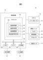
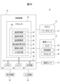
- FIG. 2 is a block diagram of the industrial machine shown in FIG. 1 .
- FIG. 2 is an enlarged view of the imaging unit shown in FIG. 1 .
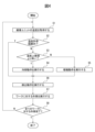
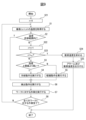
- 2 is a flowchart showing an example of an operation flow of the industrial machine shown in FIG. 1 .
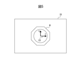
- 4 shows an example of image data of a workpiece captured by an imaging unit.
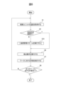
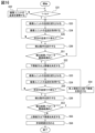
- 10 is a flowchart showing another example of the operation flow of the industrial machine shown in FIG. 1 .
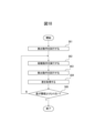
- 7 is a flowchart showing an example of the process of step S10 in FIG. 6.
- FIG. 2 is a block diagram showing other functions of the industrial machine shown in FIG. 1 .
- 9 is a flowchart showing an example of an operation flow of the industrial machine shown in FIG. 8 . 1.
- FIG. 1 is a schematic diagram of an industrial machine according to an embodiment
- FIG. 2 is a block diagram of the industrial machine shown in FIG. 1 .
- FIG. 2 is an
- FIG. 4 is a block diagram showing further functions of the industrial machine shown in FIG. 11 is a flowchart showing an example of an operation flow of the industrial machine shown in FIG. 10 . 13 shows an example of a result list image. An example of a result detail image is shown. An example of a result comparison image is shown. 1.
- FIG. 4 is a block diagram showing further functions of the industrial machine shown in FIG. 16 is a flowchart showing an example of an operation flow of the industrial machine shown in FIG. 15 . 1.
- FIG. 4 is a block diagram showing further functions of the industrial machine shown in FIG. 18 is a flowchart showing an example of a warm-up scheme executed by the industrial machine shown in FIG. 17 . 18 is a flowchart showing another example of a warm-up scheme executed by the industrial machine shown in FIG. 17 .
- the industrial machine 10 includes a robot 12, an imaging unit 14, a temperature sensor 16, and a control device 18.
- the robot 12 is a vertical articulated robot and has a robot base 20, a rotating body 22, a lower arm 24, an upper arm 26, a wrist 28, and an end effector 30.
- the robot base 20 is fixed to the floor of a work cell or on an automated guided vehicle (AGV).
- the rotating body 22 is provided on the robot base 20 so as to be rotatable around a vertical axis.
- the lower arm 24 is provided on the rotating body 22 so as to be rotatable around a horizontal axis at its base end, and the upper arm 26 is provided so as to be rotatable at the tip of the lower arm 24 at its base end.
- the wrist 28 has a wrist base 28a provided at the tip of the upper arm 26 so as to be rotatable around two mutually perpendicular axes, and a wrist flange 28b provided on the wrist base 28a so as to be rotatable around the wrist axis A1.
- the end effector 30 is detachably attached to the wrist flange 28b.
- the end effector 30 has, for example, a robot hand, a cutting tool, a laser processing head, or a welding torch, and performs a predetermined operation on the workpiece W (workpiece handling, cutting, laser processing, welding, etc.).
- the robot base 20, the rotating body 22, the lower arm 24, the upper arm 26, and the wrist 28 are each provided with a plurality of servo motors 32 ( Figure 2).
- the servo motors 32 rotate the rotating body 22, the lower arm 24, the upper arm 26, the wrist base 28a, and the wrist flange 28b around their respective drive shafts, thereby moving the end effector 30.
- the imaging unit 14 captures an image of the workpiece W in response to a command from the control device 18.
- the imaging unit 14 is fixed to the end effector 30 (or the wrist flange 28b) and moved by the robot 12.
- the imaging unit 14 has a housing 34, a camera 36, a lighting device 38, and a processor 40.
- the housing 34 is hollow and houses electronic components such as the processor 40 inside.
- camera 36 is a two-dimensional camera capable of capturing two-dimensional image data, and is provided in housing 34.
- camera 36 has an image sensor (CCD, CMOS, etc.), an optical lens (collimator lens, focus lens, etc.) that guides the subject image to the image sensor, a shutter that opens and closes the optical path of the subject image incident on the image sensor, etc., and captures the subject image (i.e., workpiece W) along optical axis A2.
- image sensor CCD, CMOS, etc.
- optical lens colllimator lens, focus lens, etc.
- shutter that opens and closes the optical path of the subject image incident on the image sensor, etc., and captures the subject image (i.e., workpiece W) along optical axis A2.
- the lighting device 38 has an LED light, a halogen lamp, a fluorescent lamp, or the like, and is provided in the housing 34 adjacent to the camera 36.
- the lighting device 38 irradiates light onto the workpiece W in response to a command from the control device 18.
- the camera 36 and the lighting device 38 are integrally incorporated into the housing 34.
- the processor 40 has, for example, an image processing processor (DSP, ISP, etc.) that processes image data captured by the camera 36, and supplies the acquired image data to the control device 18.
- DSP image processing processor
- the temperature sensor 16 has a platinum resistance thermometer or a thermocouple, and measures the temperature T of the imaging unit 14.
- the temperature sensor 16 is provided in the housing 34.
- the temperature sensor 16 may be installed in any component of the imaging unit 14, such as the camera 36 (specifically, the imaging sensor or optical lens), the lighting device 38, or the processor 40.
- the temperature sensor 16 supplies data of the measured temperature T to the control device 18.
- the control device 18 controls the operation of the robot 12 and the imaging unit 14.
- the control device 18 is a computer having a processor 42, memory 44, an I/O interface 46, and a clock unit 48.
- the processor 42 has a CPU or a GPU, etc., and is communicatively connected to the memory 44, the I/O interface 46, and the clock unit 48 via a bus 50, and while communicating with these components, performs calculations to realize the temperature management function described below.
- the memory 44 has a RAM or a ROM, etc., and temporarily or permanently stores various data.
- the memory 44 may be a non-transitory computer-readable recording medium, such as a semiconductor memory, a magnetic recording medium, or an optical recording medium.
- the I/O interface 46 has, for example, an Ethernet (registered trademark) port, a USB port, an optical fiber connector, or an HDMI (registered trademark) terminal, and communicates data with an external device via wired or wireless communication under instructions from the processor 42.
- the imaging unit 14, the temperature sensor 16, and each servo motor 32 are communicatively connected to the I/O interface 46.
- the timer 48 measures the elapsed time t from a certain point in time in response to instructions from the processor 42.
- the control device 18 is provided with a display device 52 and an input device 54.
- the display device 52 has a liquid crystal display or an organic EL display, etc., and visibly displays various data under instructions from the processor 42.
- the input device 54 has a push button, switch, keyboard, mouse, touch panel, etc., and accepts data input from an operator.
- the display device 52 and the input device 54 may be integrated into the housing of the control device 18, or may be configured as a computer (PC, etc.) separate from the housing of the control device 18 and connected to the I/O interface 46.
- a robot coordinate system (or world coordinate system) C1 and a tool coordinate system C2 are set for the robot 12.
- the robot coordinate system C1 is a coordinate system for controlling the movement of the movable components of the robot 12 (i.e., the rotating body 22, the lower arm 24, the upper arm 26, and the wrist 28).
- the robot coordinate system C1 is set on the robot base 20 so that its origin is located at the center of the robot base 20 and its z axis coincides with the rotation axis of the rotating body 22.
- the tool coordinate system C2 is set with respect to the end effector 30 and defines the position of the end effector 30 in the robot coordinate system C1.
- the tool coordinate system C2 is set with respect to the end effector 30 so that its origin (i.e., TCP) is located at the working position of the end effector 30 (e.g., the workpiece gripping position, the tool tip point, the laser light emission port, the welding position) and its z-axis is parallel to (specifically, coincides with) the wrist axis A1.
- the processor 42 of the control device 18 sets the tool coordinate system C2 in the robot coordinate system C1, and generates a command to each servo motor 32 of the robot 12 to place the end effector 30 at a position represented by the set tool coordinate system C2. In this way, the end effector 30 is positioned at any position in the robot coordinate system C1 by the operation of the robot 12.
- a camera coordinate system C3 is set for the camera 36 of the imaging unit 14.
- the camera coordinate system C3 defines the position of the camera 36 in the robot coordinate system C1 (i.e., the coordinates of the optical axis A2), and also defines the coordinates of each pixel of the image data (or the imaging sensor) captured by the camera 36.
- the camera coordinate system C3 is two-dimensional and is set for the camera 36 so that its origin is located at the center of the imaging sensor of the camera 36.
- the processor 42 of the control device 18 operates the imaging unit 14 to capture an image of the workpiece W, and executes a detection operation DO to detect the workpiece W based on the image data ID of the captured workpiece W.
- the processor 42 then operates the robot 12 to perform work (workpiece handling, cutting, laser processing, welding, etc.) on the workpiece W detected by the detection operation DO.
- the temperature T of the imaging unit 14 fluctuates. Such fluctuations in temperature T will affect the image quality of the image data ID captured by the imaging unit 14. Specifically, for example, when the temperature T increases, distortion will occur in the imaging sensor or optical lens of the camera 36, or the amount of light from the lighting device 38 will change (e.g., increase). As a result, distortion of the captured image data ID or brightness of the pixels may change.
- the processor 42 manages the temperature T of the imaging unit 14 to ensure the accuracy of the detection operation DO when performing work on the workpiece W.
- step S1 the processor 42 acquires the temperature T of the imaging unit 14. Specifically, the processor 42 acquires data on the temperature T measured by the temperature sensor 16 at this point in time from the temperature sensor 16.
- the processor 42 functions as a temperature acquisition unit 56 (FIG. 2) that acquires the temperature T measured by the temperature sensor 16.
- step S2 the processor 42 determines whether the temperature T acquired in the most recent step S1 is within an allowable range [T th1 , T th2 ].
- This allowable range [T th1 , T th2 ] is determined in advance to ensure the accuracy of the detection operation DO executed in step S6 described below.
- a method for determining the allowable range [T th1 , T th2 ] will be described later.
- Data on the lower limit value T th1 and the upper limit value T th2 that define the allowable range [T th1 , T th2 ] are stored in advance in the memory 44.
- the processor 42 determines YES and proceeds to step S6.
- the processor 42 determines NO and proceeds to step S3.
- the processor 42 functions as a temperature determination unit 58 (FIG. 2) that determines whether the temperature T is within the allowable range [ Tth1 , Tth2 ].
- step S3 the processor 42 functions as the temperature determination unit 58 and determines whether the temperature T acquired in the most recent step S1 is higher than the upper limit value Tth2 of the allowable range [ Tth1 , Tth2 ] or lower than the lower limit value Tth1 of the allowable range [ Tth1 , Tth2 ]. If the temperature T is higher than the upper limit value Tth2 (i.e., Tth2 ⁇ T), the processor 42 determines YES and proceeds to step S4. On the other hand, if the temperature T is lower than the lower limit value Tth1 (i.e., T ⁇ Tth1 ), the processor 42 determines NO and proceeds to step S5.
- step S4 the processor 42 executes a cooling operation CO to reduce the temperature T of the imaging unit 14. Specifically, the processor 42 activates the timer 48 to start timing the elapsed time t1 from the start point of this step S4. The processor 42 may also activate the timer 48 at the start or end point of the above-mentioned step S1 to clock the elapsed time t1 from the start or end point.
- the processor 42 ends step S4 when the elapsed time t1 measured by the timer 48 reaches a predetermined cooling time t th1 .
- the cooling time t th1 may be predetermined by an operator as a required value.
- the processor 42 may determine the cooling time t th1 according to the temperature T of the imaging unit 14. For example, a data table DT1 (or a graph) storing the temperature T of the imaging unit 14 and the cooling time t th1 required to reduce the temperature T to an upper limit value T th2 or less in association with each other is stored in the memory 44 in advance. This data table DT1 is created in advance by an operator, for example, by an experimental method or a simulation.
- the processor 42 may apply the temperature T acquired in the most recent step S1 to the data table DT1 to determine the cooling time t th1 corresponding to the temperature T. In this way, the processor 42 can determine the cooling time t th1 referred to in step S4 in accordance with the temperature T. Note that the processor 42 can also determine the cooling time t th1 in accordance with the temperature T by executing a predetermined calculation using the temperature T and a heat dissipation parameter of the imaging unit 14 (for example, the thermal conductivity of the housing 34, etc.).
- the processor 42 stops the operation of each component of the imaging unit 14 (i.e., the camera 36, the lighting device 38, and the processor 40). As an example, the processor 42 stops the operation of each component of the imaging unit 14 (e.g., the processor 40) by stopping commands to the component.
- the processor 42 may continue to supply a minimum amount of power to at least one component of the imaging unit 14.
- This configuration can reduce power consumption in the imaging unit 14, thereby lowering the temperature T of the imaging unit 14 and maintaining various setting information temporarily stored in the memory (not shown) of the imaging unit 14.
- the processor 42 may stop the operation of each component of the imaging unit 14 by stopping the power supply to the component. In this manner, the processor 42 can lower the temperature T of the imaging unit 14 by stopping the operation of the imaging unit 14 for a predetermined cooling time t th1 .
- step S5 the processor 42 executes a warm-up operation WO to increase the temperature T of the imaging unit 14.
- the processor 42 causes the camera 36 to simulate an imaging operation IO.
- the camera 36 may image the workpiece W, or may image any subject other than the workpiece W.
- the camera 36 may execute the imaging operation IO with the shutter closed.
- the subject image of the shutter i.e., a black image
- the imaging sensor i.e., a black image
- the camera 36 may repeatedly capture the subject image a predetermined number of times, or may capture the subject image continuously over a predetermined period of time (i.e., video recording).
- the imaging conditions CDi exposure time, shutter speed, resolution, sensitivity, etc.
- the imaging conditions CDi may be completely the same as the imaging conditions CDi when capturing an image of the workpiece W in step S6 described below, or may be at least partially different.
- the processor 42 causes the processor 40 built into the imaging unit 14 to execute a predetermined calculation process CL.
- the processor 40 executes image processing CL1 on the image data ID of the workpiece W imaged in step S6 (FIG. 4) executed prior to step S5.
- the processor 40 executes, for example, a process for determining the edge or contour of the workpiece W shown in the image data ID, or a process for removing noise from the image data ID. In this way, by using the warm-up operation WO to execute image processing CL1 on image data ID stored in the past, the cycle time of the flow in FIG. 4 can be reduced.
- the processor 40 may execute any process other than the image process CL1 (or in addition to the image process CL1) as the calculation process CL.
- the processor 42 of the control device 18 operates the processor 40 of the imaging unit 14 by having the processor 40 execute the calculation process CL, thereby causing the processor 40 to generate heat.
- the temperature T of the imaging unit 14 can be increased.
- the processor 42 executes a lighting operation LO that turns on the lighting device 38.
- This causes the lighting device 38 to generate heat, thereby increasing the temperature T of the imaging unit 14.
- the lighting conditions CDl power, illuminance, frequency, etc.
- at least one of the lighting conditions CDl in the warm-up operation WO may be set to be greater than in step S6.
- the processor 40 may execute the warm-up operation WO of step S5 (i.e., the simulated image capture operation IO, the calculation process CL, or the lighting operation LO) for a predetermined warm-up time t th2 .
- the processor 42 activates the timer 48 to start timing the third elapsed time t3 from the start point of step S5.
- the processor 42 may activate the timer 48 at the start point or end point of the above-mentioned step S1 to clock the elapsed time t3 from the start point or end point.
- the processor 42 ends step S5 when the elapsed time t3 measured by the timer 48 reaches a predetermined warm-up time t th2 .
- the warm-up time t th2 may be predetermined by an operator as a required value.
- the processor 42 may determine the warm-up time t th2 according to the temperature T of the imaging unit 14. For example, a data table DT2 (or a graph) that stores the temperature T of the imaging unit 14 and the warm-up time t th2 required to raise the temperature T to a lower limit value T th1 or higher in association with each other is stored in the memory 44 in advance.
- This data table DT2 is created in advance by an operator using an experimental method, a simulation, etc.
- the processor 42 may apply the temperature T acquired in the most recent step S1 to the data table DT2 to determine the warm-up time t th2 corresponding to the temperature T.
- the processor 42 determines as a result of steps S2 and S3 that the temperature T is higher than the upper limit value Tth2 of the allowable range [ Tth1 , Tth2 ], it executes a cooling operation CO in step S4 to lower the temperature T.
- the processor 42 determines that the temperature T is lower than the lower limit value Tth1 of the allowable range [ Tth1 , Tth2 ], it executes a warm-up operation WO in step S5 to raise the temperature T. Therefore, the processor 42 functions as the temperature adjustment unit 60 (FIG. 2) that executes the cooling operation CO and the warm-up operation WO.
- step S6 the processor 42 executes a detection operation DO to detect the workpiece W. Specifically, the processor 42 operates the robot 12 to position the imaging unit 14 at an imaging position IP1 where the workpiece W set on the jig J falls within the field of view of the camera 36. Next, the processor 42 causes the lighting device 38 to execute a lighting operation LO to irradiate the workpiece W with light.
- the camera 36 is started to execute an imaging operation IO for capturing an image of the workpiece W.
- the processor 42 acquires image data ID captured by the imaging operation IO from the camera 36.
- An example of the image data ID acquired at this time is shown in FIG. 5.
- Each pixel of the image data ID is represented as a coordinate in the camera coordinate system C3.
- the processor 42 detects the workpiece W shown in the image data ID by matching the image data ID with the previously taught taught shape TS of the workpiece W.
- the processor 42 acquires the coordinates Qc in the camera coordinate system C3 of a feature point (e.g., a center point) of the workpiece W in the detected image data ID.
- the positional relationship between the camera coordinate system C3 and the robot coordinate system C1 i.e., the tool coordinate system C2
- the coordinates of the camera coordinate system C3 and the coordinates of the robot coordinate system C1 are mutually convertible via a known transformation matrix M cr (e.g., a homogeneous transformation matrix or a Jacobian matrix).
- the distance d between the camera 36 (i.e., the origin of the camera coordinate system C3) arranged at the imaging position IP1 and the workpiece W set on the jig J is also known.
- the processor 42 acquires the position P (x, y, z) of the workpiece W in the robot coordinate system C1 based on the acquired coordinates Qc of the camera coordinate system C3, the distance d, and the transformation matrix M cr .
- the processor 42 executes the detection operation DO to detect the workpiece W based on the image data ID, and acquires the position P of the workpiece W in the robot coordinate system C1 as the detection position P (x, y, z). Therefore, the processor 42 functions as a detection operation execution unit 62 (FIG. 2) that executes the detection operation DO.
- step S7 the processor 42 performs an operation on the workpiece W. Specifically, the processor 42 calculates the amount of deviation ⁇ P from the taught position P0 to the detected position P based on the detected position P acquired in the most recent step S6 and the taught position P0 that was taught in advance. This taught position P0, together with the taught shape TS described above, is taught in advance in the teaching process TP described below, and is specified in the computer program PG for the flow of FIG. 4.
- the processor 42 corrects the commands (e.g., position commands) to each servo motor 32 for positioning the end effector 30 (i.e., TCP) to the teaching position P0 defined in the computer program PG based on the calculated deviation amount ⁇ P, and drives each servo motor 32 according to the corrected commands.
- the processor 42 moves the end effector 30 by the operation of the robot 12, and the end effector 30 performs work on the workpiece W placed at the detection position P (workpiece handling, cutting, laser processing, welding, etc.).
- step S8 the processor 42 determines whether or not work on all of the work W has been completed. If the processor 42 determines YES, it ends the flow shown in FIG. 4, whereas if the processor 42 determines NO, it returns to step S1. In this way, the processor 42 repeatedly executes the loop of steps S1 to S8 until it determines YES in step S8.
- the industrial machine 10 (specifically, the processor 42 of the control device 18) executes a detection operation DO to detect the workpiece W based on the image data ID of the workpiece W captured by the imaging unit 14 (step S6), and performs work on the detected workpiece W (step S7).
- the processor 42 functions as a temperature acquisition unit 56, a temperature determination unit 58, a temperature adjustment unit 60, and a detection operation execution unit 62, and manages the temperature T of the imaging unit 14. Therefore, the temperature acquisition unit 56, the temperature determination unit 58, the temperature adjustment unit 60, and the detection operation execution unit 62 constitute a device 100 (FIG. 2) that manages the temperature T of the imaging unit 14.
- the temperature determination unit 58 determines whether or not the temperature T acquired by the temperature acquisition unit 56 when performing a detection operation DO (step S6) for a task (step S7) is within a predetermined allowable range [T th1 , T th2 ] to ensure the accuracy of the detection operation DO (step S2). If the temperature determination unit 58 determines that the temperature T is lower than the lower limit value T th1 of the allowable range [T th1 , T th2 ] (i.e., NO in step S3), the temperature adjustment unit 60 executes a warm-up operation WO to raise the temperature T (step S5).
- the temperature adjustment unit 60 executes a cooling operation CO to lower the temperature T (step S4).
- the temperature T of the imaging unit 14 when performing the detection operation DO can be managed so as to approach the allowable range [ Tth1 , Tth2 ] that ensures the accuracy of the detection operation DO. This makes it possible to effectively ensure the accuracy of the detection operation DO.
- the temperature adjustment unit 60 causes the imaging unit 14 to simulate an imaging operation IO as an example of a warm-up operation WO.
- the temperature T of the imaging unit 14 can be easily increased without a separate heating device (e.g., a heater).
- the temperature adjustment unit 60 causes the processor 40 built into the imaging unit 14 to execute a predetermined calculation process CL.
- the temperature T could be increased without using a heating device, and the work cycle time could be reduced.
- the temperature adjustment section 60 turns on the lighting device 38 provided in the imaging unit 14. With this configuration, the temperature T of the imaging unit 14 can be increased simply and reliably, without using a heating device.
- the temperature adjustment unit 60 stops the operation of the imaging unit 14 for a predetermined cooling time t th1 as the cooling operation CO, thereby lowering the temperature T. According to this configuration, it is possible to easily and reliably lower the temperature T of the imaging unit 14 without providing a separate cooling device (e.g., a cooling fan).
- a separate cooling device e.g., a cooling fan
- the processor 42 may execute at least two (for example, all) of the simulated imaging operation IO, the calculation process CL, and the lighting operation LO of the lighting device 38 in parallel as the warm-up operation WO.
- the imaging unit 14 may be further provided with a heating device (such as a heater), and the processor 42 may operate the heating device as the warm-up operation WO in step S5 to increase the temperature T of the imaging unit 14 by using the heating device.
- the imaging unit 14 may be further provided with a cooling device (such as a cooling fan), and the processor 42 may operate the cooling device as the cooling operation CO in the above-mentioned step S4 to reduce the temperature T of the imaging unit 14 by using the cooling device.
- step S10 when the processor 42 determines NO in step S2, in step S10, it executes a temperature management scheme.
- step S10 the processor 42 sequentially executes steps S3 to S5 described above.
- step S11 the processor 42 functions as the temperature acquisition unit 56, similar to step S1 described above, to acquire the temperature T of the imaging unit 14.
- step S12 the processor 42 functions as the temperature determination unit 58, similar to step S2 described above, to determine whether the temperature T acquired in the most recent step S11 is within the allowable range [T th1 , T th2 ]. If the processor 42 determines YES, it proceeds to step S6 in Fig. 6, whereas if the processor 42 determines NO, it proceeds to step S13.
- step S13 the processor 42 determines whether the third elapsed time t3 measured by the timer 48 has reached a predetermined time limit t th3 (i.e., t3 ⁇ t th3 ).
- the processor 42 starts the timer 48 at the start of step S10 (i.e., the time when it is determined to be NO in step S2) and causes the timer 48 to measure the third elapsed time t3 from this time.
- the processor 42 may also start the timer 48 at the start or end of the above-mentioned step S1 and cause the timer 48 to measure the elapsed time t3 from that time.
- step S6 the process proceeds to step S6 in Fig. 6.
- the processor 42 determines that the result is NO, the process returns to step S3. In this manner, the processor 42 repeatedly executes the loop of steps S3 to S4 and S11 to S13 in Fig. 7 until it determines that the result is YES in step S12 or S13, and functions as the temperature adjustment unit 60 to execute the cooling operation CO in step S4 or the warming-up operation WO in step S5.
- the temperature determination unit 58 determines whether or not the temperature T is within the allowable range [T th1 , T th2 ] (step S12) each time the temperature adjustment unit 60 executes the cooling operation CO (step S4) or the warm-up operation WO (step S5). Then, when the temperature determination unit 58 determines that the temperature T is within the allowable range [T th1 , T th2 ] (YES in step S12), the detection operation execution unit 62 executes the detection operation DO (step S6 in FIG. 6 ) for work (step S7 in FIG. 6 ).
- the detection operation execution unit 62 does not execute the detection operation DO for work while it is determined that the temperature T is outside the allowable range [T th1 , T th2 ] (NO in step S12).
- the detection operation DO can be executed with the temperature T of the imaging unit 14 within the allowable range [T th1 , T th2 ], so that the accuracy of the detection operation DO can be more reliably ensured.
- the detection operation execution unit 62 executes the detection operation DO for work (step S6 in FIG. 6) when the elapsed time t3 measured by the timer 48 while the temperature determination unit 58 determines that the temperature T is outside the allowable range [T th1 , T th2 ] (NO in step S12) reaches a predetermined time limit t th3 (YES in step S13).
- a predetermined time limit t th3 YES in step S13.
- the processor 42 may determine the time limit t th3 based on the target cycle time tc. In this case, for example, an operator operates the input device 54 to input the target cycle time tc. The processor 42 automatically determines the time limit t th3 based on the input cycle time tc. With this configuration, the time limit t th3 can be optimized.
- a method for determining the allowable range [T th1 , T th2 ] will be described with reference to Fig. 1 and Fig. 8.
- the operator executes a teaching process TP for teaching the shape TS and teaching position P0 of the workpiece W in order to detect the workpiece W in the detection operation DO of the above-mentioned step S6.
- This teaching process TP will be described below.
- the operator may execute the teaching process TP described below using a teaching device (such as a teaching pendant). This teaching device can be communicatively connected to the I/O interface 46 of the control device 18.
- the operator uses the jig J to set the workpiece W at a predetermined teaching position P0.
- the operator issues a teaching command to the control device 18, for example by operating a teaching device, and in response to the teaching command, the processor 42 of the control device 18 operates the robot 12 to position the imaging unit 14 at the imaging position IP1.
- the processor 42 causes the lighting device 38 to execute a lighting operation LO to irradiate the workpiece W with light, and causes the imaging unit 14 to execute an imaging operation IO to capture an image of the workpiece W set at the teaching position P0.
- image data ID as shown in FIG. 5 is captured.
- the processor 42 displays the captured image data ID on the display device 52 (or the display device of the teaching device).
- the operator while visually checking the image data ID displayed on the display device 52, the operator operates the input device 54 (or the input device of the teaching device) to specify those of the contours of the workpiece W shown in the image data ID (such as the edges or surfaces of the workpiece W, or the boundary between the workpiece W and the background) that are useful for the detection operation DO, while providing input to the control device 18 to mask contours that are not necessary for the detection operation DO.
- This allows the processor 42 of the control device 18 to recognize the teaching shape TS of the workpiece W.
- the processor 42 detects the workpiece W shown in the image data ID by matching the taught teaching shape TS to the captured image data ID.
- the processor 42 acquires the position P0 of the detected workpiece W in the robot coordinate system C1 as the teaching position P0 (x0, y0, z0).
- the teaching shape TS of the workpiece W and the teaching position P0 of the workpiece W are taught.
- the temperature sensor 16 measures the temperature T1 (first temperature) of the imaging unit 14 when the imaging unit 14 executes the imaging operation IO for the teaching process TP.
- the temperature sensor 16 measures the temperature T1 immediately before, immediately after, or during the imaging unit 14 executes the imaging operation IO in the teaching process TP.
- the processor 42 functions as a temperature acquisition unit 56 and acquires the temperature T1 measured by the temperature sensor 16 in the teaching process TP.
- the operator determines the lower limit value T th1 and the upper limit value T th2 of the allowable range [T th1 , T th2 ] based on the acquired temperature T1. For example, the operator sets the lower limit value T th1 and the upper limit value T th2 so as to satisfy T th1 ⁇ T1 ⁇ T th2 .
- the operator operates the input device 54 (or the input device of the teaching device) to input the lower limit value T th1 and the upper limit value T th2 , and the processor 42 acquires the lower limit value T th1 and the upper limit value T th2 through the input device 54 and stores them in the memory 44.
- the processor 42 obtains the allowable range [T th1 , T th2 ] determined based on the temperature T1. Therefore, the processor 42 functions as an allowable range obtaining unit 64 ( FIG. 8 ) that obtains the allowable range [T th1 , T th2 ]. After obtaining the allowable range [T th1 , T th2 ], the processor 42 executes the flow of FIG. 4 or FIG. 6 and executes step S2, S3, or S12 by referring to the allowable range [T th1 , T th2 ] stored in the memory 44.
- the processor 42 functions as the temperature acquisition unit 56, the temperature determination unit 58, the temperature adjustment unit 60, the detection operation execution unit 62, and the allowable range acquisition unit 64 to manage the temperature T of the imaging unit 14. Therefore, the temperature acquisition unit 56, the temperature determination unit 58, the temperature adjustment unit 60, the detection operation execution unit 62, and the allowable range acquisition unit 64 constitute the device 110 that manages the temperature T of the imaging unit 14.
- the temperature acquisition unit 56 acquires a first temperature T1 measured by the temperature sensor 16 when the imaging unit 14 executes an imaging operation IO for a teaching process TP that teaches the shape of the workpiece W. Then, the allowable range acquisition unit 64 acquires an allowable range [T th1 , T th2 ] determined based on the first temperature T1, and stores it in the memory 44.
- the allowable range [T th1 , T th2 ] can be effectively determined so as to ensure the accuracy of the detection operation DO. More specifically, the taught shape TS and the taught position P0 are taught based on the image data ID captured in the imaging operation IO executed in the teaching process TP.
- the accuracy of the detection operation DO executed in step S6 can be improved. Therefore, according to this embodiment, since the allowable range acquisition unit 64 acquires the allowable range [T th1 , T th2 ] determined based on the first temperature T1, the accuracy of the detection operation DO can be more effectively ensured.
- the operator sets a calibration index DX (not shown) at a known position in the robot coordinate system C1.
- This index DX includes, for example, a dot pattern.
- the operator issues a calibration command to the control device 18, for example by operating a teaching device, and in response to the calibration command, the processor 42 of the control device 18 operates the robot 12 to position the imaging unit 14 at the imaging position IP2 where the index DX falls within the field of view of the camera 36.
- the processor 42 causes the imaging unit 14 to execute an imaging operation IO to capture an image of the index DX. As a result, image data ID' in which the index DX appears is acquired.
- the processor 42 acquires, as imaging parameters PRi, each parameter of a transformation matrix M cr that represents the positional relationship between the robot coordinate system C1 and the camera coordinate system C3, based on the acquired image data ID'.
- the processor 42 acquires, based on the image data ID', correction parameters for correcting distortion of the image data ID' caused by distortion of the optical lens of the camera 36, as the imaging parameters PRi.
- the imaging parameters PRi parameters of the transformation matrix M cr , correction parameters, etc.
- the temperature sensor 16 measures the temperature T2 (first temperature) of the imaging unit 14 when the imaging unit 14 performs the imaging operation IO for the calibration process CB.
- the temperature sensor 16 measures the temperature T2 immediately before, immediately after, or during the imaging unit 14 performs the imaging operation IO in the calibration process CB.
- the processor 42 functions as a temperature acquisition unit 56 and acquires the temperature T2 measured by the temperature sensor 16 in the calibration process CB.
- the operator determines the lower limit T th1 and the upper limit T th2 of the allowable range [T th1 , T th2 ] based on the acquired temperature T2.
- the processor 42 functions as an allowable range acquisition unit 64, acquires the allowable range [T th1 , T th2 ] determined based on the temperature T2, and stores it in the memory 44. With this configuration, the accuracy of the detection operation DO can be more effectively ensured.
- step S21 the processor 42 sets the number of errors "n", which indicates the number of times that the result of the determination in step S2 in FIG. 9 is NO, to "0".
- step S21 the processor 42 sequentially executes the above-mentioned steps S1 and S2.
- Such an erroneous determination of temperature may occur, for example, when the allowable range [T th1 , T th2 ] is determined in the teaching process TP or the calibration process CB as described above, because the temperature T1 or T2 acquired in the teaching process TP or the calibration process CB is inappropriately low or high.
- T the allowable range
- the processor 42 determines in step S24 a recommended temperature Tr for re-executing the teaching process TP or the calibration process CB based on the multiple temperatures T obtained each time step S1 in FIG. 9 is executed.
- the processor 42 determines the average value of the temperatures T collected while step S1 is executed a predetermined number of times m as the recommended temperature Tr. As yet another example, the processor 42 may multiply the temperatures T collected while step S1 is executed a predetermined number of times m by a weighting coefficient to obtain a weighted average value as the recommended temperature Tr. Note that the processor 42 may determine the recommended temperature Tr by any calculation using the collected temperatures T other than the average value and the weighted average value. In this way, the processor 42 determines the recommended temperature Tr based on the temperatures T collected in step S1, and stores it in the memory 44.
- step S25 the processor 42 outputs the alarm AL1 and the recommended temperature Tr calculated in step S24.
- the processor 42 generates the alarm AL1, "Frequent temperature error determinations have occurred. It is recommended that you perform the teaching process or the calibration process again," as image data or audio data.
- the processor 42 outputs the generated alarm AL1 to the display device 52 or a speaker (not shown) provided in the control device 18. This allows the operator to be notified of the alarm AL1 by image or sound.
- the processor 42 also displays the recommended temperature Tr calculated in step S24 on the display device 52 (or outputs it from the speaker) together with the alarm AL1.
- the processor 42 ends the flow in FIG. 9 (or proceeds to step S6).
- step S24 may be omitted from the flow of FIG. 9.
- the processor 42 may output only the alarm AL1 in step S25.
- steps S21 to S25 in FIG. 9 can also be applied to the flow in FIG. 6.
- the processor 42 may execute step S21 after starting the flow in FIG. 6, and execute steps S22 to S25 when it determines NO in step S2 in FIG. 6.
- the processor 42 may execute steps S22 to S25 when it determines NO in step S12 in FIG. 7.
- step S24 executed in this case the processor 42 may calculate the recommended temperature Tr based on the temperature T obtained each time it executes step S11 in FIG. 7.
- the processor 42 may suggest modifying the computer program PG instead of outputting the alarm AL1 (or in addition to outputting the alarm AL1).
- the computer program PG may have a robot program PG1 for executing the flow of FIG. 9 and a detection program PG2 for causing the imaging unit 14 to execute the detection operation DO of step S6.
- the processor 42 may suggest modifying the robot program PG1 to add a command code for performing an additional cooling operation CO or warming operation WO in the flow of FIG. 9 (for example, when it determines NO in step S8).
- the processor 42 may generate an alarm AL2 stating "Frequent temperature error determinations are occurring. It is recommended that a command code for a cooling operation or warming operation be added to the robot program," and output this to the display device 52 or speaker. This allows the operator to automatically recognize that the robot program PG1 needs to be modified to avoid frequent temperature error determinations.
- FIG. 10 the processor 42 of the control device 18 executes the flow of Figure 11 before the flow of Figure 4, Figure 6 or Figure 9 in order to determine the allowable range [T th1 , T th2 ].
- the flow of Figure 11 is started when the processor 42 receives an allowable range setting command from an operator, a higher-level controller, or the computer program PG. Note that before the start of the flow of Figure 11, the operator sets the workpiece W at the teaching position P0 using the jig J.
- step S32 the processor 42 functions as the temperature adjustment section 60 to adjust the temperature T of the imaging unit 14. For example, if the most recent step S31 has determined that the temperature T is lower than the initial temperature T0 and therefore the result is NO, the processor 42 executes the warm-up operation WO described above. On the other hand, if the most recent step S31 has determined that the temperature T is higher than the initial temperature T0 and therefore the result is NO, the processor 42 executes the cooling operation CO described above. After this step S32, the processor 42 returns to step S31.
- step S33 the processor 42 functions as the temperature adjustment section 60 and changes the temperature T of the imaging unit 14.
- the processor 42 increases the temperature T of the imaging unit 14 by executing the warm-up operation WO described above.
- the processor 42 decreases the temperature T of the imaging unit 14 by executing the cooling operation CO described above.
- step S34 the processor 42 functions as the temperature acquisition unit 56, similar to step S1 described above, to acquire the temperature T of the imaging unit 14.
- step S35 the processor 42 executes the most recent step S33 based on the temperature T acquired in step S34, thereby determining whether the temperature T of the imaging unit 14 has changed (i.e., increased or decreased) by a predetermined amount of change ⁇ T.
- step S36 the processor 42 functions as the detection operation execution unit 62 and attempts a detection operation DO. Specifically, the processor 42 places the imaging unit 14 at the imaging position IP1 by using the robot 12. The processor 42 then causes the lighting device 38 to execute a lighting operation LO to irradiate the workpiece W with light, and causes the imaging unit 14 to execute an imaging operation IO to image the workpiece W. Note that the imaging conditions CDi when the imaging operation IO is executed in this step S36, or the lighting conditions CDl when the lighting operation LO is executed, may be completely the same as those in the above-mentioned step S6, or may be at least partially different. As a result of this detection operation DO, the processor 42 acquires detection result data RD.
- This detection result data RD includes, for example, captured image data ID and detection result parameters PRr.
- the detection result parameters PRr are parameters related to the accuracy of the results of the detection operation DO, and may include, for example, the detection position P(x, y, z) of the workpiece W obtained as a result of the detection operation DO, and the score ⁇ , contrast ⁇ , and distortion ⁇ of the image data ID.
- the score ⁇ indicates, for example, the degree of agreement between the shape of the workpiece W detected from the image data ID and the taught shape TS that was previously taught.
- the processor 42 stores the acquired detection result data RD (image data ID, detection result parameters PRr) in the memory 44.
- the detection result parameters PRr may include any parameters related to the accuracy of the results of the detection operation DO other than the detection position P, score ⁇ , contrast ⁇ , and distortion ⁇ .
- the detection result parameters PRr may further include the deviation amount ⁇ P between the detection position P and a previously taught teaching position P0.
- the detection result data RD may include any data indicating the result of the detection operation DO other than the image data ID and the detection result parameter PRr.
- the detection operation DO may be attempted in the same manner as in step S36, and detection result data RD at the initial temperature T0 may be further obtained.
- step S37 the processor 42 determines whether or not to end the trial of the detection operation DO.
- the operator may operate the input device 54 to input the initial temperature T0, the amount of change ⁇ T, and the maximum temperature Tmax or the minimum temperature Tmin before the flow of FIG. 11.
- the processor 42 may determine YES in step S37 when the temperature T at the time when YES was determined in step S35 reaches the maximum temperature Tmax or the minimum temperature Tmin.
- step S38 If the processor 42 judges it as YES, it proceeds to step S38, whereas if the processor 42 judges it as NO, it returns to step S33. In this way, the processor 42 repeatedly executes the loop of steps S33 to S37 until it judges it as YES in step S37, and each time it changes the temperature T by the amount of change ⁇ T, it attempts the detection operation DO in step S36 and obtains the detection result data RD.
- step S38 the processor 42 displays the result of the detection operation DO executed in step S36 described above (i.e., the detection result data RD). Specifically, the processor 42 generates a detection result image RI that displays the detection result data RD, and displays it on the display device 52.
- Figure 12 shows a result list image RI1 as an example of the detection result image RI.
- the result list image RI1 shows, in list form, the detection result parameters PRr (detection position P, score ⁇ , contrast ⁇ , distortion ⁇ ) from the detection result data RD for each temperature T at which the detection operation DO was attempted.
- the result list image RI1 includes an image area 70 showing the temperature T, an image area 72 showing the detection position P (x, y, z), an image area 74 showing the score ⁇ , an image area 76 showing the contrast ⁇ , and an image area 78 showing the distortion ⁇ .
- FIG. 13 shows a result detail image RI2 as another example of a detection result image RI.
- the result detail image RI2 includes an image area 80 displaying the image data ID, an image area 72 showing the detection position P (x, y, z), an image area 74 showing the score ⁇ , an image area 76 showing the contrast ⁇ , and an image area 78 showing the distortion ⁇ .
- the operator can easily check the details of the result of the detection operation DO at a specific temperature T.
- FIG. 14 shows a result comparison image RI3 as yet another example of a detection result image RI.
- the result comparison image RI3 displays result detail images RI2 for multiple temperatures T (15°C and 25°C in the example of FIG. 14) side by side.
- the operator can compare and examine the details of the results of the detection operation DO at multiple temperatures T.
- the result comparison image RI3 may display result detail images RI2 for three or more temperatures T side by side.
- the processor 42 may selectively display the result list image RI1 of FIG. 12, the result detail image RI2 of FIG. 13, or the result comparison image RI3 of FIG. 14 in response to an input operation by the operator to the input device 54.
- the processor 42 may display the result detail image RI2 (FIG. 13) corresponding to the selected temperature T on the display device 52.
- the operator also operates the input device 54 to select at least two of the temperatures T (or the detection result parameters PRr) in the result list image RI1 displayed on the display device 52 by clicking on the image.
- the processor 42 may display on the display device 52 a result comparison image RI3 (FIG. 14) corresponding to the selected temperatures T.
- the processor 42 generates detection result images RI (specifically, a result list image RI1, a result detail image RI2, and a result comparison image RI3) that display the results (detection result data RD) of the multiple detection operations DO repeatedly attempted in step S36. Therefore, the processor 42 functions as an image generator 66 ( Figure 10) that generates the detection result images RI.
- step S39 the processor 42 determines whether or not input of the lower limit value Tth1 and the upper limit value Tth2 of the allowable range [ Tth1 , Tth2 ] has been accepted.
- the operator can determine the lower limit value Tth1 and the upper limit value Tth2 of the temperature T at which the accuracy of the detection operation DO can be ensured by examining the detection result data RD shown in the detection result image RI (result list image RI1 , result detail image RI2 , result comparison image RI3) displayed in the above-mentioned step S38.
- the operator can know the deviation of the detection position P from the taught position P0, and as a result, can recognize the relationship between the deviation and the temperature T.
- the operator can recognize the relationship between the score ⁇ , contrast ⁇ , and distortion ⁇ , which can affect the accuracy of the detection operation DO, and the temperature T.
- the operator operates the input device 54 to input the lower limit value T th1 and the upper limit value T th2 determined as a result of examining the detection result image RI.
- the processor 42 may generate an input image for receiving the input of the lower limit value T th1 and the upper limit value T th2 together with the detection result image RI (or switch from the detection result image RI) and display it on the display device 52.
- the processor 42 determines YES and proceeds to step S41, whereas if the processor 42 determines NO in step S39, the processor 42 proceeds to step S40.
- the processor 42 functions as the input receiving unit 68 (FIG. 10) that receives the input of the lower limit value Tth1 and the upper limit value Tth2 .
- the operator may give a trial execution command to the processor 42 in step S40. If the processor 42 judges YES, it returns to step S31, but if the processor 42 judges NO, it returns to step S39.
- step S41 the processor 42 determines an allowable range [T th1 , T th2 ] based on the lower limit value T th1 and the upper limit value T th2 received in the previous step S39, and stores the allowable range in the memory 44.
- the processor 42 executes the flow of FIG. 4, FIG. 6, or FIG. 9 by referring to the allowable range [T th1 , T th2 ] thus determined.
- the processor 42 functions as the temperature acquisition unit 56, temperature determination unit 58, temperature adjustment unit 60, detection operation execution unit 62, image generation unit 66, and input reception unit 68 to manage the temperature T of the imaging unit 14. Therefore, the temperature acquisition unit 56, temperature determination unit 58, temperature adjustment unit 60, detection operation execution unit 62, image generation unit 66, and input reception unit 68 constitute a device 120 that manages the temperature T of the imaging unit 14.
- the temperature adjustment unit 60 changes the temperature T (step S33 ) by performing a warm-up operation WO or a cooling operation CO before the work (step S6) in order to determine the allowable range [T th1 , T th2 ]. Then, the detection operation execution unit 62 attempts a detection operation DO when the temperature adjustment unit 60 changes the temperature T (step S36). With this configuration, it is possible to clarify the relationship between the temperature T and the result of the detection operation DO. This makes it possible to determine the allowable range [T th1 , T th2 ] so as to ensure the accuracy of the detection operation DO.
- the image generating unit 66 generates a detection result image RI that displays the results of the multiple detection operations DO repeatedly attempted by the detection operation executing unit 62 (step S38).
- the input accepting unit 68 then accepts input of a lower limit value T th1 and an upper limit value T th2 determined by the operator based on the results of the detection operations DO (step S39).
- the operator can easily examine the relationship between the temperature T and the detection result by referring to the detection result image RI, and as a result, can appropriately determine the lower limit value T th1 and the upper limit value T th2 of the allowable range [T th1 , T th2 ].
- step S51 the processor 42 determines whether the detection result parameter PRr included in the detection result data RD acquired by executing the immediately preceding step S36 is within a threshold range that ensures the accuracy of the detection operation DO.
- a threshold range that ensures the accuracy of the detection operation DO.
- a ⁇ 5% threshold range [x0 x 0.95, x0 x 1.05], [y0 x 0.95, y0 x 1.05], and [z0 x 0.95, z0 x 1.05] are set for each coordinate x0, y0, and z0 of the previously taught teaching position P0, respectively.
- the processor 42 determines whether the coordinates x, y, and z of the detection position P(x, y, z) acquired as the detection result parameter PRr in the immediately preceding step S36 are within the threshold ranges [x0 ⁇ 0.95, x0 ⁇ 1.05], [y0 ⁇ 0.95, y0 ⁇ 1.05], and [z0 ⁇ 0.95, z0 ⁇ 1.05] (i.e., x0 ⁇ 0.95 ⁇ x ⁇ x0 ⁇ 1.05, y0 ⁇ 0.95 ⁇ y ⁇ y0 ⁇ 1.05, and z0 ⁇ 0.95 ⁇ z ⁇ z0 ⁇ 1.05).
- this threshold range is not limited to ⁇ 5% of the coordinate of the detection position P, but may be any range of percentage, such as ⁇ 1% or ⁇ 10%.
- the processor 42 determines that the score ⁇ , contrast ⁇ , or distortion ⁇ is outside the threshold range that can ensure the accuracy of the detection operation DO (i.e., NO).
- the processor 42 may determine whether all of the detection result parameters PRr, including the coordinates x, y, and z of the detection position P, the amount of deviation ⁇ P, the score ⁇ , the contrast ⁇ , and the distortion ⁇ , are within the threshold range, and may determine NO in step S51 if at least one of these detection result parameters PRr is outside the threshold range.
- step S33 If the processor 42 determines NO, it returns to step S33, whereas if the processor 42 determines YES, it proceeds to step S52. If the processor 42 determines YES in step S51, it can be considered that the temperature T gradually increased in step S33 has exceeded the lower limit T th1 of the allowable range [T th1 , T th2 ] in which the accuracy of the detection operation DO can be ensured, and has fallen within the allowable range [T th1 , T th2 ].
- the processor 42 repeatedly executes the loop of steps S33 to S36 and S51 until it determines YES in step S51, and repeatedly attempts the detection operation DO each time the temperature T of the imaging unit 14 is increased by the amount of change ⁇ T. Then, each time the detection operation DO is attempted, the processor 42 searches for a lower limit value T th1 of the temperature T at which the accuracy of the detection operation DO can be ensured by determining whether the detection result parameter PRr is within a threshold range at which the accuracy of the detection operation DO can be ensured. That is, in this embodiment, the processor 42 functions as an allowable range determination unit 82 ( FIG. 15 ) that automatically determines the lower limit value T th1 of the allowable range [T th1 , T th2 ] based on the results of the multiple detection operations that have been repeatedly attempted (specifically, the detection result parameter PRr).
- step S52 the processor 42 functions as the allowable range determination unit 82 and determines the lower limit value T th1 of the allowable range [T th1 , T th2 ] based on the determination result of step S51. Specifically, the processor 42 determines the temperature T at the time when the previous step S51 is determined to be YES as the lower limit value T th1 , and stores it in the memory 44. After step S52, the processor 42 executes steps S33 to S36.
- step S53 the processor 42 functions as the tolerance determination unit 82 and, similar to step S51 described above, determines whether the detection result parameters PRr (coordinates of the detection position P, deviation amount ⁇ P, score ⁇ , contrast ⁇ , distortion ⁇ ) acquired by executing the immediately preceding step S36 are within a threshold range that ensures the accuracy of the detection operation DO. If the processor 42 determines YES, it proceeds to step S54, whereas if the processor 42 determines NO, it proceeds to step S55.
- PRr coordinates of the detection position P, deviation amount ⁇ P, score ⁇ , contrast ⁇ , distortion ⁇
- step S54 the processor 42 functions as the allowable range determination unit 82 and sets a provisional upper limit value T th2 ' as a provisional setting value of the upper limit value T th2 of the allowable range [T th1 , T th2 ]. Specifically, the processor 42 stores the temperature T at the time when the previous step S53 is determined as YES in the memory 44 as the provisional upper limit value T th2 '. In this way, after the above-mentioned step S52, the processor 42 repeatedly executes the loop of steps S33 to S36, S53 and S54 until the step S53 is determined as NO. Then, the processor 42 updates the provisional upper limit value T th2 ' stored in the memory 44 every time it executes step S54.
- step S53 when the determination in step S53 is NO, it can be considered that the temperature T, which was gradually increased in step S33, has exceeded the upper limit value T th2 of the permissible range [T th1 , T th2 ] in which the accuracy of the detection operation DO can be ensured, and is outside the permissible range [T th1 , T th2 ].
- the processor 42 searches for the upper limit value T th2 of the temperature T that can ensure the accuracy of the detection operation DO by repeatedly executing the loop of steps S33 to S36, S53, and S54.
- step S55 the processor 42 functions as the allowable range determination unit 82 and determines the upper limit value T th2 based on the determination result of step S53. Specifically, the processor 42 determines the provisional upper limit value T th2 ' stored in the memory 44 at the time when the previous step S53 was determined to be NO as the formal upper limit value T th2 of the allowable range [T th1 , T th2 ], and stores it in the memory 44.
- the provisional upper limit value T th2 ' stored at this point is the temperature T when the most recent step S53 was determined to be YES (in other words, the temperature T obtained in step S34 two times before).
- step S56 the processor 42 determines an allowable range [T th1 , T th2 ] based on the lower limit value T th1 and the upper limit value T th2 determined in steps S52 and S55, and stores the allowable range in the memory 44.
- the processor 42 executes the flow of FIG. 4, FIG. 6, or FIG. 9 by referring to the allowable range [T th1 , T th2 ] thus determined.
- the processor 42 functions as the temperature acquisition unit 56, the temperature determination unit 58, the temperature adjustment unit 60, the detection operation execution unit 62, and the allowable range determination unit 82 to manage the temperature T of the imaging unit 14. Therefore, the temperature acquisition unit 56, the temperature determination unit 58, the temperature adjustment unit 60, the detection operation execution unit 62, and the allowable range determination unit 82 constitute a device 130 that manages the temperature T of the imaging unit 14.
- the allowable range determination unit 82 automatically determines the lower limit value T th1 and the upper limit value T th2 of the allowable range [T th1 , T th2 ] based on the results (specifically, the detection result parameter PRr) of multiple detection operations DO (step S36) repeatedly attempted by the detection operation execution unit 62.
- the allowable range [T th1 , T th2 ] can be set automatically, reducing the burden on the operator.
- the tolerance determination unit 82 determines whether the detection result parameters PRr (coordinates of the detection position P, deviation amount ⁇ P, score ⁇ , contrast ⁇ , distortion ⁇ , etc.) included in the result of the detection operation DO are within a threshold range that can ensure the accuracy of the detection operation DO (steps S51, S53).
- the allowable range determination unit 82 determines the upper limit value Tth1 and the lower limit value Tth2 based on the result of the determination of the detection result parameter PRr.
- the flow for setting the allowable range [ Tth1 , Tth2 ] can be automated using a relatively simple algorithm.
- step S52 the processor 42 determines the temperature T when the previous step S51 was judged as YES as the upper limit value T th2 .
- step S54 the processor 42 stores the temperature T when the previous step S53 was judged as YES in the memory 44 as the provisional lower limit value T th1 '.
- step S55 the processor 42 determines the provisional lower limit value T th1 ' stored in the memory 44 at the time when the previous step S53 was judged as NO as the formal lower limit value T th1 of the allowable range [T th1 , T th2 ].
- steps S33 to S36 and S53 to S55 following step S52 may be omitted from the flow of FIG. 16.
- steps S31 and S32 may be omitted from the flow of FIG. 11 or FIG. 16. In this case, the initial temperature T0 may be set to the ambient temperature at that time.
- the processor 42 of the control device 18 functions as a device 140 including a temperature acquisition unit 56, a temperature determination unit 58, a temperature adjustment unit 60, a detection operation execution unit 62, an allowable range acquisition unit 64, an image generation unit 66, an input reception unit 68, an allowable range determination unit 82, a difference acquisition unit 84, and a difference determination unit 86.
- the processor 42 can execute the functions of the industrial machine 10 shown in Figures 2, 8, 10, and 15 (i.e., the flows of Figures 4, 6, 9, 11, and 16).
- the processor 42 executes the warm-up scheme shown in FIG. 18 as a preparation process for work immediately before (or immediately after) starting the flow of FIG. 4, FIG. 6, or FIG. 9.
- the flow shown in FIG. 18 is started when the imaging unit 14 is started (i.e., the power is turned ON) for the flow of FIG. 4, FIG. 6, or FIG. 9.
- step S61 the processor 42 functions as the detection operation execution unit 62, similar to step S36 described above, and attempts a detection operation DO.
- the processor 42 acquires detection result parameters PRr (detection position P, score ⁇ , contrast ⁇ , distortion ⁇ , etc.).
- step S62 the processor 42 functions as the temperature adjustment unit 60, and executes a warm-up operation WO, similar to step S5 described above.
- step S63 the processor 42 functions as the detection operation execution unit 62, similar to step S61 described above, and attempts a detection operation DO. As a result, the processor 42 again acquires detection result parameters PRr (detection position P, score ⁇ , contrast ⁇ , distortion ⁇ , etc.).
- step S64 the processor 42 acquires a difference ⁇ r i between a detection result parameter PRr i included in the result of the most recently attempted detection operation DO i (first detection operation) and a detection result parameter PRr i-1 included in the result of a detection operation DO i-1 (second detection operation) attempted before the detection operation DO i .
- the processor 42 acquires, as the difference ⁇ r i , the amount of deviation between the detection position P i ( x i , y i , z i ) acquired as the detection result parameter PRr i and the detection position P i-1 (x i-1 , y i-1 , z i-1 ) acquired as the detection result parameter PRr i-1, which is ((x i - x i-1 ) 2 + (y i - y i-1 ) 2 + (z i - z i-1 ) 2 ) 1/2 .
- the difference ⁇ r2 i
- , the difference ⁇ r3 i
- , or the difference ⁇ r4 i
- the processor 42 functions as a difference acquisition unit 84 (FIG. 17) that acquires the difference ⁇ r i ( ⁇ r1 i , ⁇ r2 i , ⁇ r3 i or ⁇ r4 i ) between the detection result parameter PRr i and the detection result parameter PRr i-1.
- the processor 42 acquires the difference ⁇ r 1 between the detection result parameter PRr 2 acquired in the immediately preceding step S63 and the detection result parameter PRr 1 acquired in step S61 executed before step S63.
- step S65 the processor 42 determines whether the difference ⁇ r i (e.g., ⁇ r1 i , ⁇ r2 i , ⁇ r3 i or ⁇ r4 i ) obtained in the previous step S64 is smaller than a predetermined threshold ⁇ r th . If ⁇ r i ⁇ ⁇ r th , the processor 42 determines YES, terminates the flow in Fig. 18, and executes the flow in Fig. 4, 6 or 9 to sequentially execute the above-mentioned steps S6 and S7.
- ⁇ r i e.g., ⁇ r1 i , ⁇ r2 i , ⁇ r3 i or ⁇ r4 i
- the processor 42 determines NO, and returns to step S62. In this manner, in the present embodiment, the processor 42 functions as a difference determination unit 86 ( FIG. 17 ) that determines whether the difference ⁇ r i (e.g., ⁇ r1 i , ⁇ r2 i , ⁇ r3 i or ⁇ r4 i ) is smaller than a predetermined threshold ⁇ r th .
- the difference ⁇ r i e.g., ⁇ r1 i , ⁇ r2 i , ⁇ r3 i or ⁇ r4 i
- the processor 42 functions as the device 140 and executes the warm-up scheme shown in FIG. 18 as a preparation process for work.
- the temperature adjustment unit 60 executes a warm-up operation WO (step S62) when the imaging unit 14 is started up (after the power is turned ON), and the detection operation execution unit 62 repeatedly attempts a detection operation DO each time the temperature adjustment unit 60 executes the warm-up operation WO (step S63).
- the difference acquisition unit 84 also acquires a difference ⁇ r i between a detection result parameter PRr i included in the result of a first detection operation DO i attempted by the detection operation execution unit 62 and a detection result parameter PRr i - 1 included in the result of a second detection operation DO i-1 attempted by the detection operation execution unit 62 before the first detection operation DO i (step S64). Then, the difference determination unit 86 determines whether the difference ⁇ r i acquired by the difference acquisition unit 84 is smaller than a predetermined threshold ⁇ r th (step S65). When the difference determination unit 86 determines that the difference ⁇ r i is smaller than the threshold ⁇ r th (YES in step S65), the detection operation execution unit 62 executes the detection operation DO for work (step S6).
- the imaging unit 14 i.e., the camera 36, the lighting device 38, and the processor 40
- the temperature T of the imaging unit 14 rises rapidly, and the accuracy of the detection operation DO may not be stable. Therefore, in this embodiment, by executing the warm-up scheme of FIG. 18, the warm-up operation WO is performed until the fluctuation (i.e., the difference ⁇ r) of the detection result parameter PRr obtained when the detection operation DO is repeatedly attempted becomes small. With this configuration, the accuracy of the detection operation DO performed thereafter can be stabilized.
- the processor 42 executes the warm-up scheme shown in FIG. 19 as a preparation process for work immediately before (or immediately after) the start of the flow of FIG. 4, FIG. 6 or FIG. 9.
- the processor 42 functions as the temperature acquisition unit 56, similar to step S1 described above, to acquire the temperature T of the imaging unit 14.
- the processor 42 functions as the temperature adjustment unit 60, similar to step S62 described above, to execute the warm-up operation WO.
- step S73 similarly to step S71 described above, the processor 42 functions as the temperature acquisition section 56 to acquire the temperature T of the imaging unit 14.
- step S75 the processor 42 functions as the difference determination unit 86 and determines whether or not the difference ⁇ M i acquired in the previous step S74 is smaller than a predetermined threshold value ⁇ M th . If ⁇ M i ⁇ ⁇ M th , the processor 42 determines YES, ends the flow of Fig. 19, executes the flow of Fig. 4, Fig. 6 or Fig. 9, and sequentially executes the above-mentioned steps S6 and S7. On the other hand, if ⁇ M i ⁇ ⁇ M th , the processor 42 determines NO, and returns to step S72.
- the processor 42 functions as the device 140 and executes the warm-up scheme shown in Fig. 19 as a preparation process for work.
- the temperature acquisition unit 56 acquires the temperature T repeatedly measured by the temperature sensor 16 every time the temperature adjustment unit 60 executes the warm-up operation WO (step S73).
- the difference acquisition unit 84 acquires the difference ⁇ M i between the temperature T i acquired by the temperature acquisition unit 56 and the temperature T i-1 acquired by the temperature acquisition unit 56 before the temperature T i (step S74). Then, the difference determination unit 86 determines whether the difference ⁇ M i acquired by the difference acquisition unit 84 is smaller than a predetermined threshold value ⁇ M th (step S75).
- the detection operation performer 62 performs the detection operation DO for work (step S6).
- the processor 42 may execute the functions of the industrial machine 10 shown in Figures 2, 8, 10, 15, and 17 (i.e., the flows of Figures 4, 6, 9, 11, 16, 18, and 19) in accordance with a computer program PG pre-stored in the memory 44.
- the functions of the temperature acquisition unit 56, temperature determination unit 58, temperature adjustment unit 60, detection operation execution unit 62, allowable range acquisition unit 64, image generation unit 66, input reception unit 68, allowable range determination unit 82, difference acquisition unit 84, and difference determination unit 86 executed by the processor 42 may be functional modules realized by the computer program PG.
- the camera 36 and the lighting device 38 are described as being integrally built into the housing 34. However, this is not limiting, and the camera 36 and the lighting device 38 may be provided as separate bodies in the imaging unit 14. In this case, the temperature sensor 16 may be provided in either the camera 36 or the lighting device 38, and may measure the temperature T of that one.
- the temperature sensor 16 may include a first temperature sensor 16A provided in the camera 36 to measure the temperature Tc of the camera 36, and a second temperature sensor 16B provided in the lighting device 38 to measure the temperature Tl of the lighting device 38.
- the processor 42 functions as the device 100, 110, 120, 130, or 140 to execute a flow FL1 for managing the temperature Tc of the camera 36.
- the processor 42 may execute steps S1 to S5 in FIG. 4, steps S1, S2, and S10 in FIG. 6, or steps S21, S1, S2, S22 to S25, and S3 to S5 in FIG. 9, based on the temperature Tc of the camera 36 acquired by the temperature acquisition unit 56.
- the processor 42 executes, for example, the simulated image capture operation IO or the calculation process CL described above.
- the processor 42 functions as the device 100, 110, 120, 130, or 140 and executes a flow FL2 for managing the temperature Tl of the lighting device 38 in parallel with the flow FL1 for the camera 36.
- the processor 42 may execute steps S1 to S5 in FIG. 4, steps S1, S2, and S10 in FIG. 6, or steps S21, S1, S2, S22 to S25, and S3 to S5 in FIG. 9, based on the temperature Tl of the lighting device 38 acquired by the temperature acquisition unit 56.
- the processor 42 executes, for example, the above-mentioned lighting operation LO.
- the permissible ranges [T th1 , T th2 ] referred to in the flows FL1 and FL2 can be determined individually for the camera 36 and the lighting device 38 by the above-mentioned method.
- Flow FL1 for temperature management of camera 36 and FL2 for temperature management of lighting device 38 are applicable to the flows of FIG. 4, 6, or 9.
- processor 42 executes flow FL1 for camera 36 and FL2 for lighting device 38 in parallel, and then executes steps S6 to S7.
- processor 42 may have a first processor 42A for executing flow FL1 and a second processor 42B for executing flow FL2.
- the temperature sensor 16 may have a first temperature sensor 16A that measures the temperature Tc of the camera 36 and a second temperature sensor 16B that measures the temperature Tl of the lighting device 38. Even in this case, the processor 42 may execute the flow FL1 for managing the temperature Tc of the camera 36 and the flow FL2 for managing the temperature Tl of the lighting device 38 in parallel.
- the processor 42 may determine YES in step S2 executed in one of the flows FL1 and FL2, while determining NO in step S2 executed in the other of the flows FL1 and FL2. In this case, the processor 42 may automatically determine which of the flows FL1 and FL2 should have priority in temperature management.
- the processor 42 when the processor 42 is executing flows FL1 and FL2 in parallel, it may determine YES in step S2 of flow FL1, but NO in step S2 of flow FL2. In this case, the processor 42 may prioritize flow FL1, which manages the temperature Tc of the camera 36, and cancel steps S4 (cooling operation CO) and S5 (warming operation WO) that should be executed in flow FL2.
- the processor 42 may automatically determine which of the temperature management flows FL1 and FL2 should be prioritized based on the result of the detection operation DO of step S6 (detection result data RD). For example, the processor 42 can determine whether the accuracy of the detection operation DO is being reduced due to the temperature Tc of the camera 36 or the temperature Tl of the lighting device 38, based on the detection result parameters PRr (detection position P, score ⁇ , contrast ⁇ , distortion ⁇ ) included in the detection result data RD.
- the detection result parameters PRr detection position P, score ⁇ , contrast ⁇ , distortion ⁇
- the processor 42 may therefore determine which of the temperature management flows FL1 and FL2 is to be prioritized based on the detection result parameter PRr, and execute steps S4 (cooling operation CO) and S5 (warming operation WO) of the prioritized flow FL1 or FL2, while canceling steps S4 and S5 of the non-prioritized flow FL1 or FL2.
- the processor 42 of the control device 18 functions as the devices 100, 110, 120, 130, and 140.
- the functions of the devices 100, 110, 120, 130, or 140 may be implemented in a device other than the control device 18.
- the functions of the device 100 shown in FIG. 2 may be implemented in a higher-level controller of the control device 18 or in the imaging unit 14.
- the processor of the higher-level controller or the processor 40 of the imaging unit 14 functions as the device 100.
- the detection operation execution unit 62 may be omitted from the device 100.
- the camera 36 is a two-dimensional camera.
- the camera 36 may be a three-dimensional visual sensor.
- the image data ID captured by the camera 36 is, for example, three-dimensional point cloud image data, and each point captured in the three-dimensional point cloud image data includes information on the distance d from the camera 36 to the subject (workpiece W).
- a three-dimensional camera coordinate system C3 is set in the camera 36, and each pixel of the captured image data ID is represented as three-dimensional coordinates Qc (xc, yc, zc) in the camera coordinate system C3.
- the imaging unit 14 is moved by the robot 12. However, this is not limited to the above, and the imaging unit 14 may be fixed at a fixed point at a predetermined imaging position IP1.
- the lighting device 38 may be omitted from the imaging unit 14.
- the allowable range [T th1 , T th2 ] is not limited to the above-mentioned various methods and may be determined by any method.
- the robot 12 is not limited to a vertical articulated robot, and may be any type of robot, such as a horizontal articulated robot or a parallel link robot.
- devices 100, 110, 120, 130, 140 that manage the temperature T of the imaging unit 14 include a temperature acquisition unit 56 that acquires the temperature T measured by a temperature sensor 16, a temperature determination unit 58 that determines whether the temperature T acquired by the temperature acquisition unit 56 when performing the detection operation DO for work is within a predetermined allowable range [T th1 , T th2 ] to ensure the accuracy of the detection operation DO, and when the temperature determination unit 58 determines that the temperature T is lower than a lower limit T th1 of the allowable range [T th1 , T th2 ], a warm-up operation WO is executed to raise the temperature T, while the temperature determination unit 58 determines whether the temperature T is lower than an upper
- the temperature acquisition unit 56 acquires the first temperature T1 or T2 measured by the temperature sensor 16 when the imaging unit 14 performs an imaging operation IO for a teaching process TP that teaches the shape TS of the workpiece W, or for a calibration process CB that calibrates the imaging parameters PRi of the imaging unit 14, and the apparatus 110, 140 further includes an tolerance range acquisition unit 64 that acquires the tolerance range [T th1 , T th2 ] determined based on the first temperature T1 or T2 and stores it in the memory 44, as described in Appendix 1.
- the temperature adjustment unit 60 changes the temperature T by performing a warm-up operation WO or a cooling operation CO before work to determine the allowable range [T th1 , T th2 ], and the devices 120, 130, 140 further include a detection operation execution unit 62 that attempts a detection operation DO when the temperature adjustment unit 60 changes the temperature T, the devices 120, 130, 140 described in Appendix 1.
- the devices 120 and 140 described in Supplementary Note 3 further include an image generating unit 66 that generates a detection result image RI that displays the results of multiple detection operations DO repeatedly attempted by the detection operation executing unit 62, and an input receiving unit 68 that receives input of a lower limit value T th1 and an upper limit value T th2 that are determined based on the results of the detection operations DO.
- the devices 130 and 140 described in Supplementary Note 3 further include an allowable range determination unit 82 that automatically determines the lower limit value T th1 or the upper limit value T th1 of the allowable range [T th1 , T th2 ] based on the results of multiple detection operations DO repeatedly attempted by the detection operation execution unit 62.
- the temperature adjustment unit 60 increases the temperature T by causing the imaging unit 14 to simulate an imaging operation IO, causing a processor 40 built into the imaging unit 14 to execute a predetermined arithmetic processing CL, or by turning on a lighting device 38 provided in the imaging unit 14, as a warm-up operation WO.
- the device 100, 110, 120, 130, 140 according to any one of Supplementary Notes 1 to 7, wherein the temperature adjustment unit 60 lowers the temperature T by stopping the operation of the imaging unit 14 for a predetermined cooling time t th1 as the cooling operation CO.
- the device 100, 110, 120, 130, 140 described in any of Appendices 1 to 8 further includes a detection operation execution unit 62, in which the temperature determination unit 58 determines whether the temperature T is within the allowable range [T th1 , T th2 ] each time the temperature adjustment unit 60 performs a warm-up operation WO or a cooling operation CO, and when the temperature determination unit 58 determines that the temperature T is within the allowable range [T th1 , T th2 ], it executes a detection operation DO for work, but does not execute the detection operation DO while it is determined that the temperature T is outside the allowable range [T th1 , T th2 ].
- the detection operation execution unit 62 executes a detection operation DO for work when the elapsed time t3 measured while the temperature determination unit 58 determines that the temperature T is outside the allowable range [T th1 , T th2 ] reaches a predetermined time limit t th3 .
- the temperature adjustment section 60 executes a warm-up operation WO when the imaging unit 14 is started up, and the device 140 further includes a detection operation executing section 62 that repeatedly attempts a detection operation DO each time the temperature adjustment section 60 executes the warm-up operation WO, a difference acquisition section 84 that acquires a difference ⁇ r i between a detection result parameter PRr i included in a result of a first detection operation DO i attempted by the detection operation executing section 62 and a detection result parameter PRr i -1 included in a result of a second detection operation DO i -1 attempted by the detection operation executing section 62 before the first detection operation DO i, and a difference determination section 86 that determines whether the difference ⁇ r i acquired by the difference acquisition section 84 is smaller than a predetermined threshold ⁇ r th , and the detection operation executing section 62 executes the detection operation DO for work when the difference determination section 86 determines that the difference ⁇ r i is smaller than the threshold ⁇
- the temperature adjustment unit 60 executes a warm-up operation WO when the imaging unit 14 is started up, and the temperature acquisition unit 56 acquires a temperature T repeatedly measured by the temperature sensor 16 every time the temperature adjustment unit 60 executes the warm-up operation WO, and the device 140 includes a difference acquisition unit 84 that acquires a difference ⁇ M i between a first temperature T i acquired by the temperature acquisition unit 56 and a second temperature T i-1 acquired by the temperature acquisition unit 56 before the first temperature T i , a difference determination unit 86 that determines whether the difference ⁇ M i acquired by the difference acquisition unit 84 is smaller than a predetermined threshold ⁇ M th , and a detection operation execution unit 62 that executes a detection operation DO for work when the difference determination unit 86 determines that the difference ⁇ M i is smaller than the threshold ⁇ M th .
- a control device 18 for an industrial machine 10 comprising the device 100, 110, 120, 130, 140 described in any one of Supplementary Notes 1 to 12.
- Appendix 14 A method for managing the temperature T of an imaging unit 14 in an industrial machine 10 that performs a detection operation DO to detect a workpiece W based on image data ID captured by the imaging unit 14 and performs work on the detected workpiece W, wherein a processor acquires the temperature T measured by a temperature sensor 16, determines whether the temperature T acquired when performing the detection operation DO for work is within a predetermined tolerance range [T th1 , T th2 ] to ensure the accuracy of the detection operation DO, and if it is determined that the temperature T is lower than the lower limit value T th1 of the tolerance range [T th1 , T th2 ], executes a warm-up operation WO to raise the temperature T, while if it is determined that the temperature T is higher than the upper limit value T th2 of the tolerance range [T th1 , T
Landscapes
- Engineering & Computer Science (AREA)
- Physics & Mathematics (AREA)
- Multimedia (AREA)
- Robotics (AREA)
- Mechanical Engineering (AREA)
- Electromagnetism (AREA)
- Signal Processing (AREA)
- General Physics & Mathematics (AREA)
- Automation & Control Theory (AREA)
- Manipulator (AREA)
- Studio Devices (AREA)
Abstract
Description
(付記1)撮像ユニット14がワークWを撮像した画像データIDに基づいて該ワークWを検出する検出動作DOを実行し、検出した該ワークWに対して作業を行う産業機械10において、該撮像ユニット14の温度Tを管理する装置100、110、120、130、140であって、温度センサ16が測定した温度Tを取得する温度取得部56と、作業のための検出動作DOを実行するときに温度取得部56が取得した温度Tが、該検出動作DOの精度を確保するために予め定めた許容範囲[Tth1,Tth2]内に在るか否かを判定する温度判定部58と、温度判定部58によって温度Tが許容範囲[Tth1,Tth2]の下限値Tth1よりも低いと判定された場合は、温度Tを上昇させるための暖機動作WOを実行する一方、温度判定部58によって温度Tが許容範囲[Tth1,Tth2]の上限値Tth2よりも高いと判定された場合は、温度Tを低下させるための冷却動作COを実行する温度調整部60とを備える、装置100、110、120、130、140。
(付記2)温度取得部56は、ワークWの形状TSを教示する教示プロセスTP、又は、撮像ユニット14の撮像パラメータPRiを校正する校正プロセスCBのために撮像ユニット14が撮像動作IOを実行するときに温度センサ16が測定した第1の温度T1又はT2を取得し、装置110、140は、第1の温度T1又はT2に基づいて定められた許容範囲[Tth1,Tth2]を取得してメモリ44に記憶する許容範囲取得部を64さらに備える、付記1に記載の装置110、140。
(付記3)温度調整部60は、許容範囲[Tth1,Tth2]を定めるために、作業の前に暖機動作WO又は冷却動作COを実行することで、温度Tを変化させ、装置120、130、140は、温度調整部60が温度Tを変化させたときに検出動作DOを試行する検出動作実行部62をさらに備える、付記1に記載の装置120、130、140。
(付記4)検出動作実行部62が繰り返し試行した複数の検出動作DOの結果を表示する検出結果画像RIを生成する画像生成部66と、検出動作DOの結果に基づいて定められた下限値Tth1及び上限値Tth2の入力を受け付ける入力受付部68とをさらに備える、付記3に記載の装置120、140。
(付記5)検出動作実行部62が繰り返し試行した複数の検出動作DOの結果に基づいて、許容範囲[Tth1,Tth2]の下限値Tth1又は上限値Tth1を自動で決定する許容範囲決定部82をさらに備える、付記3に記載の装置130、140。
(付記6)検出動作実行部62は、温度調整部60が温度Tを所定の変化量δTだけ変化させる毎に、検出動作DOを繰り返し試行し、許容範囲決定部82は、検出動作実行部62が検出動作DOを試行する毎に、該検出動作DOの結果に含まれる検出結果パラメータPRrが、精度を確保可能な閾値範囲内に在るか否かを判定し、検出結果パラメータPRrの判定結果に基づいて、下限値Tth1又は上限値Tth1を決定する、付記5に記載の装置130、140。
(付記7)温度調整部60は、暖機動作WOとして、撮像ユニット14に撮像動作IOを模擬的に実行させるか、撮像ユニット14に内蔵されたプロセッサ40に所定の演算処理CLを実行させるか、又は、撮像ユニット14に設けられた照明装置38を点灯することによって、温度Tを上昇させる、付記1~6のいずれかに記載の装置100、110、120、130、140。
(付記8)温度調整部60は、冷却動作COとして、所定の冷却時間tth1だけ撮像ユニット14の動作を停止することで、温度Tを低下させる、付記1~7のいずれかに記載の装置100、110、120、130、140。
(付記9)温度判定部58は、温度調整部60が暖機動作WO又は冷却動作COを実行する毎に、温度Tが許容範囲[Tth1,Tth2]内に在るか否かを判定し、温度判定部58によって温度Tが許容範囲[Tth1,Tth2]内内に在ると判定されたときは、作業のための検出動作DOを実行する一方、該温度Tが該許容範囲[Tth1,Tth2]外であると判定されている間は該検出動作DOを実行しない検出動作実行部62をさらに備える、付記1~8のいずれかに記載の装置100、110、120、130、140。
(付記10)検出動作実行部62は、温度判定部58によって温度Tが許容範囲[Tth1,Tth2]外であると判定されている間に計時された経過時間t3が予め定めた制限時間tth3に達したとき、作業のための検出動作DOを実行する、付記9に記載の装置100、110、120、130、140。
(付記11)温度調整部60は、撮像ユニット14の起動時に暖機動作WOを実行し、装置140は、温度調整部60が暖機動作WOを実行する毎に、検出動作DOを繰り返し試行する検出動作実行部62と、検出動作実行部62が試行した第1の検出動作DOiの結果に含まれる検出結果パラメータPRriと、該第1の検出動作DOiの前に検出動作実行部62が試行した第2の検出動作DOi-1の結果に含まれる検出結果パラメータPRri-1との差δriを取得する差取得部84と、差取得部84が取得した差δriが所定の閾値δrthよりも小さいか否かを判定する差判定部86とをさらに備え、検出動作実行部62は、差判定部86によって差δriが閾値δrthよりも小さいと判定された場合に、作業のための検出動作DOを実行する、付記1~10のいずれかに記載の装置140。
(付記12)温度調整部60は、撮像ユニット14の起動時に暖機動作WOを実行し、温度取得部56は、温度調整部60が暖機動作WOを実行する毎に温度センサ16が繰り返し測定した温度Tを取得し、装置140は、温度取得部56が取得した第1の温度Tiと、該第1の温度Tiの前に温度取得部56が取得した第2の温度Ti-1との差δMiを取得する差取得部84と、差取得部84が取得した差δMiが所定の閾値δMthよりも小さいか否かを判定する差判定部86と、差判定部86によって差δMiが閾値δMthよりも小さいと判定された場合に、作業のための検出動作DOを実行する検出動作実行部62とを備える、付記1~10のいずれかに記載の装置140。
(付記13)付記1~12のいずれかに記載の装置100、110、120、130、140を備える、産業機械10の制御装置18。
(付記14)撮像ユニット14がワークWを撮像した画像データIDに基づいて該ワークWを検出する検出動作DOを実行し、検出した該ワークWに対して作業を行う産業機械10において、該撮像ユニット14の温度Tを管理する方法であって、プロセッサが、温度センサ16が測定した温度Tを取得し、作業のための検出動作DOを実行するときに取得した温度Tが、該検出動作DOの精度を確保するために予め定めた許容範囲[Tth1,Tth2]内に在るか否かを判定し、温度Tが許容範囲[Tth1,Tth2]の下限値Tth1よりも低いと判定した場合は、温度Tを上昇させるための暖機動作WOを実行する一方、温度Tが許容範囲[Tth1,Tth2]の上限値Tth2よりも高いと判定した場合は、温度Tを低下させるための冷却動作COを実行する、方法。
(付記15)付記14に記載の方法をプロセッサ42に実行させる、コンピュータプログラムPG。
12 ロボット
14 撮像ユニット
16 温度センサ
18 制御装置
36 カメラ
38 照明装置
40,42 プロセッサ
56 温度取得部
58 温度判定部
60 温度調整部
62 検出動作実行部
64 許容範囲取得部
66 画像生成部
68 入力受付部
82 許容範囲決定部
84 差取得部
86 差判定部
100,110,120,130,140 装置
Claims (15)
- 撮像ユニットがワークを撮像した画像データに基づいて該ワークを検出する検出動作を実行し、検出した該ワークに対して作業を行う産業機械において、該撮像ユニットの温度を管理する装置であって、
温度センサが測定した前記温度を取得する温度取得部と、
前記作業のための前記検出動作を実行するときに前記温度取得部が取得した前記温度が、該検出動作の精度を確保するために予め定めた許容範囲内に在るか否かを判定する温度判定部と、
前記温度判定部によって前記温度が前記許容範囲の下限値よりも低いと判定された場合は、前記温度を上昇させるための暖機動作を実行する一方、前記温度判定部によって前記温度が前記許容範囲の上限値よりも高いと判定された場合は、前記温度を低下させるための冷却動作を実行する温度調整部と、を備える、装置。 - 前記温度取得部は、前記ワークの形状を教示する教示プロセス、又は、前記撮像ユニットの撮像パラメータを校正する校正プロセス、のために前記撮像ユニットが撮像動作を実行するときに前記温度センサが測定した第1の前記温度を取得し、
前記装置は、前記第1の温度に基づいて定められた前記許容範囲を取得してメモリに記憶する許容範囲取得部をさらに備える、請求項1に記載の装置。 - 前記温度調整部は、前記許容範囲を定めるために、前記作業の前に前記暖機動作又は前記冷却動作を実行することで、前記温度を変化させ、
前記装置は、前記温度調整部が前記温度を変化させたときに前記検出動作を試行する検出動作実行部をさらに備える、請求項1に記載の装置。 - 前記検出動作実行部が繰り返し試行した複数の前記検出動作の結果を表示する検出結果画像を生成する画像生成部と、
前記検出動作の結果に基づいて定められた前記下限値及び前記上限値の入力を受け付ける入力受付部と、をさらに備える、請求項3に記載の装置。 - 前記検出動作実行部が繰り返し試行した複数の前記検出動作の結果に基づいて、前記許容範囲の前記下限値又は前記上限値を自動で決定する許容範囲決定部をさらに備える、請求項3に記載の装置。
- 前記検出動作実行部は、前記温度調整部が前記温度を所定の変化量だけ変化させる毎に、前記検出動作を繰り返し試行し、
前記許容範囲決定部は、
前記検出動作実行部が前記検出動作を試行する毎に、該検出動作の結果に含まれる検出結果パラメータが、前記精度を確保可能な閾値範囲内に在るか否かを判定し、
前記検出結果パラメータの判定結果に基づいて、前記下限値又は前記上限値を決定する、請求項5に記載の装置。 - 前記温度調整部は、前記暖機動作として、前記撮像ユニットに撮像動作を模擬的に実行させるか、前記撮像ユニットに内蔵されたプロセッサに所定の演算処理を実行させるか、又は、前記撮像ユニットに設けられた照明装置を点灯することによって、前記温度を上昇させる、請求項1に記載の装置。
- 前記温度調整部は、前記冷却動作として、所定の冷却時間だけ前記撮像ユニットの動作を停止することで、前記温度を低下させる、請求項1に記載の装置。
- 前記温度判定部は、前記温度調整部が前記暖機動作又は前記冷却動作を実行する毎に、前記温度が前記許容範囲内に在るか否かを判定し、
前記温度判定部によって前記温度が前記許容範囲内に在ると判定されたときは、前記作業のための前記検出動作を実行する一方、該温度が該許容範囲外であると判定されている間は該検出動作を実行しない検出動作実行部をさらに備える、請求項1に記載の装置。 - 前記検出動作実行部は、前記温度判定部によって前記温度が前記許容範囲外であると判定されている間に計時された経過時間が予め定めた制限時間に達したとき、前記作業のための前記検出動作を実行する、請求項9に記載の装置。
- 前記温度調整部は、前記撮像ユニットの起動時に前記暖機動作を実行し、
前記装置は、
前記温度調整部が前記暖機動作を実行する毎に、前記検出動作を繰り返し試行する検出動作実行部と、
前記検出動作実行部が試行した第1の前記検出動作の結果に含まれる検出結果パラメータと、該第1の検出動作の前に前記検出動作実行部が試行した第2の前記検出動作の結果に含まれる検出結果パラメータとの差を取得する差取得部と、
前記差取得部が取得した前記差が所定の閾値よりも小さいか否かを判定する差判定部と、をさらに備え、
前記検出動作実行部は、前記差判定部によって前記差が前記閾値よりも小さいと判定された場合に、前記作業のための前記検出動作を実行する、請求項1に記載の装置。 - 前記温度調整部は、前記撮像ユニットの起動時に前記暖機動作を実行し、
前記温度取得部は、前記温度調整部が前記暖機動作を実行する毎に前記温度センサが繰り返し測定した前記温度を取得し、
前記装置は、
前記温度取得部が取得した第1の前記温度と、該第1の温度の前に前記温度取得部が取得した第2の前記温度との差を取得する差取得部と、
前記差取得部が取得した前記差が所定の閾値よりも小さいか否かを判定する差判定部と、
前記差判定部によって前記差が前記閾値よりも小さいと判定された場合に、前記作業のための前記検出動作を実行する検出動作実行部と、を備える、請求項1に記載の装置。 - 請求項1に記載の装置を備える、前記産業機械の制御装置。
- 撮像ユニットがワークを撮像した画像データに基づいて該ワークを検出する検出動作を実行し、検出した該ワークに対して作業を行う産業機械において、該撮像ユニットの温度を管理する方法であって、
プロセッサが、
温度センサが測定した前記温度を取得し、
前記作業のための前記検出動作を実行するときに取得した前記温度が、該検出動作の精度を確保するために予め定めた許容範囲内に在るか否かを判定し、
前記温度が前記許容範囲の下限値よりも低いと判定した場合は、前記温度を上昇させるための暖機動作を実行する一方、前記温度が前記許容範囲の上限値よりも高いと判定した場合は、前記温度を低下させるための冷却動作を実行する、方法。 - 請求項14に記載の方法を前記プロセッサに実行させる、コンピュータプログラム。
Priority Applications (6)
| Application Number | Priority Date | Filing Date | Title |
|---|---|---|---|
| JP2024556845A JPWO2024100712A1 (ja) | 2022-11-07 | 2022-11-07 | |
| DE112022007712.3T DE112022007712T5 (de) | 2022-11-07 | 2022-11-07 | Vorrichtung, steuereinrichtung, verfahren und computerprogramm zum verwalten einer temperatur einer bildgebungseinheit |
| PCT/JP2022/041368 WO2024100712A1 (ja) | 2022-11-07 | 2022-11-07 | 撮像ユニットの温度を管理する装置、制御装置、方法、及びコンピュータプログラム |
| CN202280101536.5A CN120129590A (zh) | 2022-11-07 | 2022-11-07 | 管理拍摄单元的温度的装置、控制装置、方法以及计算机程序 |
| TW112138705A TW202419201A (zh) | 2022-11-07 | 2023-10-11 | 管理拍攝單元的溫度的裝置、控制裝置、方法、及電腦程式 |
| US19/192,629 US20250258471A1 (en) | 2022-11-07 | 2025-04-29 | Apparatus, control device, method, and computer program for managing temperature of an imaging unit |
Applications Claiming Priority (1)
| Application Number | Priority Date | Filing Date | Title |
|---|---|---|---|
| PCT/JP2022/041368 WO2024100712A1 (ja) | 2022-11-07 | 2022-11-07 | 撮像ユニットの温度を管理する装置、制御装置、方法、及びコンピュータプログラム |
Related Child Applications (1)
| Application Number | Title | Priority Date | Filing Date |
|---|---|---|---|
| US19/192,629 Continuation US20250258471A1 (en) | 2022-11-07 | 2025-04-29 | Apparatus, control device, method, and computer program for managing temperature of an imaging unit |
Publications (1)
| Publication Number | Publication Date |
|---|---|
| WO2024100712A1 true WO2024100712A1 (ja) | 2024-05-16 |
Family
ID=91032361
Family Applications (1)
| Application Number | Title | Priority Date | Filing Date |
|---|---|---|---|
| PCT/JP2022/041368 Ceased WO2024100712A1 (ja) | 2022-11-07 | 2022-11-07 | 撮像ユニットの温度を管理する装置、制御装置、方法、及びコンピュータプログラム |
Country Status (6)
| Country | Link |
|---|---|
| US (1) | US20250258471A1 (ja) |
| JP (1) | JPWO2024100712A1 (ja) |
| CN (1) | CN120129590A (ja) |
| DE (1) | DE112022007712T5 (ja) |
| TW (1) | TW202419201A (ja) |
| WO (1) | WO2024100712A1 (ja) |
Citations (10)
| Publication number | Priority date | Publication date | Assignee | Title |
|---|---|---|---|---|
| JP2008211367A (ja) * | 2007-02-23 | 2008-09-11 | Olympus Imaging Corp | 撮像装置 |
| KR20090091969A (ko) * | 2008-02-26 | 2009-08-31 | (주) 아이피스 | 악조건에서의 감시 카메라 시스템 |
| JP2015089607A (ja) * | 2013-11-07 | 2015-05-11 | 富士通株式会社 | ツール先端点情報補正プログラム、ツール先端点情報補正装置、及び、ツール先端点情報補正方法 |
| CN204498226U (zh) * | 2015-02-26 | 2015-07-22 | 深圳市明生通讯科技有限公司 | 一种无线高清网络摄像装置 |
| JP2018113610A (ja) * | 2017-01-12 | 2018-07-19 | ファナック株式会社 | 視覚センサの異常原因推定システム |
| KR20190036263A (ko) * | 2017-09-27 | 2019-04-04 | 주식회사 엘리소프트 | Cctv 촬상부 유지보수를 위한 상태점검 시스템 및 그 방법 |
| JP2019141931A (ja) * | 2018-02-16 | 2019-08-29 | 日本電産サンキョー株式会社 | 産業用ロボットの補正値算出方法 |
| JP2019207367A (ja) * | 2018-05-30 | 2019-12-05 | キヤノン株式会社 | 撮像装置、その制御方法、及びプログラム |
| JP2021150762A (ja) * | 2020-03-18 | 2021-09-27 | キヤノン株式会社 | 撮像装置およびその制御方法 |
| JP2022152480A (ja) * | 2021-03-29 | 2022-10-12 | キヤノン株式会社 | 3次元計測装置、3次元計測方法、プログラム、システム、及び物品の製造方法 |
-
2022
- 2022-11-07 CN CN202280101536.5A patent/CN120129590A/zh active Pending
- 2022-11-07 DE DE112022007712.3T patent/DE112022007712T5/de active Pending
- 2022-11-07 JP JP2024556845A patent/JPWO2024100712A1/ja active Pending
- 2022-11-07 WO PCT/JP2022/041368 patent/WO2024100712A1/ja not_active Ceased
-
2023
- 2023-10-11 TW TW112138705A patent/TW202419201A/zh unknown
-
2025
- 2025-04-29 US US19/192,629 patent/US20250258471A1/en active Pending
Patent Citations (10)
| Publication number | Priority date | Publication date | Assignee | Title |
|---|---|---|---|---|
| JP2008211367A (ja) * | 2007-02-23 | 2008-09-11 | Olympus Imaging Corp | 撮像装置 |
| KR20090091969A (ko) * | 2008-02-26 | 2009-08-31 | (주) 아이피스 | 악조건에서의 감시 카메라 시스템 |
| JP2015089607A (ja) * | 2013-11-07 | 2015-05-11 | 富士通株式会社 | ツール先端点情報補正プログラム、ツール先端点情報補正装置、及び、ツール先端点情報補正方法 |
| CN204498226U (zh) * | 2015-02-26 | 2015-07-22 | 深圳市明生通讯科技有限公司 | 一种无线高清网络摄像装置 |
| JP2018113610A (ja) * | 2017-01-12 | 2018-07-19 | ファナック株式会社 | 視覚センサの異常原因推定システム |
| KR20190036263A (ko) * | 2017-09-27 | 2019-04-04 | 주식회사 엘리소프트 | Cctv 촬상부 유지보수를 위한 상태점검 시스템 및 그 방법 |
| JP2019141931A (ja) * | 2018-02-16 | 2019-08-29 | 日本電産サンキョー株式会社 | 産業用ロボットの補正値算出方法 |
| JP2019207367A (ja) * | 2018-05-30 | 2019-12-05 | キヤノン株式会社 | 撮像装置、その制御方法、及びプログラム |
| JP2021150762A (ja) * | 2020-03-18 | 2021-09-27 | キヤノン株式会社 | 撮像装置およびその制御方法 |
| JP2022152480A (ja) * | 2021-03-29 | 2022-10-12 | キヤノン株式会社 | 3次元計測装置、3次元計測方法、プログラム、システム、及び物品の製造方法 |
Also Published As
| Publication number | Publication date |
|---|---|
| CN120129590A (zh) | 2025-06-10 |
| US20250258471A1 (en) | 2025-08-14 |
| DE112022007712T5 (de) | 2025-07-03 |
| TW202419201A (zh) | 2024-05-16 |
| JPWO2024100712A1 (ja) | 2024-05-16 |
Similar Documents
| Publication | Publication Date | Title |
|---|---|---|
| JP2014151427A (ja) | ロボットシステム及びロボットシステムの制御方法 | |
| JP6869159B2 (ja) | ロボットシステム | |
| JPWO2018092243A1 (ja) | 作業位置補正方法および作業ロボット | |
| JP2009276096A (ja) | 基板変形認識方法及び基板変形認識装置及び基板変形認識プログラム | |
| CN110815201B (zh) | 机器手臂校正坐标的方法 | |
| JP2017056546A (ja) | ロボットの機構パラメータを校正するために使用される計測装置 | |
| US20140332662A1 (en) | Illumination setting method, apparatus and computer-readable medium for a brightness tool of an image measuring apparatus | |
| JPWO2018012199A1 (ja) | 基板計測装置およびレーザ加工システム | |
| JP7467824B1 (ja) | 温度制御装置、温度制御方法、プログラム、プローバ及び学習モデル生成方法 | |
| WO2025194747A1 (zh) | 物体位姿的确定方法、系统、设备、介质及程序产品 | |
| JP2016175120A (ja) | レーザ加工システム、条件補正装置、及びレーザ加工方法 | |
| JP7516219B2 (ja) | 測定装置、制御装置、制御方法及びプログラム | |
| JP2019158602A (ja) | 外観検査装置、外観検査方法及びプログラム | |
| WO2024100712A1 (ja) | 撮像ユニットの温度を管理する装置、制御装置、方法、及びコンピュータプログラム | |
| US20210354303A1 (en) | Workbench system | |
| JP5119728B2 (ja) | レーザ加工装置の較正方法及びレーザ加工装置 | |
| CN113379645B (zh) | 一种光斑校正方法、系统、集成电路检测设备和存储介质 | |
| US20210154829A1 (en) | Workbench system | |
| TW202241660A (zh) | 程式生成裝置及機器人控制裝置 | |
| JP6087262B2 (ja) | 数値制御装置 | |
| JP5453579B2 (ja) | 光学測定マシンにおける照明光源のレベルを自動的に調節する方法 | |
| CN113853261B (zh) | 方法和装置 | |
| JP6012655B2 (ja) | ウエーハ検査装置の検査条件データ生成方法及び検査条件データ生成システム | |
| TW202526812A (zh) | 圖像處理裝置及機器人系統 | |
| JP2010058171A (ja) | パラレルリンクステージの制御方法およびパラレルリンクステージの制御プログラムならびにパラレルリンクステージ |
Legal Events
| Date | Code | Title | Description |
|---|---|---|---|
| 121 | Ep: the epo has been informed by wipo that ep was designated in this application |
Ref document number: 22965039 Country of ref document: EP Kind code of ref document: A1 |
|
| WWE | Wipo information: entry into national phase |
Ref document number: 2024556845 Country of ref document: JP |
|
| WWE | Wipo information: entry into national phase |
Ref document number: 112022007712 Country of ref document: DE Ref document number: CN2022801015365 Country of ref document: CN Ref document number: 202280101536.5 Country of ref document: CN |
|
| WWP | Wipo information: published in national office |
Ref document number: 202280101536.5 Country of ref document: CN |
|
| WWP | Wipo information: published in national office |
Ref document number: 112022007712 Country of ref document: DE |
|
| 122 | Ep: pct application non-entry in european phase |
Ref document number: 22965039 Country of ref document: EP Kind code of ref document: A1 |