WO2024095789A1 - モータ駆動装置及びモータ駆動方法 - Google Patents
モータ駆動装置及びモータ駆動方法 Download PDFInfo
- Publication number
- WO2024095789A1 WO2024095789A1 PCT/JP2023/037935 JP2023037935W WO2024095789A1 WO 2024095789 A1 WO2024095789 A1 WO 2024095789A1 JP 2023037935 W JP2023037935 W JP 2023037935W WO 2024095789 A1 WO2024095789 A1 WO 2024095789A1
- Authority
- WO
- WIPO (PCT)
- Prior art keywords
- speed
- signal
- step width
- actual
- target speed
- Prior art date
- Legal status (The legal status is an assumption and is not a legal conclusion. Google has not performed a legal analysis and makes no representation as to the accuracy of the status listed.)
- Ceased
Links
Images






Classifications
-
- H—ELECTRICITY
- H02—GENERATION; CONVERSION OR DISTRIBUTION OF ELECTRIC POWER
- H02P—CONTROL OR REGULATION OF ELECTRIC MOTORS, ELECTRIC GENERATORS OR DYNAMO-ELECTRIC CONVERTERS; CONTROLLING TRANSFORMERS, REACTORS OR CHOKE COILS
- H02P29/00—Arrangements for regulating or controlling electric motors, appropriate for both AC and DC motors
- H02P29/10—Arrangements for regulating or controlling electric motors, appropriate for both AC and DC motors for preventing overspeed or under speed
-
- H—ELECTRICITY
- H02—GENERATION; CONVERSION OR DISTRIBUTION OF ELECTRIC POWER
- H02P—CONTROL OR REGULATION OF ELECTRIC MOTORS, ELECTRIC GENERATORS OR DYNAMO-ELECTRIC CONVERTERS; CONTROLLING TRANSFORMERS, REACTORS OR CHOKE COILS
- H02P29/00—Arrangements for regulating or controlling electric motors, appropriate for both AC and DC motors
-
- H—ELECTRICITY
- H02—GENERATION; CONVERSION OR DISTRIBUTION OF ELECTRIC POWER
- H02P—CONTROL OR REGULATION OF ELECTRIC MOTORS, ELECTRIC GENERATORS OR DYNAMO-ELECTRIC CONVERTERS; CONTROLLING TRANSFORMERS, REACTORS OR CHOKE COILS
- H02P6/00—Arrangements for controlling synchronous motors or other dynamo-electric motors using electronic commutation dependent on the rotor position; Electronic commutators therefor
- H02P6/06—Arrangements for speed regulation of a single motor wherein the motor speed is measured and compared with a given physical value so as to adjust the motor speed
-
- H—ELECTRICITY
- H02—GENERATION; CONVERSION OR DISTRIBUTION OF ELECTRIC POWER
- H02P—CONTROL OR REGULATION OF ELECTRIC MOTORS, ELECTRIC GENERATORS OR DYNAMO-ELECTRIC CONVERTERS; CONTROLLING TRANSFORMERS, REACTORS OR CHOKE COILS
- H02P6/00—Arrangements for controlling synchronous motors or other dynamo-electric motors using electronic commutation dependent on the rotor position; Electronic commutators therefor
- H02P6/14—Electronic commutators
- H02P6/16—Circuit arrangements for detecting position
- H02P6/17—Circuit arrangements for detecting position and for generating speed information
-
- H—ELECTRICITY
- H02—GENERATION; CONVERSION OR DISTRIBUTION OF ELECTRIC POWER
- H02P—CONTROL OR REGULATION OF ELECTRIC MOTORS, ELECTRIC GENERATORS OR DYNAMO-ELECTRIC CONVERTERS; CONTROLLING TRANSFORMERS, REACTORS OR CHOKE COILS
- H02P2209/00—Indexing scheme relating to controlling arrangements characterised by the waveform of the supplied voltage or current
- H02P2209/13—Different type of waveforms depending on the mode of operation
Definitions
- This disclosure relates to a motor drive device and a motor drive method for rotating a motor at a target speed.
- Proportional-integral control (hereinafter also referred to as "PI control”) has long been used as a technique for rotating a motor at a target speed (hereinafter also referred to as "speed control”) (see, for example, Patent Document 1).
- This technique enables precise speed control with a short response time by feeding back (proportional control) the proportional value of the error between the target speed and the actual speed to the motor speed command, and feeding back (integral control) the integral value of the error between the target speed and the actual speed to the motor speed command.
- Patent Document 2 proposes speed control with a simple circuit configuration.
- Patent Document 2 Even in Patent Document 2, it is necessary to calculate the relationship between the speed command and the speed for each motor characteristic and store it in memory, etc., and adjustment is required for each motor.
- the present disclosure aims to provide a motor drive device and a motor drive method that perform speed control with a simple configuration and without the need for adjustment for each motor.
- a motor drive device includes an actual speed signal generation unit that generates an actual speed signal indicating the actual speed of a motor, a target speed signal generation unit that generates a target speed signal indicating a target speed of the motor, a speed comparison unit that compares the actual speed indicated by the actual speed signal with the target speed indicated by the target speed signal, a speed command generation unit that generates a speed command signal in response to an output from the speed comparison unit, and an output unit that generates a drive signal for driving the motor from the speed command signal.
- the speed command generation unit includes a step width generation unit that generates a step width signal indicating a step width having a positive/negative sign and a magnitude corresponding to the magnitude of the other of the actual speed indicated by the actual speed signal and the target speed indicated by the target speed signal, in response to the output of the speed comparison unit, an update signal generation unit that repeatedly generates an update signal, and an integration calculation unit that adds the step width indicated by the step width signal to the speed command signal at each timing of the repeatedly generated update signal and outputs the result.
- a motor drive method includes an actual speed signal generation step of generating an actual speed signal indicating the actual speed of a motor, a target speed signal generation step of generating a target speed signal indicating the target speed of the motor, a speed comparison step of comparing the actual speed indicated by the actual speed signal with the target speed indicated by the target speed signal, a speed command generation step of generating a speed command signal according to the output from the speed comparison step, and an output step of generating a drive signal for driving the motor from the speed command signal, the speed command generation step including a step width generation step of generating a step width having a positive/negative sign and a magnitude corresponding to the magnitude of the other of the actual speed indicated by the actual speed signal and the target speed indicated by the target speed signal, according to the output from the speed comparison step, an update signal generation step of repeatedly generating an update signal, and an integration calculation step of adding the step width to the speed command signal at each timing of the repeatedly generated update signal and outputting the result.
- a motor drive device and a motor drive method are provided that perform speed control with a simple configuration and without the need for adjustment for each motor, by reducing the adjustment range of the speed command as the motor speed approaches the target speed.
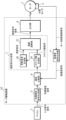
- 1 is a block diagram showing a configuration of a motor drive device according to an embodiment
- 4 is a flowchart showing an example of operation of the motor drive device according to the first embodiment.
- 4 is a timing chart showing an example of operation of the motor drive device according to the first embodiment.
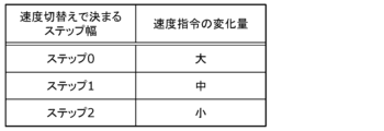
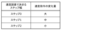
- 3B is a diagram showing an example of the relationship between the step width signal (steps 0 to 2) in FIG. 3A and the amount of change in the speed command signal;
- 10 is a flowchart showing an example of operation of a motor drive device according to a second embodiment.
- 10 is a timing chart showing an example of operation of the motor drive device according to the second embodiment.
- 5B is a diagram showing an example of the relationship between the step width signal (steps 0 to 2) in FIG.
- 13 is a timing chart showing an example of operation of the motor drive device according to the third embodiment.
- 13 is a timing chart showing a first operation example of the motor drive device according to the fourth embodiment.
- 13 is a flowchart illustrating a second operation example of the motor drive device according to the fourth embodiment.
- 13 is a flowchart illustrating a third operation example of the motor drive device according to the fourth embodiment.
- 13 is a flowchart showing a fourth operation example of the motor drive device according to the fourth embodiment.
- 13 is a flowchart showing a first operation example (initialization of a step width) of the motor drive device according to the fifth embodiment.
- 13 is a flowchart showing a second operation example (initialization of the timing of the update signal) of the motor drive device according to the fifth embodiment.
- FIG. 1 is a block diagram showing the configuration of a motor drive device 10 according to an embodiment. This figure also shows a microcomputer 3 that gives instructions (input command signals) to the motor drive device 10, a motor 1 such as a fan motor that is driven by the motor drive device 10, and a position sensor 2 such as a Hall element that detects the rotor position of the motor 1.
- a motor 1 such as a fan motor that is driven by the motor drive device 10
- a position sensor 2 such as a Hall element that detects the rotor position of the motor 1.
- the motor drive device 10 is a device that rotates the motor 1 at a target speed, and includes an actual speed signal generator 4, a target speed signal generator 5, a speed comparator 6, a speed command generator 7, and an output unit 8.
- the actual speed signal generator 4 generates an actual speed signal that indicates the actual speed, which is the number of rotations of the motor 1, based on the signal that indicates the rotor position of the motor 1 output by the position sensor 2.
- the target speed signal generator 5 generates a target speed signal indicating the target speed of the motor 1 based on instructions (input command signal) given by the microcomputer 3.
- the speed comparison unit 6 compares the actual speed indicated by the actual speed signal generated by the actual speed signal generation unit 4 with the target speed indicated by the target speed signal generation unit 5. For example, the speed comparison unit 6 outputs a speed error, which is the difference between the actual speed indicated by the actual speed signal and the target speed indicated by the target speed signal (for example, a difference with a polarity (sign) obtained by subtracting the target speed from the actual speed).
- a speed error which is the difference between the actual speed indicated by the actual speed signal and the target speed indicated by the target speed signal (for example, a difference with a polarity (sign) obtained by subtracting the target speed from the actual speed).
- the speed command generator 7 is a processing unit that generates a speed command signal in response to the output from the speed comparator 6, and has a step width generator 7A, an update signal generator 7B, and an integration calculation unit 7C.
- the step width generator 7A generates a step width signal indicating a step width having a positive/negative sign and magnitude corresponding to the magnitude of either the actual speed indicated by the actual speed signal or the target speed indicated by the target speed signal, based on the other, in response to the output from the speed comparator 6.
- the update signal generator 7B repeatedly generates update signals.
- the integration calculation unit 7C adds the step width indicated by the step width signal generated by the step width generator 7A to the immediately preceding speed command signal and outputs the result to the output unit 8.
- the output unit 8 generates a drive signal, such as a pulse width modulation signal, for driving the motor 1 from the speed command signal output from the speed command generation unit 7 and outputs the drive signal to the motor 1.
- a drive signal such as a pulse width modulation signal
- the components that make up motor drive device 10 may be realized in hardware using dedicated electronic circuits, or in software using a microcomputer or the like that is made up of a memory that stores programs, a processor that executes the programs, and input/output circuits (including A/D converters, D/A converters, digital input/output circuits, etc.).
- the various signals generated by motor drive device 10 may be analog signals in which the magnitude of the voltage indicates the content of the information, or digital signals in which the binary value or duty ratio indicates the content of the information.
- FIG. 2 is a flowchart showing an example of the operation of the motor drive device 10 according to the first embodiment.
- the step width generating unit 7A determines whether the polarity of the output from the speed comparing unit 6 has reversed (S10). If it determines that the polarity has not reversed (No in S10), it retains the current value as the step width (S11). On the other hand, if it determines that the polarity has reversed (Yes in S10), it then determines whether the current step width is a predetermined minimum value (S12).
- step width generator 7A determines that the current step width is the predetermined minimum value (Yes in S12), it retains the current value as the step width (S11). On the other hand, if the step width generator 7A determines that the current step width is not the minimum value (No in S12), it reduces the step width by one step (S13).
- the integration calculation unit 7C receives a step width signal indicating the step width held (S11) or updated (S13) by the step width generation unit 7A, and integrates the previous speed command signal by the step width indicated by the step width signal received from the step width generation unit 7A at the timing of the update signal received from the update signal generation unit 7B, and outputs the integrated speed command signal to the output unit 8 (S14).
- the motor drive device 10 repeats the above process (S10 to S14) at a rate faster than the timing of the update signal.
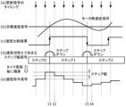
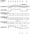
- FIG. 3A is a timing chart showing an example of operation of the motor drive device 10 according to the first embodiment.
- (a) to (e) in FIG. 3A respectively show the timing of the update signal, the target speed signal and the actual speed signal, the speed comparison result in the speed comparison unit 6, the step width signal determined by the speed switching (i.e., the step width signal generated in the step width generation unit 7A), and the speed command signal.
- FIG. 3B is a diagram showing an example of the relationship between the step width signal (steps 0 to 2) in FIG. 3A and the amount of change in the speed command signal.
- the step width generator 7A updates the step width from the previous "step 0" to "step 1" of smaller width and opposite polarity (here, negative sign) (FIG. 3A(d)).
- the integration calculator 7C outputs a speed command signal obtained by integrating the previous speed command signal with step 1, and the speed indicated by the speed command signal decreases by one step smaller (FIG. 3A(e)).
- the step width generator 7A updates the step width from the previous "step 1" to "step 2" of smaller width and opposite polarity (positive sign in this case) (FIG. 3A (d)).
- the integration calculator 7C outputs a speed command signal obtained by integrating the previous speed command signal by step 2, and the speed indicated by the speed command signal increases by an even smaller width (FIG. 3A (e)).
- the motor drive device 10 includes an actual speed signal generator 4 that generates an actual speed signal indicating the actual speed of the motor 1, a target speed signal generator 5 that generates a target speed signal indicating the target speed of the motor 1, a speed comparator 6 that compares the actual speed indicated by the actual speed signal with the target speed indicated by the target speed signal, a speed command generator 7 that generates a speed command signal in response to the output from the speed comparator 6, and an output unit 8 that generates a drive signal for driving the motor 1 from the speed command signal.
- an actual speed signal generator 4 that generates an actual speed signal indicating the actual speed of the motor 1
- a target speed signal generator 5 that generates a target speed signal indicating the target speed of the motor 1
- a speed comparator 6 that compares the actual speed indicated by the actual speed signal with the target speed indicated by the target speed signal
- a speed command generator 7 that generates a speed command signal in response to the output from the speed comparator 6, and an output unit 8 that generates a drive signal for driving the motor 1 from
- the speed command generator 7 includes a step width generator 7A that generates a step width signal indicating a step width having a positive/negative sign and a magnitude corresponding to the magnitude of the actual speed indicated by the actual speed signal and the target speed indicated by the target speed signal based on the other in response to the output of the speed comparator 6, an update signal generator 7B that repeatedly generates an update signal, and an integration calculation unit 7C that adds the step width indicated by the step width signal to the speed command signal at each timing of the repeatedly generated update signals and outputs the result.
- a step width generator 7A that generates a step width signal indicating a step width having a positive/negative sign and a magnitude corresponding to the magnitude of the actual speed indicated by the actual speed signal and the target speed indicated by the target speed signal based on the other in response to the output of the speed comparator 6, an update signal generator 7B that repeatedly generates an update signal, and an integration calculation unit 7C that adds the step width indicated by the step width signal to the speed command signal at each timing of the repeatedly generated update signals
- the motor driving method is a method of driving motor 1 by motor driving device 10, and includes an actual speed signal generation step (processing of actual speed signal generation unit 4) of generating an actual speed signal indicating the actual speed of motor 1, a target speed signal generation step (processing of target speed signal generation unit 5) of generating a target speed signal indicating the target speed of motor 1, a speed comparison step (processing of speed comparison unit 6) of comparing the actual speed indicated by the actual speed signal with the target speed indicated by the target speed signal, a speed command generation step (processing of speed command generation unit 7) of generating a speed command signal in accordance with the output from the speed comparison step, and a speed command generation step (processing of speed command generation unit 8) of driving motor 1 from the speed command signal.
- the speed command generation step includes an output step (processing of the output unit 8) for generating a drive signal for controlling the speed command signal, and a step width generation step (processing of the step width generation unit 7A) for generating a step width having a positive/negative sign and a magnitude corresponding to the magnitude of the actual speed indicated by the actual speed signal and the target speed indicated by the target speed signal based on the other, according to the output of the speed comparison step, an update signal generation step (processing of the update signal generation unit 7B) for repeatedly generating an update signal, and an integration calculation step (processing of the integration calculation unit 7C) for adding the step width to the speed command signal at each timing of the repeatedly generated update signal and outputting the result.
- an output step processing of the output unit 8 for generating a drive signal for controlling the speed command signal
- a step width generation step processing of the step width generation unit 7A for generating a step width having a positive/negative sign and a magnitude corresponding to the magnitude of the actual speed indicated by the actual speed signal and the target speed
- motor drive device 10 does not require complex PI control as in Patent Document 1, and does not require calculating a relationship between the speed command and the speed for each motor characteristic and storing it in memory or the like as in Patent Document 2, and speed control is realized with a simple configuration and without the need for adjustment for each motor.
- the step width generating unit 7A reduces the size of the step width when the magnitude relationship between the actual speed indicated by the output of the speed comparing unit 6 and the target speed is reversed. This gradually reduces the amount of adjustment to the speed command signal, ensuring that the actual speed converges to the target speed.
- three steps, 0 to 2 are set as the step width determined by the speed switching, but this number is not limited, and it may be set to two steps or four or more steps.
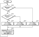
- FIG. 4 is a flowchart showing an example of the operation of the motor drive device 10 according to the second embodiment.
- the step width generating unit 7A judges whether the speed error output from the speed comparing unit 6 belongs to a predetermined range of "large” (S20). If it is judged that the speed error belongs to "large” (Yes in S20), it selects "step 0" which indicates the maximum step width of three predetermined step widths as the step width (S21). On the other hand, if it is judged that the speed error does not belong to "large” (No in S20), it then judges whether the speed error output from the speed comparing unit 6 belongs to a predetermined range of "medium” which is one step smaller than "large” (S22). The speed error indicates a signed difference obtained by subtracting the target speed from the actual speed, and the step width is set to a value with the opposite sign to the speed error. Also, "large” and “small” indicate the comparison result in absolute values.
- the step width generation unit 7A selects "Step 1" as the step width, which indicates the second largest step width of the three predetermined step widths (S23). On the other hand, if the speed error is determined not to be “medium” (No in S22), the step width generation unit 7A selects "Step 2" as the step width, which indicates the smallest step width of the three predetermined step widths (S24).
- the integration calculation unit 7C receives a step width signal indicating the step width selected by the step width generation unit 7A (S21, S23, S24), and integrates the previous speed command signal by the step width indicated by the step width signal received from the step width generation unit 7A at the timing of the update signal received from the update signal generation unit 7B, and outputs the integrated speed command signal to the output unit 8 (S25).
- the motor drive device 10 repeats the above process (S20 to S25) at a rate faster than the timing of the update signal.
- FIG. 5A is a timing chart showing an example of operation of the motor drive device 10 according to the second embodiment.
- (a) to (e) in FIG. 5A respectively show the timing of the update signal, the target speed signal and the actual speed signal, the speed error signal output from the speed comparison unit 6, the step width signal determined by the speed error (i.e., the step width signal generated by the step width generation unit 7A), and the speed command signal.
- FIG. 5B is a diagram showing an example of the relationship between the step width signal (steps 0 to 2) in FIG. 5A and the amount of change in the speed command signal.
- the step width generator 7A selects "Step 2" which has a positive sign and indicates the smallest step width (FIG. 5A (d)), and the integration calculator 7C outputs a speed command signal obtained by integrating the previous speed command signal with "Step 2".
- the speed indicated by the speed command signal increases by the smallest width (FIG. 5A (e)).
- the step width generation unit 7A selects "step 1" which has a negative sign and indicates a medium step width (Fig. 5A (d)), and the integration calculation unit 7C outputs a speed command signal obtained by integrating the previous speed command signal with "step 1", and as a result, the speed indicated by the speed command signal decreases by a medium amount (Fig. 5A (e)).
- the step width generation unit 7A selects "step 0" which has a negative sign and indicates the maximum step width (FIG. 5A (d)), and the integration calculation unit 7C outputs a speed command signal obtained by integrating the previous speed command signal with "step 0", and as a result, the speed indicated by the speed command signal decreases by the maximum width (FIG. 5A (e)).
- the speed comparison unit 6 outputs a speed error, which is the difference between the actual speed indicated by the actual speed signal and the target speed indicated by the target speed signal, and the step width generation unit 7A reduces the size of the step width when the speed error falls below a predetermined value.
- the speed error is below the predetermined value, the adjustment width of the speed command signal is reduced, ensuring that the actual speed converges to the target speed.
- three steps, 0 to 2 are set as the step width determined by the speed error, but this number is not limited and it may be set to two steps or four or more steps.
- Example 3 is an example of the operation of motor drive device 10 incorporating the controls of both Example 1 and Example 2, and is characterized in that the speed command signal is updated by adopting the smaller step width of the step width selected by the control of Example 1 and the step width selected by the control of Example 2.
- step width generation unit 7A reduces the size of the step width, and selects the smaller step width when this coincides with the case where the speed error output by speed comparison unit 6 becomes equal to or smaller than a predetermined value.
- FIG. 6 is a timing chart showing an example of operation of the motor drive device 10 according to the third embodiment.
- (a) to (g) in FIG. 6 respectively show the timing of the update signal, the target speed signal and the actual speed signal, the speed comparison result in the speed comparison unit 6, the step width signal determined by the speed switching, the step width signal determined by the speed error, the step width signal indicating the smaller step width of the two step width signals, and the speed command signal.
- step 0 with a positive sign is selected as the step width signal determined by the speed switching (FIG. 6(d)).
- the step width generating unit 7A selects "Step 0" (FIG. 6(d)) with a positive sign selected as the step width signal determined by the speed switch and "Step 2" (FIG. 6(e)) with a positive sign selected as the step width signal determined by the speed error, and outputs "Step 2" with a positive sign, which has the smaller step width, as the step width signal (FIG. 6(f)).
- the integration calculation unit 7C outputs a speed command signal obtained by integrating the immediately preceding speed command signal with "Step 2" with a positive sign, and as a result, the speed indicated by the speed command signal increases by the minimum width (FIG. 6(g)).
- the step width generating unit 7A selects "Step 1" with a negative sign, which has the smaller step width (because they are the same in this case) from "Step 1" with a negative sign, which is selected as the step width signal determined by the speed switch ((d) of FIG. 6) and "Step 1" with a negative sign, which is selected as the step width signal determined by the speed error ((e) of FIG. 6), as the step width signal ((f) of FIG. 6).
- the integration calculation unit 7C outputs a speed command signal obtained by integrating the previous speed command signal with "Step 1" with a negative sign, and as a result, the speed indicated by the speed command signal decreases by a moderate amount ((g) of FIG. 6).
- the step width generating unit 7A reduces the size of the step width when the magnitude relationship between the actual speed indicated by the output of the speed comparing unit 6 and the target speed is reversed, and selects the smaller step width when this coincides with the case where the speed error is equal to or less than a predetermined value. This simultaneously performs control to gradually reduce the adjustment amount for the speed command signal and control to reduce the adjustment amount of the speed command signal when the speed error is equal to or less than a predetermined value, making it possible to more reliably achieve convergence of the actual speed to the target speed.
- Example 4 The fourth embodiment is characterized in that a predetermined minimum value is set for the step width, and when a state in which the step width is at the minimum value continues, the update signal generating unit 7B extends the timing of the update signal.
- control of this embodiment 4 can be used in combination with any of the controls of the above-mentioned embodiments 1 to 3. Therefore, an operation example in which the control of this embodiment 4 is incorporated into the control of the above-mentioned embodiment 3 will be described as a first operation example of embodiment 4 using the timing chart of FIG. 7.
- FIG. 7 is a timing chart showing a first operation example of the motor drive device 10 according to the fourth embodiment.
- (a) to (g) in FIG. 7 respectively show the timing of the update signal, the target speed signal and the actual speed signal, the speed comparison result in the speed comparison unit 6, the step width signal determined by the speed switching, the step width signal determined by the speed error, the step width signal indicating the smaller step width of the two step width signals, and the speed command signal.
- the step width generator 7A selects "Step 2" with a negative sign, which has a smaller step width, and outputs it as the step width signal (FIG. 6(f)). Then, at time t2, out of "Step 2" (FIG. 7(d)) with a positive sign selected as the step width signal determined by the speed switch and "Step 1" (FIG.
- the step width generator 7A selects "Step 2" with a positive sign, which has a smaller step width, and outputs it as the step width signal (FIG. 6(f)).
- the step width is continuously at its minimum value (i.e., "step 2"). Therefore, at time t2, the update signal generator 7B detects that the step width signal indicating the minimum step width has been continuously output from the step width generator 7A, and extends the timing of the next update signal (time t3) ( Figure 7(a)).
- the update signal generating unit 7B detects that step width signals have been output continuously, it thereafter changes the period for outputting the update signal to, for example, twice the basic period.
- an update signal is output at time t3, when twice the previous period has elapsed, and at time t3, a speed command signal obtained by integrating the previous speed command signal by "step 2" with a positive sign is output from the integration calculation unit 7C, and the speed indicated by the speed command signal increases by a moderate amount ( Figure 7 (g)). If a similar event is detected again, the period for outputting the update signal is changed from twice the previous basic period to three times.
- a predetermined minimum value is set for the step width, and when a state in which the step width is at the minimum value continues, the update signal generating unit 7B extends the timing of the update signal. This reduces the frequency of adjustments to the speed command signal when a state in which the step width is at the minimum value continues, and it is possible to more reliably achieve the convergence of the actual speed to the target speed.
- the timing of the update signal is extended in the order of the basic period, double the period, triple the period, etc., but this extension pattern is not limited to this, and it may be extended in the order of, for example, the basic period, triple the period, six times the period, etc.
- control to extend the timing of the update signal is not limited to the case where the step width is continuously at the minimum value, as in the first operation example above, but can also be applied to other states.
- Figures 8A to 8C as second to fourth operation examples related to Example 4.
- FIG. 8A is a flowchart showing a second operation example of the motor drive device 10 according to the fourth embodiment.
- the update signal generating unit 7B monitors whether the magnitude relationship between the actual speed and the target speed indicated by the output of the speed comparing unit 6 has reversed (S30), and when it determines that the magnitude relationship between the actual speed and the target speed has reversed (Yes in S30), it extends the timing of the update signal (S31). Specifically, when the update signal generating unit 7B detects that the magnitude relationship between the actual speed and the target speed has reversed, it thereafter changes the period for outputting the update signal to, for example, twice the basic period. Note that when it does not determine that the magnitude relationship between the actual speed and the target speed has reversed (No in S30), the update signal generating unit 7B repeats the determination (S30) without performing any process related to extending the timing of the update signal.
- the update signal generating unit 7B extends the timing of the update signal when the magnitude relationship between the actual speed and the target speed indicated by the output of the speed comparing unit 6 is reversed. This reduces the frequency of adjustments to the speed command signal when the magnitude relationship between the actual speed and the target speed is reversed, ensuring that the actual speed converges to the target speed.
- FIG. 8B is a flowchart showing a third operation example of the motor drive device 10 according to the fourth embodiment.
- the update signal generating unit 7B monitors whether the speed error output by the speed comparing unit 6 is equal to or less than a predetermined value (S33), and when it determines that the speed error is equal to or less than the predetermined value (Yes in S33), it extends the timing of the update signal (S34). Specifically, when the update signal generating unit 7B detects that the speed error output by the speed comparing unit 6 is within a predetermined "small” range, it thereafter changes the period for outputting the update signal to, for example, twice the basic period. Note that when it does not determine that the speed error is equal to or less than the predetermined value (No in S33), the update signal generating unit 7B repeats the determination (S33) without performing any process related to extending the timing of the update signal.
- the speed comparison unit 6 outputs a speed error, which is the difference between the actual speed indicated by the actual speed signal and the target speed indicated by the target speed signal, and the update signal generation unit 7B extends the timing of the update signal when the speed error falls below a predetermined value. This reduces the frequency of adjustments to the speed command signal when the speed error falls below a predetermined value, ensuring that the actual speed converges to the target speed.
- FIG. 8C is a flowchart showing a fourth operation example of the motor drive device 10 according to the fourth embodiment.
- the update signal generating unit 7B performs control of the second operation example shown in FIG. 8A and control of the third operation example shown in FIG. 8B in parallel (S36).
- the update signal generating unit 7B determines whether the timing extension of the update signal under control of the second operation example and the timing extension of the update signal under control of the third operation example overlap in terms of timing (S37), and if it is determined that they overlap (Yes in S37), it extends the timing of the update signal to the longer one (if they are the same, the same timing) (S38).
- the update signal generation unit 7B will change it to the longer one, that is, three times the basic period.
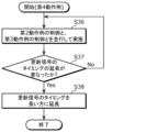
- the update signal generating unit 7B repeats the processing of steps S36 and S37 without performing processing related to extending the timing of the update signal.
- the update signal generation unit 7B extends the timing of the update signal, and when the speed error overlaps with a case where the speed error is equal to or smaller than a predetermined value, selects the longer timing of the update signal.
- the longer timing is selected, which further reduces the frequency of adjustments to the speed command signal and ensures that the actual speed converges to the target speed.
- Example 5 The fifth embodiment relates to control of the step size and initialization of the timing of the update signal.
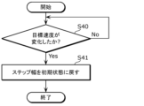
- FIG. 9A is a flowchart showing a first operation example (initialization of step width) of the motor drive device 10 according to the fifth embodiment.
- the step width generating unit 7A monitors the input command signal input to the target speed signal generating unit 5, and determines whether the target speed indicated by the input command signal has changed (S40). If it determines that the target speed has changed (Yes in S40), it resets the size of the step width to its initial state (S41). Specifically, if the step width generating unit 7A determines that the target speed has changed, it outputs a step width signal indicating "step 0" at the timing of the next update signal. Note that if it does not determine that the target speed has changed (No in S40), the step width generating unit 7A repeats the determination (S40) without performing any processing related to initializing the step width.
- the step width generating unit 7A returns the size of the step width to the initial state.
- the target speed changes, adjustment of the speed command signal is resumed using the initialized new step width for the new target speed, ensuring that the actual speed converges to the new target speed.
- control according to the first operation example of Example 5 can be used in combination with any of the controls of Examples 1 to 4 above.
- FIG. 9B is a flowchart showing a second operation example (initialization of the timing of the update signal) of the motor drive device 10 according to the fifth embodiment.
- the update signal generating unit 7B monitors the input command signal input to the target speed signal generating unit 5, and determines whether the target speed indicated by the input command signal has changed (S45). If it determines that the target speed has changed (Yes in S45), it returns the timing of the update signal to its initial state (S46). Specifically, if the update signal generating unit 7B determines that the target speed has changed, it outputs an update signal at a basic period that is predetermined as the initial value from the next update signal to be output. Note that if it does not determine that the target speed has changed (No in S45), the update signal generating unit 7B repeats the determination (S45) without performing processing related to the initialization of the timing of the update signal.
- the update signal generator 7B when the value of the target speed signal changes, the update signal generator 7B returns the timing of the update signal to the initial state. As a result, when the target speed changes, adjustment of the speed command signal is resumed for the new target speed using the newly initialized timing of the update signal, ensuring that the actual speed converges to the new target speed.
- control according to the second operation example of the fifth embodiment can be used in combination with the control of the fourth embodiment, which controls to extend the timing of the update signal.
- one of the first to third embodiments may be selected, with regard to the timing of the update signal, one of the first to fourth operation examples of the fourth embodiment may be selected, with regard to the initialization of the step width, the first operation example of the fifth embodiment may be selected, with regard to the initialization of the timing of the update signal, the second operation example of the fifth embodiment may be selected, and control may be performed using a combination of the selected embodiments and operation examples.
- the update signal generating unit 7B may generate the update signal based on the actual speed signal generated by the actual speed signal generating unit 4. More specifically, the update signal generating unit 7B may generate the update signal based on the rotor position signal used to generate the actual speed signal (i.e., the signal indicating the rotor position of the motor 1 output by the position sensor 2). For example, in the fourth embodiment, the update signal generating unit 7B may extend the timing of the update signal depending on the actual speed signal, and in the fifth embodiment, the update signal generating unit 7B may return the timing of the update signal to the initial state when not only the value of the target speed signal but also the value of the actual speed signal change.
- the motor drive device can also be realized as a program including each step of the motor drive method according to the present disclosure, and further as a computer-readable recording medium such as a DVD that stores such a program.
- the present disclosure can be used as a motor drive device that rotates a motor at a target speed, in particular as a motor drive device that has a simple configuration and performs speed control without the need for adjustment for each motor, for example, as a drive device for a fan motor.
Landscapes
- Engineering & Computer Science (AREA)
- Power Engineering (AREA)
- Control Of Electric Motors In General (AREA)
Priority Applications (3)
| Application Number | Priority Date | Filing Date | Title |
|---|---|---|---|
| JP2024554393A JPWO2024095789A1 (cg-RX-API-DMAC7.html) | 2022-11-01 | 2023-10-19 | |
| CN202380074741.1A CN120113146A (zh) | 2022-11-01 | 2023-10-19 | 马达驱动装置以及马达驱动方法 |
| US19/185,729 US20250253782A1 (en) | 2022-11-01 | 2025-04-22 | Motor drive device and motor drive method |
Applications Claiming Priority (2)
| Application Number | Priority Date | Filing Date | Title |
|---|---|---|---|
| JP2022175741 | 2022-11-01 | ||
| JP2022-175741 | 2022-11-01 |
Related Child Applications (1)
| Application Number | Title | Priority Date | Filing Date |
|---|---|---|---|
| US19/185,729 Continuation US20250253782A1 (en) | 2022-11-01 | 2025-04-22 | Motor drive device and motor drive method |
Publications (1)
| Publication Number | Publication Date |
|---|---|
| WO2024095789A1 true WO2024095789A1 (ja) | 2024-05-10 |
Family
ID=90930477
Family Applications (1)
| Application Number | Title | Priority Date | Filing Date |
|---|---|---|---|
| PCT/JP2023/037935 Ceased WO2024095789A1 (ja) | 2022-11-01 | 2023-10-19 | モータ駆動装置及びモータ駆動方法 |
Country Status (4)
| Country | Link |
|---|---|
| US (1) | US20250253782A1 (cg-RX-API-DMAC7.html) |
| JP (1) | JPWO2024095789A1 (cg-RX-API-DMAC7.html) |
| CN (1) | CN120113146A (cg-RX-API-DMAC7.html) |
| WO (1) | WO2024095789A1 (cg-RX-API-DMAC7.html) |
Citations (4)
| Publication number | Priority date | Publication date | Assignee | Title |
|---|---|---|---|---|
| JP2004088882A (ja) * | 2002-08-26 | 2004-03-18 | Brother Ind Ltd | 主軸モータの制御装置 |
| JP2011094451A (ja) * | 2009-11-02 | 2011-05-12 | Sumitomo (Shi) Construction Machinery Co Ltd | 建設機械の旋回制御装置 |
| JP2014194120A (ja) * | 2013-03-28 | 2014-10-09 | Sumitomo Heavy Ind Ltd | 電動旋回制御装置 |
| JP2018026947A (ja) * | 2016-08-10 | 2018-02-15 | 株式会社明電舎 | 速度制御システム |
-
2023
- 2023-10-19 WO PCT/JP2023/037935 patent/WO2024095789A1/ja not_active Ceased
- 2023-10-19 JP JP2024554393A patent/JPWO2024095789A1/ja active Pending
- 2023-10-19 CN CN202380074741.1A patent/CN120113146A/zh active Pending
-
2025
- 2025-04-22 US US19/185,729 patent/US20250253782A1/en active Pending
Patent Citations (4)
| Publication number | Priority date | Publication date | Assignee | Title |
|---|---|---|---|---|
| JP2004088882A (ja) * | 2002-08-26 | 2004-03-18 | Brother Ind Ltd | 主軸モータの制御装置 |
| JP2011094451A (ja) * | 2009-11-02 | 2011-05-12 | Sumitomo (Shi) Construction Machinery Co Ltd | 建設機械の旋回制御装置 |
| JP2014194120A (ja) * | 2013-03-28 | 2014-10-09 | Sumitomo Heavy Ind Ltd | 電動旋回制御装置 |
| JP2018026947A (ja) * | 2016-08-10 | 2018-02-15 | 株式会社明電舎 | 速度制御システム |
Also Published As
| Publication number | Publication date |
|---|---|
| CN120113146A (zh) | 2025-06-06 |
| JPWO2024095789A1 (cg-RX-API-DMAC7.html) | 2024-05-10 |
| US20250253782A1 (en) | 2025-08-07 |
Similar Documents
| Publication | Publication Date | Title |
|---|---|---|
| US9018872B2 (en) | Motor control circuit | |
| JP2014068522A (ja) | モータ制御装置及びモータ制御方法 | |
| JP2020043692A (ja) | モータの制御装置 | |
| US20200127654A1 (en) | Signal generating circuit and power supply device | |
| US8610394B2 (en) | Microcomputer for controlling ultrasonic motor, and method for controlling ultrasonic motor | |
| US5936564A (en) | Digital to analog converter using pulse width modulation and the controlling method thereof | |
| JP3251827B2 (ja) | 位置決め装置 | |
| CN110957945B (zh) | 电动机控制电路以及电动机控制装置 | |
| US7923979B2 (en) | Control system for dynamically adjusting output voltage of voltage converter | |
| CN120113146A (zh) | 马达驱动装置以及马达驱动方法 | |
| US7348770B2 (en) | Electronic device for interrupt signal control to acquire encoder speed information and a method thereof | |
| JP4784491B2 (ja) | モータ駆動装置 | |
| US7449849B2 (en) | Motor control circuit and method thereof | |
| JP7311957B2 (ja) | Dcモータの駆動回路およびそれを用いた電子機器 | |
| US20240305225A1 (en) | Motor driving device | |
| JP5722126B2 (ja) | 負荷適応型制御ループ切り替え方法及び負荷適応型帰還制御装置 | |
| JP2009118599A (ja) | Pwmインバータ装置 | |
| JP3266675B2 (ja) | コントローラ | |
| JP7012507B2 (ja) | Dcモータの駆動回路、駆動方法およびそれを用いた電子機器 | |
| JP3353558B2 (ja) | デッドタイム補償装置、デッドタイム補償方法、モータ駆動装置及びモータ駆動方法 | |
| JPH0797899B2 (ja) | パルス制御回路 | |
| JP2000312468A (ja) | スイッチング・レギュレータ制御回路 | |
| JP2935762B2 (ja) | 直流モータの速度制御装置 | |
| JP2006048563A (ja) | 定周期分散制御による電圧制御装置 | |
| JPH10108484A (ja) | 振動アクチュエータ駆動装置 |
Legal Events
| Date | Code | Title | Description |
|---|---|---|---|
| 121 | Ep: the epo has been informed by wipo that ep was designated in this application |
Ref document number: 23885551 Country of ref document: EP Kind code of ref document: A1 |
|
| WWE | Wipo information: entry into national phase |
Ref document number: 2024554393 Country of ref document: JP Ref document number: 202380074741.1 Country of ref document: CN |
|
| NENP | Non-entry into the national phase |
Ref country code: DE |
|
| WWP | Wipo information: published in national office |
Ref document number: 202380074741.1 Country of ref document: CN |
|
| 122 | Ep: pct application non-entry in european phase |
Ref document number: 23885551 Country of ref document: EP Kind code of ref document: A1 |