WO2024084700A1 - セキュリティシステムの点検器具および点検方法 - Google Patents
セキュリティシステムの点検器具および点検方法 Download PDFInfo
- Publication number
- WO2024084700A1 WO2024084700A1 PCT/JP2022/039351 JP2022039351W WO2024084700A1 WO 2024084700 A1 WO2024084700 A1 WO 2024084700A1 JP 2022039351 W JP2022039351 W JP 2022039351W WO 2024084700 A1 WO2024084700 A1 WO 2024084700A1
- Authority
- WO
- WIPO (PCT)
- Prior art keywords
- connector
- switch
- state
- controller
- case
- Prior art date
- Legal status (The legal status is an assumption and is not a legal conclusion. Google has not performed a legal analysis and makes no representation as to the accuracy of the status listed.)
- Ceased
Links
Images


Classifications
-
- E—FIXED CONSTRUCTIONS
- E05—LOCKS; KEYS; WINDOW OR DOOR FITTINGS; SAFES
- E05B—LOCKS; ACCESSORIES THEREFOR; HANDCUFFS
- E05B47/00—Operating or controlling locks or other fastening devices by electric or magnetic means
-
- G—PHYSICS
- G01—MEASURING; TESTING
- G01R—MEASURING ELECTRIC VARIABLES; MEASURING MAGNETIC VARIABLES
- G01R31/00—Arrangements for testing electric properties; Arrangements for locating electric faults; Arrangements for electrical testing characterised by what is being tested not provided for elsewhere
Definitions
- This disclosure relates to an inspection tool and method for a security system.
- Patent Document 1 discloses an example of a security system.
- the security system includes an electric lock, a controller, and a line connecting the electric lock and the controller.
- the controller receives signals indicating the open/closed state of the door and signals indicating the locked/unlocked state from the electric lock via the line.
- the controller outputs a lock/unlock request to the electric lock via the line.
- a failure may occur due to a factor occurring in the controller, the line, or the electric lock. If the location where the cause of the failure occurred is not identified, the efficiency of the inspection work to deal with the security system failure may decrease.
- This disclosure is directed to solving such problems.
- This disclosure provides an inspection tool and an inspection method that can improve the efficiency of security system inspection work.
- the inspection tool is an inspection tool for a security system that includes an electric lock and a controller provided on a door, the controller and the electric lock are connected through a first connector on the controller side and a second connector on the electric lock side, the controller monitors a first signal indicating the open/closed state of the door through the first connector and the second connector, the controller monitors a second signal indicating the locked/unlocked state of the electric lock through the first connector and the second connector, and outputs a control signal to the electric lock to lock or unlock it through the first connector and the second connector, and is equipped with a third connector connected to the first connector in place of the second connector, a first switch connected to the third connector and switching the state of the first signal, a second switch connected to the third connector and switching the state of the second signal, and a jack connected to the third connector for connecting a probe of a tester that detects the control signal output from the controller.
- the inspection method is a method for inspecting the security system using the above-mentioned inspection tool, and includes a disconnection step of disconnecting the second connector from the first connector, a connector connecting step of connecting the third connector to the first connector after the disconnection step, a tester connecting step of connecting the probe of the tester to the jack, an input step of inputting a signal to unlock the electric lock to the controller after the connector connecting step and the tester connecting step, an output confirmation step of confirming, after the input step, the output of the control signal from the controller by the tester with the probe connected to the jack, a simulated unlocking step of switching the state of the second signal to the unlocked state of the electric lock by operating the second switch after the output confirmation step, a simulated door-opening step of switching the state of the first signal to the open state of the door by operating the first switch after the simulated unlocking step, and a monitoring confirmation step of confirming that the controller recognizes the open/closed state of the door as the open state after the simulated door-opening step.
- the inspection method is a method for inspecting the security system using the above-mentioned inspection tool, and includes a disconnecting step of disconnecting the second connector from the first connector, a connector connecting step of connecting the third connector to the first connector after the disconnecting step, a tester connecting step of connecting the probe of the tester to the jack, a simulated door closing step of switching the state of the first signal to a closed state of the door by operating the first switch after the connector connecting step and the tester connecting step, an output confirmation step of confirming the output of the control signal from the controller by the tester with the probe connected to the jack after the output confirmation step, a simulated locking step of switching the state of the second signal to a locked state of the electric lock by operating the second switch after the output confirmation step, and a monitoring confirmation step of confirming that the controller recognizes the locked/unlocked state of the electric lock as a locked state after the simulated locking step.
- the inspection tool or inspection method disclosed herein can improve the efficiency of security system inspection work.
- FIG. 1 is a configuration diagram of a security system according to a first embodiment. 1 is a configuration diagram of an electric lock and an inspection tool according to a first embodiment. FIG. 1 is a perspective view of an inspection tool according to a first embodiment. FIG. 1 is a perspective view of an inspection tool according to a first embodiment. FIG. 1 is a perspective view of an inspection tool according to a first embodiment. FIG.
- FIG. 1 is a configuration diagram of a security system 1 according to the first embodiment.
- Security system 1 is a system that enhances crime prevention, for example, by physically preventing intrusion into a protected area.
- the protected area is, for example, an area inside or outside a building.
- An entrance/exit is provided at the boundary of the protected area through which users who can enter the area pass.
- the entrance/exit is, for example, the front door of a building, or the entrance/exit of a room inside a building.
- a door 2 is provided at the entrance/exit.
- Security system 1 comprises an electric lock 3, a reader 4, and a controller 5.
- the electric lock 3 is a device that restricts the opening and closing of the door 2.
- the electric lock 3 is provided on the door 2.
- the door 2 When the electric lock 3 is in a locked state, the door 2 is kept in a closed state.
- the electric lock 3 is in an unlocked state, the door 2 can be opened and closed.
- the electric lock 3 locks and unlocks, for example, by inserting and removing a latch into a receiver provided on the frame of the door 2.
- the reader 4 is a device that reads authentication information for authenticating a user.
- the authentication information is, for example, identification information that identifies a user.
- the identification information may be information stored on a card or tag held by the user, or may be the user's own biometric information such as fingerprint information, vein information, or iris information.
- the reader 4 is equipped with a function for reading the user's identification information.
- the authentication information may be information that is kept secret from anyone other than the user, such as a PIN number.
- the reader 4 is equipped with a function for accepting input of authentication information via a numeric keypad or touch panel.
- the reader 4 is provided, for example, outside the boundary of the area to be protected.
- the reader 4 may also be provided inside the boundary of the area.
- the controller 5 is a device that controls the electric lock 3.
- the controller 5 and the electric lock 3 are electrically connected through a first communication path 6.
- the first communication path 6 is a wired communication path for communicating electric signals and the like.
- a first connector 7 and a second connector 8 are provided, which are detachably connected.
- the first connector 7 is a connector on the controller 5 side in the first communication path 6.
- the second connector 8 is a connector on the electric lock 3 side in the first communication path 6. Connectors other than the first connector 7 and the second connector 8 may be provided in the first communication path 6.
- the first connector 7 is a connector on the controller 5 side that is closest to the electric lock 3 in the first communication path 6.
- the second connector 8 may be a part of the electric lock 3.
- the controller 5 and the reader 4 are electrically connected through a second communication path 9.
- the second communication path 9 is, for example, a wired communication path for communicating electric signals and the like.
- the controller 5 monitors the first signal indicating the open/closed state of the door 2 and the second signal indicating the locked/unlocked state of the electric lock 3 through the first communication path 6.
- the authentication information read by the reader 4 is output to the controller 5 through the second communication path 9.
- the controller 5 determines whether the user corresponding to the authentication information is allowed to pass through based on the authentication information read by the reader 4.
- the controller 5 determines that the user is allowed to pass through, it outputs a control signal through the first communication path 6 to cause the electric lock 3 to unlock.
- the controller 5 determines that the electric lock 3 is unlocked and the door 2 has changed from an open state to a closed state based on the first and second signals, it outputs a control signal through the first communication path 6 to cause the electric lock 3 to lock.
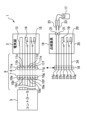
- FIG. 2 is a diagram showing the configuration of the electric lock 3 and the inspection tool 16 according to the first embodiment.
- the first connector 7 includes first contact 10a, first contact 10b, first contact 10c, first contact 10d, first contact 10e, first contact 10f, and first contact 10g.
- the second connector 8 includes second contact 11a, second contact 11b, second contact 11c, second contact 11d, second contact 11e, second contact 11f, and second contact 11g. When the first connector 7 and the second connector 8 are connected, the first contact 10a and the second contact 11a are connected.
- the electric lock 3 includes a locking/unlocking operation unit 13, an opening/closing detection unit 14, and a locking/unlocking detection unit 15.
- the locking/unlocking unit 13 is a part that is responsible for the mechanical operations of the electric lock 3, such as inserting and removing a latch into a receiving device.
- the locking/unlocking unit 13 mechanically operates the latch, etc., for example, by passing electricity through a solenoid.
- the locking/unlocking unit 13 is connected to the second contacts 11a and 11b.
- the locking/unlocking unit 13 mechanically operates the latch, etc., based on control signals input from the controller 5 through the first contacts 10a and 10b and the second contacts 11a and 11b.
- the open/close detection unit 14 is a part that detects the open/close state of the door 2.
- the open/close detection unit 14 is connected to the second contact 11c and the second contact 11d.
- the open/close detection unit 14 is, for example, a single-throw microswitch whose state is switched according to the open/close state of the door 2.
- the first signal representing the open/close state of the door 2 is an electric signal such as a voltage corresponding to the state of the microswitch.
- the open/close detection unit 14 is configured so that the second contact 11c and the second contact 11d are disconnected when the door 2 is in the open state, that is, the open state.
- the open/close detection unit 14 is configured so that the second contact 11c and the second contact 11d are connected when the door 2 is in the closed state, that is, the closed state.
- the open/close state detected by the open/close detection unit 14 is monitored by the controller 5 as a first signal through the first contact 10c and the first contact 10d and the second contact 11c and the second contact 11d.
- the locking/unlocking detection unit 15 is a part responsible for detecting the locked/unlocked state of the electric lock 3.
- the locking/unlocking detection unit 15 is connected to the second contact 11e, the second contact 11f, and the second contact 11g.
- the locking/unlocking detection unit 15 is, for example, a double-throw microswitch whose state is switched depending on the position of a part that operates mechanically when locking/unlocking, such as a latch.
- the second signal indicating the locking/unlocking of the electric lock 3 is an electrical signal such as a voltage corresponding to the state of the microswitch.
- the locking/unlocking detection unit 15 is configured so that the second contact 11e and the second contact 11f are connected when the electric lock 3 is in the unlocked state. At this time, the locking/unlocking detection unit 15 is configured so that the second contact 11f and the second contact 11g are connected when the locking/unlocking detection unit 15 is in the locked state.
- the locked/unlocked state detected by the lock/unlock detection unit 15 is monitored by the controller 5 as a second signal through the first contact 10e, the first contact 10f, and the first contact 10g, and the second contact 11e, the second contact 11f, and the second contact 11g.
- a malfunction may occur in the security system 1, for example, the electric lock 3 may not lock or unlock properly.
- an inspection of the security system 1 is performed.
- the worker inspecting the security system 1 uses the inspection tool 16 and the tester 17 to identify the location where the cause of the malfunction has occurred.
- the tester 17 is a detector such as a general-purpose, portable circuit tester that detects electrical signals such as current or voltage.
- the inspection tool 16 includes a third connector 18, a first switch 19, a second switch 20, and a pair of jacks 21.
- the third connector 18 is a connector that can be connected to the first connector 7 in place of the second connector 8.
- the third connector 18 includes third contacts 22a, 22b, 22c, 22d, 22e, 22f, and 22g.
- the first contact 10a and the third contact 22a are connected.
- the first contact 10b and the third contact 22b are connected, the first contact 10c and the third contact 22c are connected, the first contact 10d and the third contact 22d are connected, the first contact 10e and the third contact 22e are connected, the first contact 10f and the third contact 22f are connected, and the first contact 10g and the third contact 22g are connected.
- the first switch 19 is a switch that simulates the operation of the open/close detection unit 14.
- the first switch 19 is a single-throw switch.
- the first switch 19 is, for example, a toggle switch.
- the first switch 19 is connected to the third contact 22c and the third contact 22d of the third connector 18.
- the first switch 19 simulates the operation of the open/close detection unit 14 when the door 2 is in the open state by disconnecting the third contact 22c and the third contact 22d, i.e., by being in the open state.
- the first switch 19 simulates the operation of the open/close detection unit 14 when the door 2 is in the closed state by connecting the third contact 22c and the third contact 22d, i.e., by being in the closed state.
- the first switch 19 maintains the state simulating either the open state or the closed state until the state is switched by an external operation by an operator or the like.
- the second switch 20 is a switch that simulates the operation of the lock/unlock detection unit 15.
- the second switch 20 is a double-throw switch.
- the second switch 20 is, for example, a toggle switch.
- the second switch 20 is connected to the third contacts 22e, 22f, and 22g of the third connector 18.
- the second switch 20 simulates the operation of the lock/unlock detection unit 15 when the electric lock 3 is in an unlocked state by connecting the third contacts 22e and 22f.
- the second switch 20 simulates the operation of the lock/unlock detection unit 15 when the electric lock 3 is in an unlocked state by connecting the third contacts 22f and 22g.
- the second switch 20 maintains a state that simulates either the locked state or the unlocked state until the state is switched by an external operation by an operator or the like.
- Each jack 21 is a part for connecting a probe 23 of the tester 17.
- One jack 21 is connected to the third contact 22a of the third connector 18.
- the other jack 21 is connected to the third contact 22b of the third connector 18.
- Each jack 21 is, for example, a jack 21 that is connected by inserting a needle-shaped probe 23.
- Each jack 21 is equipped with a function for holding the connected probe 23, for example by elastic force, so that it does not fall off.
- the third connector 18 is connected to the first switch 19, the second switch 20, and each of the jacks 21 through conductors 24.
- the conductors 24 are made of, for example, multiple flexible lead wires.
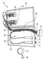
- FIGS. 3 and 4 are perspective views of the inspection tool 16 according to the first embodiment.
- the inspection tool 16 is shown in a state in which it is used to inspect the security system 1.
- the inspection tool 16 includes a case 25.
- the case 25 is a part that forms the outer shell of the inspection tool 16.
- the case 25 is, for example, rectangular in shape.
- the case 25 has a lid 26 that can be opened and closed.
- FIG. 3 shows the inspection tool 16 with the lid 26 of the case 25 closed.
- the operating part of the first switch 19 is disposed on the outer surface of the case 25.
- the operating part of the second switch 20 is disposed on the outer surface of the case 25.
- the first switch 19 and the second switch 20 are disposed on the lid 26 of the case 25.
- Each jack 21 is disposed on the outer surface of the case 25. In this example, each jack 21 is disposed on a side of the case 25.
- the third connector 18 is provided so that it can be connected to the first connector 7 on the outside of the case 25 when the lid 26 of the case 25 is closed.
- the third connector 18 is connected to the first switch 19, the second switch 20, and each of the jacks 21 via conductors 24 that can be pulled out to the outside of the case 25 when the lid 26 is closed.
- a notch 27 is provided on the edge of the opening when the lid 26 is opened.
- the conductor 24 to which the third connector 18 is connected is pulled out to the outside of the case 25 through the notch 27 of the case 25.
- the third connector 18 can be stored inside the case 25 together with the conductor 24 by removing the conductor 24 from the notch 27 and folding it back.
- the inspection tool 16 includes a plurality of fasteners 28.
- Each fastener 28 is a member that fastens the conductor 24 to the case 25.
- Each fastener 28 is, for example, a cable tie.
- the fastener 28, which is a cable tie fastens the conductor 24 to the case 25 by, for example, fastening the portion between a pair of small holes (not shown) provided in the case 25 and the conductor 24 together.
- each fastener 28 may be a hanger that is adhered to the case 25 and fastens the conductor 24 by hanging it on it.
- the plurality of fasteners 28 are arranged along the inner surface of the case 25. As a result, the portion of the conductor 24 that is fastened to the plurality of fasteners 28 is arranged inside the case 25 so as to run along the inner surface.
- the inspection tool 16 includes a hook 29.
- the hook 29 is a component that can be stored inside the case 25.
- the case 25 has a hanging hole 30 for hanging the hook 29.
- the hanging hole 30 is provided on the bottom surface of the case 25 that faces the lid 26 of the case 25 when it is closed.
- the hook 29 has an attachment portion 31 that is detachably attached to the door 2.
- the attachment portion 31 is, for example, a magnet or a suction cup.
- the inspection work is carried out, for example, by multiple workers.
- the workers may perform each step of the inspection work in a different order to the extent possible, or may perform the steps in parallel to the extent possible.
- the first connector 7 and the second connector 8 are connected. If a malfunction occurs in the security system 1, an operator will carry out an inspection. The operator will bring the inspection tool 16, with the third connector 18, the conductor 24, and the hook 29 stored inside the case 25 and the lid 26 closed, and the tester 17 to the location where the door 2 is installed.
- the worker removes the second connector 8 from the first connector 7. At this time, the worker may remove the second connector 8 while leaving the main body of the electric lock 3 attached to the door 2.
- the worker opens the lid 26 of the case 25 of the inspection tool 16 and takes the third connector 18 together with the conductor 24 out of the case 25.
- the worker hooks the conductor 24, which is connected to the third connector 18, into the notch 27 of the case 25.
- the worker takes the hook 29 out of the case 25.
- the worker closes the lid 26 of the case 25 with the third connector 18 out of the case 25.
- the worker connects the third connector 18 to the first connector 7.
- each jack 21 holds the inserted probes 23 of the tester 17 so that they do not fall out.
- the worker attaches the hook 29 to the surface of the door 2.
- the worker attaches the case 25 to the door 2 by hanging the hook 29 through the hanging hole 30 of the case 25.
- the worker performs an unlocking operation test, for example, as follows. Before the unlocking operation test, the worker sets the first switch 19 to a state simulating the closed state of the door 2, and sets the second switch 20 to a state simulating the locked state of the electric lock 3. At this time, the controller 5 monitors the state of the inspection tool 16, which simulates the states of the door 2 and the electric lock 3, through the first and second signals, and determines that the door 2 is closed and the electric lock 3 is locked.
- the worker has the reader 4 read the authentication information.
- the authentication information read at this time may be the normal authentication information of a user who is permitted to pass through the entrance/exit of the protected area, or it may be authentication information specifically for inspection work.
- the reader 4 outputs the read authentication information to the controller 5 via the second communication path 9.
- the controller 5 determines whether the user corresponding to the authentication information is permitted to pass through. If it is determined that the user is permitted to pass through, the controller 5 outputs a control signal to the electric lock 3 to unlock it.
- the worker checks the output of the control signal from the controller 5 using a tester 17 with a probe 23 connected to a jack 21.
- the worker checks whether a normal control signal has been output based on, for example, the presence or absence of an output control signal, the signal strength, or the duration of the signal output. If the worker is unable to confirm that a normal control signal has been output, he or she determines that an abnormality may have occurred in the controller 5 or in the first communication path 6 on the controller 5 side from the third connector 18.
- the worker confirms that a normal control signal has been output, he or she operates the second switch 20 to switch the state of the second signal.
- the second switch 20 switches the state of the second signal from a state corresponding to a locked state to a state corresponding to an unlocked state. In this way, the second switch 20 simulates the unlocking operation of the electric lock 3.
- the worker After simulating the unlocking operation of the electric lock 3 with the second switch 20, the worker operates the first switch 19 to switch the state of the first signal.
- the first switch 19 switches the state of the first signal from a state corresponding to a closed state to a state corresponding to an open state. In this way, the first switch 19 simulates the opening operation of the door 2.
- controller 5 After simulating the opening operation of door 2 with first switch 19, the worker confirms that controller 5 recognizes the open/closed state of door 2 as the open state. The worker confirms the state recognized by controller 5, for example, through a display panel provided on controller 5 or an information terminal connected to controller 5.
- the worker determines that the controller 5 and the first communication path 6 on the controller 5 side from the third connector 18 are normal with respect to unlocking the electric lock 3. At this time, if there is a malfunction in the security system 1 with respect to unlocking the electric lock 3, the worker determines that there is a possibility that an abnormality has occurred in the electric lock 3 that may be causing the malfunction.
- the worker also performs a locking operation test, for example, as follows. Before the locking operation test, the worker sets the first switch 19 to a state simulating an open state of the door 2, and sets the second switch 20 to a state simulating an unlocked state of the electric lock 3. At this time, the controller 5 monitors the state of the inspection tool 16 simulating the states of the door 2 and the electric lock 3 through the first and second signals, and determines that the door 2 is open and the electric lock 3 is unlocked. The worker may perform the locking operation test following the unlocking operation test, or may perform the locking operation test before the unlocking operation test.
- the worker operates to switch the state of the first switch 19.
- the first switch 19 switches the state of the first signal from a state corresponding to an open state to a state corresponding to a closed state. In this way, the first switch 19 simulates the closing operation of the door 2.
- the controller 5 determines based on the first signal and the second signal that the electric lock 3 is unlocked and that the door 2 has changed from an open state to a closed state. At this time, the controller 5 outputs a control signal to the electric lock 3 to lock it.
- the worker checks the output of the control signal from the controller 5 using a tester 17 with a probe 23 connected to a jack 21.
- the worker checks whether a normal control signal has been output based on, for example, the presence or absence of an output control signal, the signal strength, or the duration of the signal output. If the worker is unable to confirm that a normal control signal has been output, he or she determines that an abnormality may have occurred in the controller 5 or in the first communication path 6 on the controller 5 side from the third connector 18.
- the worker confirms that a normal control signal has been output, he or she operates the second switch 20 to switch the state of the second signal.
- the second switch 20 switches the state of the second signal from a state corresponding to the unlocked state to a state corresponding to the locked state. In this way, the second switch 20 simulates the locking operation of the electric lock 3.
- the worker After simulating the locking operation of the electric lock 3 with the second switch 20, the worker confirms that the controller 5 recognizes the locked/unlocked state of the electric lock 3 as the locked state.
- the worker confirms the state recognized by the controller 5, for example, through a display panel provided on the controller 5 or an information terminal connected to the controller 5.
- the operator determines that there may be an abnormality in the controller 5 or in the first communication path 6 on the controller 5 side from the third connector 18.
- the worker determines that the controller 5 and the first communication path 6 on the controller 5 side from the third connector 18 are normal with respect to locking the electric lock 3. At this time, if there is a malfunction in the security system 1 with respect to locking the electric lock 3, the worker determines that there is a possibility that an abnormality has occurred in the electric lock 3 that may be causing the malfunction.
- the worker After the worker confirms that the first communication path 6 on the controller 5 side from the controller 5 and the third connector 18 is normal, for example, the worker pulls out the probe 23 of the tester 17 from each jack 21 to disconnect the tester 17 and the inspection tool 16.
- the worker removes the hanging hole 30 of the case 25 from the hook 29.
- the worker removes the third connector 18 from the first connector 7.
- the worker removes the hook 29 from the surface of the door 2.
- the worker opens the lid 26 of the case 25 of the inspection tool 16 and stores the third connector 18 together with the conductor 24 inside the case 25.
- the worker stores the hook 29 inside the case 25.
- the worker closes the lid 26 of the case 25 with the third connector 18, conductor 24, and hook 29 stored inside the case 25.
- the worker After removing the inspection tool 16 in this way, the worker replaces or adjusts the electric lock 3 that may have an abnormality.
- the security system 1 includes the electric lock 3 provided on the door 2, and the controller 5.
- the controller 5 and the electric lock 3 are connected through the first connector 7 on the controller 5 side and the second connector 8 on the electric lock 3 side.
- the controller 5 monitors a first signal indicating the open/closed state of the door 2 through the first connector 7 and the second connector 8.
- the controller 5 monitors a second signal indicating the locked/unlocked state of the electric lock 3 through the first connector 7 and the second connector 8.
- the controller 5 outputs a control signal for locking/unlocking to the electric lock 3 through the first connector 7 and the second connector 8.
- the inspection tool 16 includes a third connector 18, a first switch 19, a second switch 20, and a jack 21.
- the third connector 18 is connected to the first connector 7 instead of the second connector 8.
- the first switch 19 is connected to the third connector 18.
- the first switch 19 switches the state of a first signal.
- the second switch 20 is connected to the third connector 18.
- the second switch 20 switches the state of a second signal.
- the jack 21 is connected to the third connector 18.
- a probe 23 of the tester 17 that detects a control signal output from the controller 5 is connected to the jack 21.
- the inspection method according to the first embodiment is performed using an inspection tool 16.
- the inspection method includes a disconnection step, a connector connection step, a tester connection step, an input step, an output confirmation step, a simulated unlocking step, a simulated door opening step, and a monitoring confirmation step.
- the disconnection step is a step of removing the second connector 8 from the first connector 7.
- the connector connection step is performed after the disconnection step.
- the connector connection step is a step of connecting the third connector 18 to the first connector 7.
- the tester connection step is a step of connecting the probe 23 of the tester 17 to the jack 21.
- the input step is performed after the connector connection step and the tester connection step.
- the input step is a step of inputting a signal such as an authentication signal for unlocking the electric lock 3 to the controller 5.
- the output confirmation step is performed after the input step.
- the output confirmation step is a step of confirming the output of a control signal from the controller 5 by the tester 17 with the probe 23 connected to the jack 21.
- the simulated unlocking step is performed after the output confirmation step.
- the simulated unlocking process is a process of switching the state of the second signal to the unlocked state of the electric lock 3 by operating the second switch 20.
- the simulated door-opening process is performed after the simulated unlocking process.
- the simulated door-opening process is a process of switching the state of the first signal to the open state of the door 2 by operating the first switch 19.
- the monitoring confirmation process is performed after the simulated door-opening process.
- the monitoring confirmation process is a process of confirming that the controller 5 recognizes the open/closed state of the door 2 as the open state.
- the inspection method according to the first embodiment is performed using an inspection tool 16.
- the inspection method includes a disconnection step, a connector connection step, a tester connection step, a simulated door-closing step, an output confirmation step, a simulated locking step, and a monitoring confirmation step.
- the disconnection step is a step of removing the second connector 8 from the first connector 7.
- the connector connection step is performed after the disconnection step.
- the connector connection step is a step of connecting the third connector 18 to the first connector 7.
- the tester connection step is a step of connecting the probe 23 of the tester 17 to the jack 21.
- the simulated door-closing step is performed after the connector connection step and the tester connection step.
- the simulated door-closing step is a step of switching the state of the first signal to the closed state of the door 2 by operating the first switch 19.
- the output confirmation step is performed after the simulated door-closing step.
- the output confirmation step is a step of confirming the output of a control signal from the controller 5 by the tester 17 with the probe 23 connected to the jack 21.
- the simulated locking step is performed after the output confirmation step.
- the simulated locking process is a process of switching the state of the second signal to the locked state of the electric lock 3 by operating the second switch 20.
- the monitoring confirmation process is performed after the simulated locking process.
- the monitoring confirmation process is a process of confirming that the controller 5 recognizes the locked/unlocked state of the electric lock 3 as the locked state.
- the inspection tool 16 simulating the door 2 and the electric lock 3 from the controller 5 and the third connector 18, so that the location where the abnormality that caused the failure occurred can be efficiently identified.
- Abnormalities occur relatively often in the electric lock 3, which includes mechanically operated parts, so the efficiency of the inspection work can be improved by quickly confirming that the other parts are normal.
- the inspection tool 16 can simulate both the opening and closing of the door 2 and the locking and unlocking of the electric lock 3, so that the operation of the controller 5 and the like can be confirmed more reliably. This makes it less likely that rework will occur, and the efficiency of the inspection work can be improved.
- the worker since the worker's hands are free after performing the operation to switch the state with the inspection tool 16, the worker can easily perform other work.
- the connection of the inspection tool 16 is made by connector connection, the connection of the inspection tool 16 and the controller 5 can be made more easily and reliably.
- the output of the control signal can be confirmed using a general-purpose tester 17, the worker can minimize the equipment he or she needs to bring to the work site where the inspection work is performed.
- the inspection tool 16 also includes a case 25 having an openable and closable lid 26.
- the third connector 18 is arranged outside the case 25 so as to be connectable to the first connector 7.
- the first switch 19 is arranged on the outer surface of the case 25.
- the second switch 20 is arranged on the outer surface of the case 25.
- the jack 21 is arranged on the outer surface of the case 25.
- This configuration makes it possible to store small parts or documents necessary for inspection work inside the case 25. This increases convenience for the workers performing the inspection work.
- a notch 27 is provided on the edge of the opening when the lid 26 is opened.
- the third connector 18 is connected to the first switch 19, the second switch 20, and the jack 21 through a conductor 24 that can be pulled out from the notch 27 to the outside of the case 25.
- the third connector 18 can be stored inside the case 25 together with the conductor 24.
- This configuration allows the third connector 18 to be stored inside the case 25 when the inspection tool 16 is transported. This improves convenience for the worker performing the inspection work.
- the third connector 18 that connects to the first connector 7 is connected to a flexible conductor 24 and pulled out to the outside of the case 25, making the process of connecting the first connector 7 and the third connector 18 easier.
- the conductor 24 is also secured to the inside of the case 25 by a number of fasteners 28 arranged along the inner surface of the case 25.
- This configuration provides more space inside the case 25 for storing parts and the like, improving convenience for workers performing inspection work.
- the conductor 24 is less likely to move inside the case 25, preventing the conductor 24 from being pinched when the case 25 is opened or closed.
- the inspection tool 16 also includes a hook 29.
- the hook 29 can be stored in the case 25.
- the hook 29 has an attachment portion 31 that is detachably attached to the door 2.
- the case 25 is provided with a hanging hole 30 through which the hook 29 can be hung.
- the attachment portion 31 may be provided directly on the case 25. In this case, the attachment portion 31 is provided, for example, on the outside of the bottom surface of the case 25.
- This configuration allows the worker to attach the inspection tool 16 to the door 2 and perform the work without having to hold it in his or her hands, making the inspection process more efficient.
- the jack 21 also holds the probe 23 of the tester 17 so that it does not fall off.
- an unlocking switch for unlocking the electric lock 3 may be provided, for example, inside the protected area. Since a person inside the protected area is usually a user who is permitted to pass through the entrance, the unlocking switch does not need to read the authentication information of the user.
- the unlocking switch When the unlocking switch is operated, it inputs a signal representing the operation to the controller 5 via the second communication path 9 or the like.
- the controller 5 determines, for example, based on the first signal and the second signal that the door 2 is closed and the electric lock 3 is locked, if a signal representing the operation of the unlocking switch is input, the controller 5 outputs a control signal via the first communication path 6 to cause the electric lock 3 to unlock.
- the signal input to the controller 5 in the input process may be a signal representing the operation. Also, the signal input to the controller 5 in the input process may be input by an operator operating the controller 5 itself.
- the inspection tool and inspection method disclosed herein can be applied to security system inspection work.
Landscapes
- Physics & Mathematics (AREA)
- General Physics & Mathematics (AREA)
- Lock And Its Accessories (AREA)
- Testing Electric Properties And Detecting Electric Faults (AREA)
Priority Applications (3)
| Application Number | Priority Date | Filing Date | Title |
|---|---|---|---|
| JP2024551187A JP7816549B2 (ja) | 2022-10-21 | 2022-10-21 | セキュリティシステムの点検器具 |
| CN202280101145.3A CN120051611A (zh) | 2022-10-21 | 2022-10-21 | 安全系统的检查器具以及检查方法 |
| PCT/JP2022/039351 WO2024084700A1 (ja) | 2022-10-21 | 2022-10-21 | セキュリティシステムの点検器具および点検方法 |
Applications Claiming Priority (1)
| Application Number | Priority Date | Filing Date | Title |
|---|---|---|---|
| PCT/JP2022/039351 WO2024084700A1 (ja) | 2022-10-21 | 2022-10-21 | セキュリティシステムの点検器具および点検方法 |
Publications (1)
| Publication Number | Publication Date |
|---|---|
| WO2024084700A1 true WO2024084700A1 (ja) | 2024-04-25 |
Family
ID=90737292
Family Applications (1)
| Application Number | Title | Priority Date | Filing Date |
|---|---|---|---|
| PCT/JP2022/039351 Ceased WO2024084700A1 (ja) | 2022-10-21 | 2022-10-21 | セキュリティシステムの点検器具および点検方法 |
Country Status (3)
| Country | Link |
|---|---|
| JP (1) | JP7816549B2 (https=) |
| CN (1) | CN120051611A (https=) |
| WO (1) | WO2024084700A1 (https=) |
Citations (6)
| Publication number | Priority date | Publication date | Assignee | Title |
|---|---|---|---|---|
| JPH0247582U (https=) * | 1988-09-27 | 1990-03-30 | ||
| JPH05141134A (ja) * | 1991-11-20 | 1993-06-08 | Sanwa Shutter Corp | 電気錠の異常チエツク装置 |
| JPH05266379A (ja) * | 1992-03-24 | 1993-10-15 | Nohmi Bosai Ltd | 光電式分離型煙感知器 |
| JPH0616899U (ja) * | 1992-08-07 | 1994-03-04 | 東芝エンジニアリング株式会社 | Tip試験装置 |
| JPH08220042A (ja) * | 1995-02-13 | 1996-08-30 | Ishikawajima Harima Heavy Ind Co Ltd | においモニタ |
| JP2012107403A (ja) * | 2010-11-16 | 2012-06-07 | Seiwa Security System Co Ltd | 擬似電気錠 |
Family Cites Families (8)
| Publication number | Priority date | Publication date | Assignee | Title |
|---|---|---|---|---|
| JPH02106889U (https=) * | 1989-02-14 | 1990-08-24 | ||
| JPH11217963A (ja) * | 1998-02-03 | 1999-08-10 | Mitsubishi Electric Building Techno Service Co Ltd | 電気錠動作チェッカー |
| JP2001274562A (ja) | 2000-03-28 | 2001-10-05 | Toshiba Corp | 電子機器 |
| JP2009030263A (ja) * | 2007-07-25 | 2009-02-12 | Hitachi Ltd | 電気錠システム |
| US10530176B2 (en) | 2016-03-02 | 2020-01-07 | Andrew Bradford Green | Travel case and stand for smart watch |
| JP2019206794A (ja) * | 2016-08-31 | 2019-12-05 | 日本電産リード株式会社 | 錠制御ユニット、電気錠付扉、及び電源制御システム |
| CN109903426A (zh) * | 2017-12-07 | 2019-06-18 | 镇江长圣信息技术咨询服务有限公司 | 一种电子锁系统 |
| CN216212967U (zh) | 2021-09-30 | 2022-04-05 | 中山市狮盾电气有限公司 | 开关盒 |
-
2022
- 2022-10-21 CN CN202280101145.3A patent/CN120051611A/zh active Pending
- 2022-10-21 WO PCT/JP2022/039351 patent/WO2024084700A1/ja not_active Ceased
- 2022-10-21 JP JP2024551187A patent/JP7816549B2/ja active Active
Patent Citations (6)
| Publication number | Priority date | Publication date | Assignee | Title |
|---|---|---|---|---|
| JPH0247582U (https=) * | 1988-09-27 | 1990-03-30 | ||
| JPH05141134A (ja) * | 1991-11-20 | 1993-06-08 | Sanwa Shutter Corp | 電気錠の異常チエツク装置 |
| JPH05266379A (ja) * | 1992-03-24 | 1993-10-15 | Nohmi Bosai Ltd | 光電式分離型煙感知器 |
| JPH0616899U (ja) * | 1992-08-07 | 1994-03-04 | 東芝エンジニアリング株式会社 | Tip試験装置 |
| JPH08220042A (ja) * | 1995-02-13 | 1996-08-30 | Ishikawajima Harima Heavy Ind Co Ltd | においモニタ |
| JP2012107403A (ja) * | 2010-11-16 | 2012-06-07 | Seiwa Security System Co Ltd | 擬似電気錠 |
Also Published As
| Publication number | Publication date |
|---|---|
| CN120051611A (zh) | 2025-05-27 |
| JP7816549B2 (ja) | 2026-02-18 |
| JPWO2024084700A1 (https=) | 2024-04-25 |
Similar Documents
| Publication | Publication Date | Title |
|---|---|---|
| US8207814B2 (en) | Kit and system for providing security access to a door using power over ethernet with data persistence and fire alarm control panel integration | |
| KR100750315B1 (ko) | 지문 인식이 부착된 멀티형 자동 잠금장치 | |
| CN201150012Y (zh) | 电力线路安全监控闭锁装置 | |
| US11414889B2 (en) | Electronic lock apparatus | |
| KR20170053661A (ko) | 전압 부존재를 감지하기 위한 디바이스 및 방법 | |
| KR101018865B1 (ko) | 도어 선별개방이 가능한 배전반용 사용자 판별제어장치 | |
| CN104979770A (zh) | 具有防带电挂地线和带地线合闸的验电接地装置 | |
| CN109147119A (zh) | 智能门锁、智能门锁的操作执行方法及装置 | |
| CN107558821A (zh) | 一种智能门锁及其开锁方法 | |
| GB2563836A (en) | Electrical plug security cover | |
| JP7816549B2 (ja) | セキュリティシステムの点検器具 | |
| CN210563879U (zh) | 一种指静脉识别验讫章柜 | |
| KR20110077058A (ko) | 지중전력설비함체용 보안키시스템 및 그 보안키 | |
| KR100977611B1 (ko) | 도어록 장치 | |
| JP7715058B2 (ja) | 試験装置 | |
| KR101018863B1 (ko) | 배전반용 사용자 판별제어장치 | |
| US20220018903A1 (en) | Disconnect Verification | |
| JP7831613B2 (ja) | 断線検査方法 | |
| JP5620136B2 (ja) | 電気錠制御装置及び警備システム | |
| CN110160764B (zh) | 电磁锁故障检测方法、装置及系统 | |
| CN111175605A (zh) | 电子锁测试检测设备 | |
| CN218716113U (zh) | 保险箱面板装置以及保险箱 | |
| CN213876931U (zh) | 一种智能化可移动快速部署耗材箱组 | |
| JP3138775B2 (ja) | 電気錠装置および電気錠の異常判断方法 | |
| CN112614718B (zh) | 一种断路器防误操作闭锁方法及系统 |
Legal Events
| Date | Code | Title | Description |
|---|---|---|---|
| 121 | Ep: the epo has been informed by wipo that ep was designated in this application |
Ref document number: 22962807 Country of ref document: EP Kind code of ref document: A1 |
|
| WWE | Wipo information: entry into national phase |
Ref document number: 2024551187 Country of ref document: JP |
|
| WWE | Wipo information: entry into national phase |
Ref document number: 202280101145.3 Country of ref document: CN |
|
| NENP | Non-entry into the national phase |
Ref country code: DE |
|
| WWP | Wipo information: published in national office |
Ref document number: 202280101145.3 Country of ref document: CN |
|
| 122 | Ep: pct application non-entry in european phase |
Ref document number: 22962807 Country of ref document: EP Kind code of ref document: A1 |