WO2024084684A1 - エレベーターの診断システムおよび診断方法 - Google Patents
エレベーターの診断システムおよび診断方法 Download PDFInfo
- Publication number
- WO2024084684A1 WO2024084684A1 PCT/JP2022/039289 JP2022039289W WO2024084684A1 WO 2024084684 A1 WO2024084684 A1 WO 2024084684A1 JP 2022039289 W JP2022039289 W JP 2022039289W WO 2024084684 A1 WO2024084684 A1 WO 2024084684A1
- Authority
- WO
- WIPO (PCT)
- Prior art keywords
- door
- unit
- value
- elevator
- measurement
- Prior art date
- Legal status (The legal status is an assumption and is not a legal conclusion. Google has not performed a legal analysis and makes no representation as to the accuracy of the status listed.)
- Ceased
Links
Images



Classifications
-
- B—PERFORMING OPERATIONS; TRANSPORTING
- B66—HOISTING; LIFTING; HAULING
- B66B—ELEVATORS; ESCALATORS OR MOVING WALKWAYS
- B66B13/00—Doors, gates, or other apparatus controlling access to, or exit from, cages or lift well landings
- B66B13/02—Door or gate operation
- B66B13/14—Control systems or devices
Definitions
- This disclosure relates to an elevator diagnostic system and diagnostic method.
- Patent Document 1 discloses an example of an elevator diagnostic system.
- the door torque is measured when the elevator door is opened and closed.
- the diagnostic system determines whether there is an abnormality based on the measured door torque.
- the diagnostic system of Patent Document 1 diagnoses abnormalities regardless of the operating environment, such as temperature and humidity.
- elevator door torque can be affected by the operating environment, such as temperature and humidity. For this reason, the accuracy of diagnosis may decrease depending on the operating environment.
- This disclosure is directed to solving such problems.
- This disclosure provides a diagnostic system and method that can diagnose abnormalities in elevator door torque while taking into account the effects of the operating environment.
- the elevator diagnostic system includes a measurement unit that measures the door torque when the elevator door is opened and closed, an acquisition unit that acquires an offset value for correcting the measurement value of the door torque by the measurement unit based on environmental information including at least one of temperature and humidity information at the time when the measurement unit measures the door torque, a correction unit that corrects the measurement value of the door torque by the measurement unit using the offset value, and a determination unit that determines an abnormality in the door torque when the difference between the door torque value corrected by the correction unit and a preset reference value is greater than a preset threshold value.
- the elevator diagnosis method includes a measurement step of measuring the door torque when the elevator door is opened or closed, an acquisition step of acquiring an offset value for correcting the measurement value of the door torque in the measurement step based on environmental information including at least one of temperature and humidity information at the time when the door torque is measured in the measurement step, a correction step of correcting the measurement value of the door torque in the measurement step by the offset value, and a determination step of determining an abnormality in the door torque when the difference between the door torque value corrected in the correction step and a preset reference value is greater than a preset threshold value.
- the diagnostic system or method disclosed herein can diagnose abnormalities in elevator door torque while taking into account the effects of the operating environment.
- FIG. 1 is a configuration diagram of an elevator according to a first embodiment.
- 1 is a block diagram showing a configuration of a diagnostic system according to a first embodiment;
- FIG. 4 is a diagram showing an example of an offset value in the diagnostic system according to the first embodiment.
- FIG. 4 is a diagram showing an example of an offset value in the diagnostic system according to the first embodiment.
- 4 is a flowchart showing an example of the operation of the diagnostic system according to the first embodiment.
- 1 is a hardware configuration diagram of a main part of a diagnostic system according to a first embodiment.
- FIG. 1 is a configuration diagram of an elevator 1 according to the first embodiment.
- the elevator 1 is applied, for example, to a building having multiple floors.
- a hoistway 2 for the elevator 1 is provided in the building.
- the hoistway 2 is a long space in the vertical direction that spans multiple floors.
- a landing 3 for the elevator 1 is provided on each floor of the building.
- the landing 3 is a place that leads to the hoistway 2.
- a landing door 4 is provided at the landing 3 on each floor.
- the landing door 4 includes a landing door panel 5 and a landing threshold 6.
- the landing door panel 5 separates the hoistway 2 and the landing 3.
- the landing door panel 5 opens and closes along the landing threshold 6.
- the elevator 1 includes a hoisting machine 7, a main rope 8, a car 9, a counterweight 10, and a control panel 11.
- the hoisting machine 7 is arranged, for example, at the top or bottom of the elevator shaft 2. For example, if a machine room for the elevator 1 is provided above the elevator shaft 2, the hoisting machine 7 may be arranged in the machine room.
- the hoisting machine 7 includes a motor that generates a driving force and a sheave that rotates by the driving force generated by the motor.
- the main rope 8 is wound around the sheave of the hoist 7.
- the main rope 8 supports the load of the cage 9 on one side of the sheave of the hoist 7.
- the main rope 8 supports the load of the counterweight 10 on the other side of the sheave of the hoist 7.
- the main rope 8 moves so as to be wound up into the sheave of the hoist 7 or unwound from the sheave of the hoist 7 by the driving force generated by the motor of the hoist 7.
- the car 9 is a device that transports users of the elevator 1 between multiple floors by traveling up and down the hoistway 2.
- the car 9 is equipped with a car door 12.
- the car door 12 is equipped with a door drive device 13, a car door panel 14, and a car threshold 15.
- the door drive device 13 is equipped with a door motor that generates a driving force.
- the car door panel 14 divides the inside and outside of the car 9.
- the car door panel 14 opens and closes along the car threshold 15 by the driving force generated by the door motor of the door drive device 13.
- the counterweight 10 is a device that balances the load applied to both sides of the sheave of the hoisting machine 7 with the car 9.
- the car 9 and the counterweight 10 travel in opposite directions to each other in the up and down direction in the hoistway 2 in conjunction with the movement of the main rope 8.
- the control panel 11 is a device that controls the operation of the elevator 1.
- the control panel 11 is arranged, for example, at the top or bottom of the hoistway 2. For example, if a machine room for the elevator 1 is provided above the hoistway 2, the control panel 11 may be arranged in the machine room.
- the operation of the elevator 1 controlled by the control panel 11 includes, for example, the running of the car 9.
- the control panel 11 is connected to the hoist 7 and the car 9 so as to be able to output control signals for the elevator 1 and to be able to obtain information on the status of the elevator 1.
- a remote monitoring device 16 is applied to the elevator 1.
- the remote monitoring device 16 is a device used for remotely monitoring the status of the elevator 1.
- the remote monitoring device 16 is connected to the control panel 11 so as to be able to collect information on the status of the elevator 1 and to be able to output control signals from outside to the elevator 1.
- the information collected by the remote monitoring device 16 is transmitted to a central management device 18 via a communication network 17, such as the Internet or a telephone line.
- the central management device 18 is a device that collects and manages information on the status of the elevator 1.
- the central management device 18 is provided at a base, such as an information center.
- the central management device 18 is composed of, for example, one or more server devices. Some or all of the functions of the central management device 18 may be implemented by processing and storage resources on a cloud service.
- the diagnostic system 19 is applied to the elevator 1.
- the diagnostic system 19 is a system that diagnoses the state of the elevator 1, such as abnormalities.
- the diagnostic system 19 determines an abnormality in the door torque generated by the door motor of the door drive device 13 as the state of the elevator 1.
- the diagnostic system 19 may be an internal system of the elevator 1, or an external system applied to the elevator 1 from the outside.
- the diagnostic system 19 determines an abnormality in the door torque during a diagnostic operation of the elevator 1 that is performed at a preset timing, for example.
- the preset timing is a regular timing, such as once a month.
- the diagnostic system 19 includes an environmental sensor 20 and a measurement unit 21.
- the environmental sensor 20 is a part equipped with a function for measuring environmental information that represents the operating environment of the door driver 13.
- the environmental sensor 20 is provided, for example, in the elevator shaft 2.
- the environmental sensor 20 is disposed near the control panel 11.
- the environmental sensor 20 may also be disposed near the door driver 13 in the car 9.
- the environmental information includes at least one of the temperature and humidity information of the elevator shaft 2.
- the environmental information includes both the temperature and humidity of the elevator shaft 2.
- the environmental sensor 20 is, for example, a temperature and humidity sensor that measures temperature and humidity.
- the measurement unit 21 is a part equipped with a function for measuring the door torque when the doors of the elevator 1 are opened and closed.
- the measurement unit 21 measures, for example, the door torque generated by the door motor of the door drive device 13 to open and close the car door panel 14.
- the measurement unit 21 is provided in the door drive device 13.
- the diagnostic system 19 diagnoses abnormalities in the door torque using the environmental information measured by the environmental sensor 20 and the door torque measured by the measurement unit 21.
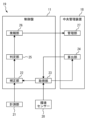
- FIG. 2 is a block diagram showing the configuration of the diagnostic system 19 according to the first embodiment.
- the diagnostic system 19 includes a correction unit 22, an acquisition unit 23, a calculation unit 24, a determination unit 25, and an alarm unit 26.
- the functions of the correction unit 22, the acquisition unit 23, the determination unit 25, and the alarm unit 26 are mounted on the control panel 11.
- the function of the calculation unit 24 is mounted on the central management device 18.
- the correction unit 22 is a part equipped with a function for correcting the door torque measurement value by the measurement unit 21 according to environmental information.
- the measurement unit 21 measures the door torque, for example, during a diagnostic operation.
- the correction unit 22 corrects the door torque measured at this time.
- the correction unit 22 corrects the door torque measurement value by adding an offset value according to the environmental information to the door torque measured by the measurement unit 21.
- the acquisition unit 23 is a part that has a function of acquiring an offset value that the correction unit 22 uses to correct the measurement value of the door torque.
- the acquisition unit 23 acquires environmental information when the measurement unit 21 measures the door torque.
- the acquisition unit 23 acquires environmental information when the measurement unit 21 measures the door torque, for example, from the environmental sensor 20.
- the acquisition unit 23 acquires environmental information during diagnostic operation, for example.
- the calculation unit 24 is a part equipped with a function for calculating an offset value based on environmental information.
- the calculation unit 24 receives environmental information from the acquisition unit 23.
- the calculation unit 24 outputs an offset value calculated based on the received environmental information to the acquisition unit 23.
- the offset value output by the calculation unit 24 is provided to the correction unit 22 via the acquisition unit 23.
- the determination unit 25 determines that the door torque is abnormal when the difference between the door torque value corrected by the correction unit 22 and the reference value is greater than a preset threshold value.
- the determination unit 25 uses, as the reference value, a measurement value measured by the measurement unit 21 when the elevator 1 is first started up after normality is confirmed after the elevator 1 is installed or after maintenance and inspection.
- environmental information when the door torque serving as the reference value is measured may be stored in the diagnosis system 19 together with the reference value.
- the temperature and humidity represented by the environmental information at this time are used as, for example, a reference temperature and reference humidity.
- the determination unit 25 may also use the door torque value corrected by the correction unit 22 based on the environmental information at this time as the reference value.
- the alarm unit 26 is a part equipped with a function for notifying the judgment result when the judgment unit 25 judges an abnormality in the door torque.
- the alarm unit 26 notifies the judgment result to the central management unit 18.
- the alarm from the alarm unit 26 is processed by the management unit 27, which manages information on the status of the elevator 1. Based on the alarm from the alarm unit 26, a response is made, such as dispatching a maintenance worker to the elevator 1 where the abnormality has occurred.
- FIG. 3 and FIG. 3 and 4 are diagrams showing examples of offset values in the diagnostic system 19 according to the first embodiment.
- the offset value depends on the difference between the environmental information when the reference door torque is measured and the environmental information when the door torque of the object to be diagnosed is measured. More specifically, the offset value depends on the difference between the reference temperature and the temperature when the door torque of the object to be diagnosed is measured. The offset value also depends on the difference between the reference humidity and the humidity when the door torque of the object to be diagnosed is measured.
- FIG. 3 an example of the relationship between the offset value and the temperature difference from the reference temperature is shown.
- the horizontal axis represents the temperature difference
- the vertical axis represents the offset value.
- the relationship between the offset value and the temperature difference may be either a linear relationship or a nonlinear relationship.
- the offset value may take either a continuous value or a discrete value with respect to the temperature difference.
- FIG. 4 an example of the relationship between the offset value and the humidity difference from the reference humidity is shown.
- the horizontal axis represents the humidity difference.
- the vertical axis represents the offset value.
- the relationship between the offset value and the humidity difference may be either a linear relationship or a nonlinear relationship.
- the offset value may take a continuous value or a discrete value with respect to the humidity difference.
- the relationship between the offset value and the environmental information may include an interaction that represents a synergistic effect of the temperature difference and the humidity difference.
- the calculation unit 24 calculates the offset value using the environmental information received from the acquisition unit 23, for example, based on the relationship shown in Figures 3 and 4.
- the relationship between the offset value and the environmental information is stored, for example, in the central management device 18 in which the calculation unit 24 is mounted.
- the relationship between the offset value and the environmental information is set, for example, based on a prior test or simulation.
- the relationship between the offset value and the environmental information may be set, for example, as follows, based on the measurement value in the elevator 1. Note that in this example, the relationship between the offset value and the environmental information is calculated in the calculation unit 24.
- the calculation unit 24 acquires, via the acquisition unit 23, the measurement value measured by the measurement unit 21 at the first start of the elevator 1 after the elevator 1 is confirmed to be normal after installation or after maintenance inspection, as a reference value. At this time, the calculation unit 24 also acquires environmental information at the time when the door torque serving as the reference value was measured. As a result, the calculation unit 24 acquires a combination of the reference value and the environmental information. The calculation unit 24 constructs a model representing the relationship between the reference value and the environmental information, for example, by simple regression or multiple regression, based on multiple combinations of the reference value and the environmental information.
- the calculation unit 24 may construct a model representing the relationship between the reference value and the environmental information, for example, by a method such as machine learning, based on multiple combinations of the reference value and the environmental information.
- the calculation unit 24 may also construct a model representing the relationship between the reference value and the environmental information by using the measurement values of other elevators of the elevator 1 in addition. At this time, the calculation unit 24 may also use only the measurement values of other elevators of the same model as the elevator 1 in addition.
- the calculation unit 24 sets the reference temperature and humidity as the reference operating environment, and sets the relationship between the offset value and the environmental information based on the difference between the reference door torque value in the reference operating environment and the reference door torque value in another operating environment.
- FIG. 5 is a flowchart showing an example of the operation of the diagnostic system 19 according to the first embodiment. The process in FIG. 5 is carried out, for example, during a diagnostic operation at a preset timing.
- step S101 the control panel 11 opens or closes the car door panel 14 using the door torque generated by the door drive device 13. At this time, the control panel 11 obtains a measurement value of the door torque from the measurement unit 21.
- the measurement unit 21 measures the value of the door torque generated by the door motor of the door drive device 13 for each certain opening degree between fully closed and fully open of the car door panel 14. In other words, the measurement unit 21 obtains the door torque at each opening degree of the car door panel 14 as a measurement value.
- the processing of the diagnosis system 19 proceeds to step S102.
- step S102 the control panel 11 acquires environmental information from the environmental sensor 20.
- the control panel 11 acquires information on the temperature and humidity of the elevator shaft 2 as the environmental information.
- the processing of the diagnostic system 19 proceeds to step S103.
- step S103 the acquisition unit 23 of the control panel 11 provides the environmental information acquired in step S102 to the calculation unit 24 of the central management unit 18. After that, the processing of the diagnostic system 19 proceeds to step S104.
- the calculation unit 24 calculates an offset value based on the temperature and humidity represented by the environmental information received from the acquisition unit 23. For example, the calculation unit 24 calculates the difference between the temperature and humidity represented by the environmental information and the temperature and humidity in the reference operating environment as a temperature difference and a humidity difference. Using the calculated temperature difference and humidity difference, the calculation unit 24 calculates an offset value based on, for example, the relationships shown in Figures 3 and 4. Here, when the measured value of the door torque is a value for each opening degree of the car door panel 14, the offset value may be set individually for each opening degree, or may be set as a single value averaged over each opening degree. The calculation unit 24 of the central management unit 18 outputs the calculated offset value to the acquisition unit 23 of the control panel 11.
- step S104 the acquisition unit 23 of the control panel 11 acquires the offset value from the calculation unit 24 of the central management unit 18. After that, the processing of the diagnostic system 19 proceeds to step S105.
- step S105 the correction unit 22 corrects the measurement value of the door torque acquired in step S101 with the offset value acquired in step S104.
- the correction unit 22 performs the correction by adding the offset value to the measurement value of the door torque.
- the measurement value of the door torque is a value for each opening degree of the car door panel 14, the correction unit 22 corrects the door torque for each opening degree.
- step S106 the judgment unit 25 performs a process of judging whether or not there is an abnormality in the door torque.
- the judgment unit 25 calculates the difference between the door torque value corrected in step S105 and a preset reference value.
- the reference value at this time is preset, for example, as a reference value in a reference operating environment.
- the judgment unit 25 judges the door torque abnormality when the calculated difference exceeds a preset threshold value.
- the judgment unit 25 calculates the difference from the reference value for each opening degree.
- the judgment unit 25 may judge the door torque abnormality when the difference exceeds a threshold value at any opening degree, or may judge the door torque abnormality when the sum of the differences of each opening degree or the sum of the absolute values of the differences exceeds a threshold value.
- the process of the diagnosis system 19 proceeds to step S107.
- the processing of the diagnostic system 19 ends.
- step S107 the alarm unit 26 of the control panel 11 notifies the management unit 27 of the central management unit 18 of the judgment result in step S106. Based on the notified content, the management unit 27 performs the necessary processing to respond, such as dispatching a maintenance worker to the elevator 1 where the abnormality has occurred. After that, the processing of the diagnosis system 19 ends.
- the diagnosis system 19 includes the measurement unit 21, the acquisition unit 23, the correction unit 22, and the determination unit 25.
- the measurement unit 21 measures the door torque when the door of the elevator 1 is opened or closed.
- the acquisition unit 23 acquires an offset value for correcting the measurement value of the door torque by the measurement unit 21 based on environmental information when the measurement unit 21 measures the door torque.
- the environmental information includes at least one of temperature and humidity information.
- the correction unit 22 corrects the measurement value of the door torque by the measurement unit 21 with the offset value acquired by the acquisition unit 23.
- the determination unit 25 judges an abnormality in the door torque when the difference between the door torque value corrected by the correction unit 22 and a preset reference value is greater than a preset threshold value.
- the diagnostic method includes a measurement step, an acquisition step, a correction step, and a judgment step.
- the measurement step is a step of measuring the door torque when the door of the elevator 1 is opened or closed.
- the acquisition step is a step of acquiring an offset value for correcting the measurement value of the door torque in the measurement step based on environmental information when the door torque is measured in the measurement step.
- the correction step is a step of correcting the measurement value of the door torque in the measurement step by the offset value acquired in the acquisition step.
- the judgment step is a step of judging an abnormality in the door torque when the difference between the door torque value corrected in the correction step and a preset reference value is greater than a preset threshold value.
- the measured value of the door torque is corrected using the offset value acquired based on the environmental information.
- An abnormality in the door torque of the elevator 1 is diagnosed based on the door torque corrected using the offset value. This allows the abnormality in the door torque of the elevator 1 to be diagnosed taking into account the effects of the operating environment.
- changes in physical properties such as dimensions and elasticity may occur due to temperature changes.
- changes in humidity may cause changes in the friction coefficient, etc.
- the door torque of the elevator 1 may be affected by the operating environment, such as temperature and humidity. Since the effects of the operating environment, such as temperature and humidity, are taken into account in the diagnostic system 19, the accuracy of the diagnosis is further improved.
- the diagnostic system 19 also includes an environmental sensor 20.
- the environmental sensor 20 is disposed in the elevator shaft 2 of the elevator 1.
- the environmental sensor 20 measures environmental information.
- the acquisition unit 23 acquires the environmental information from the environmental sensor 20.
- the door torque measurement value is corrected based on the environmental information actually measured in the elevator shaft 2. This allows the effects of the operating environment to be taken into account with greater accuracy, further improving the accuracy of diagnosis in the diagnostic system 19.
- the diagnostic system 19 also includes a calculation unit 24.
- the calculation unit 24 calculates an offset value based on the environmental information received from the acquisition unit 23.
- the acquisition unit 23 acquires the offset value from the calculation unit 24.
- the acquisition unit 23 may acquire the environmental information from an external weather information service.
- the external weather information service may be provided, for example, by a public institution or a weather business that handles weather information.
- the acquisition unit 23 acquires weather information for the location of the building to which the elevator 1 is applied, for example, via the communication network 17.
- the acquisition unit 23 acquires, for example, temperature and humidity information as the weather information.
- the acquisition unit 23 may acquire weather information such as sunny or rainy as the weather information.
- the acquisition unit 23 stores in advance environmental information corresponding to each piece of weather information, such as sunny or rainy, for example.
- the acquisition unit 23 acquires an offset value using the corresponding environmental information based on the acquired weather information.
- This configuration makes it possible to apply the diagnostic system 19 even when the elevator is not equipped with an environmental sensor.
- the calculation unit 24 may also be mounted on a computing device external to the diagnostic system 19.
- the computing device may be, for example, one or more server devices connected to the communication network 17.
- the central management device 18 may be an external device included in a different system separated from the diagnostic system 19.
- the central management device 18 equipped with functions such as the calculation unit 24 is an example of a computing device external to the diagnostic system 19.
- Some or all of the functions of the diagnostic system 19, such as the correction unit 22, the acquisition unit 23, the determination unit 25, and the alarm unit 26, may also be mounted on the control panel 11, the remote monitoring device 16, and the central management device 18, as well as other devices of the elevator 1.
- the diagnostic system 19 may also perform diagnosis during normal operation of the elevator 1. For example, the diagnostic system 19 may diagnose whether or not there is an abnormality in the door torque each time the car door panel 14 is opened or closed during normal operation.
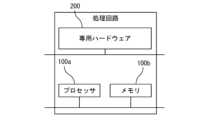
- FIG. 6 is a hardware configuration diagram of a main part of the diagnostic system 19 according to the first embodiment.
- Each processing function in the diagnostic system 19 may be realized by a processing circuit.
- the processing circuit includes at least one processor 100a and at least one memory 100b.
- the processing circuit may include at least one dedicated hardware 200 in addition to or in place of the processor 100a and memory 100b.
- each function of the diagnostic system 19 is realized by software, firmware, or a combination of software and firmware. At least one of the software and firmware is written as a program. The program is stored in the memory 100b. The processor 100a realizes each function of the diagnostic system 19 by reading and executing the program stored in the memory 100b.
- the processor 100a is also called a CPU (Central Processing Unit), processing device, arithmetic unit, microprocessor, microcomputer, or DSP.
- the memory 100b is composed of non-volatile or volatile semiconductor memory such as RAM, ROM, flash memory, EPROM, and EEPROM.
- processing circuitry comprises dedicated hardware 200
- the processing circuitry may be implemented, for example, as a single circuit, a composite circuit, a programmed processor, a parallel programmed processor, an ASIC, an FPGA, or a combination thereof.
- Each processing function in diagnostic system 19 can be realized by a processing circuit. Alternatively, each function of diagnostic system 19 can be realized collectively by a processing circuit. Some of the functions of diagnostic system 19 may be realized by dedicated hardware 200, and other parts may be realized by software or firmware. In this way, the processing circuit realizes each function of diagnostic system 19 by dedicated hardware 200, software, firmware, or a combination of these.
- the content output system disclosed herein can be applied to elevators.
Landscapes
- Engineering & Computer Science (AREA)
- Automation & Control Theory (AREA)
- Indicating And Signalling Devices For Elevators (AREA)
- Maintenance And Inspection Apparatuses For Elevators (AREA)
- Elevator Door Apparatuses (AREA)
Priority Applications (2)
| Application Number | Priority Date | Filing Date | Title |
|---|---|---|---|
| PCT/JP2022/039289 WO2024084684A1 (ja) | 2022-10-21 | 2022-10-21 | エレベーターの診断システムおよび診断方法 |
| JP2024551177A JPWO2024084684A1 (https=) | 2022-10-21 | 2022-10-21 |
Applications Claiming Priority (1)
| Application Number | Priority Date | Filing Date | Title |
|---|---|---|---|
| PCT/JP2022/039289 WO2024084684A1 (ja) | 2022-10-21 | 2022-10-21 | エレベーターの診断システムおよび診断方法 |
Publications (1)
| Publication Number | Publication Date |
|---|---|
| WO2024084684A1 true WO2024084684A1 (ja) | 2024-04-25 |
Family
ID=90737204
Family Applications (1)
| Application Number | Title | Priority Date | Filing Date |
|---|---|---|---|
| PCT/JP2022/039289 Ceased WO2024084684A1 (ja) | 2022-10-21 | 2022-10-21 | エレベーターの診断システムおよび診断方法 |
Country Status (2)
| Country | Link |
|---|---|
| JP (1) | JPWO2024084684A1 (https=) |
| WO (1) | WO2024084684A1 (https=) |
Citations (6)
| Publication number | Priority date | Publication date | Assignee | Title |
|---|---|---|---|---|
| JP2011063404A (ja) * | 2009-09-18 | 2011-03-31 | Toshiba Elevator Co Ltd | エレベータのドア制御装置 |
| JP2012240789A (ja) * | 2011-05-19 | 2012-12-10 | Toshiba Elevator Co Ltd | エレベーターのドア制御装置 |
| JP2013170031A (ja) * | 2012-02-20 | 2013-09-02 | Toshiba Elevator Co Ltd | エレベータドアの遠隔点検オペレーションシステム |
| JP2016074531A (ja) * | 2014-10-08 | 2016-05-12 | 株式会社日立ビルシステム | エレベーターの点検装置 |
| WO2022091376A1 (ja) * | 2020-10-30 | 2022-05-05 | 三菱電機ビルテクノサービス株式会社 | エレベーターの故障診断装置 |
| WO2022219820A1 (ja) * | 2021-04-16 | 2022-10-20 | 三菱電機ビルソリューションズ株式会社 | エレベーターのモータの異常検出システム |
-
2022
- 2022-10-21 JP JP2024551177A patent/JPWO2024084684A1/ja active Pending
- 2022-10-21 WO PCT/JP2022/039289 patent/WO2024084684A1/ja not_active Ceased
Patent Citations (6)
| Publication number | Priority date | Publication date | Assignee | Title |
|---|---|---|---|---|
| JP2011063404A (ja) * | 2009-09-18 | 2011-03-31 | Toshiba Elevator Co Ltd | エレベータのドア制御装置 |
| JP2012240789A (ja) * | 2011-05-19 | 2012-12-10 | Toshiba Elevator Co Ltd | エレベーターのドア制御装置 |
| JP2013170031A (ja) * | 2012-02-20 | 2013-09-02 | Toshiba Elevator Co Ltd | エレベータドアの遠隔点検オペレーションシステム |
| JP2016074531A (ja) * | 2014-10-08 | 2016-05-12 | 株式会社日立ビルシステム | エレベーターの点検装置 |
| WO2022091376A1 (ja) * | 2020-10-30 | 2022-05-05 | 三菱電機ビルテクノサービス株式会社 | エレベーターの故障診断装置 |
| WO2022219820A1 (ja) * | 2021-04-16 | 2022-10-20 | 三菱電機ビルソリューションズ株式会社 | エレベーターのモータの異常検出システム |
Also Published As
| Publication number | Publication date |
|---|---|
| JPWO2024084684A1 (https=) | 2024-04-25 |
Similar Documents
| Publication | Publication Date | Title |
|---|---|---|
| US7823706B2 (en) | Condition monitoring system | |
| CN100349791C (zh) | 电梯的遥测方法和装置 | |
| CN101269767A (zh) | 电梯的维护管理系统 | |
| CN112840141B (zh) | 电梯的制动装置劣化预测系统 | |
| WO2014199688A1 (ja) | ドア装置およびドアの制御方法 | |
| JP6565781B2 (ja) | エレベーターの戸開閉診断システム | |
| JP7197059B2 (ja) | エレベーターシステム及び検査端末 | |
| JP7284735B2 (ja) | エレベータ診断装置、および、エレベータ診断方法 | |
| JP2009040586A (ja) | エレベータのロープ診断システム | |
| EP3363758A1 (en) | Mechanism for monitoring operation of passenger transport device | |
| JP2771454B2 (ja) | エレベーターの走行性能診断装置 | |
| CN116348406B (zh) | 电梯的故障诊断装置 | |
| WO2024084684A1 (ja) | エレベーターの診断システムおよび診断方法 | |
| JP5535441B2 (ja) | エレベータの管制運転装置 | |
| JP2007070102A (ja) | エレベータドアの診断装置 | |
| WO2021144932A1 (ja) | エレベーターの判定装置 | |
| JP4804777B2 (ja) | エレベータ装置 | |
| WO2024042642A1 (ja) | エレベーターのガイドレールの変形検出システムおよび変形検出方法 | |
| KR102529746B1 (ko) | 엘리베이터의 도어의 상황 검지 장치의 검지 상태를 진단하는 진단 시스템 | |
| JP7612925B1 (ja) | エレベータのロープ診断装置およびエレベータのロープ診断方法 | |
| JP2017057057A (ja) | エレベータードア異常診断装置、エレベータードア異常診断方法及びエレベーターシステム | |
| JP7392892B1 (ja) | エレベーターのドア制御装置 | |
| JP6893442B2 (ja) | エレベーターシステム | |
| JP2026033904A (ja) | カウンタークリアランス測定システム、それを備えたエレベータシステム、および、カウンタークリアランス測定方法 | |
| JP2021130516A (ja) | エレベーター診断装置、エレベーターの荷重検出装置の診断方法及びエレベーターシステム |
Legal Events
| Date | Code | Title | Description |
|---|---|---|---|
| 121 | Ep: the epo has been informed by wipo that ep was designated in this application |
Ref document number: 22962791 Country of ref document: EP Kind code of ref document: A1 |
|
| WWE | Wipo information: entry into national phase |
Ref document number: 2024551177 Country of ref document: JP |
|
| NENP | Non-entry into the national phase |
Ref country code: DE |
|
| 122 | Ep: pct application non-entry in european phase |
Ref document number: 22962791 Country of ref document: EP Kind code of ref document: A1 |