WO2024075592A1 - 基板処理システム、および搬送方法 - Google Patents
基板処理システム、および搬送方法 Download PDFInfo
- Publication number
- WO2024075592A1 WO2024075592A1 PCT/JP2023/034920 JP2023034920W WO2024075592A1 WO 2024075592 A1 WO2024075592 A1 WO 2024075592A1 JP 2023034920 W JP2023034920 W JP 2023034920W WO 2024075592 A1 WO2024075592 A1 WO 2024075592A1
- Authority
- WO
- WIPO (PCT)
- Prior art keywords
- ring
- temperature
- temperature adjustment
- replacement
- substrate
- Prior art date
- Legal status (The legal status is an assumption and is not a legal conclusion. Google has not performed a legal analysis and makes no representation as to the accuracy of the status listed.)
- Ceased
Links
Images

Classifications
-
- H—ELECTRICITY
- H10—SEMICONDUCTOR DEVICES; ELECTRIC SOLID-STATE DEVICES NOT OTHERWISE PROVIDED FOR
- H10P—GENERIC PROCESSES OR APPARATUS FOR THE MANUFACTURE OR TREATMENT OF DEVICES COVERED BY CLASS H10
- H10P72/00—Handling or holding of wafers, substrates or devices during manufacture or treatment thereof
- H10P72/04—Apparatus for manufacture or treatment
- H10P72/0451—Apparatus for manufacturing or treating in a plurality of work-stations
- H10P72/0452—Apparatus for manufacturing or treating in a plurality of work-stations characterised by the layout of the process chambers
- H10P72/0454—Apparatus for manufacturing or treating in a plurality of work-stations characterised by the layout of the process chambers surrounding a central transfer chamber
-
- H—ELECTRICITY
- H01—ELECTRIC ELEMENTS
- H01J—ELECTRIC DISCHARGE TUBES OR DISCHARGE LAMPS
- H01J37/00—Discharge tubes with provision for introducing objects or material to be exposed to the discharge, e.g. for the purpose of examination or processing thereof
- H01J37/32—Gas-filled discharge tubes
- H01J37/32431—Constructional details of the reactor
- H01J37/32715—Workpiece holder
-
- H—ELECTRICITY
- H01—ELECTRIC ELEMENTS
- H01J—ELECTRIC DISCHARGE TUBES OR DISCHARGE LAMPS
- H01J37/00—Discharge tubes with provision for introducing objects or material to be exposed to the discharge, e.g. for the purpose of examination or processing thereof
- H01J37/32—Gas-filled discharge tubes
- H01J37/32431—Constructional details of the reactor
- H01J37/32623—Mechanical discharge control means
- H01J37/32642—Focus rings
-
- H—ELECTRICITY
- H01—ELECTRIC ELEMENTS
- H01J—ELECTRIC DISCHARGE TUBES OR DISCHARGE LAMPS
- H01J37/00—Discharge tubes with provision for introducing objects or material to be exposed to the discharge, e.g. for the purpose of examination or processing thereof
- H01J37/32—Gas-filled discharge tubes
- H01J37/32431—Constructional details of the reactor
- H01J37/32715—Workpiece holder
- H01J37/32724—Temperature
-
- H—ELECTRICITY
- H01—ELECTRIC ELEMENTS
- H01J—ELECTRIC DISCHARGE TUBES OR DISCHARGE LAMPS
- H01J37/00—Discharge tubes with provision for introducing objects or material to be exposed to the discharge, e.g. for the purpose of examination or processing thereof
- H01J37/32—Gas-filled discharge tubes
- H01J37/32431—Constructional details of the reactor
- H01J37/32798—Further details of plasma apparatus not provided for in groups H01J37/3244 - H01J37/32788; special provisions for cleaning or maintenance of the apparatus
- H01J37/32807—Construction (includes replacing parts of the apparatus)
-
- H—ELECTRICITY
- H01—ELECTRIC ELEMENTS
- H01J—ELECTRIC DISCHARGE TUBES OR DISCHARGE LAMPS
- H01J37/00—Discharge tubes with provision for introducing objects or material to be exposed to the discharge, e.g. for the purpose of examination or processing thereof
- H01J37/32—Gas-filled discharge tubes
- H01J37/32431—Constructional details of the reactor
- H01J37/32798—Further details of plasma apparatus not provided for in groups H01J37/3244 - H01J37/32788; special provisions for cleaning or maintenance of the apparatus
- H01J37/3288—Maintenance
-
- H—ELECTRICITY
- H01—ELECTRIC ELEMENTS
- H01J—ELECTRIC DISCHARGE TUBES OR DISCHARGE LAMPS
- H01J37/00—Discharge tubes with provision for introducing objects or material to be exposed to the discharge, e.g. for the purpose of examination or processing thereof
- H01J37/32—Gas-filled discharge tubes
- H01J37/32431—Constructional details of the reactor
- H01J37/32798—Further details of plasma apparatus not provided for in groups H01J37/3244 - H01J37/32788; special provisions for cleaning or maintenance of the apparatus
- H01J37/32889—Connection or combination with other apparatus
-
- H—ELECTRICITY
- H10—SEMICONDUCTOR DEVICES; ELECTRIC SOLID-STATE DEVICES NOT OTHERWISE PROVIDED FOR
- H10P—GENERIC PROCESSES OR APPARATUS FOR THE MANUFACTURE OR TREATMENT OF DEVICES COVERED BY CLASS H10
- H10P50/00—Etching of wafers, substrates or parts of devices
- H10P50/20—Dry etching; Plasma etching; Reactive-ion etching
- H10P50/24—Dry etching; Plasma etching; Reactive-ion etching of semiconductor materials
- H10P50/242—Dry etching; Plasma etching; Reactive-ion etching of semiconductor materials of Group IV materials
-
- H—ELECTRICITY
- H10—SEMICONDUCTOR DEVICES; ELECTRIC SOLID-STATE DEVICES NOT OTHERWISE PROVIDED FOR
- H10P—GENERIC PROCESSES OR APPARATUS FOR THE MANUFACTURE OR TREATMENT OF DEVICES COVERED BY CLASS H10
- H10P72/00—Handling or holding of wafers, substrates or devices during manufacture or treatment thereof
- H10P72/04—Apparatus for manufacture or treatment
- H10P72/0431—Apparatus for thermal treatment
-
- H—ELECTRICITY
- H10—SEMICONDUCTOR DEVICES; ELECTRIC SOLID-STATE DEVICES NOT OTHERWISE PROVIDED FOR
- H10P—GENERIC PROCESSES OR APPARATUS FOR THE MANUFACTURE OR TREATMENT OF DEVICES COVERED BY CLASS H10
- H10P72/00—Handling or holding of wafers, substrates or devices during manufacture or treatment thereof
- H10P72/06—Apparatus for monitoring, sorting, marking, testing or measuring
- H10P72/0606—Position monitoring, e.g. misposition detection or presence detection
-
- H—ELECTRICITY
- H10—SEMICONDUCTOR DEVICES; ELECTRIC SOLID-STATE DEVICES NOT OTHERWISE PROVIDED FOR
- H10P—GENERIC PROCESSES OR APPARATUS FOR THE MANUFACTURE OR TREATMENT OF DEVICES COVERED BY CLASS H10
- H10P72/00—Handling or holding of wafers, substrates or devices during manufacture or treatment thereof
- H10P72/30—Handling or holding of wafers, substrates or devices during manufacture or treatment thereof for conveying, e.g. between different workstations
-
- H—ELECTRICITY
- H10—SEMICONDUCTOR DEVICES; ELECTRIC SOLID-STATE DEVICES NOT OTHERWISE PROVIDED FOR
- H10P—GENERIC PROCESSES OR APPARATUS FOR THE MANUFACTURE OR TREATMENT OF DEVICES COVERED BY CLASS H10
- H10P72/00—Handling or holding of wafers, substrates or devices during manufacture or treatment thereof
- H10P72/30—Handling or holding of wafers, substrates or devices during manufacture or treatment thereof for conveying, e.g. between different workstations
- H10P72/33—Handling or holding of wafers, substrates or devices during manufacture or treatment thereof for conveying, e.g. between different workstations into and out of processing chamber
- H10P72/3302—Mechanical parts of transfer devices
-
- H—ELECTRICITY
- H10—SEMICONDUCTOR DEVICES; ELECTRIC SOLID-STATE DEVICES NOT OTHERWISE PROVIDED FOR
- H10P—GENERIC PROCESSES OR APPARATUS FOR THE MANUFACTURE OR TREATMENT OF DEVICES COVERED BY CLASS H10
- H10P72/00—Handling or holding of wafers, substrates or devices during manufacture or treatment thereof
- H10P72/30—Handling or holding of wafers, substrates or devices during manufacture or treatment thereof for conveying, e.g. between different workstations
- H10P72/34—Handling or holding of wafers, substrates or devices during manufacture or treatment thereof for conveying, e.g. between different workstations the wafers being stored in a carrier, involving loading and unloading
- H10P72/3404—Storage means
-
- H—ELECTRICITY
- H10—SEMICONDUCTOR DEVICES; ELECTRIC SOLID-STATE DEVICES NOT OTHERWISE PROVIDED FOR
- H10P—GENERIC PROCESSES OR APPARATUS FOR THE MANUFACTURE OR TREATMENT OF DEVICES COVERED BY CLASS H10
- H10P72/00—Handling or holding of wafers, substrates or devices during manufacture or treatment thereof
- H10P72/50—Handling or holding of wafers, substrates or devices during manufacture or treatment thereof for positioning, orientation or alignment
-
- H—ELECTRICITY
- H10—SEMICONDUCTOR DEVICES; ELECTRIC SOLID-STATE DEVICES NOT OTHERWISE PROVIDED FOR
- H10P—GENERIC PROCESSES OR APPARATUS FOR THE MANUFACTURE OR TREATMENT OF DEVICES COVERED BY CLASS H10
- H10P72/00—Handling or holding of wafers, substrates or devices during manufacture or treatment thereof
- H10P72/50—Handling or holding of wafers, substrates or devices during manufacture or treatment thereof for positioning, orientation or alignment
- H10P72/53—Handling or holding of wafers, substrates or devices during manufacture or treatment thereof for positioning, orientation or alignment using optical controlling means
-
- H—ELECTRICITY
- H10—SEMICONDUCTOR DEVICES; ELECTRIC SOLID-STATE DEVICES NOT OTHERWISE PROVIDED FOR
- H10P—GENERIC PROCESSES OR APPARATUS FOR THE MANUFACTURE OR TREATMENT OF DEVICES COVERED BY CLASS H10
- H10P72/00—Handling or holding of wafers, substrates or devices during manufacture or treatment thereof
- H10P72/70—Handling or holding of wafers, substrates or devices during manufacture or treatment thereof for supporting or gripping
- H10P72/76—Handling or holding of wafers, substrates or devices during manufacture or treatment thereof for supporting or gripping using mechanical means, e.g. clamps or pinches
- H10P72/7604—Handling or holding of wafers, substrates or devices during manufacture or treatment thereof for supporting or gripping using mechanical means, e.g. clamps or pinches the wafers being placed on a susceptor, stage or support
- H10P72/7611—Handling or holding of wafers, substrates or devices during manufacture or treatment thereof for supporting or gripping using mechanical means, e.g. clamps or pinches the wafers being placed on a susceptor, stage or support characterised by edge profile or support profile
Definitions
- This disclosure relates to a substrate processing system and a transport method.
- Patent Document 1 discloses a substrate processing system that performs substrate processing (plasma processing) by arranging a focus ring around a mounting table (substrate support portion) on which a substrate is placed.
- this substrate processing system performs the following operations: a transport device removes the focus ring from the processing chamber, a cleaning process is performed on the surface of the mounting table on which the focus ring is placed, and the transport device transports the focus ring into the processing chamber.
- This disclosure provides technology that can improve the productivity of substrate processing.
- a substrate processing system including a processing module having a processing chamber, a substrate support portion including a substrate support surface and a ring support surface that is disposed within the processing chamber and surrounds the substrate support surface and supports a ring, a vacuum transfer module connected to the processing module and having a transfer robot that transfers the ring, a temperature adjustment portion capable of adjusting the temperature of the ring, and a control portion, in which the control portion performs, in this order, a step of adjusting the temperature of the ring using the temperature adjustment portion before the ring is carried into the processing module, and a step of transporting the ring, whose temperature has been adjusted by the temperature adjustment portion, using the transfer robot to place it on the substrate support portion.
- the productivity of substrate processing can be improved.
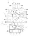
- FIG. 1 is a diagram illustrating an example of a substrate processing system according to an embodiment.
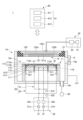
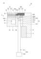
- 1 is a schematic cross-sectional view showing an example of a plasma processing apparatus.
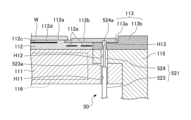
- FIG. 3 is an enlarged view of a portion of FIG. 2 .
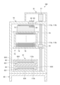
- FIG. 1 is a first schematic side cross-sectional view showing a ring storage module.
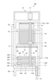
- 5 is a second schematic cross-sectional side view of the ring storage module as viewed in a direction perpendicular to FIG. 4.
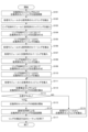
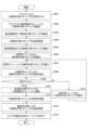
- 4 is a flowchart showing a first example of a conveying method.
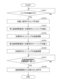
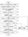
- 13 is a flowchart showing an example of a procedure of step S101.
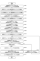
- 10 is a flowchart showing a conveying method according to a second example.
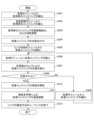
- 13 is a flowchart showing a conveying method according to a third example.
- FIG. 13 is an enlarged view showing a part of a plasma processing apparatus according to another embodiment.
- FIG. 13 illustrates an example of a substrate processing system according to another embodiment.
- 13 is a flowchart showing a conveying method according to a fourth example.
- 13 is a flowchart showing a conveying method according to a fifth example.
- FIG. 1 is a diagram showing an example of a substrate processing system PS according to an embodiment.
- the substrate processing system PS is a system capable of performing various processes, such as plasma processing, on a substrate W.
- the substrate W may be, for example, a semiconductor wafer.
- the substrate processing system PS has a vacuum transfer module TM, multiple processing modules PM1 to PM7, a ring storage module RSM, multiple load lock modules LL1 to LL3, an atmospheric transfer module LM, load ports LP1 to LP4, an aligner AN, and a control unit CU.
- the vacuum transfer module TM is also called a transfer module.
- the processing modules PM1 to PM7 are also called process modules.
- the ring storage module RSM is also called a ring stocker module.
- the atmospheric transfer module LM is also called a loader module.
- the vacuum transfer module TM has a rectangular shape in a plan view.
- the vacuum transfer module TM is connected to the processing modules PM1 to PM7, the load lock modules LL1 to LL3, and the ring storage module RSM.
- the vacuum transfer module TM has a vacuum transfer chamber. The interior of the vacuum transfer chamber is maintained in a vacuum atmosphere.
- a transfer robot TR1 is provided in the vacuum transfer chamber (inside the vacuum transfer module TM).
- the transport robot TR1 is configured to be able to rotate, extend, retract, and rise and fall freely.
- the transport robot TR1 has an upper fork FK1 and a lower fork FK2.
- the upper fork FK1 and the lower fork FK2 of the transport robot TR1 are configured to be able to hold substrates W and rings 113 (inner ring 113a and outer ring 113b), respectively.
- the transport robot TR1 holds and transports substrates W and rings 113 between the processing modules PM1-PM7, the load lock modules LL1-LL3, and the ring storage module RSM.
- the upper fork FK1 is provided with a position detection sensor S1.
- the lower fork FK2 is provided with a position detection sensor S2.
- the position detection sensors S1 and S2 detect the positions of the inner ring 113a and the outer ring 113b placed on the processing modules PM1 to PM7.
- the position detection sensors S1 and S2 may be, for example, optical displacement sensors, cameras, etc.
- the vacuum transport module TM may be provided with position detection sensors S11 and S12.
- the position detection sensors S11 and S12 are provided on the transport path of the substrate W and ring 113 (inner ring 113a) transported from the vacuum transport module TM to the processing module PM1.
- the position detection sensors S11 and S12 are used when transporting the substrate W or ring 113 from the vacuum transport module TM to the processing module PM1, and when transporting the substrate W or ring 113 from the processing module PM1 to the vacuum transport module TM.
- the position detection sensors S11 and S12 are provided, for example, near a gate valve (not shown) that separates the vacuum transport module TM and the processing module PM1.
- the position detection sensors S11 and S12 are arranged, for example, so that the distance between them is smaller than the outer diameter of the substrate W and smaller than the inner diameter of the inner ring 113a.
- the vacuum transfer module TM may be provided with position detection sensors S21, S22, S31, S32, S41, S42, S51, S52, S61, S62, S71, and S72, as well as position detection sensors S11 and S12.
- the processing modules PM1 to PM7 are connected to a vacuum transfer module TM.
- the processing modules PM1 to PM7 have a vacuum processing chamber.
- a substrate support 11 (see Figure 2) is provided inside the vacuum processing chamber. After a substrate W is placed on the substrate support 11, the processing modules PM1 to PM7 reduce the pressure inside, introduce a processing gas, apply RF power to generate plasma, and use the plasma to perform plasma processing on the substrate W.
- the vacuum transfer module TM and the processing modules PM1 to PM7 are separated by a gate valve (not shown) that can be opened and closed freely.
- the ring storage module RSM is an example of a device that stores the ring 113, and is connected to the vacuum transfer module TM.
- the ring storage module RSM stores, for example, the inner ring 113a and the outer ring 113b that make up the ring 113.
- the ring storage module RSM may be configured to store only the inner ring 113a.
- the ring storage module RSM may be configured to store only the outer ring 113b.
- the inner ring 113a and the outer ring 113b are transported between the processing modules PM1 to PM7 and the ring storage module RSM by the transport robot TR1.
- the vacuum transfer module TM and the ring storage module RSM are separated by a gate valve G (see Figure 5) that can be opened and closed freely.
- the load lock modules LL1 to LL3 are provided between the vacuum transfer module TM and the atmospheric transfer module LM.
- the load lock modules LL1 to LL3 are connected to the vacuum transfer module TM and the atmospheric transfer module LM.
- the load lock modules LL1 to LL3 have an internal pressure variable chamber that can be switched between vacuum and atmospheric pressure.
- the internal pressure variable chamber is provided with a stage (not shown) on which a substrate W can be placed.
- the load lock modules LL1 to LL3 transfer a substrate W from the vacuum transfer module TM to the atmospheric transfer module LM, they receive the substrate W from the vacuum transfer module TM while maintaining the internal pressure variable chamber at a vacuum, and then they pressurize the internal pressure variable chamber to atmospheric pressure and transfer the substrate W to the atmospheric transfer module LM.
- the load lock modules LL1 to LL3 and the vacuum transfer module TM are separated by a gate valve (not shown) that can be opened and closed.
- the load lock modules LL1 to LL3 and the atmospheric transfer module LM are separated by a gate valve (not shown) that can be opened and closed.
- the atmospheric transfer module LM is provided opposite the vacuum transfer module TM.
- the atmospheric transfer module LM may be, for example, an EFEM (Equipment Front End Module).
- the atmospheric transfer module LM has a rectangular shape in a plan view.
- the atmospheric transfer module LM has an atmospheric transfer chamber. The interior of the atmospheric transfer chamber is maintained at atmospheric pressure.
- a transfer robot TR2 is provided inside the atmospheric transfer chamber.
- the transfer robot TR2 is configured to be able to rotate, expand and contract, and move up and down freely.
- the transfer robot TR2 also has two forks (upper fork and lower fork) that can hold and transport a substrate W.
- the transfer robot TR2 holds and transports a substrate W between the load ports LP1 to LP4, the aligner AN, and the load lock modules LL1 to LL3.
- the atmospheric transfer module LM may have an FFU (Fan Filter Unit).
- the load ports LP1 to LP4 are connected to an atmospheric transfer module LM.
- Multiple substrate storage containers CS1 are placed on the load ports LP1 to LP4.
- the substrate storage container CS1 may be, for example, a FOUP (Front-Opening Unified Pod) that stores multiple (e.g., 25) substrates W.
- FOUP Front-Opening Unified Pod
- the aligner AN is connected to the atmospheric transfer module LM.
- the aligner AN is configured to adjust the position of the substrate W.
- the aligner AN may be provided inside the atmospheric transfer chamber.
- the control unit CU controls each part of the substrate processing system PS.
- the control unit CU controls, for example, the operation of the transport robot TR1 provided in the vacuum transport module TM, the operation of the transport robot TR2 provided in the atmospheric transport module LM, and the opening and closing of the gate valve.
- the control unit CU may be, for example, a computer.
- the control unit CU has a processor such as a CPU (Central Processing Unit), RAM (Random Access Memory), ROM (Read Only Memory), and an auxiliary storage device.
- the CPU operates based on a program stored in the ROM or the auxiliary storage device, and controls each part of the substrate processing system PS.
- FIG. 2 is a schematic cross-sectional view showing the example of the plasma processing apparatus 1.
- Fig. 3 is an enlarged view of a part of Fig. 2.
- the plasma processing apparatus 1 includes a plasma processing chamber 10, a gas supply unit 20, an RF power supply unit 30, an exhaust system 40, a lifter 50, and a control unit 90.
- the plasma processing chamber 10 includes a substrate support 11 and an upper electrode 12.
- the substrate support 11 is disposed in a lower region of the plasma processing space 10s in the plasma processing chamber 10.
- the upper electrode 12 is disposed above the substrate support 11 and functions as part of the top plate of the plasma processing chamber 10.
- the substrate support part 11 supports the substrate W in the plasma processing space 10s.
- the substrate support part 11 includes a lower electrode 111, an electrostatic chuck 112, a ring 113 (hereinafter also referred to as the ring assembly 113), and an insulating member 115.
- the substrate support part 11 also includes a support part temperature adjustment mechanism 116 that adjusts the temperature of the supported substrate W and ring 113.
- the electrostatic chuck 112 is disposed on the lower electrode 111.
- the electrostatic chuck 112 has an upper surface including a substrate support surface 112a and a ring support surface 112b.
- the electrostatic chuck 112 supports the substrate W on the substrate support surface 112a.
- the electrostatic chuck 112 supports the inner ring 113a on the ring support surface 112b.
- the electrostatic chuck 112 has an insulating member 112c, a first adsorption electrode 112d, and a second adsorption electrode 112e.
- the first adsorption electrode 112d and the second adsorption electrode 112e are embedded in the insulating member 112c.
- the first adsorption electrode 112d is located below the substrate support surface 112a.
- the electrostatic chuck 112 adsorbs and holds the substrate W on the substrate support surface 112a by applying a voltage to the first adsorption electrode 112d.
- the second adsorption electrode 112e is located below the ring support surface 112b.
- the electrostatic chuck 112 attracts and holds the inner ring 113a on the ring support surface 112b by applying a voltage to the second attraction electrode 112e.
- the electrostatic chuck 112 includes a monopolar electrostatic chuck that attracts and holds the substrate W, and a bipolar electrostatic chuck that attracts and holds the inner ring 113a.
- a bipolar electrostatic chuck may be used instead of the monopolar electrostatic chuck, and a monopolar electrostatic chuck may be used instead of the bipolar electrostatic chuck.
- the ring assembly 113 includes an inner ring 113a and an outer ring 113b.
- the inner ring 113a has a circular ring shape.
- the inner ring 113a is arranged around the substrate W on the upper peripheral surface of the lower electrode 111.
- the inner ring 113a improves the uniformity of the plasma processing on the substrate W.
- the inner ring 113a is formed of a conductive material such as silicon (Si) or silicon carbide (SiC).
- the inner ring 113a may be formed of an insulating material such as quartz.
- the outer ring 113b has a circular ring shape.
- the outer ring 113b is arranged on the outer periphery of the inner ring 113a.
- the outer ring 113b protects the upper surface of the insulating member 115 from, for example, plasma.
- the outer ring 113b is formed of an insulating material such as quartz.
- the outer ring 113b may be formed of a conductive material such as silicon or silicon carbide.
- the inner circumference of the outer ring 113b is located inside the outer circumference of the inner ring 113a, and the outer circumference of the inner ring 113a is located outside the inner circumference of the outer ring 113b, so that the inner ring 113a and the outer ring 113b partially overlap.
- the outer ring 113b is provided so as to surround the inner ring 113a and overlap the inner ring 113a below in a plan view.
- the insulating member 115 is disposed so as to surround the lower electrode 111.
- the insulating member 115 is fixed to the bottom of the plasma processing chamber 10 and supports the lower electrode 111.
- the support temperature adjustment mechanism 116 adjusts the temperature of the substrate W and the ring assembly 113 together.
- the support temperature adjustment mechanism 116 is provided inside the electrostatic chuck 112 (or inside the lower electrode 111 or the insulating member 115).
- the support temperature adjustment mechanism 116 can be, for example, a heater, a structure that circulates a heat exchange medium from a heat exchange medium circulation unit (not shown), or a structure that supplies a heat transfer gas from a gas supply and exhaust unit (not shown).
- the upper electrode 12 and the insulating member 13 constitute the plasma processing chamber 10.
- the upper electrode 12 supplies one or more types of processing gas from the gas supply unit 20 to the plasma processing space 10s.
- the upper electrode 12 includes a top plate 121 and a support 122.
- the lower surface of the top plate 121 defines the plasma processing space 10s.
- the top plate 121 is provided with a plurality of gas inlets 121a. Each of the plurality of gas inlets 121a penetrates the top plate 121 in the plate thickness direction (vertical direction).
- the support 122 supports the top plate 121 in a removable manner.
- a gas diffusion chamber 122a is provided inside the support 122.
- a plurality of gas inlets 122b extend downward from the gas diffusion chamber 122a.
- the plurality of gas inlets 122b are each connected to the plurality of gas inlets 121a.
- the support 122 is provided with a gas supply port 122c.
- the upper electrode 12 supplies one or more processing gases from the gas supply port 122c through the gas diffusion chamber 122a, the multiple gas inlets 122b, and the multiple gas inlets 121a to the plasma processing space 10s.
- a loading/unloading port 10p is provided on the side wall of the plasma processing chamber 10.
- the substrate W is transported between the plasma processing space 10s and the outside of the plasma processing chamber 10 via the loading/unloading port 10p.
- the loading/unloading port 10p is opened and closed by a gate valve G.
- the gas supply unit 20 includes one or more gas sources 21 and one or more flow controllers 22.
- the gas supply unit 20 supplies one or more types of process gas from each gas source 21 to the gas supply port 122c via each flow controller 22.
- the flow controller 22 may include, for example, a mass flow controller or a pressure-controlled flow controller.
- the gas supply unit 20 may include one or more flow modulation devices that modulate or pulse the flow rate of one or more process gases.
- the RF power supply unit 30 includes two RF power sources (first RF power source 31a, second RF power source 31b) and two matchers (first matcher 32a, second matcher 32b).
- the first RF power source 31a supplies the first RF power to the lower electrode 111 via the first matcher 32a.
- the frequency of the first RF power may be, for example, 13 MHz to 150 MHz.
- the second RF power source 31b supplies the second RF power to the lower electrode 111 via the second matcher 32b.
- the frequency of the second RF power may be, for example, 400 kHz to 13.56 MHz.
- a DC power source may be used instead of the second RF power source 31b.
- the exhaust system 40 is connected to a gas exhaust port 10e provided, for example, at the bottom of the plasma processing chamber 10.
- the exhaust system 40 may include a pressure regulating valve and a vacuum pump.
- the pressure in the plasma processing space 10s is adjusted by the pressure regulating valve.
- the vacuum pump may include a turbomolecular pump, a dry pump, or a combination thereof.
- the lifter 50 includes a first lifter 51 and a second lifter 52.
- the first lifter 51 includes a plurality of support pins 511 and an actuator 512.
- the plurality of support pins 511 are inserted into through holes H1 formed in the lower electrode 111 and the electrostatic chuck 112, and can be protruded and retracted from the upper surface of the electrostatic chuck 112.
- the plurality of support pins 511 protrude from the upper surface of the electrostatic chuck 112, and support the substrate W by abutting their upper ends against the lower surface of the substrate W.
- the actuator 512 raises and lowers the plurality of support pins 511.
- the actuator 512 for example, a motor such as a DC motor, a stepping motor, or a linear motor, an air drive mechanism such as an air cylinder, a piezoelectric actuator, or the like can be used.
- the first lifter 51 raises and lowers the plurality of support pins 511, for example, when transferring the substrate W between the transport robot TR1 and the substrate support unit 11.
- the second lifter 52 includes a plurality of support pins 521 and an actuator 522.
- the support pin 521 is a stepped support pin formed from a cylindrical (solid rod-like) member.
- the support pin 521 has a lower pin 523 and an upper pin 524.
- the upper pin 524 is provided on the lower pin 523.
- the outer diameter of the lower pin 523 is larger than the outer diameter of the upper pin 524.
- a step is formed by the upper end surface 523a of the lower pin 523.
- the lower pin 523 and the upper pin 524 are, for example, molded as a single unit.
- the support pin 521 is inserted through a through hole H11 formed in the lower electrode 111, a through hole H12 formed in the insulating member 115, and a through hole H13 formed in the outer ring 113b, and can protrude and retract relative to the upper surface of the insulating member 115 and the upper surface of the outer ring 113b.
- the inner diameters of the through holes H11 and H12 are slightly larger than the outer diameter of the lower pin 523.
- the inner diameter of the through hole H13 is slightly larger than the outer diameter of the upper pin 524 and smaller than the outer diameter of the lower pin 523.
- the support pin 521 can be displaced between a standby position, a first support position, and a second support position.
- the standby position is a position where the upper end surface 524a of the upper pin 524 is lower than the lower surface of the inner ring 113a.
- the first support position is a position above the standby position.
- the first support position is a position where the upper end surface 524a of the upper pin 524 protrudes above the upper surface of the outer ring 113b and the upper end surface 523a of the lower pin 523 is below the lower surface of the outer ring 113b.
- the support pin 521 supports the inner ring 113a by abutting the upper end surface 524a of the upper pin 524 against a recess formed in the lower surface of the inner ring 113a.
- the second support position is a position above the first support position.
- the second support position is a position where the upper end surface 523a of the lower pin 523 protrudes above the upper surface of the insulating member 115.
- the support pin 521 abuts the upper end surface 524a of the upper pin 524 against the recess to support the inner ring 113a, and also abuts the upper end surface 523a of the lower pin 523 against the lower surface of the outer ring 113b to support the outer ring 113b.
- Actuator 522 raises and lowers the multiple support pins 521. Actuator 522 may be configured similarly to actuator 512.
- the second lifter 52 moves the multiple support pins 521 to the first support position to lift the inner ring 113a.
- the second lifter 52 moves the multiple support pins 521 to the second support position to lift the inner ring 113a and the outer ring 113b.
- the multiple support pins 521 are moved to the second support position to lift the outer ring 113b.
- the control unit 90 controls each part of the plasma processing apparatus 1.
- the control unit 90 includes, for example, a computer 91.
- the computer 91 includes, for example, a CPU 911, a memory unit 912, and a communication interface 913.
- the CPU 911 is configured to perform various control operations based on programs stored in the memory unit 912.
- the memory unit 912 includes at least one memory type selected from a group consisting of auxiliary storage devices such as RAM, ROM, HDD (Hard Disk Drive), and SSD (Solid State Drive).
- the communication interface 913 may communicate with the plasma processing apparatus 1 via a communication line such as a LAN (Local Area Network).
- the control unit 90 may be provided separately from the control unit CU, or may be included in the control unit CU.
- FIG. 4 is a first schematic side cross-sectional view showing the ring storage module RSM.
- Fig. 5 is a second schematic side cross-sectional view of the ring storage module RSM as viewed from a direction perpendicular to Fig. 4.
- the ring storage module RSM has a chamber 70 installed on a frame 60, and a machine room 81 on the upper part of the chamber 70.
- the chamber 70 has an exhaust port 71 provided at the bottom connected to an exhaust unit 72, and the inside of the chamber 70 can be depressurized by the exhaust unit 72.
- the chamber 70 also has a gas supply unit (not shown), and the internal pressure can be adjusted by supplying an inert gas (e.g., N2 gas) from the gas supply unit.
- the machine room 81 is, for example, at atmospheric pressure.
- the chamber 70 has a storage 75 inside that can hold multiple inner rings 113a and multiple outer rings 113b.
- the storage 75 has a stage 73 and a basket 74 attached to the bottom of the stage 73.
- the storage 75 can be raised and lowered by a ball screw 76.
- the machine room 81 has a line sensor 82 that detects the position, orientation, etc. of the consumable parts, and a motor 77 that drives the ball screw 76.
- a window 84 made of quartz or the like is provided in the partition between the chamber 70 and the machine room 81 so that the line sensor 82 can receive light from a light emitting unit 83, which will be described later.
- the stage 73 carries the inner ring 113a or the outer ring 113b.
- the stage 73 has a non-rotating light-emitting unit 83 facing the line sensor 82.
- the stage 73 is rotatable in the ⁇ direction, and rotates the placed inner ring 113a or outer ring 113b in a predetermined direction.
- the stage 73 and the line sensor 82 constitute an alignment device that aligns the inner ring 113a or the outer ring 113b.
- the orientation flat (OF) or notch of the inner ring 113a or the outer ring 113b is aligned in a predetermined direction.
- the center position of the inner ring 113a or the outer ring 113b may be aligned.
- the line sensor 82 detects the amount of light emitted from the light emitting unit 83 and outputs the detected amount of light to the control unit CU.
- the line sensor 82 is configured to enable detection of the inner ring 113a and the outer ring 113b and alignment of each of them.
- the control unit CU detects the orientation flat of the inner ring 113a or the outer ring 113b by utilizing the fact that the detected amount of light changes depending on the presence or absence of an orientation flat.
- the control unit CU may be configured to align the inner ring 113a based on the detection result of the inner part of the line sensor 82, and to align the outer ring 113b based on the detection result of the outer part of the line sensor 82.
- the line sensor 82 may be configured to use a light receiving element such as a CCD (Charge Coupled Device), a CMOS (Complementary Metal Oxide Semiconductor), or a photodiode.
- the ring storage module RSM may use a position detection sensor including an inner circumference sensor that detects the position of the inner circumference of the inner ring 113a or the outer ring 113b, and an outer circumference sensor that detects the position of the outer circumference of the inner ring 113a or the outer ring 113b.
- the ring storage module RSM may use other optical sensors or cameras instead of the line sensor 82.
- the control unit CU calculates the position information of the inner ring 113a or the outer ring 113b based on the image captured by the camera, for example by using image processing technology.
- the cage 74 is provided at the bottom of the stage 73.
- One or more cassettes 78 are placed inside the cage 74.
- the cassette 78 is a storage container that holds the inner ring 113a or the outer ring 113b and can be removed from the cage 74.
- the front side of the cassette 78, which faces the ring storage module RSM, is open.
- the cage 74 holds multiple cassettes 78 spaced apart in the vertical direction.
- the storage 75 has a guide 79 on its side that is supported by a ball screw 76.
- the ball screw 76 connects the upper and lower surfaces of the chamber 70, and penetrates the upper surface of the chamber 70 to be connected to a motor 77 in the machine room 81. The penetration in the upper surface of the chamber 70 is sealed so that the ball screw 76 can rotate.
- the ball screw 76 is rotated by the motor 77 to move the storage 75 up and down (Z-axis direction).
- the chamber 70 also includes an internal temperature adjustment unit 61 that adjusts the temperature of the inner ring 113a or the outer ring 113b.
- the ring storage module RSM has a stage 73, a cage 74, and a temperature adjustment unit 61 arranged vertically relative to the vacuum transfer module TM. This allows the transfer robot TR1 of the vacuum transfer module TM to easily access each height position of the ring storage module RSM.
- the temperature adjustment unit 61 is provided with a first temperature adjustment device 62 and a second temperature adjustment device 63 to adjust the temperature of one inner ring 113a and one outer ring 113b separately.
- the first temperature adjustment device 62 is configured to adjust the temperature of the inner ring 113a
- the second temperature adjustment device 63 is configured to adjust the temperature of the outer ring 113b.
- the temperature adjustment unit 61 may adjust the temperature of the outer ring 113b with the first temperature adjustment device 62, or adjust the temperature of the inner ring 113a with the second temperature adjustment device 63.
- the temperature adjustment unit 61 is not limited to being composed of multiple devices, and may be composed of a single device.
- the temperature adjustment unit 61 may be configured to be movable in the vertical direction, similar to the storage 75.
- the first temperature adjustment device 62 has a mounting base 621 for mounting the inner ring 113a in an internal temperature adjustment chamber.
- a shutter part 622 capable of opening and closing the temperature adjustment chamber is provided on the side of the housing part 624 of the first temperature adjustment device 62.
- a temperature adjustment mechanism 623 is provided on the inner surface of the temperature adjustment chamber of the first temperature adjustment device 62, or in the housing part 624 or mounting base 621.
- the second temperature adjustment device 63 has a mounting base 631 for mounting the outer ring 113b in an internal temperature adjustment chamber.
- a shutter part 632 capable of opening and closing the temperature adjustment chamber is provided on the side of the housing part 634 of the second temperature adjustment device 63.
- a temperature adjustment mechanism 633 is provided on the inner surface of the temperature adjustment chamber of the second temperature adjustment device 63, or in the housing part 634 or mounting base 621.
- the temperature adjustment mechanisms 623, 633 may be, for example, a heater for heating the ring 113, or a structure for supplying a temperature-adjusted gas to the ring 113 in order to heat or cool the ring 113, together with an exhaust mechanism (not shown).
- the mounting tables 621, 631 having the temperature adjustment mechanisms 623, 633 may be structured to circulate a temperature-adjusted heat exchange medium inside in order to heat or cool the ring 113.
- the temperature adjustment mechanisms 623, 633 adjust the temperature of the ring 113 to within a range of 10°C from the temperature of the substrate support 11 of the processing module into which the ring 113 is to be loaded, among the processing modules PM1 to PM7.
- the temperature adjustment mechanisms 623, 633 are mechanisms for circulating a heat exchange medium
- the temperature of the ring 113 may be adjusted to within a range of 10°C from the temperature of the heat exchange medium flowing through the flow path of the substrate support 11 in the processing module into which the ring 113 is to be loaded, among the processing modules PM1 to PM7.
- the temperature adjustment mechanisms 623, 633 adjust the temperature to a target temperature set by the control unit CU within a range of -100 to 300°C.
- the temperature adjustment mechanisms 623, 633 may be configured to include only a heater.
- the housing parts 624, 634 are formed to a size that can accommodate only one ring 113 (the inner ring 113a or the outer ring 113b), which speeds up the temperature adjustment.
- the first temperature adjustment device 62 and the second temperature adjustment device 63 may be provided with a supply and exhaust mechanism (not shown) for supplying and exhausting gas to the temperature adjustment chamber in addition to the temperature adjustment mechanisms 623, 633 in order to remove deposits such as reaction products adhering to the inner ring 113a or the outer ring 113b used in the processing modules PM1 to PM7.
- the gas supplied to the temperature adjustment chamber by the supply and exhaust mechanism exhausts deposits that have volatilized due to thermal decomposition or chemical reaction from the temperature adjustment chamber. Note that if a structure for supplying and exhausting a temperature adjustment gas is applied as the temperature adjustment mechanisms 623, 633, the deposits may be exhausted by supplying and exhausting this temperature adjustment gas.
- the ring storage module RSM is detachably connected to the vacuum transfer module TM via the gate valve G.
- the upper fork FK1 and lower fork FK2 of the transfer robot TR1 of the vacuum transfer module TM can enter the chamber 70 via the gate valve G.
- the upper fork FK1 and lower fork FK2 transfer the inner ring 113a or the outer ring 113b into and out of the cassette 78, the inner ring 113a or the outer ring 113b into and out of the stage 73, and the inner ring 113a or the outer ring 113b into and out of the temperature adjustment unit 61.
- the door 80 is opened and closed, for example, when removing the cassette 78 from the chamber 70, or when placing the cassette 78 inside the chamber 70.
- the light-emitting unit 85 and the number detection sensor 86 detect the number of inner rings 113a or outer rings 113b placed on the cassette 78 when the storage 75 is moved.
- the light-emitting unit 85 is, for example, an LED (Light Emitting Diode) or a semiconductor laser.
- the number detection sensor 86 detects the amount of light emitted from the light-emitting unit 85 and outputs the detected amount of light to the control unit CU.
- the control unit CU detects the number of inner rings 113a or outer rings 113b by counting the number of times the light emitted from the light-emitting unit 85 is blocked based on the detected amount of light.
- the number detection sensor 86 can be, for example, a CCD, a CMOS, a photodiode, a phototransistor, etc.
- the control unit CU recognizes the arrangement, number and state (new, used, etc.) of the inner rings 113a and outer rings 113b stored in each cassette 78 of the ring storage module RSM.
- the control unit CU also determines the need to replace the inner ring 113a or outer ring 113b based on triggers such as user instructions, the number of substrate processing times, the quality of the substrates W, the sensor values of each processing module PM1 to PM7, and the occurrence of an error. If it determines that replacement is necessary, the control unit CU collects the ring 113 (inner ring 113a or outer ring 113b) of the processing module to be replaced and performs processing using the replacement ring 113 stored in the ring storage module RSM.
- the substrate processing system PS also includes a temperature adjustment unit 61 in the ring storage module RSM, which adjusts the temperature of the rings 113 (inner ring 113a and outer ring 113b) before transporting them to each of the processing modules PM1 to PM7. This shortens the time it takes to adjust the temperature of the rings 113 in each of the processing modules PM1 to PM7, improving the productivity of the substrate processing system PS as a whole.
- the control unit CU manages the transport timing, the position of the ring 113 to be transported, the temperature (temperature adjustment period), etc., and places the ring 113 in the specified processing module.
- FIG. 6 is a flow chart showing a first example of a transport method. Next, a transport method for placing the ring 113 in a desired processing module will be described with reference to Fig. 6. Note that the following describes the case where the ring 113 is transported between the ring storage module RSM and the processing module PM1.
- the processing module to be replaced is one of the other processing modules PM2 to PM7, the same method as when the processing module to be replaced is the processing module PM1 can be used.
- the first example of the transport method is a method of replacing both the edge ring FR and the cover ring CR that constitute the ring 113 in the substrate processing system PS.
- the edge ring FR corresponds to the inner ring 113a shown in FIG. 3.
- the cover ring CR corresponds to the outer ring 113b shown in FIG. 3.
- the cover ring CR is an example of the first ring
- the edge ring FR is an example of the second ring.
- the first example of the transport method is initiated, for example, when both the edge ring FR and the cover ring CR are replaced.
- the first example of the transport method is performed when there are no substrates W in the processing module PM1 and loading/unloading of substrates W and substrate processing are stopped.
- the first example of the transfer method includes steps S101 to S117. Steps S101 to S117 are performed by the control unit CU controlling each part of the substrate processing system PS.
- step S101 the control unit CU adjusts the temperature of the replacement edge ring FR and the replacement covering ring CR.
- the replacement edge ring FR may be new (unused) or may be used and not very worn, and the replacement covering ring CR may be new (unused) or may be used and not very worn.
- the control unit CU may determine whether or not the ring 113 needs to be replaced, and may also determine whether or not the ring 113 can be replaced. The need to replace the ring 113 may be determined based on the trigger described above.
- the control unit CU determines whether or not the replacement can be performed based on the presence or absence of a substrate W in the processing module PM1 to be replaced, the transport schedule of the transport robot TR1, etc. If it is determined that there is a substrate W in the processing module PM1 or the transport robot TR1, the control unit CU may transport the substrate W from the vacuum transport module TM to the load lock modules LL1-LL3 by the transport robot TR1, and then perform a process to stop the transport of the substrate W by the transport robot TR1.
- FIG. 7 is a flowchart showing an example of the procedure of step S101.
- the control unit CU first determines whether or not to replace the ring 113 (whether or not the replacement is necessary and whether or not the replacement can be performed) (step S1011). If the ring 113 is not to be replaced (step S1011: NO), the control unit CU repeats this monitoring. On the other hand, if the ring 113 is to be replaced (step S1011: YES), the control unit CU proceeds to step S1012.
- step S1012 the control unit CU selects the new rings to be used from among the replacement edge rings FR and replacement cover rings CR stored in each cassette 78 of the ring storage module RSM. Then, after selecting the replacement edge rings FR and replacement cover rings CR, the control unit CU transitions to an operation of adjusting the temperature of those rings using the temperature adjustment unit 61.
- step S1013 the control unit CU operates the transport robot TR1 based on the specified position of the replacement edge ring FR, for example, removes the replacement edge ring FR using the upper fork FK1, and transports the replacement edge ring FR to the first temperature adjustment device 62.
- step S1014 the control unit CU places the replacement edge ring FR on the mounting table 621 of the first temperature adjustment device 62 and closes the shutter part 622, and then adjusts the temperature of the replacement edge ring FR to the target temperature using the temperature adjustment mechanism 623.
- the target temperature is, for example, the same temperature as the temperature of the substrate support part 11 of the processing module PM1 to be replaced (the temperature inside the plasma processing chamber 10). This allows the temperature of the replacement edge ring FR to be appropriately adjusted before being transported to the processing module PM1.
- step S1015 the control unit CU operates the transport robot TR1 based on the specified position of the replacement covering ring CR, for example, removes the replacement covering ring CR using the lower fork FK2, and transports the replacement covering ring CR to the second temperature adjustment device 63.
- step S1016 the control unit CU places the replacement covering ring CR on the mounting table 631 of the second temperature adjustment device 63 and closes the shutter part 632, and then adjusts the temperature of the replacement covering ring CR to the target temperature using the temperature adjustment mechanism 633.
- the target temperature is set to be the same as the target temperature of the replacement edge ring FR of the first temperature adjustment device 62. This allows the temperature of the replacement covering ring CR to be appropriately adjusted before being transported to the processing module PM1.
- the control unit CU also measures the temperature adjustment period during the temperature adjustment of the replacement edge ring FR and the temperature adjustment of the replacement covering ring CR, and monitors whether the measured temperature adjustment period has reached a preset target period (step S1017). When the temperature adjustment period is equal to or longer than the target period, it recognizes that the temperature adjustment of the replacement edge ring FR and the temperature adjustment of the replacement covering ring CR have been completed, and permits removal from the temperature adjustment unit 61 (step S1018). The completion of the temperature adjustment of the replacement edge ring FR and the temperature adjustment of the replacement covering ring CR may be recognized by various methods.
- a temperature sensor (not shown) may be installed in the first temperature adjustment device 62 and the second temperature adjustment device 63, and the completion of the temperature adjustment may be recognized based on the temperature of the replacement edge ring FR and the temperature of the replacement covering ring CR detected by the temperature sensor reaching the target temperature.
- the target temperature can be within 10°C of the temperature of the substrate support 11 of the processing module into which the ring 113 is to be loaded, or within 10°C of the temperature of the heat exchange medium flowing through the flow path of the substrate support 11 of the processing module into which the ring 113 is to be loaded.
- the control unit CU may perform other steps of the transport method or transport the substrate W between other processing modules PM2-PM7 and load lock modules LL1-LL3 while the temperature adjustment unit 61 is adjusting the temperature of the replacement edge ring FR and the replacement cover ring CR. This allows the substrate processing system PS to further improve the efficiency of its overall operations.
- the control unit CU may give top priority to the transport robot TR1 transporting the replacement edge ring FR and replacement covering ring CR to the temperature adjustment unit 61.
- the control unit CU may transport and adjust the temperature of the ring 113 by prioritizing the step S101 (performing an interrupt process). Furthermore, when the ring 113 is transported to the processing module PM1 as described later, the replacement covering ring CR is transported first, and then the replacement edge ring FR is transported. Therefore, the control unit CU may first bring the replacement covering CR into the temperature adjustment unit 61 and start temperature adjustment.
- step S102 the control unit CU causes the transport robot TR1 to remove the edge ring FR (hereinafter also referred to as the used edge ring FR) that was placed on the substrate support portion 11 of the processing module PM1 and used in substrate processing from the processing module PM1.
- the edge ring FR hereinafter also referred to as the used edge ring FR
- step S103 the control unit CU causes the transport robot TR1 to transport the used edge ring FR, which was removed from the processing module PM1 in step S102, into the ring storage module RSM. At this time, the transport robot TR1 stores the used edge ring FR in an empty cassette 78 among the multiple cassettes 78.
- step S104 the control unit CU aligns the replacement covering ring CR using the stage 73 (see FIG. 5) of the ring storage module RSM. Therefore, the temperature adjustment of the replacement covering ring CR by the temperature adjustment unit 61 is completed at least before the start of step S104.
- the replacement covering ring CR is first loaded into the processing module PM1 and its temperature is also adjusted within the processing module PM1. Therefore, the target temperature for adjusting the temperature of the replacement covering ring CR may be lower than the target temperature for adjusting the temperature of the replacement edge ring FR.
- the control unit CU uses the transport robot TR1 to take out the temperature-adjusted replacement cover ring CR from the second temperature adjustment device 63 of the ring storage module RSM, and places the replacement cover ring CR on the stage 73 of the same ring storage module RSM.
- the replacement cover ring CR is aligned with the orientation flat of the replacement cover ring CR in a specified direction while rotating the stage 73 under the monitoring of the line sensor 82.
- step S105 the control unit CU causes the transport robot TR1 to remove the replacement cover ring CR that was aligned in step S104 from the stage 73 and transport it out of the ring storage module RSM.
- step S106 the control unit CU, while holding the replacement covering CR that has been removed by the transport robot TR1, transports the covering CR that was placed on the substrate support portion 11 of the processing module PM1 and used in substrate processing (hereinafter also referred to as the used covering CR) out of the processing module PM1.
- the transport robot TR1 holds the replacement covering CR with the upper fork FK1, while holding the used covering CR with the lower fork FK2.
- the holding form by the transport robot TR1 may be reversed.
- step S107 the control unit CU transports the held replacement covering ring CR into the processing module PM1 using the transport robot TR1.
- the replacement covering ring CR is held by the upper fork FK1 and the used covering ring CR is held by the lower fork FK2, the replacement covering ring CR is positioned higher than the used covering ring CR. Therefore, even if particles or the like attached to the used covering ring CR fall, they can be prevented from adhering to the replacement covering ring CR.
- step S108 the control unit CU transports the used covering ring CR, which has been removed from the processing module PM1 by the transport robot TR1, into the ring storage module RSM. At this time, the transport robot TR1 stores the used covering ring CR in an empty cassette 78 among the multiple cassettes 78.
- step S109 the control unit CU aligns (positions) the replacement edge ring FR using the stage 73 (see FIG. 5) of the ring storage module RSM. Therefore, the temperature adjustment of the replacement edge ring FR by the temperature adjustment unit 61 is completed before the replacement edge ring FR is removed from the temperature adjustment unit 61 and aligned (before step S109).
- the control unit CU causes the transport robot TR1 to take out the temperature-adjusted replacement edge ring FR from the first temperature adjustment device 62 of the ring storage module RSM, and place the replacement edge ring FR on the stage 73 of the same ring storage module RSM.
- the stage 73 is rotated under the monitoring of the line sensor 82 to align the orientation flat of the replacement edge ring FR to a specified direction.
- step S110 the control unit CU causes the transfer robot TR1 to remove the replacement edge ring FR that was aligned in step S109 from the stage 73 and transport it out of the ring storage module RSM.
- step S111 the control unit CU causes the transport robot TR1 to transport the replacement edge ring FR removed from the ring storage module RSM into the processing module PM1.
- step S112 the control unit CU operates the transport robot TR1 to detect the position of the replacement edge ring FR placed on the substrate support part 11 using the position detection sensor S1 of the upper fork FK1 (or the position detection sensor S2 of the lower fork FK2).
- step S113 the control unit CU determines whether the replacement edge ring FR is misaligned based on the detected position of the replacement edge ring FR. If the control unit CU determines that the replacement edge ring FR is misaligned (step S113: NO), the process proceeds to step S114. If the control unit CU determines that the replacement edge ring FR is not misaligned (step S113: YES), the process proceeds to step S115.
- step S114 the control unit CU causes the transport robot TR1 to transport the replacement edge ring FR out of the processing module PM1.
- step S115 the control unit CU returns to step S112, whereby the transport robot TR1 corrects the position of the replacement edge ring FR that was transported out of the processing module PM1 in step S115, and transports it into the processing module PM1.
- step S115 the control unit CU starts to attract and hold the replacement edge ring FR by the electrostatic chuck 112.
- step S116 the control unit CU adjusts the temperature of the ring 113 (replacement edge ring FR) using the support temperature adjustment mechanism 116 of the substrate support unit 11.
- the temperature of the replacement edge ring FR has been adjusted in advance by the temperature adjustment unit 61. This allows the control unit CU to significantly shorten the period during which step S116 is performed.
- step S117 the control unit CU ends the sequence of the method for transporting the ring 113. Thereafter, the control unit CU can load the substrate W into the processing module PM1 having the replacement edge ring FR and the replacement cover ring CR, and perform the substrate processing satisfactorily.
- the temperature of the ring 113 (replacement edge ring FR, replacement cover ring CR) is adjusted by the temperature adjustment unit 61 before being carried into the processing module PM1.
- This allows the substrate processing system PS to shorten the time required for temperature adjustment of the ring 113 in the processing module PM1.
- the substrate processing system PS can quickly start substrate processing by the processing module PM1, and can increase the productivity of the substrate processing.
- the substrate processing system PS adjusts the temperature of the ring 113 to within 10°C of the temperature of the substrate support unit 11 or the temperature of the heat exchange medium flowing through the flow path of the substrate support unit 11, and places the ring 113 on the electrostatic chuck 112 of the substrate support unit 11 to electrostatically adsorb it.
- This allows the processing module PM1 to reduce friction caused by differences in thermal expansion and contraction due to the large difference in temperature between the ring 113 and the electrostatic chuck 112 during electrostatic adsorption, and makes it possible to suppress particles caused by friction.
- step S106 may be performed between step S102 and step S103.
- Step S106 and step S108 may be performed between step S103 and step S104, or between step S104 and step S105.
- step S106 and step S108 may be performed in parallel with step S104.
- Step S108 may be performed between step S106 and step S107.
- step S109 may be performed between steps S105 and S106, between steps S106 and S107, between steps S107 and S108, or between steps S108 and S109. Alternatively, step S109 may be performed in parallel with at least one of steps S106, S107, and S108.
- steps S101 to S117 shown in FIG. 6 may not be performed.
- step S115 may be omitted.
- steps S101 to S117 shown in FIG. 6 may be added to steps S101 to S117 shown in FIG. 6.
- steps S101 to S117 shown in FIG. 6 After the transport robot TR1 loads the replacement covering CR into the processing module PM1 in step S107, it may be determined whether or not there is a positional deviation in the replacement covering CR, and the position of the replacement covering CR may be corrected, similar to steps S112, S113, and S114.
- the substrate processing system PS and transport method may be configured such that the replacement edge ring FR or replacement cover ring CR is aligned, transported to the temperature adjustment unit 61 for temperature adjustment, and then transported to the processing module.
- the latter involves the operation of transporting the replacement edge ring FR or replacement cover ring CR into and out of the temperature adjustment unit 61 after alignment, so the procedure of temperature adjustment by the temperature adjustment unit 61, alignment, and transport to the processing module is more preferable.
- control unit CU determines that the replacement edge ring FR is misaligned, it is not necessary to remove the replacement edge ring FR from the processing module PM1 in step S114.
- control unit CU may perform an operation in which the transfer robot TR1 corrects and moves the replacement edge ring FR based on the amount of misalignment within the processing module PM1, and places it on the substrate support part 11.
- the substrate processing system PS and the transport method are not limited to a configuration in which two components (edge ring FR and cover ring CR) are transported as ring 113 as described above, but may be configured to transport one ring 113.
- the substrate processing system PS and the transport method may be configured to simultaneously adjust the temperature of two rings in temperature adjustment unit 61, simultaneously transport them out of temperature adjustment unit 61, and simultaneously transport them into the processing module to be replaced.
- the substrate processing system and the transport method may adjust the temperature of two rings at different times using one device, temperature adjustment unit 61, and separately transport them into the processing module to be replaced.
- the temperature adjustment unit 61 may also be provided at another position in the ring storage module RSM.
- the temperature adjustment unit 61 may be provided vertically above the stage 73, or between the stage 73 and the cage 74.
- the temperature adjustment unit 61 may be integrated with the alignment device, for example, by providing a temperature adjustment mechanism within the stage 73.
- the substrate processing system PS and the transport method may be configured to include a temperature adjustment unit 61 at a position different from the ring storage module RSM, and transport the ring 113 to the temperature adjustment unit 61 by the transport robot TR1.
- the temperature adjustment unit 61 provided separately from the ring storage module RSM may be connected to the outside of the vacuum transport module TM, or may be provided inside the vacuum transport module TM.
- the temperature adjustment unit 61 may be provided in the load lock modules LL1 to LL3. In other words, by providing a temperature adjustment mechanism in the load lock modules LL1 to LL3, the substrate processing system PS can transport the ring 113 to the load lock modules LL1 to LL3 and adjust the temperature.
- FIG. 8 is a flowchart showing a second example of a transport method.
- the second example of the transport method is also a method of replacing both the edge ring FR and the cover ring CR in the substrate processing system PS.
- the second example of the transport method is performed when there is no substrate W in the processing module PM1 and the loading/unloading of substrates W and substrate processing are stopped. Note that the second example of the transport method will also be described for the case where the ring 113 is transported between the ring storage module RSM and the processing module PM1.
- the processing module to be replaced is one of the other processing modules PM2 to PM7, the same method as when the processing module to be replaced is processing module PM1 can be used.
- the second example of the transfer method includes steps S201 to S217. Steps S201 to S217 are performed by the control unit CU controlling each part of the substrate processing system PS.
- Steps S201 to S204 may be similar to steps S101 to S104.
- step S205 the control unit CU uses the transport robot TR1 to remove the used covering CR from the processing module PM1.
- step S206 the control unit CU causes the transport robot TR1 to transport the used cover ring CR, which was removed from the processing module PM1 in step S205, into the ring storage module RSM.
- step S207 the control unit CU causes the transport robot TR1 to remove the replacement cover ring CR that was aligned in step S204 from the stage 73 and transport it out of the ring storage module RSM.
- step S208 the control unit CU aligns (positions) the replacement edge ring FR using the stage 73 (see FIG. 5) of the ring storage module RSM. Therefore, the temperature adjustment of the replacement edge ring FR by the temperature adjustment unit 61 is completed before the replacement edge ring FR is removed from the temperature adjustment unit 61 and alignment is performed (before step S208).
- step S209 the control unit CU causes the transport robot TR1 to remove the replacement edge ring FR that was aligned in step S209 from the ring storage module RSM.
- step S210 the control unit CU transports the replacement covering CR held by the transport robot TR1 into the processing module PM1.
- Steps S211 to S217 may be similar to steps S111 to S117.
- the transport method of the second example can also improve productivity of substrate processing by adjusting the temperature of the ring 113 (replacement edge ring FR, replacement covering ring CR) using the temperature adjustment unit 61 before loading the ring 113 into the processing module PM1.
- the transport robot TR1 does not hold the used edge ring FR, the used covering ring CR, and the replacement edge ring FR, and the replacement covering ring CR at the same time. This makes it possible to suppress adhesion of particles to the replacement edge ring FR and the replacement covering ring CR.
- the order of some of the steps S201 to S217 shown in FIG. 8 may be changed, some steps may not be performed, or other steps may be added.
- steps S205 and S206 may be performed between steps S202 and S203, or between steps S203 and S204.
- step S216 may be omitted.
- position correction of the replacement covering CR may be performed if there is a positional deviation in the replacement covering CR.
- FIG. 9 is a flowchart showing a third example of the transport method.
- the edge ring FR used in the processing modules PM1 to PM7 is heated by the temperature adjustment unit 61 to remove deposits such as reaction products attached to the ring, and the edge ring FR from which the deposits have been removed (hereinafter also referred to as an improved edge ring FR) is returned to the processing modules PM1 to PM7.
- the control unit CU starts the third example of the transport method based on a trigger such as a user instruction, the number of substrate processing times, the quality of the substrate W, the sensor values of each processing module PM1 to PM7, or the occurrence of an error.
- control unit CU identifies the processing module to process the edge ring FR.
- the third example of the transport method will also be described in the case where the edge ring FR is transported between the ring storage module RSM and the processing module PM1.
- the processing module is the other processing modules PM2 to PM7, the same method as when the processing module PM1 is used can be used.
- the third example of the transfer method includes steps S301 to S312 shown in FIG. 9. Steps S301 to S312 are performed by the control unit CU controlling each part of the substrate processing system PS.
- step S301 the control unit CU uses the transport robot TR1 to remove the used edge ring FR (edge ring FR with deposits attached) that was placed on the substrate support part 11 of the processing module PM1 and used in substrate processing from the processing module PM1.
- step S302 the control unit CU causes the transport robot TR1 to transport the used edge ring FR removed from the processing module PM1 to the temperature adjustment unit 61 (e.g., the first temperature adjustment device 62) of the ring storage module RSM.
- the temperature adjustment unit 61 e.g., the first temperature adjustment device 62
- step S303 the control unit CU heats and adjusts the temperature of the used edge ring FR that has been brought in by the temperature adjustment unit 61.
- the removal of the deposits by the temperature adjustment unit 61 can be achieved by, for example, raising the temperature of the edge ring FR to a temperature at which the deposits can be removed (for example, heating the edge ring FR to about 300° C.) or supplying a gas that reacts with the deposits (including a temperature adjustment gas) to the temperature adjustment chamber.
- the temperature adjustment unit 61 may also adopt a configuration in which a purge gas is supplied by a purge gas supply unit (not shown) to remove the deposits, or a plasma is generated in the temperature adjustment chamber by a plasma generation unit (not shown). This allows the deposits attached to the edge ring FR to be removed satisfactorily.
- the temperature adjustment unit 61 has a configuration for exhausting gas, it is possible to smoothly exhaust the volatiles of the deposits generated in the temperature adjustment chamber, and to obtain an edge ring FR with reduced deposits (hereinafter also referred to as an improved edge ring FR).
- the temperature adjustment unit 61 proceeds to a step of adjusting the temperature of the improved edge ring FR as a preliminary process before returning the improved edge ring FR to the processing module PM1. If the improved edge ring FR has become hot due to the previous deposit removal, the temperature adjustment unit 61 may supply and exhaust a temperature-adjusted gas such as an inert gas to the temperature adjustment chamber, or circulate a temperature-adjusted heat exchange medium inside the mounting tables 621, 631 on which the ring 113 is placed, to promote heat dissipation from the improved edge ring FR. Both may be performed simultaneously. The temperature adjustment unit 61 may simply perform control to stop heating the improved edge ring FR.
- a temperature-adjusted gas such as an inert gas
- the target temperature of the improved edge ring FR is set within a range of 10°C from the temperature of the substrate support part 11 of the processing module into which the ring 113 is to be loaded, or within a range of 10°C from the temperature of the heat exchange medium flowing through the flow path of the substrate support part 11 of the processing module into which the ring 113 is to be loaded.
- step S304 the control unit CU uses the transport robot TR1 to take out the improved edge ring FR after temperature adjustment from the temperature adjustment unit 61, place the improved edge ring FR on the stage 73 of the same ring storage module RSM, and align (position) the improved edge ring FR.
- Steps S305 to S312 may be similar to steps S110 to S117 shown in FIG. 6.
- the transport method of the third example can increase the productivity of substrate processing by using the temperature adjustment unit 61 to remove deposits from the ring 113 (edge ring FR) and adjust the temperature.
- step S304 may be performed between step S301 and step S302.
- step S310 may be omitted.
- FIG. 10 is a schematic cross-sectional view showing a plasma processing apparatus 1A according to another embodiment.
- FIG. 11 is a schematic plan view showing a substrate processing system PS having this plasma processing apparatus 1A.
- the substrate processing system PS according to the other embodiment differs from the above embodiment in that a different ring 220 is placed on the substrate support portion 11 of the processing modules PM1 to PM7 (plasma processing apparatus 1A).
- the rest of the configuration may be similar to that of the plasma processing apparatus 1 in FIGS. 2 and 3.
- the plasma processing apparatus 1A has a substrate support 16 in the plasma processing space 10s that supports the substrate W.
- the substrate support 16 is supported by a support 17 made of an insulating material such as quartz.
- the support 17 extends upward from the bottom of the plasma processing chamber 10.
- the support 17 has a cylindrical shape.
- the substrate support portion 16 has a first region 161 and a second region 162.
- the first region 161 supports the substrate W.
- the first region 161 is a substantially circular region in a plan view.
- the first region 161 may include a base 18 and an electrostatic chuck 19.
- the first region 161 may be formed from a portion of the base 18 and a portion of the electrostatic chuck 19.
- the base 18 is formed from a conductive material such as aluminum.
- the base 18 has a substantially disc shape.
- the base 18 constitutes a lower electrode.
- the substrate support section 16 has a main body section 2 and a ring assembly (ring) 220.
- the main body section 2 has a base 18 and an electrostatic chuck 19.
- the main body section 2 has a substrate support region 2a for supporting the substrate W, an annular region 2b for supporting the ring assembly 220, and a sidewall 2c extending in the vertical direction between the substrate support region 2a and the annular region 2b.
- the annular region 2b surrounds the substrate support region 2a.
- the annular region 2b is located lower than the substrate support region 2a. Therefore, the upper end of the sidewall 2c is connected to the substrate support region 2a, and the lower end of the sidewall 2c is connected to the annular region 2b.
- a flow path 18f (support temperature adjustment mechanism 116) is formed within the base 18.
- the flow path 18f is a flow path through which a heat exchange medium flows.
- a heat exchange medium e.g., freon
- a heat exchange medium supply device e.g., a chiller unit
- the supply device is provided outside the plasma processing chamber 10. The heat exchange medium is supplied from the supply device to the flow path 18f.
- the heat exchange medium supplied to the flow path 18f is returned to the supply device.
- the electrostatic chuck 19 is provided on the base 18. When the substrate W is processed in the plasma processing chamber 10, it is placed on the first region 161 and on the electrostatic chuck 19.
- the second region 162 surrounds the first region 161 radially outward.
- the second region 162 is a region that is roughly ring-shaped in a plan view.
- a ring assembly 220 is placed on the second region 162.
- the second region 162 may include a base 18.
- the second region 162 may also include an electrostatic chuck 19.
- the second region 162 may be composed of another part of the base 18 and another part of the electrostatic chuck 19.
- the substrate W is placed within the region surrounded by the ring assembly 220 and on the electrostatic chuck 19.
- the second region 162 of the main body 2 has a plurality of (e.g., three) through holes 162h formed therein, extending vertically between the annular region 2b and the lower surface 2d of the main body 2.
- the number of through holes 162h is the same as the number of lift pins 53 of the second lifter 52A, which will be described later.
- the electrostatic chuck 19 has a body 19m and an electrode 19e provided within the body 19m.
- the body 19m is formed of a dielectric material such as aluminum oxide or aluminum nitride, and has a generally disk-like shape.
- the electrode 19e has a film shape.
- a DC power supply is electrically connected to the electrode 19e via a switch. When a voltage from the DC power supply is applied to the electrode 19e, an electrostatic attractive force is generated between the electrostatic chuck 19 and the substrate W. Due to the generated electrostatic attractive force, the substrate W is attracted to the electrostatic chuck 19 and held by the electrostatic chuck 19.
- the plasma processing apparatus 1A further includes an outer peripheral member 27.
- the outer peripheral member 27 extends circumferentially radially outside the substrate support 16 (support 17, base 18, electrostatic chuck 19, ring assembly 220).
- the outer peripheral member 27 may be composed of one or more components.
- the outer peripheral member 27 may be formed from an insulating material such as quartz.
- the ring assembly 220 includes a lower ring 221 and an upper ring 222.
- the lower ring 221 and the upper ring 222 each have a circular ring shape.
- the lower ring 221 and the upper ring 222 each are made of a material appropriately selected depending on the plasma processing performed in the plasma processing apparatus 1A.
- the lower ring 221 and the upper ring 222 each are made of, for example, silicon or silicon carbide.
- the lower ring 221 is disposed on the annular region 2b.
- the lower ring 221 can be placed on the second region 162 and on the electrostatic chuck 19.
- the lower ring 221 may also be placed on a component other than the electrostatic chuck 19 in the second region 162.
- the lower surface of the upper ring 222 is generally flat.
- the lower surface of the upper ring 222 includes tapered surfaces and defines recesses.
- the lower surface of the upper ring 222 defines a plurality of recesses.
- the number of tapered surfaces and the number of recesses of the upper ring 222 can be the same as the number of lift pins 53 of the second lifter 52A.
- Each recess has a size such that the tip of the second columnar portion 532 of the corresponding lift pin 53 fits into it.
- the upper ring 222 is positioned on the lower ring 221 such that each recess is aligned in a straight line with the corresponding lift pin 53 and the corresponding through hole 221h.
- the upper ring 222 is accommodated in a recess in the lower ring 221.
- the lower ring 221 and the upper ring 222 are configured so that when placed on the annular region 2b, the upper surface of the outer portion of the lower ring 221 and the upper surface of the upper ring 222 are at approximately the same height as the upper surface of the substrate W on the substrate support region 2a.
- the upper ring 222 has an inner peripheral surface 222a that faces the edge surface of the substrate W on the substrate support region 2a when the lower ring 221 and the upper ring 222 are placed on the annular region 2b.
- the second lifter 52A includes multiple lift pins 53 and raises and lowers the lower ring 221 and the upper ring 222.
- the lift pins 53 can be any number (e.g., three) that can support and raise and lower the ring assembly 220.
- Each lift pin 53 may be formed from an insulating material. Each lift pin 53 may be formed from, for example, sapphire, alumina, quartz, silicon nitride, aluminum nitride, or resin. Each lift pin 53 includes a first columnar portion 531 and a second columnar portion 532. The first columnar portion 531 extends in the vertical direction. The first columnar portion 531 has a first upper end surface 531t. The first upper end surface 531t is capable of abutting against the lower surface of the lower ring 221.
- the second columnar portion 532 extends vertically above the first columnar portion 531.
- the second columnar portion 532 is narrowed relative to the first columnar portion 531 so as to expose the first upper end surface 531t.
- the first columnar portion 531 and the second columnar portion 532 each have a cylindrical shape.
- the diameter of the first columnar portion 531 is larger than the diameter of the second columnar portion 532.
- the second columnar portion 532 can move up and down through the through hole 221h.
- the vertical length of the second columnar portion 532 is longer than the vertical thickness of the area of the lower ring 221 on which the upper ring 222 is placed.
- the second columnar portion 532 has a second upper end surface 532t.
- the second upper end surface 532t can abut against the upper ring 222.
- the tip of the second columnar portion 532, including the second upper end surface 532t, may be tapered so as to fit into a corresponding recess in the upper ring 222.
- the second columnar portion 532 may include a first portion 532a and a second portion 532b.
- the first portion 532a is columnar and extends upward from the first columnar portion 531.
- the second portion 532b is columnar and extends above the first portion 532a.
- the second portion 532b includes a second upper end surface 532t.
- the width of the first portion 532a is greater than the width of the second portion 532b.
- Each of the first columnar portion 531, the first portion 532a, and the second portion 532b may have a cylindrical shape.
- the diameter of the first columnar portion 531 is larger than the diameter of the first portion 532a, and the diameter of the first portion 532a is larger than the diameter of the second portion 532b.
- the second columnar portion 532 may include a third portion 532c.
- the third portion 532c extends between the first portion 532a and the second portion 532b.
- the third portion 532c has a tapered surface.
- the second lifter 52A includes one or more actuators 522.
- the one or more actuators 522 are configured to raise and lower the multiple lift pins 53.
- Each of the one or more actuators 522 may include, for example, a motor.
- the substrate processing system PS shown in FIG. 11 shows a path for replacing a first ring PFR, which corresponds to the upper ring 222 shown in FIG. 10.
- the first ring PFR is stored, for example, in a ring storage container CS2 placed on the load port LP4.
- the first ring PFR stored in the ring storage container CS2 may be new (unused) or may be a used one that is not very worn (hereinafter, also referred to as a replacement first ring PFR).
- the control unit CU transports the replacement first ring PFR from the atmospheric transfer module LM and performs replacement etc. However, before transporting the replacement first ring PFR to the processing module to be replaced among the processing modules PM1 to PM7, the control unit CU transports it into the temperature adjustment unit 61 of the ring storage module RSM. The control unit CU first adjusts the temperature of the replacement first ring PFR in the temperature adjustment unit 61, and then transports the temperature-adjusted replacement first ring PFR to the processing module to be replaced.
- FIG. 12 is a flowchart showing a fourth example of the transport method.
- the following describes the case where the first ring PFR is transported between ring storage container CS2 and processing module PM1.
- the processing module to be replaced is one of the other processing modules PM2 to PM7, the same method as when the processing module to be replaced is processing module PM1 can be used.
- the fourth example of the transport method is started when the control unit CU receives an instruction to replace the first ring PFR.
- the fourth example of the transfer method includes steps S401 to S414 shown in FIG. 12. Steps S401 to S414 are performed by the control unit CU controlling each part of the substrate processing system PS.
- step S401 the control unit CU causes the transfer robot TR2 of the atmospheric transfer module LM to transfer the first replacement ring PFR stored in the ring storage container CS2 to the aligner AN, and aligns the first replacement ring PFR using the aligner AN.
- the alignment may include aligning the rotational position of the first replacement ring PFR to a target position.
- the alignment may include aligning the center position of the first replacement ring PFR to the target position.
- step S402 the control unit CU transports the aligned replacement first ring PFR from the aligner AN to the vacuum transport module TM.
- the transport robot TR2 of the atmospheric transport module LM first transports the aligned replacement first ring PFR out of the aligner AN and into the load lock module LL3, the interior of which has been pressurized to atmospheric pressure.
- the load lock module LL3 reduces the pressure inside.
- the transport robot TR1 transports the replacement first ring PFR out of the load lock module LL3.
- the load lock modules LL1 and LL2 may be used instead of the load lock module LL3.
- step S403 the control unit CU transports the first replacement ring PFR to the temperature adjustment unit 61 of the ring storage module RSM using the transport robot TR1.
- step S404 the control unit CU adjusts the temperature of the replacement first ring PFR using the temperature adjustment unit 61.
- the target temperature during temperature adjustment is, for example, the same temperature as the temperature of the substrate support part 11 of the processing module PM1 to be replaced (the temperature inside the plasma processing chamber 10). This allows the temperature of the replacement first ring PFR to be appropriately adjusted before being transported to the processing module PM1.
- step S405 the control unit CU causes the transport robot TR1 to transport the first replacement ring PFR from the temperature adjustment unit 61.
- step S406 the control unit CU causes the transport robot TR1 to remove the first ring (hereinafter also referred to as the used first ring PFR) that was placed on the substrate support part 11 of the processing module PM1 and used in substrate processing.
- the transport robot TR1 holds the replacement first ring PFR with the upper fork FK1, while holding the used first ring PFR with the lower fork FK2.
- the holding form by the transport robot TR1 may be reversed.
- step S407 the control unit CU uses the transport robot TR1 to transport the replacement first ring PFR into the processing module PM1.
- the replacement first ring PFR is held by the upper fork FK1 and the used first ring PFR is held by the lower fork FK2, the replacement first ring PFR is positioned higher than the used first ring PFR. Therefore, even if particles or the like attached to the used first ring PFR fall, they can be prevented from adhering to the replacement first ring PFR.
- step S408 the control unit CU detects the position of the replacement first ring PFR that has been brought into the processing module PM1 using the position detection sensor S1 provided on the upper fork FK1.
- step S409 the control unit CU determines whether the first replacement ring PFR is misaligned based on the detected position of the first replacement ring PFR. If the control unit CU determines that the first replacement ring PFR is misaligned (step S409: NO), the control unit CU proceeds to step S410. If the control unit CU determines that the first replacement ring PFR is not misaligned (step S408: YES), the control unit CU proceeds to step S410.
- step S410 the control unit CU causes the transport robot TR1 to transport the replacement first ring PFR out of the processing module PM1.
- step S410 the process returns to step S407, where the transport robot TR1 corrects the position of the replacement first ring PFR that was transported out of the processing module PM1 in step S407, and transports it into the processing module PM1.
- step S411 the control unit CU transports the used first ring PFR, which has been removed from the processing module PM1, from the vacuum transport module TM to the atmospheric transport module LM. Specifically, the transport robot TR1 first transports the used first ring PFR into the load lock module LL1, the inside of which has been depressurized to a vacuum. Next, the load lock module LL1 increases the internal pressure to atmospheric pressure. Next, the transport robot TR2 of the atmospheric transport module LM transports the used first ring PFR out of the load lock module LL1, and transports the transported used first ring PFR into the ring storage container CS2. In step S411, the load lock module LL2 or LL3 may be used instead of the load lock module LL1.
- step S412 the control unit CU starts to attract and hold the first replacement ring PFR using the electrostatic chuck 19.
- step S413 the control unit CU adjusts the temperature of the first replacement ring PFR using the support part temperature adjustment mechanism 116 of the substrate support part 16.
- the control unit CU can significantly shorten the period for carrying out step S413.
- step S414 the control unit CU ends the sequence of the method for transporting the ring 113. Thereafter, the control unit CU can load the substrate W into the processing module PM1 having the replacement first ring PFR, and perform the substrate processing satisfactorily.
- the temperature of the replacement first ring PFR is adjusted by the temperature adjustment unit 61 before being transported into the processing module PM1.
- This allows the substrate processing system PS to shorten the time required to adjust the temperature of the replacement first ring PFR in the processing module PM1.
- the substrate processing system PS can quickly start substrate processing using the processing module PM1, thereby improving the productivity of substrate processing.
- a similar method may also be used when replacing the second ring (lower ring 221) positioned outside the first ring PFR.
- steps S406 and S411 may be performed in parallel while step S404 is being performed.
- steps S406 and S411 may be performed in parallel while steps S401 and S402 are being performed.
- step S412 may be omitted.
- the substrate processing system PS and the transfer method for transferring the first ring PFR may also take various modified forms.
- the substrate processing system PS may apply a temperature adjustment unit 61 for adjusting the temperature of the replacement first ring PFR on the atmospheric transfer module LM side.
- the temperature adjustment unit 61 may be provided in the ring storage container CS2, or the temperature adjustment unit 61 may be provided in the aligner AN.
- the transfer method the temperature of the replacement first ring PFR is adjusted before the replacement first ring PFR is transferred into the vacuum transfer module TM. This makes it possible to further shorten the period during which the temperature of the replacement first ring PFR is adjusted in the temperature adjustment unit 61 on the vacuum transfer module TM side.
- the substrate processing system PS may directly transfer the replacement first ring PFR to the processing module to be replaced via the load lock modules LL1 to LL3.
- FIG. 13 is a flow chart showing the fifth example of the transport method.
- the third example of the transport method is a method in which the first ring PFR used in the processing modules PM1 to PM7 of the substrate processing system PS is de-deposited by the temperature adjustment unit 61 and returned to the processing modules PM1 to PM7 as the first ring PFR from which the deposits have been removed (hereinafter also referred to as the improved first ring PFR).
- the control unit CU starts the fifth example of the transport method based on a trigger such as an instruction from a user, the number of substrate processing operations, the quality of the substrate W, the sensor values of each processing module PM1 to PM7, or the occurrence of an error.
- the fifth example of the transport method will also be described in terms of the case where the first ring PFR is transported between the ring storage module RSM and the processing module PM1.
- the processing module is one of the other processing modules PM2 to PM7, the same method as when the processing module PM1 is used can also be used.
- the fifth example of the transfer method includes steps S501 to S512 shown in FIG. 13. Steps S501 to S512 are performed by the control unit CU controlling each part of the substrate processing system PS.
- step S501 the control unit CU uses the transport robot TR1 to transport the used first ring PFR (first ring PFR with deposits attached) that was placed on the substrate support 11 of the processing module PM1 and used in substrate processing out of the processing module PM1.
- step S502 the control unit CU causes the transport robot TR1 to transport the used first ring PFR removed from the processing module PM1 to the temperature adjustment unit 61 (e.g., the first temperature adjustment device 62) of the ring storage module RSM.
- the temperature adjustment unit 61 e.g., the first temperature adjustment device 62
- step S503 the control unit CU removes deposits and adjusts the temperature of the used first ring PFR that has been brought in using the temperature adjustment unit 61. This effectively removes the deposits adhering to the used first ring PFR, resulting in an improved first ring PFR.
- the temperature adjustment unit 61 proceeds to a step of adjusting the temperature of the improved first ring PFR as a preliminary process before returning the improved first ring PFR to the processing module PM1.
- the temperature of the improved first ring PFR is adjusted to approximately match the temperature of the substrate support unit 11 of the processing module PM1.
- step S504 the control unit CU uses the transport robot TR1 to take out the improved first ring PFR after temperature adjustment from the temperature adjustment unit 61, place the improved first ring PFR on the stage 73 of the same ring storage module RSM, and align (align) the improved first ring PFR.
- Steps S505 to S512 may be similar to steps S110 to S117 shown in FIG. 6.
- the fifth example transport method can increase the productivity of substrate processing by using the temperature adjustment unit 61 to remove deposits from the first ring PFR and adjust the temperature. This eliminates the need for the substrate processing system PS to perform processing to remove deposits from the first ring PFR in the processing modules PM1 to PM7. This can avoid contamination (such as scattering of particles) that occurs in the processing modules PM1 to PM7 due to deposit removal, and can further improve the quality of substrate processing.
- step S504 may be performed between step S501 and step S502.
- step S510 may be omitted.
- a processing module including a processing chamber and a substrate support including a substrate support surface and a ring support surface surrounding the substrate support surface and supporting a ring within the processing chamber; a vacuum transfer module connected to the processing module and having a transfer robot for transferring the ring; A temperature adjustment unit capable of adjusting the temperature of the ring; A control unit, The control unit is adjusting the temperature of the ring by the temperature adjustment unit before carrying the ring into the processing module; a step of transporting the ring, the temperature of which has been adjusted by the temperature adjustment unit, by the transport robot and placing the ring on the substrate support unit; Substrate processing system.
- the control unit includes a step of removing the used ring supported on the substrate support before carrying the replacement ring into the processing module.
- the substrate processing system according to claim 1 or 2. (Appendix 3) The control unit carries out the used ring of the processing module while the temperature adjustment unit is adjusting the temperature of the replacement ring. 3. The substrate processing system of claim 2.
- the rings include a first ring provided on the ring support surface, and a second ring provided to surround the first ring and overlap the first ring below in a plan view, the step of adjusting the temperature of the ring includes adjusting the temperature of the first ring for replacement, and transporting the temperature-adjusted first ring for replacement by the transport robot and placing it on the substrate support; 5.
- the substrate processing system according to claim 1 includes adjusting the temperature of the first ring for replacement, and transporting the temperature-adjusted first ring for replacement by the transport robot and placing it on the substrate support; 5.
- the rings include a first ring provided on the ring support surface, and a second ring provided to surround the first ring and overlap the first ring below in a plan view, the step of adjusting the temperature of the rings includes adjusting the temperature of the first replacement ring and the second replacement ring, and transporting the temperature-adjusted first replacement ring and the second replacement ring by the transport robot and placing them on the substrate support; 6.
- the control unit carries out the used first ring of the processing module while the temperature adjustment unit adjusts the temperature of the replacement first ring. 7.
- the substrate processing system of claim 6. the control unit includes a step of unloading the used first ring and the used second ring supported on the substrate support before loading the replacement first ring and the replacement second ring into the processing module. 6.
- the substrate processing system of claim 5. the step of removing the used first ring and the used second ring includes removing the used first ring and then removing the used second ring; the step of transporting the first ring and the second ring includes transporting a replacement second ring, and then transporting a replacement second ring; 9.
- the control unit transports out the used first ring and the used second ring from the processing module while the temperature adjustment unit is adjusting the temperature of the replacement first ring and the replacement second ring. 6.
- the substrate processing system of claim 5. The temperature adjustment unit is capable of simultaneously adjusting the temperatures of the first ring and the second ring. 6.
- the substrate processing system of claim 5. The temperature adjustment unit includes a first temperature adjustment device capable of adjusting a temperature of the first ring, and a second temperature adjustment device capable of adjusting a temperature of the first ring. 12. The substrate processing system of claim 11.
- (Appendix 13) a ring storage module connected to the vacuum transfer module and capable of storing a plurality of the rings; The temperature adjustment unit is provided in the ring storage module. 13.
- the substrate processing system according to any one of claims 1 to 12.
- the ring storage module includes the temperature adjustment unit, a cage for storing a plurality of the rings, and an alignment device for aligning the rings, which are arranged side by side. 14.
- the control unit performs the steps of, in this order, taking out the ring stored in the basket by the transport robot and carrying it into the temperature adjustment unit, adjusting the temperature of the ring by the temperature adjustment unit, and carrying the ring after temperature adjustment into the alignment device and performing the alignment. 15.
- the substrate processing system of claim 14. the temperature adjustment unit adjusts the temperature of the ring to a temperature within a range of 10° C. from the temperature of the substrate support unit of the processing module into which the ring is to be carried; 16. The substrate processing system according to any one of claims 1 to 15.
- the temperature adjustment unit adjusts the temperature of the ring to a temperature within a range of 10° C. from a temperature of a heat exchange medium flowing through a flow path of the substrate support unit of the processing module into which the ring is to be carried. 17. The substrate processing system according to claim 1 .
- the temperature adjustment unit has a temperature adjustment chamber that houses one of the rings, and a housing unit that closes the temperature adjustment chamber and is capable of adjusting the temperature of the ring; 18.
- the transfer robot has a position detection sensor that detects a position of the ring placed on the substrate support part, the control unit determines whether or not there is a positional deviation of the ring detected by the position detection sensor, and adjusts the position of the ring if there is a positional deviation of the ring. 19.
- the substrate processing system according to any one of claims 1 to 18.
- control unit performs the steps of: carrying the used ring that has been removed into the temperature adjustment unit; removing any deposits from the used ring while controlling the temperature of the used ring by the temperature adjustment unit; and carrying the ring from which the deposits have been removed into the processing module, in this order.
- the control unit performs the steps of: carrying the used ring that has been removed into the temperature adjustment unit; removing any attached matter from the used ring by the temperature adjustment unit, and then adjusting the temperature of the ring; and carrying the ring from which the attached matter has been removed into the processing module, in this order.
- the rings include a first ring provided to surround the substrate support surface, and a second ring provided to surround the first ring and overlap the first ring below in a plan view; the step of adjusting the temperature of the ring includes adjusting the temperature of the first ring for replacement, and transporting the temperature-adjusted first ring for replacement by the transport robot and placing it on the substrate support; 23.
- the control unit includes a step of unloading the used first ring supported by the substrate support unit before loading the replacement first ring. 24.
- the substrate processing system of claim 23 The substrate processing system of claim 23.
- the control unit carries out the used first ring of the processing module while the temperature adjustment unit adjusts the temperature of the replacement first ring.
- the substrate processing system of claim 24 (Appendix 26) a processing module including a processing chamber and a substrate support including a substrate support surface and a ring support surface surrounding the substrate support surface and supporting a ring within the processing chamber; a vacuum transfer module connected to the processing module and having a transfer robot for transferring the ring; A temperature adjustment unit capable of adjusting the temperature of the ring; A control unit, The control unit is a step of adjusting a temperature of the ring by the temperature adjustment unit before placing the ring on the ring support surface; a step of transporting the ring, the temperature of which has been adjusted by the temperature adjustment unit, by the transport robot and placing the ring on the substrate support unit; Substrate processing system.
- a method for loading a ring into a processing module having a processing chamber and a substrate support including a substrate support surface and a ring support surface that is provided in the processing chamber and surrounds the substrate support surface and supports a ring comprising the steps of: carrying the ring into a temperature adjustment unit connected to the vacuum transfer module by a transfer robot of the vacuum transfer module connected to the processing module; adjusting the temperature of the ring by the temperature adjustment unit; a step of transporting the ring, the temperature of which has been adjusted by the temperature adjustment unit, by the transport robot and placing the ring on the substrate support unit; Transportation method.
- the present invention is not limited to the configurations shown here, including combinations of the configurations and other elements in the above embodiments. These aspects can be modified without departing from the spirit of the present invention, and can be appropriately determined according to the application form. Furthermore, the matters described in the multiple embodiments can take on other configurations as long as they are not inconsistent, and can be combined as long as they are not inconsistent.
- a capacitively coupled plasma device has been described as an example, but the present invention is not limited to this and may be applied to other plasma devices.
- an inductively-coupled plasma (ICP) device may be used instead of the capacitively coupled plasma device.
- the inductively coupled plasma device includes an antenna and a lower electrode.
- the lower electrode is disposed within the substrate support, and the antenna is disposed at the top or upper part of the chamber.
- the RF generator is coupled to the antenna, and the DC generator is coupled to the lower electrode.
- the RF generator is coupled to the upper electrode of the capacitively coupled plasma device or the antenna of the inductively coupled plasma device. That is, the RF generator is coupled to the plasma processing chamber 10.
Landscapes
- Engineering & Computer Science (AREA)
- Physics & Mathematics (AREA)
- Plasma & Fusion (AREA)
- Chemical & Material Sciences (AREA)
- Analytical Chemistry (AREA)
- Container, Conveyance, Adherence, Positioning, Of Wafer (AREA)
- Robotics (AREA)
Priority Applications (4)
| Application Number | Priority Date | Filing Date | Title |
|---|---|---|---|
| JP2024555740A JPWO2024075592A1 (cg-RX-API-DMAC7.html) | 2022-10-07 | 2023-09-26 | |
| CN202380070149.4A CN119998940A (zh) | 2022-10-07 | 2023-09-26 | 基片处理系统和输送方法 |
| KR1020257014182A KR20250085774A (ko) | 2022-10-07 | 2023-09-26 | 기판 처리 시스템 및 반송 방법 |
| US19/170,201 US20250232965A1 (en) | 2022-10-07 | 2025-04-04 | Substrate processing system |
Applications Claiming Priority (2)
| Application Number | Priority Date | Filing Date | Title |
|---|---|---|---|
| JP2022-162608 | 2022-10-07 | ||
| JP2022162608 | 2022-10-07 |
Related Child Applications (1)
| Application Number | Title | Priority Date | Filing Date |
|---|---|---|---|
| US19/170,201 Continuation US20250232965A1 (en) | 2022-10-07 | 2025-04-04 | Substrate processing system |
Publications (1)
| Publication Number | Publication Date |
|---|---|
| WO2024075592A1 true WO2024075592A1 (ja) | 2024-04-11 |
Family
ID=90608161
Family Applications (1)
| Application Number | Title | Priority Date | Filing Date |
|---|---|---|---|
| PCT/JP2023/034920 Ceased WO2024075592A1 (ja) | 2022-10-07 | 2023-09-26 | 基板処理システム、および搬送方法 |
Country Status (6)
| Country | Link |
|---|---|
| US (1) | US20250232965A1 (cg-RX-API-DMAC7.html) |
| JP (1) | JPWO2024075592A1 (cg-RX-API-DMAC7.html) |
| KR (1) | KR20250085774A (cg-RX-API-DMAC7.html) |
| CN (1) | CN119998940A (cg-RX-API-DMAC7.html) |
| TW (1) | TW202431411A (cg-RX-API-DMAC7.html) |
| WO (1) | WO2024075592A1 (cg-RX-API-DMAC7.html) |
Families Citing this family (1)
| Publication number | Priority date | Publication date | Assignee | Title |
|---|---|---|---|---|
| US12697719B2 (en) * | 2023-09-11 | 2026-08-04 | Applied Materials, Inc. | Process kit alignment method for improving semiconductor yield |
Citations (6)
| Publication number | Priority date | Publication date | Assignee | Title |
|---|---|---|---|---|
| JPH08111449A (ja) * | 1994-08-19 | 1996-04-30 | Tokyo Electron Ltd | 処理装置 |
| JP2020096149A (ja) * | 2018-12-12 | 2020-06-18 | 東京エレクトロン株式会社 | 基板処理システム、搬送方法、搬送プログラムおよび保持具 |
| JP2021136359A (ja) * | 2020-02-28 | 2021-09-13 | 東京エレクトロン株式会社 | 部品運搬装置および処理システム |
| JP2022117671A (ja) * | 2021-02-01 | 2022-08-12 | 東京エレクトロン株式会社 | 収納容器及び処理システム |
| JP2022132087A (ja) * | 2021-02-26 | 2022-09-07 | 東京エレクトロン株式会社 | 搬送システム、搬送装置及び搬送方法 |
| JP2022148699A (ja) * | 2021-03-24 | 2022-10-06 | 東京エレクトロン株式会社 | プラズマ処理システム及び環状部材の取り付け方法 |
Family Cites Families (4)
| Publication number | Priority date | Publication date | Assignee | Title |
|---|---|---|---|---|
| JP6635888B2 (ja) | 2016-07-14 | 2020-01-29 | 東京エレクトロン株式会社 | プラズマ処理システム |
| JP7534048B2 (ja) * | 2021-01-20 | 2024-08-14 | 東京エレクトロン株式会社 | プラズマ処理システム及びプラズマ処理方法 |
| JP2022154234A (ja) * | 2021-03-30 | 2022-10-13 | 東京エレクトロン株式会社 | プラズマ処理システム、搬送アーム及び環状部材の搬送方法 |
| KR102593139B1 (ko) * | 2021-07-28 | 2023-10-25 | 세메스 주식회사 | 지지 유닛, 이를 포함하는 기판 처리 장치 및 기판 처리 방법 |
-
2023
- 2023-09-26 WO PCT/JP2023/034920 patent/WO2024075592A1/ja not_active Ceased
- 2023-09-26 CN CN202380070149.4A patent/CN119998940A/zh active Pending
- 2023-09-26 JP JP2024555740A patent/JPWO2024075592A1/ja active Pending
- 2023-09-26 KR KR1020257014182A patent/KR20250085774A/ko active Pending
- 2023-10-03 TW TW112137871A patent/TW202431411A/zh unknown
-
2025
- 2025-04-04 US US19/170,201 patent/US20250232965A1/en active Pending
Patent Citations (6)
| Publication number | Priority date | Publication date | Assignee | Title |
|---|---|---|---|---|
| JPH08111449A (ja) * | 1994-08-19 | 1996-04-30 | Tokyo Electron Ltd | 処理装置 |
| JP2020096149A (ja) * | 2018-12-12 | 2020-06-18 | 東京エレクトロン株式会社 | 基板処理システム、搬送方法、搬送プログラムおよび保持具 |
| JP2021136359A (ja) * | 2020-02-28 | 2021-09-13 | 東京エレクトロン株式会社 | 部品運搬装置および処理システム |
| JP2022117671A (ja) * | 2021-02-01 | 2022-08-12 | 東京エレクトロン株式会社 | 収納容器及び処理システム |
| JP2022132087A (ja) * | 2021-02-26 | 2022-09-07 | 東京エレクトロン株式会社 | 搬送システム、搬送装置及び搬送方法 |
| JP2022148699A (ja) * | 2021-03-24 | 2022-10-06 | 東京エレクトロン株式会社 | プラズマ処理システム及び環状部材の取り付け方法 |
Also Published As
| Publication number | Publication date |
|---|---|
| US20250232965A1 (en) | 2025-07-17 |
| KR20250085774A (ko) | 2025-06-12 |
| TW202431411A (zh) | 2024-08-01 |
| CN119998940A (zh) | 2025-05-13 |
| JPWO2024075592A1 (cg-RX-API-DMAC7.html) | 2024-04-11 |
Similar Documents
| Publication | Publication Date | Title |
|---|---|---|
| JP7293517B2 (ja) | 基板処理システム及び搬送方法 | |
| JP7728062B2 (ja) | 処理システム及び搬送方法 | |
| KR20200102612A (ko) | 기판 처리 장치 및 기판 처리 방법 | |
| JP7679136B2 (ja) | 収納容器、処理システム及びベースプレート | |
| CN114496706A (zh) | 等离子体处理装置及系统和边缘环的位置对准方法 | |
| CN115132558A (zh) | 等离子体处理系统和环状部件的安装方法 | |
| JP2023069172A (ja) | 基板の搬送を行う装置、及び基板を搬送する方法 | |
| KR20210030917A (ko) | 기판 처리 장치 및 기판 처리 방법 | |
| US20250232965A1 (en) | Substrate processing system | |
| KR20210027647A (ko) | 기판 처리 장치 및 핸드 위치 티칭 방법 | |
| KR20200125462A (ko) | 기판 처리 장치 및 기판 처리 방법 | |
| WO2024071020A1 (ja) | 基板処理システム及び搬送方法 | |
| JP5031960B2 (ja) | 基板処理装置および半導体装置の製造方法 | |
| JP2024108621A (ja) | 基板処理システム、および基板搬送方法 |
Legal Events
| Date | Code | Title | Description |
|---|---|---|---|
| 121 | Ep: the epo has been informed by wipo that ep was designated in this application |
Ref document number: 23874720 Country of ref document: EP Kind code of ref document: A1 |
|
| WWE | Wipo information: entry into national phase |
Ref document number: 2024555740 Country of ref document: JP |
|
| WWE | Wipo information: entry into national phase |
Ref document number: 202380070149.4 Country of ref document: CN |
|
| ENP | Entry into the national phase |
Ref document number: 20257014182 Country of ref document: KR Kind code of ref document: A |
|
| NENP | Non-entry into the national phase |
Ref country code: DE |
|
| WWP | Wipo information: published in national office |
Ref document number: 202380070149.4 Country of ref document: CN |
|
| WWP | Wipo information: published in national office |
Ref document number: 1020257014182 Country of ref document: KR |
|
| 122 | Ep: pct application non-entry in european phase |
Ref document number: 23874720 Country of ref document: EP Kind code of ref document: A1 |