WO2024070236A1 - めっき装置 - Google Patents
めっき装置 Download PDFInfo
- Publication number
- WO2024070236A1 WO2024070236A1 PCT/JP2023/028661 JP2023028661W WO2024070236A1 WO 2024070236 A1 WO2024070236 A1 WO 2024070236A1 JP 2023028661 W JP2023028661 W JP 2023028661W WO 2024070236 A1 WO2024070236 A1 WO 2024070236A1
- Authority
- WO
- WIPO (PCT)
- Prior art keywords
- plating
- plating solution
- mesh
- central portion
- plated
- Prior art date
- Legal status (The legal status is an assumption and is not a legal conclusion. Google has not performed a legal analysis and makes no representation as to the accuracy of the status listed.)
- Ceased
Links
Images



Classifications
-
- C—CHEMISTRY; METALLURGY
- C25—ELECTROLYTIC OR ELECTROPHORETIC PROCESSES; APPARATUS THEREFOR
- C25D—PROCESSES FOR THE ELECTROLYTIC OR ELECTROPHORETIC PRODUCTION OF COATINGS; ELECTROFORMING; APPARATUS THEREFOR
- C25D21/00—Processes for servicing or operating cells for electrolytic coating
- C25D21/10—Agitating of electrolytes; Moving of racks
-
- C—CHEMISTRY; METALLURGY
- C25—ELECTROLYTIC OR ELECTROPHORETIC PROCESSES; APPARATUS THEREFOR
- C25D—PROCESSES FOR THE ELECTROLYTIC OR ELECTROPHORETIC PRODUCTION OF COATINGS; ELECTROFORMING; APPARATUS THEREFOR
- C25D17/00—Constructional parts, or assemblies thereof, of cells for electrolytic coating
- C25D17/002—Cell separation, e.g. membranes, diaphragms
-
- C—CHEMISTRY; METALLURGY
- C25—ELECTROLYTIC OR ELECTROPHORETIC PROCESSES; APPARATUS THEREFOR
- C25D—PROCESSES FOR THE ELECTROLYTIC OR ELECTROPHORETIC PRODUCTION OF COATINGS; ELECTROFORMING; APPARATUS THEREFOR
- C25D17/00—Constructional parts, or assemblies thereof, of cells for electrolytic coating
- C25D17/02—Tanks; Installations therefor
-
- C—CHEMISTRY; METALLURGY
- C25—ELECTROLYTIC OR ELECTROPHORETIC PROCESSES; APPARATUS THEREFOR
- C25D—PROCESSES FOR THE ELECTROLYTIC OR ELECTROPHORETIC PRODUCTION OF COATINGS; ELECTROFORMING; APPARATUS THEREFOR
- C25D17/00—Constructional parts, or assemblies thereof, of cells for electrolytic coating
- C25D17/16—Apparatus for electrolytic coating of small objects in bulk
- C25D17/28—Apparatus for electrolytic coating of small objects in bulk with means for moving the objects individually through the apparatus during treatment
-
- C—CHEMISTRY; METALLURGY
- C25—ELECTROLYTIC OR ELECTROPHORETIC PROCESSES; APPARATUS THEREFOR
- C25D—PROCESSES FOR THE ELECTROLYTIC OR ELECTROPHORETIC PRODUCTION OF COATINGS; ELECTROFORMING; APPARATUS THEREFOR
- C25D5/00—Electroplating characterised by the process; Pretreatment or after-treatment of workpieces
- C25D5/08—Electroplating with moving electrolyte e.g. jet electroplating
Definitions
- the present invention relates to a plating device.
- Patent Document 1 JP Patent Publication No. 2021-138999 discloses a jet-type plating equipment.
- the plating apparatus disclosed in Patent Document 1 is equipped with a plating tank.
- the plating tank contains a metal tube (cathode) which is the first electrode, a partition tube made of an insulating material, and a second electrode (anode).
- the partition tube has multiple small holes formed in it that allow the plating solution to pass through but not the object to be plated or media.
- a metal tube is placed inside the partition tube, and a plating formation portion is formed between the inside of the partition tube and the outside of the metal tube.
- the plating formation portion refers to the area (space) where plating is applied to the object to be plated.
- a second electrode is placed outside the partition tube.
- an injection section that has an injection port that injects plating solution.
- the injection section is intended to generate an upward flow of plating solution inside the metal tube.
- the injection port of the injection section is usually provided with a mesh member to prevent the plated object or media from falling into the injection section when injection is stopped.
- a plating solution is stored in a plating tank.
- the object to be plated, conductive media, and, if necessary, insulating balls are added to the plating tank containing the plating solution.
- the plating solution may be added to the plating tank after the object to be plated, media, and insulating balls are added.
- the media is used to electrically connect between the metal tube, which is the first electrode, and the plating formation area on the surface of the object to be plated (area where the base electrode, etc. are formed) when plating the object to be plated in the plating formation section.
- the insulating balls are used to increase the fluidity of the object to be plated as it circulates through the plating apparatus.
- the workpiece, media, and insulating balls ride the rising current of plating solution inside the metal tube, which is generated by the injection from the injection section, and rise inside the metal tube, are ejected from the top end of the metal tube, and are agitated in the plating solution.
- the stirred object to be plated, media, and insulating balls are then deposited on the upper side of the plating formation section.
- other object to be plated, media, and insulating balls are already deposited in the plating formation section.
- the object to be plated, media, and insulating balls that have deposited on the upper side of the plating formation section then gradually descend inside the plating formation section.
- a current is applied between the metal tube, which is the first electrode, and the second electrode, forming a plating film in the plating formation area on the surface of the object to be plated.
- the plated object, media, and insulating balls on which the plating film has been formed are pushed out from the bottom end of the plating formation section, and once again ride the rising current of plating solution generated inside the metal tube, rising inside the metal tube, and being ejected from the top end of the metal tube and stirred.
- the stirred plated object, media, and insulating balls are then piled up on the top side of the plating formation section, just like the previous time, and then gradually descend inside the plating formation section, and as they descend, a plating film is formed on the plated object.
- the object to be plated may circulate through the plating equipment several to several thousand times before the plating film reaches a predetermined thickness and the plating process is completed.
- the plating of the object to be plated must satisfy the following (a) and (b).
- (a) A plating film having a thickness equal to or greater than a predetermined thickness is formed on each object to be plated.
- (b) The variation in thickness of the plating film formed among multiple objects plated simultaneously is small (within a predetermined tolerance).
- the thickness of the plating film formed on each object to be plated will be approximately the same even if the time required for the object to be plated to pass through the plating formation section once and the number of times the object to be plated passes through the plating formation section are changed. This is because the thickness of the plating film formed on the object to be plated depends on the total time each object to be plated passes through the plating formation section (the time required to pass through the plating formation section once x the number of times passed).
- the total plating time is constant, if the time required for the object to be plated to pass through the plating formation section once is extended, the number of times the object to be plated passes through the plating formation section will decrease, and if the time required for the object to be plated to pass through the plating formation section once is shortened, the number of times the object to be plated passes through the plating formation section will increase.
- the thickness of the plating film formed (grown) on the objects to be plated each time they pass through the plating formation section varies depending on conditions such as whether the objects to be plated pass near the metal tube, near the partition tube, or near the middle between the metal tube and the partition tube, so by increasing and leveling out the number of passes, the variation in the thickness of the plating film formed can be reduced.
- the total plating time is short.
- the flow rate of the plating solution sprayed from the spray section can be increased, and the flow rate of the plating solution sprayed from the spray section can be increased, for example, by increasing the output of the pump connected to the spray section.
- the object to be plated is discharged out from the top end of the metal tube together with the media and insulating balls in order to agitate them, but if the momentum is too high and the object to be plated rises to a high position in the plating solution stored in the plating tank, defects may occur in the object to be plated.
- the present invention aims to provide a plating device that prevents the object to be plated from rising too high in the stored plating solution, even when the flow rate of the plating solution sprayed from the spray section is increased, thereby suppressing the occurrence of defects in the object to be plated.
- a plating apparatus is provided with a plating tank that stores a plating solution containing an object to be plated, and an injection part formed in the plating tank that injects the plating solution, and the object to be plated contained in the plating solution is agitated by the plating solution injected from the injection part.
- the injection part is an inner cylindrical shape having a bottom surface that extends horizontally, an inner wall that extends in the height direction from the bottom surface, and an opening formed at the upper end of the inner wall.
- the opening is a first injection port that injects plating solution into the plating tank, a mesh member is provided at the first injection port, a second injection port that injects plating solution into the injection part is provided at the bottom surface, a flow rate control plate having a plurality of holes formed therein is provided midway in the height direction of the injection part and parallel to the bottom surface, and the flow rate control plate has a central portion and a peripheral portion provided outside the central portion when viewed in a planar direction, and a plurality of holes are formed in each of the central portion and the peripheral portion, and a cylindrical member having a hollow portion is provided between the flow rate control plate and the mesh member of the first injection port.
- the speed of plating solution passing through the center can be reduced compared to the speed of plating solution passing through the peripheral area by adjusting the size of each opening area of the holes formed in the center and the holes formed in the peripheral area, the total opening area per unit area of the multiple holes, and the number of holes per unit area.
- a plating apparatus for example, when a cylindrical metal tube with a hollow portion is placed directly above the injection part, the speed at which the plating solution passes through the center of the metal tube is suppressed, so that even if the flow rate of the plating solution injected from the injection part is increased, the object to be plated does not rise too high in the stored plating solution, and the occurrence of defects in the object to be plated is suppressed.
- the following is a supplementary explanation.
- the speed at which the plating solution passes (rises) inside the metal tube, which is the first electrode, is not uniform across the entire cross section of the metal tube; it is faster in the center of the metal tube and slower in the peripheral areas closer to the inner wall of the metal tube. This is because resistance (frictional resistance) occurs to the flow of the plating solution in the peripheral areas closer to the inner wall of the metal tube, suppressing the speed of the plating solution.
- an inner cylindrical injection part is provided on the bottom surface of the plating tank of the plating device, a first injection port is provided above the injection part, and a second injection port is provided on the bottom surface of the injection part for injecting plating solution into the injection part, and the diameter of the second injection port is smaller than the inner diameter of the metal tube, this may also cause the plating solution to flow faster in the center of the metal tube and slower in the peripheral area closer to the inner wall of the metal tube.
- the speed of the plating solution passing through the center of the flow rate control plate is suppressed.
- the speed of the plating solution passing through the inside of the metal tube is suppressed at the center of the metal tube. Therefore, even if the flow rate of the plating solution injected from the injection section is increased, the object to be plated does not rise too high in the stored plating solution, and defects in the object to be plated are suppressed.
- FIG. 1 is a cross-sectional view of a plating apparatus 100 according to a first embodiment.
- 2 is a cross-sectional view of the plating apparatus 100, showing the portion indicated by the dashed dotted arrows A-A in FIG. 1 is a cross-sectional view of a main portion of a plating apparatus 100.
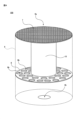
- FIG. FIG. 2 is a perspective view of a main portion of the plating apparatus 100.
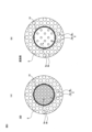
- Fig. 5(A) is a plan view of the flow rate control plate 8 and the cylindrical member 10 of the plating apparatus 100.
- Fig. 5(B) is a plan view of a flow rate control plate 8' which is a modified example of the flow rate control plate 8 of the plating apparatus 100, and the cylindrical member 10.
- Fig. 5(A) is a plan view of the flow rate control plate 8 and the cylindrical member 10 of the plating apparatus 100.
- Fig. 5(B) is a plan view of a flow rate control plate 8' which is a modified example of the
- FIG. 6(A) is a plan view showing a mesh member 7' which is a modified example of the mesh member 7 of the plating apparatus 100.
- Fig. 6(B) is a plan view showing a mesh member 7" which is a modified example of the mesh member 7 of the plating apparatus 100.
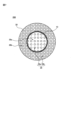
- FIG. 11 is a plan view of a main portion of a plating apparatus 200 according to a second embodiment.
- each embodiment is an illustrative example of how the present invention can be implemented, and the present invention is not limited to the contents of the embodiment. It is also possible to combine the contents described in different embodiments, and the implementation in such cases is also included in the present invention.
- the drawings are intended to aid in understanding the specification, and may be drawn diagrammatically, and the dimensional ratios of the depicted components or between the components may not match the dimensional ratios of those components described in the specification. Components described in the specification may be omitted in the drawings, or the number of components may be omitted when drawn.
- FIG. 1 is a cross-sectional view of the plating apparatus 100.
- FIG. 2 is also a cross-sectional view of the plating apparatus 100, showing the A-A portion indicated by the dashed-dotted arrow in FIG. 1.
- FIG. 3 is a cross-sectional view of the main part of the plating apparatus 100.
- FIG. 4 is a perspective view of the main part of the plating apparatus 100, showing the injection unit 6.
- FIG. 5(A) is a plan view of the flow rate control plate 8 and the cylindrical member 10 of the plating apparatus 100.
- FIG. 5(B) is a plan view of the flow rate control plate 8', which is a modified example of the flow rate control plate 8, and the cylindrical member 10.
- the plating apparatus 100 is equipped with a plating tank 1.
- the plating tank 1 is open at the top.
- the plating tank 1 is used to store a mixture 19 of plating solution, objects to be plated, media, and insulating balls, which will be described later. However, the insulating balls can be omitted if not necessary.
- the plating apparatus 100 includes a cylindrical metal tube 2 inside a plating tank 1.
- the metal tube 2 has a hollow portion 2a.
- the metal tube 2 is a first electrode, and in this embodiment, it is a cathode electrode.
- the metal tube 2 is cylindrical.
- the metal tube 2 may also be polygonal cylindrical.
- the material of the metal tube 2 is arbitrary, and various metals can be used.
- the dimensions of the metal tube 2, such as the outer diameter, inner diameter, and length, are arbitrary and can be set as appropriate.
- two rod-shaped conductive support parts 2b are formed integrally with the metal tube 2 at the top of the metal tube 2.
- the number of support parts 2b is arbitrary and is not limited to two.
- the plating apparatus 100 includes a partition tube 3 made of an insulating material inside the plating tank 1.
- the partition tube 3 has a hollow portion 3a.
- the partition tube 3 is cylindrical.
- the partition tube 3 may be a polygonal tube.
- the partition tube 3 has a plurality of small holes 3b formed therein that allow the plating solution to pass through but not the object to be plated, the media, and the insulating balls. When a current is applied between the metal tube 2, which is the first electrode, and the second electrode 5, the holes 3b pass the current through the plating solution.
- the partition tube 3 may be made of any material, and may be made of, for example, various resins.
- the dimensions of the partition tube 3, such as the outer diameter, inner diameter, and length, may be any dimension and may be set as appropriate.
- the inner diameter of the partition tube 3 is larger than the outer diameter of the metal tube 2.
- the metal tube 2 is disposed within the hollow portion 3a of the partition tube 3.
- a plating formation portion 4 is formed between the inside of the partition tube 3 and the outside of the metal tube 2.
- the plating formation portion 4 is the area (space) where plating is applied to the object to be plated. Note that in Figures 1, 2, and 3, the plating formation portion 4 is depicted as a cross-hatched portion.
- the plating formation portion 4 is the area between the outer diameter of the metal tube 2 and the inner diameter of the partition tube 3.
- the length and other dimensions of the plating formation portion 4 are arbitrary and can be set as appropriate.
- the object to be plated, the media, and the insulating balls are accumulated inside the plating forming section 4 and gradually descend downward. During this descent, plating is applied to the surface of the object to be plated.
- the plating apparatus 100 is equipped with a second electrode 5 inside the plating tank 1.
- the second electrode 5 is an anode electrode.
- the second electrode 5 is made of a cylindrical metal.
- the second electrode 5 is disposed on the outside of the partition tube 3.
- the material of the second electrode 5 is arbitrary, and various metals can be used.
- the plating apparatus 100 when viewed in a planar direction, the plating apparatus 100 has the metal tube 2, the partition tube 3, and the second electrode 5 arranged concentrically so that their central axes coincide. Therefore, in the plating apparatus 100, a current is applied uniformly between the metal tube 2 (the first electrode) and the second electrode 5 in any region of the plating formation section 4, suppressing variation in the thickness of the plating film that is formed.
- the plating device 100 is provided with an injection unit 6 below the metal tube 2.
- the injection unit 6 is for generating an upward flow of plating solution inside the metal tube 2.
- the injection unit 6 is an inner tube having a bottom surface that extends horizontally, an inner wall that extends in the height direction from the bottom surface, and an opening formed at the upper end of the inner wall.
- the inner tube shape of the injection unit 6 is an inner cylinder shape.
- the inner tube shape of the injection unit 6 is not limited to an inner cylinder shape and may be other shapes.
- the dimensions of the inner diameter, depth, etc. of the injection unit 6 are arbitrary and can be set appropriately.
- the inner diameter dimension of the injection unit 6 is preferably the same as the inner diameter dimension of the metal tube 2, but there is no problem if they are different.
- the first injection nozzle 6a is formed in an opening formed at the upper end of the injection part 6.
- the shape and dimensions of the first injection nozzle 6a are arbitrary, but in this embodiment it is circular with a diameter of 28 mm.
- a second injection nozzle 6b is formed on the bottom surface of the injection part 6. Plating solution is injected from the second injection nozzle 6b into the injection part 6. Plating solution is injected from the first injection nozzle 6a into the plating tank 1.
- the opening area of the second injection nozzle 6b is smaller than the opening area of the first injection nozzle 6a.
- the diameter of the second injection port 6b is smaller than the inner diameter of the metal tube 2. This also causes the plating solution to flow faster in the center of the metal tube 2, so measures to suppress the plating solution flow in the center of the metal tube 2 are required.
- a mesh member 7 is provided at the first injection port 6a of the injection unit 6.
- the mesh member 7 is provided to prevent the plated object, media, insulating balls, etc. from falling into the injection unit 6 when the injection of the injection unit 6 is stopped.
- the mesh member 7 is also circular when viewed in a planar direction.
- the mesh member 7 is entirely made of a single layer of mesh with a mesh size of 900 ⁇ m.
- the mesh member may be made of a central mesh portion 7a and a peripheral mesh portion 7b provided on the outside of the central mesh portion 7a, with the central mesh portion 7a made of multiple layers (for example, two layers) of mesh and the peripheral mesh portion 7b made of a single layer of mesh.
- the shape and dimensions of the central mesh portion 7a are the same as those of the central portion 8a of the flow rate control plate 8 described later and the shape and dimensions of the inner diameter of the cylindrical member 10 described later, but there is no problem if they are different.
- the central mesh portion 7a of the mesh member 7' is circular, while the central mesh portion 7a of the mesh member 7" is rectangular.
- the "opening" of a mesh is the distance between adjacent lines in a mesh in which vertical and horizontal lines intersect (not including wire diameter).
- the opening is sometimes called the opening (OP) or opening dimension.
- OP opening
- the opening generally refers to the opening of one layer of mesh, but in the present application documents, when multiple meshes are stacked, it may refer to the overall opening of the multiple meshes.
- the mesh openings in the central mesh portion 7a are smaller than those in the peripheral mesh portion 7b. Therefore, in the mesh members 7' and 7", the speed of the plating solution passing through the central mesh portion 7a is slower than the speed of the plating solution passing through the peripheral mesh portion 7b.
- the mesh that constitutes the mesh members 7, 7', and 7" may be made of any material, but nylon, for example, may be used.
- the meshes may be joined, for example, with an adhesive, or may be overlapped and the ends fixed.
- the plating device 100 is provided with a flow rate control plate 8 halfway up the height of the injection unit 6, parallel to the bottom surface of the injection unit 6.
- the flow rate control plate 8 has a central portion 8a and a peripheral portion 8b provided outside the central portion 8a when viewed in a planar direction.
- the shape and dimensions of the flow rate control plate 8 are arbitrary, but in this embodiment it is a disk shape with a diameter of 28 mm.
- the shape and dimensions of the central portion 8a are also arbitrary, but in this embodiment it is a circle with a diameter of 20 mm.
- the material of the flow rate control plate 8 is arbitrary, but for example, polyvinyl chloride can be used.
- the flow rate control plate 8 has a number of holes 9 (9a, 9b) formed through both main surfaces.
- the shape of the holes 9 (9a, 9b) is arbitrary, but in this embodiment, they are circular when viewed in the planar direction. If the holes 9 (9a, 9b) are circular, they can be easily formed by irradiating them with laser light or by drilling them with a drill.
- the opening area of each of the holes 9a formed in the central portion 8a is smaller than the opening area of each of the holes 9b formed in the peripheral portion 8b.
- the diameter of each of the holes 9a formed in the central portion 8a is 1.2 mm
- the diameter of each of the holes 9b formed in the peripheral portion 8b is 3.0 mm.
- the pattern shape of the central portion 8a where the holes 9a are formed and the pattern shape of the peripheral portion 8b where the holes 9b are formed are similar. More specifically, multiple holes 9a with a diameter of 1.2 mm are formed in the central portion 8a in a matrix shape (checkerboard shape) with a predetermined interval. Then, while maintaining the shape, the hole diameter, including the hole spacing, is enlarged until it reaches a diameter of 3.0 mm, and holes 9b are formed in the peripheral portion 8b using the enlarged hole spacing and the enlarged hole diameter. Therefore, in this embodiment, the total opening area of the multiple holes 9a per unit area in the central portion 8a is equal to the total opening area of the multiple holes 9b per unit area in the peripheral portion 8b.
- the total opening area of the holes 9a per unit area does not necessarily have to be equal to the total opening area of the holes 9b per unit area in the peripheral portion 8b.
- the total opening area of the holes 9a per unit area in the central portion 8a is smaller than the total opening area of the holes 9b per unit area in the peripheral portion 8b.
- the opening area of each of the holes 9a formed in the central portion 8a is smaller than the opening area of each of the holes 9b formed in the peripheral portion 8b, so the resistance to the plating solution passing through the central portion 8a is greater than the resistance to the plating solution passing through the peripheral portion 8b. Therefore, the speed of the plating solution passing through the central portion 8a is suppressed.
- the smaller the opening area of the hole the greater the resistance to the fluid, and the larger the opening area of the hole, the smaller the resistance to the fluid.
- the speed of the plating solution passing through the central portion 8a can be suppressed compared to the speed of the plating solution passing through the peripheral portion 8b.
- the total opening area of the holes 9a per unit area in the central portion 8a is equal to the total opening area of the holes 9b per unit area in the peripheral portion 8b.
- the total opening area of the holes 9a per unit area in the central portion 8a may be smaller than the total opening area of the holes 9b per unit area in the peripheral portion 8b.
- the distance between the centers of the holes 9a formed in the central portion 8a is the same as the distance between the centers of the holes 9b formed in the peripheral portion 8b, and the diameter of the holes 9a is 1.2 mm and the diameter of the holes 9b is 3.0 mm.
- the total opening area of the multiple holes 9a per unit area in the central portion 8a be the same as or smaller than the total opening area of the multiple holes 9b per unit area in the peripheral portion 8b. Even if the total opening area of the multiple holes 9a per unit area in the central portion 8a is larger than the total opening area of the multiple holes 9b per unit area in the peripheral portion 8b, as long as the opening area of each of the holes 9a formed in the central portion 8a is sufficiently smaller than the opening area of each of the holes 9b formed in the peripheral portion 8b, the speed of the plating solution passing through the central portion 8a can be suppressed compared to the speed of the plating solution passing through the peripheral portion 8b.
- the plating device 100 has a hollow cylindrical member 10 between the flow rate control plate 8 and the mesh member 7 of the first injection port 6a.
- the shape and dimensions of the cylindrical member 10 are arbitrary, but it is preferable that they are the same as the shape and dimensions of the central portion 8a of the flow rate control plate 8. However, there is no problem if they are different.
- the cylindrical member 10 is cylindrical with an inner diameter of 20 mm.
- FIG. 5(A) when the flow rate control plate 8 and the cylindrical member 10 are viewed in a planar direction, the central portion 8a of the flow rate control plate 8 is located inside the cylindrical member 10, and the peripheral portion 8b of the flow rate control plate 8 is located outside the cylindrical member 10.
- the cylindrical member 10 is provided to maintain the difference between the speed of the plating solution passing through the central portion 8a (slow) and the speed of the plating solution passing through the peripheral portion 8b (fast), which is generated by the flow rate control plate 8, up to the first injection port 6a of the injection unit 6 where the mesh member 7 is provided.
- the lower end of the tubular member 10 is preferably in contact with the flow rate control plate 8. However, there is no problem if a gap is left between the lower end of the tubular member 10 and the flow rate control plate 8. Also, it is preferable that the upper end of the tubular member 10 is in contact with the mesh member 7. However, there is no problem if a gap is left between the upper end of the tubular member 10 and the mesh member 7.
- the plating apparatus 100 is equipped with a circulation line 11 formed of a pipe. One end of the circulation line 11 is connected to a suction port 12 formed in the plating tank 1. The other end of the circulation line 11 is connected to a second injection port 6b of the injection unit 6. A pump 13 and a filter 14 are provided midway along the circulation line 11. When the pump 13 is driven, the circulation line 11 sucks up plating solution through the suction port 12 and injects the plating solution from the second injection port 6b.
- the plating apparatus 100 is provided with a mixing section 15 below the metal tube 2 and the partition tube 3 and above the injection section 6.
- the mixing section 15 is an area where the plating solution injected from the first injection port 6a of the injection section 6 is mixed with the plated object, media, and insulating balls that have descended through the plating formation section 4.
- the mixing section 15 is made of an insulating material, and has an inverted truncated cone-shaped excavation formed on the upper surface. Note that an inverted truncated cone is a truncated cone whose upper base is larger than its lower base.
- the shape of the excavation is arbitrary, and it may be a mortar shape instead of an inverted truncated cone shape.
- the first nozzle 6a of the injection unit 6 is disposed on the bottom surface of the mixing section 15. As described above, a mesh member 7 is provided at the first nozzle 6a of the injection unit 6. Because the mesh member 7 is provided at the first nozzle 6a, the object to be plated, media, insulating balls, etc. do not fall into the injection unit 6 even when the injection of the injection unit 6 is stopped.
- the plating device 100 is provided with an induction section 16 above the metal tube 2 and the partition tube 3.
- the induction section 16 is an area where the plated object, media, and insulating balls, which rise on the upward flow of plating solution formed inside the hollow section 2a of the metal tube 2 by the injection from the first injection port 6a of the injection section 6 and are ejected (discharged) from the upper opening of the hollow section 2a of the metal tube 2, are stirred and then guided to the plating formation section 4.
- the induction section 16 is made of an insulating material and has an inverted truncated cone shape in this embodiment.
- the upper end of the metal tube 2 protrudes from the bottom surface of the induction section 16.
- the upper end of the hollow section 2a of the metal tube 2 opens at the bottom surface of the induction section 16.
- the bottom surface of the induction section 16 is connected to the partition tube 3.
- the plating device 100 is equipped with an insulating reflector 17 above the opening of the plating tank 1.
- the reflector 17 is sometimes called a deflector.
- the reflector 17 plays a role in preventing the plating solution from scattering.
- the support part 2b of the metal tube 2 is attached to the underside of the reflector 17.
- a cylindrical suppression plate 17a is formed on the underside of the reflector 17.
- the suppression plate 17a is disposed within the induction section 16. The plating solution may overflow from the upper edge of the induction section 16, but the suppression plate 17a ensures that only the plating solution overflows from the induction section 16, preventing the plated object, media, and insulating balls from overflowing.
- the plating apparatus 100 is equipped with a power supply 18.
- One line of the power supply 18 is connected to the support portion 2b of the metal tube 2, which is the first electrode, and the other line is connected to the second electrode 5.
- the power supply 18 applies a current between the metal tube 2, which is the first electrode, and the second electrode 5.
- the plating device 100 which has the above structure, is provided with a flow rate control plate 8 and a cylindrical member 10, so that the speed of the plating solution sprayed from the first nozzle 6a of the spray unit 6 is controlled (adjusted). Specifically, the speed of the plating solution that passes through the center 8a of the flow rate control plate 8, then passes inside the cylindrical member 10, and is sprayed from the first nozzle 6a of the spray unit 6 is suppressed (slowed down) compared to the speed of the plating solution that passes through the peripheral portion 8b of the flow rate control plate 8, then passes outside the cylindrical member 10, and is sprayed from the first nozzle 6a of the spray unit 6.
- the speed at which the plating solution rises inside the first electrode, the metal tube 2 is faster in the center of the metal tube 2 and slower in the peripheral areas closer to the inner wall of the metal tube 2. Furthermore, when the flow rate of the plating solution sprayed from the spray unit 6 is increased, it is believed that of the objects to be plated that are sprayed out from the upper end of the metal tube 2 and rise to a high position in the plating solution stored in the plating tank, these are primarily objects that rise all the way up through the center of the metal tube 2, where the plating solution moves at a faster rate.
- the speed at which the plating solution passes through the inside of the tubular member 10 and is sprayed from the first nozzle 6a of the spray unit 6 is slower than the speed at which the plating solution passes through the outside of the tubular member 10 and is sprayed from the first nozzle 6a of the spray unit 6, so the speed at which the plating solution rises in the center of the metal tube 2 is suppressed. More specifically, when the amount of plating solution sprayed from the spray unit 6 is constant, the plating apparatus 100 can reduce the speed at which the plating solution rises in the center of the metal tube 2 compared to when the flow rate control plate 8 and the tubular member 10 are not provided.
- the plating apparatus 100 increases the amount of plating solution sprayed from the spray unit 6, shortens the time it takes for the object to pass through the plating formation unit 4 once, and increases the number of times the object to be plated circulates through the plating apparatus, but the object to be plated does not rise too high in the stored plating solution. Therefore, the plating apparatus 100 prevents defects such as cracks, chips, and peeling of the plating film on the object to be plated caused by the object to rise to a high position in the stored plating solution.
- the object to be plated, media, and insulating balls are introduced into the induction section 16 in the plating tank 1.
- the order of introduction of the plating solution and the object to be plated, media, and insulating balls may be reversed.
- the introduced object to be plated, media, and insulating balls are deposited in the plating formation section 4.
- the pump 13 is driven to spray the plating solution from the first nozzle 6a of the spray section 6.
- an upward flow of plating solution is generated inside the metal tube 2.
- some of the objects to be plated, media, and insulating balls that had accumulated inside the plating formation section 4 are taken out from the lower end of the plating formation section 4 to the mixing section 15, where they mix with the sprayed plating solution and ride the upward flow upward inside the metal tube 2.
- the plated object, media, and insulating balls that rise inside the metal tube 2 are ejected from the top end of the metal tube 2 and agitated.
- stirred objects to be plated, media, and insulating balls are deposited on top of other objects to be plated, media, and insulating balls that are already deposited in the plating formation section 4.
- the newly accumulated plated objects, media, and insulating balls gradually descend as some of the plated objects, media, and insulating balls that had accumulated in the plating formation section 4 are removed from the lower end of the plating formation section 4 to the mixing section 15. As a result, the plated objects, media, and insulating balls circulate inside the plating device 100.
- the power supply 18 is driven to apply a current between the first electrode, the metal tube 2, and the second electrode 5. As a result, plating of the object to be plated begins in the plating formation section 4.
- the power source 18 is turned off, and plating on the object to be plated is stopped.
- the pump 13 is turned off, and the object to be plated, media, and insulating balls stop circulating inside the plating device 100.
- the plating process is completed by removing the objects to be plated, media, and insulating balls from plating tank 1 and sorting the objects to be plated.
- the plating apparatus 100 used in Example 1 and the plating apparatus 100 used in Example 2 differ in the diameter dimension of the central portion 8a of the flow rate control plate 8 and the inner diameter dimension of the tubular member 10. Furthermore, unlike the plating apparatus of the present invention used in Comparative Example 1, the plating apparatus does not include the flow rate control plate 8 and the tubular member 10, unlike the plating apparatus 100.
- the plating apparatus 100 of Example 1, the plating apparatus 100 of Example 2, and the plating apparatus of Comparative Example 1 have the same configuration except for the flow rate control plate 8 and the cylindrical member 10.
- the length of the plating formation section 4 is 220 mm in each case.
- Example 1 was carried out.
- the flow rate control plate 8 was made circular with a diameter of 28 mm, and the central portion 8a of the flow rate control plate 8 was made circular with a diameter of 15 mm.
- the tubular member 10 was made cylindrical with an inner diameter of 15 mm.
- the plating apparatus 100 used in Example 1 formed multiple holes 9a with a diameter of 1.2 mm in the central portion 8a of the flow rate control plate 8, and multiple holes 9b with a diameter of 3.0 mm in the peripheral portion 8b of the flow rate control plate 8.
- the pattern shape of the central portion 8a where the holes 9a are formed and the pattern shape of the peripheral portion 8b where the holes 9b are formed are similar to each other.
- the pattern shape of the peripheral portion 8b where the holes 9b are formed is the pattern shape of the central portion 8a where the holes 9a are formed, enlarged until the diameter of the holes, including the spacing between the holes, is 3.0 mm.
- the plating solution was placed in the plating tank 1 of the plating device 100.
- the object to be plated, media, and insulating balls were placed in the induction section 16 in the plating tank 1 of the plating device 100.
- the total amount of the object to be plated, media, and insulating balls was 1720cc.
- the mixing ratio was 1376cc (80% by volume) of the object to be plated, 86cc (5% by volume) of media, and 258cc (15% by volume) of insulating balls.
- the pump 13 was driven at low power to inject the plating solution from the first injection port 6a of the injection section 6, and the plated object, media, and insulating balls were circulated in the order of the mixing section 15, the hollow section 2a of the metal tube 2, the induction section 16, the plating formation section 4, and the mixing section 15.
- the output of the pump 13 was gradually increased to increase the circulation speed of the plated object, media, and insulating balls. Then, when the plated object discharged from the upper end of the hollow section 2a of the metal tube 2 and the object that rose relatively high (erupted) in the stored plating solution reached a predetermined height, the output of the pump 13 was stopped from being increased and the output of the pump 13 was made constant.
- the power source 18 was driven to apply a current between the first electrode (metal tube 2) and the second electrode 5, and plating of the object to be plated was started in the plating formation section 4.
- Example 1 the amount of plating solution sprayed from the first nozzle 6a of the spray unit 6 was 39 L/min. Also, the time required for each plated object to pass through the plating formation unit 4 once was 10.5 seconds.
- Example 2 was carried out.
- the plating apparatus 100 used in Example 2 had a flow rate control plate 8 that was circular with a diameter of 28 mm, a central portion 8a of the flow rate control plate 8 that was circular with a diameter of 20 mm, and a tubular member 10 that was cylindrical with an inner diameter of 20 mm.
- Example 2 Furthermore, in the plating apparatus 100 used in Example 2, similar to Example 1, multiple holes 9a with a diameter of 1.2 mm were formed in the central portion 8a of the flow rate control plate 8, and multiple holes 9b with a diameter of 3.0 mm were formed in the peripheral portion 8b of the flow rate control plate 8. Note that the pattern shape of the central portion 8a where the holes 9a are formed and the pattern shape of the peripheral portion 8b where the holes 9b are formed are similar to each other, similar to Example 1.
- Example 2 plating solution was placed in the plating tank 1 of the plating device 100 under the same conditions as in Example 1.
- Example 2 the object to be plated, media, and insulating balls were placed in the induction section 16 in the plating tank 1 of the plating device 100 under the same conditions as in Example 1.
- Example 2 under the same conditions as in Example 1, the pump 13 was driven at low output, and then the output of the pump 13 was gradually increased until the object to be plated, which was discharged from the top end of the hollow portion 2a of the metal tube 2 and rose relatively high in the stored plating solution, reached half the height between the top end of the metal tube 2 and the liquid level of the plating solution contained in the plating tank 1, at which point the output of the pump 13 was made constant.
- the power source 18 was driven to apply a current between the first electrode, the metal tube 2, and the second electrode 5, and plating of the object to be plated was started in the plating formation section 4.
- Example 2 the amount of plating solution sprayed from the first nozzle 6a of the spray unit 6 (flow rate of plating solution) was measured in this state. In addition, the time required for each plated object to pass through the plating formation unit 4 once was measured in this state.
- Example 2 the amount of plating solution sprayed from the first nozzle 6a of the spray unit 6 was 40 L/min. Also, the time required for each plated object to pass through the plating formation unit 4 once was 6.1 seconds.
- Comparative Example 1 was carried out. As described above, the plating apparatus used in Comparative Example 1 did not include the flow rate control plate 8 and the cylindrical member 10. The other configurations of the plating apparatus used in Comparative Example 1 were the same as those of the plating apparatus 100.
- Comparative Example 1 the object to be plated, media, and insulating balls were placed in the induction section 16 in the plating tank 1 of the plating device 100 under the same conditions as in Examples 1 and 2.
- Comparative Example 1 the amount of plating solution sprayed from the first nozzle 6a of the spray unit 6 was 34 L/min. Also, the time required for each plated object to pass through the plating formation unit 4 once was 16.7 seconds.
- Example 1 and Example 2 had a higher flow rate of the plating solution and a shorter time required for the object to be plated to pass through the plating formation section 4 once than Comparative Example 1.
- Example 2 in which the diameter of the central portion 8a of the flow rate control plate 8 and the inner diameter of the tubular member 10 are larger, has a higher flow rate of plating solution and a shorter time required for the plated object to pass through the plating formation section 4 once than Example 1, in which the diameter of the central portion 8a of the flow rate control plate 8 and the inner diameter of the tubular member 10 are smaller.
- the flow rate of plating solution can be increased and the time required for the plated object to pass through the plating formation section 4 once can be shortened by relatively increasing the diameter of the central portion 8a of the flow rate control plate 8 and the inner diameter of the tubular member 10, which suppress the speed of the plating solution.
- the present invention can reduce the variation in thickness of the plating film formed by increasing the flow rate of the plating solution and increasing the number of times the plated object circulates through the plating device while suppressing the occurrence of defects in the plated object.
- Fig. 7 shows a plating apparatus 200 according to the second embodiment.
- Fig. 7 is a plan view of a main part of the plating apparatus 200.
- Fig. 7 is a plan view of the flow rate control plate 28 and the cylindrical member 10 of the plating apparatus 200.
- the plating apparatus 200 according to the second embodiment is a modification of the plating apparatus 100 according to the first embodiment described above. The modifications are described below.
- the opening area of each of the holes 9a formed in the central portion 8a is smaller than the opening area of each of the holes 9b formed in the peripheral portion 8b.
- the opening area of each of the holes 29a formed in the central portion 28a is the same as the opening area of each of the holes 29b formed in the peripheral portion 28b.
- the number of holes 29a formed per unit area in the central portion 28a is smaller than the number of holes 29b formed per unit area in the peripheral portion 28b.
- the other configurations of the plating apparatus are the same as those of the plating apparatus 100.
- the total opening area per unit area of the multiple holes 29a formed in the central portion 28a is smaller than the total opening area per unit area of the multiple holes 29b formed in the peripheral portion 28b.
- the speed of the plating solution passing through the central portion 28a of the flow rate control plate 28, passing through the inside of the cylindrical member 10, and being sprayed from the first nozzle 6a of the spray unit 6 is suppressed (slowed down) compared to the speed of the plating solution passing through the peripheral portion 28b of the flow rate control plate 28, passing through the outside of the cylindrical member 10, and being sprayed from the first nozzle 6a of the spray unit 6.
- the plating apparatus 200 even if the amount of plating solution sprayed from the spray unit 6 is increased to reduce the time required for the plated object to pass through the plating formation unit 4 once, and the number of times the plated object circulates through the plating apparatus is increased, for the purpose of suppressing the variation in the thickness of the plating film, the plated object is less likely to be defective.
- the mesh member 7 is composed of a single layer of mesh throughout, but as shown in FIG. 6(A), the mesh member 7' may be composed of a central mesh portion 7a and a peripheral mesh portion 7b provided on the outside of the central mesh portion 7a, with the central mesh portion 7a composed of multiple layers of mesh and the peripheral mesh portion 7b composed of a single layer of mesh.
- the speed of the plating solution passing through the central mesh portion 7a in the mesh member 7' can also be reduced to be lower than the speed of the plating solution passing through the peripheral mesh portion 7b, further enhancing the effect of the present invention.
- the plating apparatus according to one embodiment of the present invention is as described in the "Means for solving the problems" section.
- the opening area of each of the holes formed in the central portion is smaller than the opening area of each of the holes formed in the peripheral portion.
- the resistance to the plating solution passing through each of the holes formed in the central portion is greater than the resistance to the plating solution passing through each of the holes formed in the peripheral portion, so the speed of the plating solution passing through the central portion can be suppressed compared to the speed of the plating solution passing through the peripheral portion.
- the total opening area per unit area of the multiple holes formed in the central portion is the same as or smaller than the total opening area per unit area of the multiple holes formed in the peripheral portion. In this case, the speed of the plating solution passing through the central portion can be further suppressed.
- each of the holes formed in the central portion is the same as that of each of the holes formed in the peripheral portion, but the number of holes formed in the central portion per unit area is smaller than the number of holes formed in the peripheral portion per unit area. In this case, the speed of the plating solution passing through the central portion can be suppressed compared to the speed of the plating solution passing through the peripheral portion.
- the total opening area per unit area of the multiple holes formed in the central portion is smaller than the total opening area per unit area of the multiple holes formed in the peripheral portion. In this case, the speed of the plating solution passing through the central portion can be suppressed compared to the speed of the plating solution passing through the peripheral portion.
- the center of the flow rate control plate is disposed inside the cylindrical member, and the peripheral portion of the flow rate control plate is disposed outside the cylindrical member.
- the difference in speed of the plating solution passing through the center portion and the plating solution passing through the peripheral portion, which is generated by the flow rate control plate can be maintained as is up to the first injection port of the injection unit.
- the holes formed in the center and the holes formed in the peripheral area are each circular. In this case, it becomes easier to form holes in the flow rate control plate.
- the mesh member When viewed in a planar direction, the mesh member has a central mesh portion and a peripheral mesh portion provided outside the central mesh portion, and it is also preferable that the mesh opening in the central mesh portion is smaller than the mesh opening in the peripheral mesh portion. In this case, the speed of the plating solution passing through the central mesh portion can also be reduced in the mesh member to be slower than the speed of the plating solution passing through the peripheral mesh portion. In this case, it is also preferable that the mesh member in the peripheral mesh portion is made of a single layer of mesh, and the mesh member in the central mesh portion is made of multiple layers of mesh.
- the speed at which the plating solution rises inside the metal tube can be controlled, and in particular, the flow of plating solution that rises quickly through the center of the inside of the metal tube can be suppressed (slowed down).
- the plating apparatus comprises a partition tube made of an insulating material, tubular with a hollow portion and having a plurality of holes formed therein that allow the plating solution to pass through but not the object to be plated, and a second electrode, the metal tube being the first electrode, the metal tube, the partition tube, and the second electrode being each contained in a plating tank, the metal tube being disposed within the hollow portion of the partition tube, a plating formation portion being formed between the inside of the partition tube and the outside of the metal tube, the second electrode being disposed on the outside of the partition tube, the spray portion being provided below the metal tube, the object to be plated being carried by the upward flow of plating solution sprayed by the spray portion, rising within the hollow portion of the metal tube, being discharged from the upper end of the hollow portion of the metal tube, being agitated within the plating solution, and then descending within the plating formation portion, and during the descent, a current is applied between the metal tube, which is the first electrode, and the second electrode,
- the first electrode is, for example, a cathode electrode
- the second electrode is, for example, an anode electrode.
- Plating tank 2 Metal tube (first electrode; cathode) 2a: hollow portion 2b: support portion 3: partition tube 3a: hollow portion 3b: hole 4: plating forming portion 5: second electrode (anode) 6: Injection section 6a: first injection port 6b: second injection port 7, 7', 7": mesh member 7a: mesh central portion 7b: mesh peripheral portion 8, 28: flow rate control plate 8a, 28a: central portion 8b, 28b: peripheral portion 9, 29: holes 9a, 29a: holes (formed in central portion 8a) 9b, 29b...holes (formed in the peripheral portion 8b) 10: Cylindrical member 11: Circulation line 12: Suction port 13: Pump 14: Filter 15: Mixing section 16: Guiding section 17: Reflector (deflector) 17a: Suppression plate 18: Power source
Landscapes
- Chemical & Material Sciences (AREA)
- Engineering & Computer Science (AREA)
- Chemical Kinetics & Catalysis (AREA)
- Electrochemistry (AREA)
- Materials Engineering (AREA)
- Metallurgy (AREA)
- Organic Chemistry (AREA)
- Electroplating Methods And Accessories (AREA)
Abstract
Description
(a)各被めっき物に、予め定めた厚さ以上の厚さのめっき膜が形成されること。
(b)同時にめっきされた複数の被めっき物の間において、形成されためっき膜の厚さのばらつきが小さいこと(予め定めた許容値内であること)。
図1、図2、図3、図4(A)、(B)に、第1実施形態にかかるめっき装置100を示す。ただし、図1はめっき装置100の断面図である。図2もめっき装置100の断面図であり、図1の一点鎖線矢印で示したA-A部分を示している。図3は、めっき装置100の要部断面図である。図4は、めっき装置100の要部斜視図であり、噴射部6を示している。図5(A)は、めっき装置100の流速制御板8と筒状部材10の平面図である。図5(B)は、流速制御板8の変形例である流速制御板8’と、筒状部材10の平面図である。
以下に、めっき装置100を使用した、めっき工程の一例を示す。
本願発明の有効性を確認するために、以下の実験を実施した。具体的には、上述しためっき装置100を使用して実施例1、実施例2を実施し、本発明のめっき装置以外のめっき装置を使用して比較例1を実施した。なお、本実験においては、流速制御板8の中央部8aの直径の寸法や、筒状部材10の内径の寸法などが異なっていても、流速制御板8と筒状部材10とを備えていれば、そのめっき装置は、めっき装置100に属するものとする。

図7に、第2実施形態にかかるめっき装置200を示す。ただし、図7は、めっき装置200の要部平面図である。具体的には、図7は、めっき装置200の流速制御板28と筒状部材10との平面図である。
2・・・金属管(第1電極;カソード)
2a・・・中空部
2b・・・支持部
3・・・隔壁管
3a・・・中空部
3b・・・孔
4・・・めっき形成部
5・・・第2電極(アノード)
6・・・噴射部
6a・・・第1噴射口
6b・・・第2噴射口
7、7’、7”・・・メッシュ部材
7a・・・メッシュ中央部
7b・・・メッシュ周辺部
8、28・・・流速制御板
8a、28a・・・中央部
8b、28b・・・周辺部
9、29・・・孔
9a、29a・・・孔(中央部8aに形成されたもの)
9b、29b・・・孔(周辺部8bに形成されたもの)
10・・・筒状部材
11・・・循環ライン
12・・・吸液口
13・・・ポンプ
14・・・フィルタ
15・・・混合部
16・・・誘導部
17・・・反射板(デフレクタ)
17a・・・抑制板
18・・・電源
Claims (12)
- 被めっき物が含まれためっき液を貯留するめっき槽と、
前記めっき槽に形成された、前記めっき液を噴射する噴射部と、を備え、
前記噴射部から噴射された前記めっき液によって、前記めっき液に含まれた前記被めっき物が攪拌される、めっき装置であって、
前記噴射部は、水平方向に拡がる底面と、前記底面から高さ方向に伸びる内壁と、前記内壁の上端に形成された開口とを有する内筒状であり、
前記開口は、前記めっき槽に前記めっき液を噴射する第1噴射口であり、
前記第1噴射口にメッシュ部材が設けられ、
前記底面に、前記噴射部に前記めっき液を噴射する第2噴射口が設けられ、
前記噴射部の前記高さ方向の途中に、前記底面と平行に、複数の孔が形成された流速制御板が設けられ、
前記流速制御板は、平面方向に見たとき、中央部と、前記中央部の外側に設けられた周辺部と、を有し、
前記中央部および前記周辺部に、それぞれ、複数の前記孔が形成され、
前記流速制御板と、前記第1噴射口の前記メッシュ部材との間に、中空部を有する筒状部材が設けられた、
めっき装置。 - 前記中央部に形成された前記孔の各開口面積が、前記周辺部に形成された前記孔の各開口面積よりも小さい、
請求項1に記載されためっき装置。 - 前記中央部に形成された複数の前記孔の単位面積当たりの総開口面積が、前記周辺部に形成された複数の前記孔の単位面積当たりの総開口面積と同じか、または、小さい、
請求項2に記載されためっき装置。 - 前記中央部に形成された前記孔の各開口面積と前記周辺部に形成された前記孔の各開口面積とは同じであるが、前記中央部に形成された前記孔の単位面積あたりの数が、前記周辺部に形成された前記孔の単位面積あたりの数よりも少ない、
請求項1に記載されためっき装置。 - 前記中央部に形成された複数の前記孔の単位面積当たりの総開口面積が、前記周辺部に形成された複数の前記孔の単位面積当たりの総開口面積よりも小さい、
請求項1に記載されためっき装置。 - 前記流速制御板と前記筒状部材とを、平面方向に見たとき、
前記筒状部材の内側に、前記流速制御板の前記中央部が配置され、
前記筒状部材の外側に、前記流速制御板の前記周辺部が配置された、
請求項1ないし5のいずれか1項に記載されためっき装置。 - 前記流速制御板を、平面方向に見たとき、
前記中央部に形成された前記孔、および、前記周辺部に形成された前記孔が、それぞれ、円形である、
請求項1ないし6のいずれか1項に記載されためっき装置。 - 前記メッシュ部材は、平面方向に見たとき、メッシュ中央部と、前記メッシュ中央部の外側に設けられたメッシュ周辺部と、を有し、
前記メッシュ中央部の目開きが、前記メッシュ周辺部の目開きよりも、小さい、
請求項1ないし7のいずれか1項に記載されためっき装置。 - 前記メッシュ周辺部の前記メッシュ部材が1層のメッシュからなり、
前記メッシュ中央部の前記メッシュ部材が複数層のメッシュからなる、
請求項8に記載されためっき装置。 - 前記噴射部の直上に、中空部を有する筒状の金属管が設けられた、
請求項1ないし9のいずれか1項に記載されためっき装置。 - 絶縁性の材質で作製され、中空部を有する筒状で、前記めっき液は通過させるが前記被めっき物は通過させない複数の孔が形成された隔壁管と、
第2電極と、を備え、
前記金属管は、第1電極であり、
前記金属管と、前記隔壁管と、前記第2電極とは、それぞれ、前記めっき槽に収容され、
前記隔壁管の前記中空部内に、前記金属管が配置され、前記隔壁管の内側と前記金属管の外側との間に、めっき形成部が形成され、
前記隔壁管の外側に、前記第2電極が配置され、
前記噴射部は、前記金属管の下方に設けられ、
前記被めっき物は、
前記噴射部が噴射させた前記めっき液の上昇流に乗って、前記金属管の前記中空部の中を上昇し、
前記金属管の前記中空部の上端から外に排出されて、前記めっき液の中で攪拌された後に、
前記めっき形成部の中を降下し、
前記降下中に、前記第1電極である前記金属管と、前記第2電極との間に、電流が印加されることによって、めっきされる、
請求項10に記載されためっき装置。 - 前記第1電極が、カソード電極であり、
前記第2電極が、アノード電極である、
請求項11に記載されためっき装置。
Priority Applications (3)
| Application Number | Priority Date | Filing Date | Title |
|---|---|---|---|
| CN202380063735.6A CN119744317A (zh) | 2022-09-27 | 2023-08-05 | 镀敷装置 |
| JP2024549817A JPWO2024070236A1 (ja) | 2022-09-27 | 2023-08-05 | |
| US18/985,144 US20250116029A1 (en) | 2022-09-27 | 2024-12-18 | Plating apparatus |
Applications Claiming Priority (2)
| Application Number | Priority Date | Filing Date | Title |
|---|---|---|---|
| JP2022154280 | 2022-09-27 | ||
| JP2022-154280 | 2022-09-27 |
Related Child Applications (1)
| Application Number | Title | Priority Date | Filing Date |
|---|---|---|---|
| US18/985,144 Continuation US20250116029A1 (en) | 2022-09-27 | 2024-12-18 | Plating apparatus |
Publications (1)
| Publication Number | Publication Date |
|---|---|
| WO2024070236A1 true WO2024070236A1 (ja) | 2024-04-04 |
Family
ID=90477147
Family Applications (1)
| Application Number | Title | Priority Date | Filing Date |
|---|---|---|---|
| PCT/JP2023/028661 Ceased WO2024070236A1 (ja) | 2022-09-27 | 2023-08-05 | めっき装置 |
Country Status (4)
| Country | Link |
|---|---|
| US (1) | US20250116029A1 (ja) |
| JP (1) | JPWO2024070236A1 (ja) |
| CN (1) | CN119744317A (ja) |
| WO (1) | WO2024070236A1 (ja) |
Citations (1)
| Publication number | Priority date | Publication date | Assignee | Title |
|---|---|---|---|---|
| WO2017217216A1 (ja) * | 2016-06-16 | 2017-12-21 | 株式会社村田製作所 | めっき装置およびめっき方法 |
-
2023
- 2023-08-05 CN CN202380063735.6A patent/CN119744317A/zh active Pending
- 2023-08-05 JP JP2024549817A patent/JPWO2024070236A1/ja active Pending
- 2023-08-05 WO PCT/JP2023/028661 patent/WO2024070236A1/ja not_active Ceased
-
2024
- 2024-12-18 US US18/985,144 patent/US20250116029A1/en active Pending
Patent Citations (1)
| Publication number | Priority date | Publication date | Assignee | Title |
|---|---|---|---|---|
| WO2017217216A1 (ja) * | 2016-06-16 | 2017-12-21 | 株式会社村田製作所 | めっき装置およびめっき方法 |
Also Published As
| Publication number | Publication date |
|---|---|
| US20250116029A1 (en) | 2025-04-10 |
| CN119744317A (zh) | 2025-04-01 |
| JPWO2024070236A1 (ja) | 2024-04-04 |
Similar Documents
| Publication | Publication Date | Title |
|---|---|---|
| US10711365B2 (en) | Plating apparatus and plating method | |
| US8329006B2 (en) | Electroplating cell with hydrodynamics facilitating more uniform deposition across a workpiece during plating | |
| KR101880599B1 (ko) | 애노드 이동형 수평도금장치 | |
| JP5762137B2 (ja) | めっき方法 | |
| US20080035475A1 (en) | Electroplating cell with hydrodynamics facilitating more uniform deposition on a workpiece with through holes during plating | |
| JP6793761B2 (ja) | 表面処理装置およびその方法 | |
| CN1452235A (zh) | 涂层形成方法、涂层形成设备、装置、装置制造方法及电子设备 | |
| WO2024070234A1 (ja) | めっき装置 | |
| JP3150370U (ja) | 電解めっき装置 | |
| US20250116029A1 (en) | Plating apparatus | |
| JP7848882B2 (ja) | めっき装置 | |
| KR102242585B1 (ko) | 셀렉티브 솔더볼 저감 노즐장치 | |
| TW200405490A (en) | Method for arraying tiny particles through liquid, tiny particles arraying device, and semiconductor device | |
| JP6568398B2 (ja) | 洗浄装置及び洗浄方法 | |
| JP2012125903A (ja) | 放電加工装置 | |
| JP7111068B2 (ja) | めっき装置およびめっき方法 | |
| JP7156325B2 (ja) | めっき方法 | |
| JP2011080135A (ja) | ワークの内面処理方法とワークの内面処理装置 | |
| JP2014070265A (ja) | バレルめっき装置およびこのバレルめっき装置を用いた電子部品の製造方法 | |
| US20230032943A1 (en) | Substrate treating apparatus and substrate treating method | |
| JP2013159854A (ja) | 亜鉛溶解装置、めっき装置 | |
| JP7178870B2 (ja) | めっき処理装置 | |
| JP4811609B2 (ja) | バレル装置ならびにバレルめっき方法 | |
| JPH10317199A (ja) | めっき方法およびめっき装置 | |
| JPH07308512A (ja) | 消泡装置 |
Legal Events
| Date | Code | Title | Description |
|---|---|---|---|
| 121 | Ep: the epo has been informed by wipo that ep was designated in this application |
Ref document number: 23871478 Country of ref document: EP Kind code of ref document: A1 |
|
| WWE | Wipo information: entry into national phase |
Ref document number: 2024549817 Country of ref document: JP |
|
| WWE | Wipo information: entry into national phase |
Ref document number: 202380063735.6 Country of ref document: CN |
|
| WWP | Wipo information: published in national office |
Ref document number: 202380063735.6 Country of ref document: CN |
|
| NENP | Non-entry into the national phase |
Ref country code: DE |
|
| 122 | Ep: pct application non-entry in european phase |
Ref document number: 23871478 Country of ref document: EP Kind code of ref document: A1 |