WO2024069813A1 - ギア構造 - Google Patents
ギア構造 Download PDFInfo
- Publication number
- WO2024069813A1 WO2024069813A1 PCT/JP2022/036271 JP2022036271W WO2024069813A1 WO 2024069813 A1 WO2024069813 A1 WO 2024069813A1 JP 2022036271 W JP2022036271 W JP 2022036271W WO 2024069813 A1 WO2024069813 A1 WO 2024069813A1
- Authority
- WO
- WIPO (PCT)
- Prior art keywords
- web
- web portion
- gear
- gear structure
- outer peripheral
- Prior art date
- Legal status (The legal status is an assumption and is not a legal conclusion. Google has not performed a legal analysis and makes no representation as to the accuracy of the status listed.)
- Ceased
Links
Images





Classifications
-
- F—MECHANICAL ENGINEERING; LIGHTING; HEATING; WEAPONS; BLASTING
- F16—ENGINEERING ELEMENTS AND UNITS; GENERAL MEASURES FOR PRODUCING AND MAINTAINING EFFECTIVE FUNCTIONING OF MACHINES OR INSTALLATIONS; THERMAL INSULATION IN GENERAL
- F16H—GEARING
- F16H48/00—Differential gearings
- F16H48/38—Constructional details
- F16H48/40—Constructional details characterised by features of the rotating cases
-
- F—MECHANICAL ENGINEERING; LIGHTING; HEATING; WEAPONS; BLASTING
- F16—ENGINEERING ELEMENTS AND UNITS; GENERAL MEASURES FOR PRODUCING AND MAINTAINING EFFECTIVE FUNCTIONING OF MACHINES OR INSTALLATIONS; THERMAL INSULATION IN GENERAL
- F16H—GEARING
- F16H55/00—Elements with teeth or friction surfaces for conveying motion; Worms, pulleys or sheaves for gearing mechanisms
- F16H55/02—Toothed members; Worms
- F16H55/17—Toothed wheels
Definitions
- the present invention relates to a gear structure used in various power transmission mechanisms, and in particular to a gear mechanism suitable for use in vehicles.
- Patent Document 1 discloses that a cavity is provided in a ring gear that constitutes a vehicle differential device to reduce weight while maintaining strength and rigidity, that an oil passage is provided from the cavity to the outer periphery of the ring gear, and that these structures are manufactured using a three-dimensional additive manufacturing device.
- the entire structure is molded as a single unit using a 3D additive manufacturing device, which makes it difficult to allocate the appropriate material to the gear teeth, which require strength.
- the molded parts are large, the manufacturing time is long, resulting in poor productivity.
- the present invention was made in consideration of the above-mentioned conventional situation, and aims to provide a gear structure that has a split structure, can ensure the necessary strength in the teeth, and can shorten manufacturing time and improve productivity.
- the gear structure of the present invention comprises a shaft portion which is a rotating shaft, an annular web portion which is fixed to the outer periphery of the shaft portion, and an annular tooth portion which has a predetermined number of teeth which mesh with other gears and is fixed to the outer periphery of the web portion.
- the web portion comprises a hollow portion formed along the circumferential direction, a protrusion portion formed along the circumferential direction at one end in the width direction of the outer periphery, a groove portion formed along the circumferential direction at the other end in the width direction of the outer periphery, a wheel stopper which fits into the groove, and an annular wheel stopper cover which fits into the outer periphery and covers the wheel stopper, and is characterized in that the tooth portion is restrained in the width direction on the outer periphery of the web portion by the protrusion portion and the wheel stopper which fits into the groove.
- the gear structure of the present invention is basically divided into three parts: a shaft portion, a web portion, and a teeth portion.
- the web portion has a cavity, which contributes to weight reduction.
- This web portion can be formed using a sintered material or by a three-dimensional additive manufacturing method.
- the teeth portion can be allocated a material selected to ensure the strength required for the teeth.
- the gear structure fixes the web portion to the shaft, and fixes the teeth portion to the web portion, and at that time, the teeth portion is restrained against the web portion by a wheel stopper and a wheel stopper cover.
- the gear structure can be made into a split structure, ensuring the necessary strength in the teeth, thereby shortening manufacturing time and improving productivity.
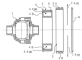
- FIG. 2 is a cross-sectional view showing each member in an exploded state in the first embodiment of the gear structure.
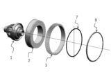
- FIG. 2 is an exploded perspective view showing the gear structure.
- FIG. 4 is a cross-sectional view showing a gear structure.
- FIG. 1 is a side view of a gear structure.
- FIG. 4 is a front view of the gear structure as viewed from the axial direction of the rotating shaft.
- 4A and 4B are front and side views of the web portion.
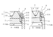
- 7 is a cross-sectional view taken along lines AA and BB in FIG. 6.
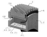
- 4 is an enlarged perspective view showing a main part of the wheel fastening cover.
- FIG. 1 is a front view showing the wheel fastening side surface of the wheel fastening cover.
- FIG. 1 is a front view showing the wheel fastening side surface of the wheel fastening cover.
- FIG. 10 is a cross-sectional view taken along lines AA and BB in FIG. 9.
- FIG. 4 is an explanatory diagram showing the flow of gear oil from a web portion to a wheel stopper.
- FIG. 4 is a perspective view illustrating the flow of gear oil from a web portion to a tooth row portion.
- FIG. 11 is a perspective view of a power transmission device showing a second embodiment of a gear structure.
- FIG. 14 is a cross-sectional view of the gear structure shown in FIG.
- the gear structure shown in Figures 1 to 5 basically comprises a shaft portion 1 which is a rotating shaft, an annular web portion 2 fixed to the outer periphery of the shaft portion 1, and an annular toothed portion 3 which has a predetermined number of teeth 3A which mesh with another gear (not shown) and is fixed to the outer periphery of the web portion 2.
- the shaft portion 1 is a differential case that constitutes a differential device of a vehicle, although it is not particularly limited thereto. Therefore, the illustrated gear structure meshes a pinion provided on the output shaft of a motor (not shown) with the tooth row portion 3, and transmits the rotation of the motor to the axle after reducing the speed via the differential case.
- the manufacturing method of the shaft portion 1 is not particularly limited, but for example, a material is formed into a predetermined shape by cutting, and then heat-treated or finished as necessary.
- the web portion 2 has a hollow portion 4 formed along the circumferential direction, a protrusion portion 5 formed along the circumferential direction at one end in the width direction of the outer peripheral surface (the left end side in Figures 6 and 7), and a groove portion 6 formed along the circumferential direction at the other end in the width direction of the outer peripheral surface.
- the web portion 2 also has a wheel stopper 7 that fits into the groove portion 6, and an annular wheel stopper cover 8 that fits into the outer peripheral surface and covers the wheel stopper 7.
- the wheel stopper 7 and the wheel stopper cover 8 are separate parts from the web portion 2.
- the web portion 2 has a hollow portion 4, a ridge portion 5, and a groove portion 6 around the entire circumference.
- the hollow portion 4 of the web portion 2 is divided into a plurality of partition walls 2A (12 in the illustrated example) arranged at predetermined intervals in the circumferential direction, as shown on the left side of Figure 7.
- Each divided space 4A of the web portion 2 has an oil filler port 4B that is open in the width direction of the web portion 2, and an oil flow path 4C that communicates from the inside to the outer periphery of the web portion 2.
- Each oil filler port 4B is formed on one side of the web portion 2 (the left side in the right drawing in Figure 7).
- Each oil flow path 4C is also formed on the outer periphery wall of the web portion 2, next to the groove portion 6.
- the method of manufacturing the web portion 2 having such a structure is not particularly limited, but for example, a sintered material is used to form a green compact of a predetermined shape by pressing, and after going through the steps of assembling and sintering the green compact, finishing is performed as necessary.
- the web portion 2 can also be formed by a three-dimensional additive manufacturing method.
- the ring stopper 7 is made of, for example, metal, and as shown in FIG. 1, is divided into two semicircular members 7A, 7A.
- the two semicircular members 7A, 7A are fitted into the groove 6 of the web portion 2 to receive the thrust load of the toothed section 3.
- the wheel retaining cover 8 is made of, for example, metal, and as shown in Figures 8 to 10, has a relatively small diameter inner circumferential groove portion 8A and a relatively large diameter outer circumferential groove portion 8B concentrically arranged on one side (the side facing the wheel retaining 7).
- the inner circumferential groove portion 8A is formed in a position that opens toward the wheel retaining 7 when the wheel retaining 7 and the wheel retaining cover 8 are fixed to the web portion 2.
- the outer circumferential groove portion 8B is formed in a position that opens toward the tooth portion 3 in the same fixed state.
- the wheel retaining cover 8 has communication passages 8C at positions corresponding to each divided space 4 of the web portion 2, i.e., at multiple positions spaced at the same intervals as each divided space 4, which connect the oil passages 4C, the inner peripheral groove portion 8A, and the outer peripheral groove portion 8B of the web portion 2 to each other.
- the toothed portion 3 is made of metal, and a certain number of teeth 3A are integrally formed on the outer peripheral surface of the annular body 3B.
- the manufacturing method of this toothed portion 3 is not particularly limited, but for example, it is made by cutting teeth on an annular material, and then subjecting it to heat treatment or finishing as necessary.
- the inner circumference of the web portion 2 is fitted onto the outer circumference of the shaft portion 1. In this case, it is also effective to form unevenness in advance on the joint surfaces of the shaft portion 1 and the web portion 2, spline-connect the two, and restrict their circumferential movement.
- the inner circumference of the web portion 2 may be press-fitted into the outer circumference of the shaft portion 1 to connect the two to each other.
- the inner periphery of the annular body 3B of the toothed section 3 is fitted onto the outer periphery of the web section 2. In this case, it is also effective to form unevenness in advance on the joint surfaces of the web section 2 and the toothed section 3, spline-couple them, and restrict their circumferential movement. Also, in the gear structure, the inner periphery of the annular body 3B of the toothed section 3 may be press-fitted into the outer periphery of the web section 2 to connect the two to each other.
- the gear structure When the toothed section 3 is fitted to the web section 2 as described above, the gear structure abuts one widthwise end of the toothed section 3 against the protrusion 5 on the outer peripheral surface of the web section 2. The gear structure then attaches a wheel retainer 7 to a groove 6 on the outer peripheral surface of the web section 2, and then presses and fixes a wheel retainer cover 8 to the outer peripheral portion of the web section 2. As a result, the gear structure restrains both widthwise ends of the toothed section 3 on the outer peripheral surface of the web section 2 by the protrusion 5 and the wheel retainer 6.
- the above gear structure is basically divided into three parts: shaft portion 1, web portion 2, and tooth row portion 3.
- Web portion 2 has a hollow portion 4, which contributes to weight reduction and improved heat dissipation.
- Tooth row portion 3 can be made of a material selected to ensure the strength required for the teeth 3A. As a result, because the gear structure is a divided structure, the necessary strength is ensured for the teeth, shortening manufacturing time and improving productivity.
- a high-strength material such as iron can be used for the shaft portion 1 as in the past.
- the web portion 2 can be formed using a sintered material or a three-dimensional laminated material.
- a sintered material is used to manufacture the web portion 2
- a complex structure having a partition wall 2A, a cavity 4, a dividing space 4A, an oil supply port 4B, and an oil flow path 4C can be obtained by simply assembling and sintering a press-molded green compact.
- the resonant frequency of the web portion 2 can be designed, and a highly damped structure can be obtained because the sintered material is a highly damped material.
- the above gear structure can firmly connect the shaft portion 1 and the web portion 2, and the web portion 2 and the tooth portion 3, without using separate parts such as bolts, by spline-connecting at least one of the combinations of the shaft portion 1 and the web portion 2 and the tooth portion 3, thereby contributing to improved assembly workability and further weight reduction.
- the hollow portion 4 of the web portion 2 is divided into a plurality of divided spaces 4 by a plurality of partition walls 2A arranged in the circumferential direction, and each divided space 4A has an oil supply port 4B that opens in the width direction of the web portion 2 and an oil flow path 4C that communicates from the inside to the outer periphery of the web portion 2.
- the radially arranged partition walls 2A function as reinforcing ribs, so that the overall mechanical strength of the web portion 2 of the gear structure can be further increased.
- the above gear structure can store gear oil in a gear case (not shown). At this time, the gear oil is in an amount that allows the oil filler port 4B to be submerged below the web portion 2, as shown by the oil level S of the oil reservoir in FIG. 3.
- the gear structure can employ a structure in which an oil pump P is disposed in the gear case, and gear oil is sprayed toward the oil filler port 4B disposed on the circumference of the web portion 2, as shown by the arrow in FIG. 3.
- the gear structure may also be such that as the gear rotates, the teeth 3A of the toothed section 3 scoop up gear oil from the oil pool and pour the gear oil into an oil catcher located near the top of the toothed section 3A.
- the gear oil may be circulated from the oil catcher to appropriate areas requiring lubrication and then returned to the oil pool.
- gear oil is supplied from each oil supply port 4B into each divided space 4A.
- the gear oil in the divided space 4A moves to the outer periphery of the divided space 4A due to centrifugal force generated by the rotation, and is supplied to the tooth row section 3 side through the oil flow path 4C.
- the gear structure can smoothly circulate gear oil through the web section 2 within the gear case, thereby realizing lubrication and cooling of the gear mechanism.
- the wheel retaining cover 8 shown in Figures 8 and 9 has, on one side thereof, an inner peripheral groove portion 8A that opens toward the wheel retaining portion 7 and an outer peripheral groove portion 8B that opens toward the tooth row portion 3, arranged in a concentric manner, and also has a communication flow path 8C at a position corresponding to each divided space 4A of the web portion 2, which connects the oil flow path 4C with the inner peripheral groove portion 8A and the outer peripheral groove portion 8B.
- the gear structure described above allows the gear oil flowing out of the oil flow passages 4C of each divided space 4A to flow from the communicating passages 8C into the inner peripheral groove portion 8A and the outer peripheral groove portion 8B, and is smoothly supplied to the circumferential direction of the tooth row portion 3 and to the teeth 3A, thereby further improving the lubrication and cooling functions of the gear mechanism.
- the gear oil flows from the divided space 4A between the wheel retaining 7 and the wheel retaining cover 8, that is, through the communicating passages 8C, due to centrifugal force, and then flows in the circumferential direction of the wheel retaining cover 8 as shown in Figure 11 and is supplied to the tooth row portion 3.
- Second Embodiment 13 includes an output gear 52 provided on an output shaft 51 of a motor (not shown), an intermediate gear 53 meshing with the output gear 52, and a final gear 54 meshing with the intermediate gear 53.
- the gear structure of this embodiment is an example applied to the intermediate gear 53, which has a higher rotation speed than the final gear 54.
- the gear structure comprises a shaft portion 11 which is a rotating shaft, an annular web portion 12 which is fixed to the outer periphery of the shaft portion 1, and an annular tooth row portion 13 which has a predetermined number of teeth 13A which mesh with other gears and is fixed to the outer periphery of the web portion 12.
- the gear structure also comprises a wheel stopper, a wheel stopper cover, etc., similar to the first embodiment.
- the shaft portion 11 has a gear oil flow path 11A on its axis.
- the web portion 12 has a cavity 14 along the circumferential direction, an oil supply port 14B that connects the flow path 11A of the shaft portion 11 to the cavity 14, and an oil flow path 14C that connects the cavity 14 to the tooth row portion 13.
- the gear structure having the above configuration is basically composed of a shaft portion 11, a web portion 12, and a toothed portion 3, and during rotation, gear oil supplied to the flow path 11A of the shaft portion 11 is introduced into the hollow portion 14A from the oil supply port 14B, and is further supplied to the toothed portion 13 through the oil flow path 14C. At this time, the gear structure uses the centrifugal force generated during rotation to supply gear oil to the web portion 12 and the toothed portion 13. Even with this gear structure, it is possible to obtain the same action and effect as in the first embodiment.
- the gear structure according to the present invention is not limited to the configuration of the above-mentioned embodiments, but can be modified as appropriate without departing from the spirit of the present invention.
- the gear structure can be applied to various gear mechanisms such as rotation transmission devices that use a motor or engine as an output source.
Landscapes
- Engineering & Computer Science (AREA)
- General Engineering & Computer Science (AREA)
- Mechanical Engineering (AREA)
- Gears, Cams (AREA)
Priority Applications (2)
| Application Number | Priority Date | Filing Date | Title |
|---|---|---|---|
| JP2024548928A JP7755818B2 (ja) | 2022-09-28 | 2022-09-28 | ギア構造 |
| PCT/JP2022/036271 WO2024069813A1 (ja) | 2022-09-28 | 2022-09-28 | ギア構造 |
Applications Claiming Priority (1)
| Application Number | Priority Date | Filing Date | Title |
|---|---|---|---|
| PCT/JP2022/036271 WO2024069813A1 (ja) | 2022-09-28 | 2022-09-28 | ギア構造 |
Publications (1)
| Publication Number | Publication Date |
|---|---|
| WO2024069813A1 true WO2024069813A1 (ja) | 2024-04-04 |
Family
ID=90476833
Family Applications (1)
| Application Number | Title | Priority Date | Filing Date |
|---|---|---|---|
| PCT/JP2022/036271 Ceased WO2024069813A1 (ja) | 2022-09-28 | 2022-09-28 | ギア構造 |
Country Status (2)
| Country | Link |
|---|---|
| JP (1) | JP7755818B2 (https=) |
| WO (1) | WO2024069813A1 (https=) |
Citations (4)
| Publication number | Priority date | Publication date | Assignee | Title |
|---|---|---|---|---|
| JPH01126457U (https=) * | 1988-02-22 | 1989-08-29 | ||
| JPH0735736U (ja) * | 1993-11-18 | 1995-07-04 | ダイハツ工業株式会社 | 内燃機関におけるアイドル歯車用支持軸の取付け装置 |
| JP3155760U (ja) * | 2009-08-26 | 2009-12-03 | 王 昇輝 | 回転機構 |
| JP2017116064A (ja) * | 2015-12-25 | 2017-06-29 | マツダ株式会社 | ディファレンシャル装置及びその製造方法 |
-
2022
- 2022-09-28 WO PCT/JP2022/036271 patent/WO2024069813A1/ja not_active Ceased
- 2022-09-28 JP JP2024548928A patent/JP7755818B2/ja active Active
Patent Citations (4)
| Publication number | Priority date | Publication date | Assignee | Title |
|---|---|---|---|---|
| JPH01126457U (https=) * | 1988-02-22 | 1989-08-29 | ||
| JPH0735736U (ja) * | 1993-11-18 | 1995-07-04 | ダイハツ工業株式会社 | 内燃機関におけるアイドル歯車用支持軸の取付け装置 |
| JP3155760U (ja) * | 2009-08-26 | 2009-12-03 | 王 昇輝 | 回転機構 |
| JP2017116064A (ja) * | 2015-12-25 | 2017-06-29 | マツダ株式会社 | ディファレンシャル装置及びその製造方法 |
Also Published As
| Publication number | Publication date |
|---|---|
| JP7755818B2 (ja) | 2025-10-17 |
| JPWO2024069813A1 (https=) | 2024-04-04 |
Similar Documents
| Publication | Publication Date | Title |
|---|---|---|
| EP3135958B1 (en) | Power transmission apparatus | |
| US9797495B2 (en) | Clutch and differential device with same | |
| US6279221B1 (en) | Vehicle driveshaft | |
| JP6288050B2 (ja) | 構造体のケース及びその製造方法 | |
| JP4179349B2 (ja) | リングギヤ、内燃機関始動回転力伝達機構及びリングギヤ製造方法 | |
| JP3978647B2 (ja) | 車輪軸受 | |
| JP2017075627A (ja) | スプライン継手 | |
| US12370886B2 (en) | Electric drive device for a motor vehicle | |
| JP7755818B2 (ja) | ギア構造 | |
| JP6176266B2 (ja) | プラネタリギヤ装置 | |
| JP5727745B2 (ja) | ギヤ支持構造 | |
| EP1473489B1 (en) | Differential gearing for vehicle including planetary gear mechanism and method of manufacturing same | |
| JP6341216B2 (ja) | 車両の動力伝達装置 | |
| JP2009518592A (ja) | ダブルクラッチ式変速機の変速機軸の軸受構造 | |
| CN104565105A (zh) | 板载具、多板离合器和制造板载具的工艺 | |
| DE102012106331A1 (de) | Anlasser | |
| JP6742715B2 (ja) | 差動装置 | |
| JP2006166491A (ja) | インナーロータ型回転電機 | |
| JP6306728B2 (ja) | デファレンシャル装置 | |
| CN112638685B (zh) | 用于车辆的驱动轮的轮毂装置 | |
| JP2008095724A (ja) | フェースギア及びこれを用いたデファレンシャル装置 | |
| JP6365449B2 (ja) | 自動変速機及びその製造方法 | |
| WO2019172255A1 (ja) | 車両駆動装置 | |
| JP7226145B2 (ja) | 自動変速機及び摩擦締結装置構成要素の製造方法 | |
| JP7303637B2 (ja) | インホイールモータ駆動装置 |
Legal Events
| Date | Code | Title | Description |
|---|---|---|---|
| 121 | Ep: the epo has been informed by wipo that ep was designated in this application |
Ref document number: 22960876 Country of ref document: EP Kind code of ref document: A1 |
|
| WWE | Wipo information: entry into national phase |
Ref document number: 2024548928 Country of ref document: JP |
|
| NENP | Non-entry into the national phase |
Ref country code: DE |
|
| 122 | Ep: pct application non-entry in european phase |
Ref document number: 22960876 Country of ref document: EP Kind code of ref document: A1 |