WO2024069813A1 - Gear structure - Google Patents
Gear structure Download PDFInfo
- Publication number
- WO2024069813A1 WO2024069813A1 PCT/JP2022/036271 JP2022036271W WO2024069813A1 WO 2024069813 A1 WO2024069813 A1 WO 2024069813A1 JP 2022036271 W JP2022036271 W JP 2022036271W WO 2024069813 A1 WO2024069813 A1 WO 2024069813A1
- Authority
- WO
- WIPO (PCT)
- Prior art keywords
- web
- web portion
- gear
- gear structure
- outer peripheral
- Prior art date
Links
- 230000002093 peripheral effect Effects 0.000 claims abstract description 27
- 238000005192 partition Methods 0.000 claims description 7
- 238000004519 manufacturing process Methods 0.000 abstract description 13
- 239000003921 oil Substances 0.000 description 29
- 239000012208 gear oil Substances 0.000 description 18
- 239000000463 material Substances 0.000 description 12
- 230000007246 mechanism Effects 0.000 description 6
- 239000000654 additive Substances 0.000 description 4
- 230000000996 additive effect Effects 0.000 description 4
- 239000000945 filler Substances 0.000 description 4
- 230000005540 biological transmission Effects 0.000 description 3
- 238000005461 lubrication Methods 0.000 description 3
- 239000002184 metal Substances 0.000 description 3
- 229910052751 metal Inorganic materials 0.000 description 3
- 239000013585 weight reducing agent Substances 0.000 description 3
- XEEYBQQBJWHFJM-UHFFFAOYSA-N Iron Chemical compound [Fe] XEEYBQQBJWHFJM-UHFFFAOYSA-N 0.000 description 2
- 238000001816 cooling Methods 0.000 description 2
- 238000004904 shortening Methods 0.000 description 2
- 238000005245 sintering Methods 0.000 description 2
- 238000005520 cutting process Methods 0.000 description 1
- 238000010586 diagram Methods 0.000 description 1
- 230000000694 effects Effects 0.000 description 1
- 230000017525 heat dissipation Effects 0.000 description 1
- 238000010438 heat treatment Methods 0.000 description 1
- 229910052742 iron Inorganic materials 0.000 description 1
- 239000002648 laminated material Substances 0.000 description 1
- 238000003825 pressing Methods 0.000 description 1
- 230000003014 reinforcing effect Effects 0.000 description 1
- 239000007787 solid Substances 0.000 description 1
- 230000036346 tooth eruption Effects 0.000 description 1
Images


Definitions
- the present invention relates to a gear structure used in various power transmission mechanisms, and in particular to a gear mechanism suitable for use in vehicles.
- Patent Document 1 discloses that a cavity is provided in a ring gear that constitutes a vehicle differential device to reduce weight while maintaining strength and rigidity, that an oil passage is provided from the cavity to the outer periphery of the ring gear, and that these structures are manufactured using a three-dimensional additive manufacturing device.
- the entire structure is molded as a single unit using a 3D additive manufacturing device, which makes it difficult to allocate the appropriate material to the gear teeth, which require strength.
- the molded parts are large, the manufacturing time is long, resulting in poor productivity.
- the present invention was made in consideration of the above-mentioned conventional situation, and aims to provide a gear structure that has a split structure, can ensure the necessary strength in the teeth, and can shorten manufacturing time and improve productivity.
- the gear structure of the present invention comprises a shaft portion which is a rotating shaft, an annular web portion which is fixed to the outer periphery of the shaft portion, and an annular tooth portion which has a predetermined number of teeth which mesh with other gears and is fixed to the outer periphery of the web portion.
- the web portion comprises a hollow portion formed along the circumferential direction, a protrusion portion formed along the circumferential direction at one end in the width direction of the outer periphery, a groove portion formed along the circumferential direction at the other end in the width direction of the outer periphery, a wheel stopper which fits into the groove, and an annular wheel stopper cover which fits into the outer periphery and covers the wheel stopper, and is characterized in that the tooth portion is restrained in the width direction on the outer periphery of the web portion by the protrusion portion and the wheel stopper which fits into the groove.
- the gear structure of the present invention is basically divided into three parts: a shaft portion, a web portion, and a teeth portion.
- the web portion has a cavity, which contributes to weight reduction.
- This web portion can be formed using a sintered material or by a three-dimensional additive manufacturing method.
- the teeth portion can be allocated a material selected to ensure the strength required for the teeth.
- the gear structure fixes the web portion to the shaft, and fixes the teeth portion to the web portion, and at that time, the teeth portion is restrained against the web portion by a wheel stopper and a wheel stopper cover.
- the gear structure can be made into a split structure, ensuring the necessary strength in the teeth, thereby shortening manufacturing time and improving productivity.
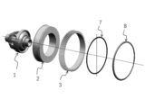
- FIG. 2 is a cross-sectional view showing each member in an exploded state in the first embodiment of the gear structure.
- FIG. 2 is an exploded perspective view showing the gear structure.
- FIG. 4 is a cross-sectional view showing a gear structure.
- FIG. 1 is a side view of a gear structure.
- FIG. 4 is a front view of the gear structure as viewed from the axial direction of the rotating shaft.
- 4A and 4B are front and side views of the web portion.
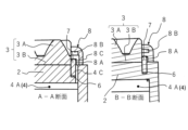
- 7 is a cross-sectional view taken along lines AA and BB in FIG. 6.
- 4 is an enlarged perspective view showing a main part of the wheel fastening cover.
- FIG. 1 is a front view showing the wheel fastening side surface of the wheel fastening cover.
- FIG. 1 is a front view showing the wheel fastening side surface of the wheel fastening cover.
- FIG. 10 is a cross-sectional view taken along lines AA and BB in FIG. 9.
- FIG. 4 is an explanatory diagram showing the flow of gear oil from a web portion to a wheel stopper.
- FIG. 4 is a perspective view illustrating the flow of gear oil from a web portion to a tooth row portion.
- FIG. 11 is a perspective view of a power transmission device showing a second embodiment of a gear structure.
- FIG. 14 is a cross-sectional view of the gear structure shown in FIG.
- the gear structure shown in Figures 1 to 5 basically comprises a shaft portion 1 which is a rotating shaft, an annular web portion 2 fixed to the outer periphery of the shaft portion 1, and an annular toothed portion 3 which has a predetermined number of teeth 3A which mesh with another gear (not shown) and is fixed to the outer periphery of the web portion 2.
- the shaft portion 1 is a differential case that constitutes a differential device of a vehicle, although it is not particularly limited thereto. Therefore, the illustrated gear structure meshes a pinion provided on the output shaft of a motor (not shown) with the tooth row portion 3, and transmits the rotation of the motor to the axle after reducing the speed via the differential case.
- the manufacturing method of the shaft portion 1 is not particularly limited, but for example, a material is formed into a predetermined shape by cutting, and then heat-treated or finished as necessary.
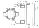
- the web portion 2 has a hollow portion 4 formed along the circumferential direction, a protrusion portion 5 formed along the circumferential direction at one end in the width direction of the outer peripheral surface (the left end side in Figures 6 and 7), and a groove portion 6 formed along the circumferential direction at the other end in the width direction of the outer peripheral surface.
- the web portion 2 also has a wheel stopper 7 that fits into the groove portion 6, and an annular wheel stopper cover 8 that fits into the outer peripheral surface and covers the wheel stopper 7.
- the wheel stopper 7 and the wheel stopper cover 8 are separate parts from the web portion 2.
- the web portion 2 has a hollow portion 4, a ridge portion 5, and a groove portion 6 around the entire circumference.
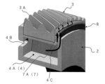
- the hollow portion 4 of the web portion 2 is divided into a plurality of partition walls 2A (12 in the illustrated example) arranged at predetermined intervals in the circumferential direction, as shown on the left side of Figure 7.
- Each divided space 4A of the web portion 2 has an oil filler port 4B that is open in the width direction of the web portion 2, and an oil flow path 4C that communicates from the inside to the outer periphery of the web portion 2.
- Each oil filler port 4B is formed on one side of the web portion 2 (the left side in the right drawing in Figure 7).
- Each oil flow path 4C is also formed on the outer periphery wall of the web portion 2, next to the groove portion 6.
- the method of manufacturing the web portion 2 having such a structure is not particularly limited, but for example, a sintered material is used to form a green compact of a predetermined shape by pressing, and after going through the steps of assembling and sintering the green compact, finishing is performed as necessary.
- the web portion 2 can also be formed by a three-dimensional additive manufacturing method.
- the ring stopper 7 is made of, for example, metal, and as shown in FIG. 1, is divided into two semicircular members 7A, 7A.
- the two semicircular members 7A, 7A are fitted into the groove 6 of the web portion 2 to receive the thrust load of the toothed section 3.
- the wheel retaining cover 8 is made of, for example, metal, and as shown in Figures 8 to 10, has a relatively small diameter inner circumferential groove portion 8A and a relatively large diameter outer circumferential groove portion 8B concentrically arranged on one side (the side facing the wheel retaining 7).
- the inner circumferential groove portion 8A is formed in a position that opens toward the wheel retaining 7 when the wheel retaining 7 and the wheel retaining cover 8 are fixed to the web portion 2.
- the outer circumferential groove portion 8B is formed in a position that opens toward the tooth portion 3 in the same fixed state.
- the wheel retaining cover 8 has communication passages 8C at positions corresponding to each divided space 4 of the web portion 2, i.e., at multiple positions spaced at the same intervals as each divided space 4, which connect the oil passages 4C, the inner peripheral groove portion 8A, and the outer peripheral groove portion 8B of the web portion 2 to each other.
- the toothed portion 3 is made of metal, and a certain number of teeth 3A are integrally formed on the outer peripheral surface of the annular body 3B.
- the manufacturing method of this toothed portion 3 is not particularly limited, but for example, it is made by cutting teeth on an annular material, and then subjecting it to heat treatment or finishing as necessary.
- the inner circumference of the web portion 2 is fitted onto the outer circumference of the shaft portion 1. In this case, it is also effective to form unevenness in advance on the joint surfaces of the shaft portion 1 and the web portion 2, spline-connect the two, and restrict their circumferential movement.
- the inner circumference of the web portion 2 may be press-fitted into the outer circumference of the shaft portion 1 to connect the two to each other.
- the inner periphery of the annular body 3B of the toothed section 3 is fitted onto the outer periphery of the web section 2. In this case, it is also effective to form unevenness in advance on the joint surfaces of the web section 2 and the toothed section 3, spline-couple them, and restrict their circumferential movement. Also, in the gear structure, the inner periphery of the annular body 3B of the toothed section 3 may be press-fitted into the outer periphery of the web section 2 to connect the two to each other.
- the gear structure When the toothed section 3 is fitted to the web section 2 as described above, the gear structure abuts one widthwise end of the toothed section 3 against the protrusion 5 on the outer peripheral surface of the web section 2. The gear structure then attaches a wheel retainer 7 to a groove 6 on the outer peripheral surface of the web section 2, and then presses and fixes a wheel retainer cover 8 to the outer peripheral portion of the web section 2. As a result, the gear structure restrains both widthwise ends of the toothed section 3 on the outer peripheral surface of the web section 2 by the protrusion 5 and the wheel retainer 6.
- the above gear structure is basically divided into three parts: shaft portion 1, web portion 2, and tooth row portion 3.
- Web portion 2 has a hollow portion 4, which contributes to weight reduction and improved heat dissipation.
- Tooth row portion 3 can be made of a material selected to ensure the strength required for the teeth 3A. As a result, because the gear structure is a divided structure, the necessary strength is ensured for the teeth, shortening manufacturing time and improving productivity.
- a high-strength material such as iron can be used for the shaft portion 1 as in the past.
- the web portion 2 can be formed using a sintered material or a three-dimensional laminated material.
- a sintered material is used to manufacture the web portion 2
- a complex structure having a partition wall 2A, a cavity 4, a dividing space 4A, an oil supply port 4B, and an oil flow path 4C can be obtained by simply assembling and sintering a press-molded green compact.
- the resonant frequency of the web portion 2 can be designed, and a highly damped structure can be obtained because the sintered material is a highly damped material.
- the above gear structure can firmly connect the shaft portion 1 and the web portion 2, and the web portion 2 and the tooth portion 3, without using separate parts such as bolts, by spline-connecting at least one of the combinations of the shaft portion 1 and the web portion 2 and the tooth portion 3, thereby contributing to improved assembly workability and further weight reduction.
- the hollow portion 4 of the web portion 2 is divided into a plurality of divided spaces 4 by a plurality of partition walls 2A arranged in the circumferential direction, and each divided space 4A has an oil supply port 4B that opens in the width direction of the web portion 2 and an oil flow path 4C that communicates from the inside to the outer periphery of the web portion 2.
- the radially arranged partition walls 2A function as reinforcing ribs, so that the overall mechanical strength of the web portion 2 of the gear structure can be further increased.
- the above gear structure can store gear oil in a gear case (not shown). At this time, the gear oil is in an amount that allows the oil filler port 4B to be submerged below the web portion 2, as shown by the oil level S of the oil reservoir in FIG. 3.
- the gear structure can employ a structure in which an oil pump P is disposed in the gear case, and gear oil is sprayed toward the oil filler port 4B disposed on the circumference of the web portion 2, as shown by the arrow in FIG. 3.
- the gear structure may also be such that as the gear rotates, the teeth 3A of the toothed section 3 scoop up gear oil from the oil pool and pour the gear oil into an oil catcher located near the top of the toothed section 3A.
- the gear oil may be circulated from the oil catcher to appropriate areas requiring lubrication and then returned to the oil pool.
- gear oil is supplied from each oil supply port 4B into each divided space 4A.
- the gear oil in the divided space 4A moves to the outer periphery of the divided space 4A due to centrifugal force generated by the rotation, and is supplied to the tooth row section 3 side through the oil flow path 4C.
- the gear structure can smoothly circulate gear oil through the web section 2 within the gear case, thereby realizing lubrication and cooling of the gear mechanism.
- the wheel retaining cover 8 shown in Figures 8 and 9 has, on one side thereof, an inner peripheral groove portion 8A that opens toward the wheel retaining portion 7 and an outer peripheral groove portion 8B that opens toward the tooth row portion 3, arranged in a concentric manner, and also has a communication flow path 8C at a position corresponding to each divided space 4A of the web portion 2, which connects the oil flow path 4C with the inner peripheral groove portion 8A and the outer peripheral groove portion 8B.
- the gear structure described above allows the gear oil flowing out of the oil flow passages 4C of each divided space 4A to flow from the communicating passages 8C into the inner peripheral groove portion 8A and the outer peripheral groove portion 8B, and is smoothly supplied to the circumferential direction of the tooth row portion 3 and to the teeth 3A, thereby further improving the lubrication and cooling functions of the gear mechanism.
- the gear oil flows from the divided space 4A between the wheel retaining 7 and the wheel retaining cover 8, that is, through the communicating passages 8C, due to centrifugal force, and then flows in the circumferential direction of the wheel retaining cover 8 as shown in Figure 11 and is supplied to the tooth row portion 3.
- Second Embodiment 13 includes an output gear 52 provided on an output shaft 51 of a motor (not shown), an intermediate gear 53 meshing with the output gear 52, and a final gear 54 meshing with the intermediate gear 53.
- the gear structure of this embodiment is an example applied to the intermediate gear 53, which has a higher rotation speed than the final gear 54.
- the gear structure comprises a shaft portion 11 which is a rotating shaft, an annular web portion 12 which is fixed to the outer periphery of the shaft portion 1, and an annular tooth row portion 13 which has a predetermined number of teeth 13A which mesh with other gears and is fixed to the outer periphery of the web portion 12.
- the gear structure also comprises a wheel stopper, a wheel stopper cover, etc., similar to the first embodiment.
- the shaft portion 11 has a gear oil flow path 11A on its axis.
- the web portion 12 has a cavity 14 along the circumferential direction, an oil supply port 14B that connects the flow path 11A of the shaft portion 11 to the cavity 14, and an oil flow path 14C that connects the cavity 14 to the tooth row portion 13.
- the gear structure having the above configuration is basically composed of a shaft portion 11, a web portion 12, and a toothed portion 3, and during rotation, gear oil supplied to the flow path 11A of the shaft portion 11 is introduced into the hollow portion 14A from the oil supply port 14B, and is further supplied to the toothed portion 13 through the oil flow path 14C. At this time, the gear structure uses the centrifugal force generated during rotation to supply gear oil to the web portion 12 and the toothed portion 13. Even with this gear structure, it is possible to obtain the same action and effect as in the first embodiment.
- the gear structure according to the present invention is not limited to the configuration of the above-mentioned embodiments, but can be modified as appropriate without departing from the spirit of the present invention.
- the gear structure can be applied to various gear mechanisms such as rotation transmission devices that use a motor or engine as an output source.
Abstract
Provided is a gear structure comprising a shaft portion 1, a web portion 2 which is fixed to an outer periphery of the shaft portion 1, and a toothing portion 3 which is fixed to an outer periphery of the web portion 2, wherein the web portion 2 includes a hollow portion 4 which is formed along the circumferential direction, a projection portion 5 which is formed on an outer peripheral surface, a groove portion 6, a wheel retainer 7, and a wheel retainer cover 8, and the toothing portion 3 is restrained in the width direction on the outer peripheral surface of the web portion 2 by the projection portion 5 and the wheel retainer 7 fitted to the groove portion 6. This gear structure has a split structure and can secure the strength required for teeth 3A and achieve a decrease in manufacturing time and an increase in productivity.
Description
本発明は、各種の動力伝達機構に用いられるギア構造に関し、とくに、車両に用いるのに好適なギア機構に関するものである。
The present invention relates to a gear structure used in various power transmission mechanisms, and in particular to a gear mechanism suitable for use in vehicles.
従来のギア機構としては、例えば、特許文献1に記載されているものがある。特許文献1には、車両のデファレンシャル装置を構成するリングギアに空洞を設けることで、強度剛性を確保した状態で軽量化を図ること、空洞からリングギアの外周部に油路を設けること、これらの構造を三次元積層造形装置を用いて作製することが開示されている。
An example of a conventional gear mechanism is described in Patent Document 1. Patent Document 1 discloses that a cavity is provided in a ring gear that constitutes a vehicle differential device to reduce weight while maintaining strength and rigidity, that an oil passage is provided from the cavity to the outer periphery of the ring gear, and that these structures are manufactured using a three-dimensional additive manufacturing device.
しかしながら、上記したような従来のギア構造では、三次元積層造形装置を用いて全体を一体成形することから、強度が必要な歯車の歯の部分に適切な材料を割り当てることが困難であり、また、成型部品として大型のものであるから、造形時間が長くかかり、生産性が悪いという問題点があった。
However, with the conventional gear structure described above, the entire structure is molded as a single unit using a 3D additive manufacturing device, which makes it difficult to allocate the appropriate material to the gear teeth, which require strength. In addition, because the molded parts are large, the manufacturing time is long, resulting in poor productivity.
本発明は、上記従来の状況に鑑みて成されたものであって、分割構造にして、歯の部分に必要な強度を確保することができ、製造時間の短縮化や生産性の向上を実現することができるギア構造を提供することを目的としている。
The present invention was made in consideration of the above-mentioned conventional situation, and aims to provide a gear structure that has a split structure, can ensure the necessary strength in the teeth, and can shorten manufacturing time and improve productivity.
本発明に係わるギア構造は、回転軸であるシャフト部と、シャフト部の外周に固定される環状のウェブ部と、他の歯車に噛み合う所定数の歯を有し且つウェブ部の外周に固定される環状の歯列部とを備えている。ウェブ部は、円周方向に沿って形成した空洞部と、外周面の幅方向一端側で円周方向に沿って形成した突条部と、外周面の幅方向他端側で円周方向に沿って形成した溝部と、溝部に嵌合する輪留めと、外周面に嵌合して輪留めを覆う環状の輪留めカバーとを備え、歯列部が、ウェブ部の外周面において、突条部と溝部に嵌合した輪留めとにより幅方向に拘束してあることを特徴としている。
The gear structure of the present invention comprises a shaft portion which is a rotating shaft, an annular web portion which is fixed to the outer periphery of the shaft portion, and an annular tooth portion which has a predetermined number of teeth which mesh with other gears and is fixed to the outer periphery of the web portion. The web portion comprises a hollow portion formed along the circumferential direction, a protrusion portion formed along the circumferential direction at one end in the width direction of the outer periphery, a groove portion formed along the circumferential direction at the other end in the width direction of the outer periphery, a wheel stopper which fits into the groove, and an annular wheel stopper cover which fits into the outer periphery and covers the wheel stopper, and is characterized in that the tooth portion is restrained in the width direction on the outer periphery of the web portion by the protrusion portion and the wheel stopper which fits into the groove.
本発明に係わるギア構造は、基本的に、シャフト部とウェブ部と歯列部とに3分割されている。ウェブ部は、空洞を有するので軽量化に寄与する。このウェブ部は、焼結材を用いて成形したり、三次元積層造形方法により成形したりすることが可能である。また、歯列部は、歯の部分に要求される強度を確保し得るように選択した材料を割り当てることが可能である。そして、ギア構造は、シャフトにウェブ部を固定し、ウェブ部に歯列部を固定し、その際、輪留め及び輪留めカバーにより、ウェブ部に対して歯列部を拘束する。
The gear structure of the present invention is basically divided into three parts: a shaft portion, a web portion, and a teeth portion. The web portion has a cavity, which contributes to weight reduction. This web portion can be formed using a sintered material or by a three-dimensional additive manufacturing method. The teeth portion can be allocated a material selected to ensure the strength required for the teeth. The gear structure fixes the web portion to the shaft, and fixes the teeth portion to the web portion, and at that time, the teeth portion is restrained against the web portion by a wheel stopper and a wheel stopper cover.
このようにして、ギア構造は、上記構成を採用したことにより、分割構造にして歯の部分に必要な強度を確保することができ、製造時間の短縮化や生産性の向上を実現することができる。
In this way, by adopting the above configuration, the gear structure can be made into a split structure, ensuring the necessary strength in the teeth, thereby shortening manufacturing time and improving productivity.
<第1実施形態>
図1~図5に示すギア構造は、基本構成として、回転軸であるシャフト部1と、シャフト部1の外周に固定される環状のウェブ部2と、他の歯車(図示略)に噛み合う所定数の歯3Aを有し且つウェブ部2の外周に固定される環状の歯列部3とを備えている。 First Embodiment
The gear structure shown in Figures 1 to 5 basically comprises ashaft portion 1 which is a rotating shaft, an annular web portion 2 fixed to the outer periphery of the shaft portion 1, and an annular toothed portion 3 which has a predetermined number of teeth 3A which mesh with another gear (not shown) and is fixed to the outer periphery of the web portion 2.
図1~図5に示すギア構造は、基本構成として、回転軸であるシャフト部1と、シャフト部1の外周に固定される環状のウェブ部2と、他の歯車(図示略)に噛み合う所定数の歯3Aを有し且つウェブ部2の外周に固定される環状の歯列部3とを備えている。 First Embodiment
The gear structure shown in Figures 1 to 5 basically comprises a
シャフト部1は、とくに限定されるものではないが、この実施形態では、車両のデファレンシャル装置を構成するデファレンシャルケースである。よって、図示のギア構造は、図外のモータの出力軸に設けたピニオンを歯列部3に噛み合わせ、デファレンシャルケースを介してモータの回転を減速させて車軸に伝達する。
In this embodiment, the shaft portion 1 is a differential case that constitutes a differential device of a vehicle, although it is not particularly limited thereto. Therefore, the illustrated gear structure meshes a pinion provided on the output shaft of a motor (not shown) with the tooth row portion 3, and transmits the rotation of the motor to the axle after reducing the speed via the differential case.
上記のシャフト部1は、その製造方法がとくに限定されるものではないが、例えば、素材を切削加工により所定形状に成形し、必要に応じて熱処理や仕上げ加工を施したものである。
The manufacturing method of the shaft portion 1 is not particularly limited, but for example, a material is formed into a predetermined shape by cutting, and then heat-treated or finished as necessary.
ウェブ部2は、図6及び図7にも示すように、円周方向に沿って形成した空洞部4と、外周面の幅方向一端側(図6,7中で左端側)で円周方向に沿って形成した突条部5と、外周面の幅方向他端側で円周方向に沿って形成した溝部6とを有する。また、ウェブ部2は、溝部6に嵌合する輪留め7と、外周面に嵌合して輪留め7を覆う環状の輪留めカバー8とを備えている。輪留め7と輪留めカバー8は、ウェブ部2と別体の部品である。
As shown in Figures 6 and 7, the web portion 2 has a hollow portion 4 formed along the circumferential direction, a protrusion portion 5 formed along the circumferential direction at one end in the width direction of the outer peripheral surface (the left end side in Figures 6 and 7), and a groove portion 6 formed along the circumferential direction at the other end in the width direction of the outer peripheral surface. The web portion 2 also has a wheel stopper 7 that fits into the groove portion 6, and an annular wheel stopper cover 8 that fits into the outer peripheral surface and covers the wheel stopper 7. The wheel stopper 7 and the wheel stopper cover 8 are separate parts from the web portion 2.
さらに、ウェブ部2は、空洞部4、突条部5,及び溝部6を全周にわたって有する。この実施形態のウェブ部2の空洞部4は、図7の左側に示すように、円周方向に所定間隔で配置した複数の隔壁2Aにより複数(図示例は12)の分割空間4Aに区画してある。
Furthermore, the web portion 2 has a hollow portion 4, a ridge portion 5, and a groove portion 6 around the entire circumference. In this embodiment, the hollow portion 4 of the web portion 2 is divided into a plurality of partition walls 2A (12 in the illustrated example) arranged at predetermined intervals in the circumferential direction, as shown on the left side of Figure 7.
ウェブ部2の各分割空間4Aは、ウェブ部2の幅方向に開放された給油口4Bと、内部からウェブ部2の外周側に連通する油流路4Cとを有する。各給油口4Bは、いずれもウェブ部2の片面側(図7中の右図で左面側)に形成してある。また、各油流路4Cは、いずれもウェブ部2の外周壁において、溝部6の脇に形成してある。
Each divided space 4A of the web portion 2 has an oil filler port 4B that is open in the width direction of the web portion 2, and an oil flow path 4C that communicates from the inside to the outer periphery of the web portion 2. Each oil filler port 4B is formed on one side of the web portion 2 (the left side in the right drawing in Figure 7). Each oil flow path 4C is also formed on the outer periphery wall of the web portion 2, next to the groove portion 6.
このような構造を有するウェブ部2は、その製造方法がとくに限定されるものではないが、例えば、焼結材を用いて、プレス加工により所定形状の圧粉体を成形し、圧粉体の組み立てや結焼の工程を経た後、必要に応じて仕上げ加工を施したものである。また、ウェブ部2は、三次元積層造形方法により成形することも可能である。
The method of manufacturing the web portion 2 having such a structure is not particularly limited, but for example, a sintered material is used to form a green compact of a predetermined shape by pressing, and after going through the steps of assembling and sintering the green compact, finishing is performed as necessary. The web portion 2 can also be formed by a three-dimensional additive manufacturing method.
輪留め7は、例えば金属製であって、図1に示すように、2つの半円部材7A,7Aに分割してあり、後述する歯列部3の固定の際に、ウェブ部2の溝部6に両半円部材7A,7Aを嵌合して歯列部3のスラスト荷重を受ける。
The ring stopper 7 is made of, for example, metal, and as shown in FIG. 1, is divided into two semicircular members 7A, 7A. When the toothed section 3 is fixed as described below, the two semicircular members 7A, 7A are fitted into the groove 6 of the web portion 2 to receive the thrust load of the toothed section 3.
輪留めカバー8は、例えば金属製であって、図8~図10に示すように、その片面(輪留め7側の面)に、相対的に直径が小さい内周側溝部8Aと、相対的に直径が大きい外周側溝部8Bとを同心円状に有している。内周側溝部8Aは、ウェブ部2に輪留め7及び輪留めカバー8を固定した状態において、輪留め7に向けて開放される位置に形成してある。他方、外周側溝部8Bは、同様の固定状態において、歯列部3に向けて開放される位置に形成してある。
The wheel retaining cover 8 is made of, for example, metal, and as shown in Figures 8 to 10, has a relatively small diameter inner circumferential groove portion 8A and a relatively large diameter outer circumferential groove portion 8B concentrically arranged on one side (the side facing the wheel retaining 7). The inner circumferential groove portion 8A is formed in a position that opens toward the wheel retaining 7 when the wheel retaining 7 and the wheel retaining cover 8 are fixed to the web portion 2. On the other hand, the outer circumferential groove portion 8B is formed in a position that opens toward the tooth portion 3 in the same fixed state.
そして、輪留めカバー8は、ウェブ部2の各分割空間4に対応する位置、すなわち各分割空間4と同間隔の複数位置に、ウェブ部2の油流路4C、内周側溝部8A、及び外周側溝部8Bを互いに連通させる連通流路8Cを有している。
The wheel retaining cover 8 has communication passages 8C at positions corresponding to each divided space 4 of the web portion 2, i.e., at multiple positions spaced at the same intervals as each divided space 4, which connect the oil passages 4C, the inner peripheral groove portion 8A, and the outer peripheral groove portion 8B of the web portion 2 to each other.
歯列部3は、金属製であって、環状体3Bの外周面に所定数の歯3Aが一体成形してある。この歯列部3は、その製造方法がとくに限定されるものではないが、例えば、環状の素材に歯切り加工をした後、必要に応じて熱処置や仕上げ加工を施したものである。
The toothed portion 3 is made of metal, and a certain number of teeth 3A are integrally formed on the outer peripheral surface of the annular body 3B. The manufacturing method of this toothed portion 3 is not particularly limited, but for example, it is made by cutting teeth on an annular material, and then subjecting it to heat treatment or finishing as necessary.
上記の構成を備えたギア構造は、シャフト部1の外周部にウェブ部2の内周部を嵌合する。この際、シャフト部1とウェブ部2は、予め互いの接合面に凹凸を形成して、双方をスプライン結合し、互いの円周方向の動きを規制することも有効である。また、ギア構造では、シャフト部1の外周部に、ウェブ部2の内周部を圧入することで、双方を互いに連結しても良い。
In the gear structure having the above configuration, the inner circumference of the web portion 2 is fitted onto the outer circumference of the shaft portion 1. In this case, it is also effective to form unevenness in advance on the joint surfaces of the shaft portion 1 and the web portion 2, spline-connect the two, and restrict their circumferential movement. In addition, in the gear structure, the inner circumference of the web portion 2 may be press-fitted into the outer circumference of the shaft portion 1 to connect the two to each other.
さらに、上記のギア構造は、ウェブ部2の外周部に歯列部3の環状体3Bの内周部を嵌合する。この際、ウェブ部2と歯列部3は、予め互いの接合面に凹凸を形成して、双方をスプライン結合し、互いの円周方向の動きを規制することも有効である。また、ギア構造では、ウェブ部2の外周部に、歯列部3の環状体3Bの内周部を圧入することで、双方を互いに連結しても良い。
Furthermore, in the above gear structure, the inner periphery of the annular body 3B of the toothed section 3 is fitted onto the outer periphery of the web section 2. In this case, it is also effective to form unevenness in advance on the joint surfaces of the web section 2 and the toothed section 3, spline-couple them, and restrict their circumferential movement. Also, in the gear structure, the inner periphery of the annular body 3B of the toothed section 3 may be press-fitted into the outer periphery of the web section 2 to connect the two to each other.
上記のギア構造は、上記の如くウェブ部2に歯列部3を嵌合する際、ウェブ部2の外周面における突条部5に、歯列部3の幅方向一端部を当接させる。そして、ギア構造は、ウェブ部2の外周面における溝部6に、輪留め7を装着した後、ウェブ部2の外周部に輪留めカバー8を圧入固定する。これにより、ギア構造は、ウェブ部2の外周面において、突条部5と輪留め6とにより歯列部3の幅方向の両端を拘束する。
When the toothed section 3 is fitted to the web section 2 as described above, the gear structure abuts one widthwise end of the toothed section 3 against the protrusion 5 on the outer peripheral surface of the web section 2. The gear structure then attaches a wheel retainer 7 to a groove 6 on the outer peripheral surface of the web section 2, and then presses and fixes a wheel retainer cover 8 to the outer peripheral portion of the web section 2. As a result, the gear structure restrains both widthwise ends of the toothed section 3 on the outer peripheral surface of the web section 2 by the protrusion 5 and the wheel retainer 6.
上記のギア構造は、基本的に、シャフト部1とウェブ部2と歯列部3とに3分割されている。ウェブ部2は、空洞部4を有するので軽量化や抜熱性の向上に寄与する。歯列部3には、歯3Aの部分に要求される強度を確保し得るように選択した材料を割り当てることができる。これにより、ギア構造は、分割構造にしたことから、歯の部分に必要な強度を確保して、製造時間の短縮化や生産性の向上を実現することができる。
The above gear structure is basically divided into three parts: shaft portion 1, web portion 2, and tooth row portion 3. Web portion 2 has a hollow portion 4, which contributes to weight reduction and improved heat dissipation. Tooth row portion 3 can be made of a material selected to ensure the strength required for the teeth 3A. As a result, because the gear structure is a divided structure, the necessary strength is ensured for the teeth, shortening manufacturing time and improving productivity.
また、上記のギア構造は、シャフト部1に、従来通りの鉄等の高強度材料を用いることができる。ウェブ部2は、焼結材や三次元積層材を用いて成形することができる。とくに、ウェブ部2の製造に焼結材を用いれば、プレス成形した圧粉体を組み立てで焼結させれば良いので、隔壁2A、空洞部4、分割空間4A、給油口4B、及び油流路4Cを有する複雑な構造を得ることができる。さらに、ウェブ部2は、共振周波数を設計することが可能であり、焼結材が高減衰材料であるため、高減衰構造を得ることができる。
Furthermore, in the above gear structure, a high-strength material such as iron can be used for the shaft portion 1 as in the past. The web portion 2 can be formed using a sintered material or a three-dimensional laminated material. In particular, if a sintered material is used to manufacture the web portion 2, a complex structure having a partition wall 2A, a cavity 4, a dividing space 4A, an oil supply port 4B, and an oil flow path 4C can be obtained by simply assembling and sintering a press-molded green compact. Furthermore, the resonant frequency of the web portion 2 can be designed, and a highly damped structure can be obtained because the sintered material is a highly damped material.
さらに、上記のギア構造は、シャフト部1とウェブ部2の組み合わせ、及びウェブ部2と歯列部3の組み合わせのうちの少なくとも一方の組み合わせをスプライン結合することで、ボルト等の別部品を用いることなく、シャフト部1とウェブ部2や、ウェブ部2と歯列部3を互いに強固に連結することができ、組み立て作業性の向上や、さらなる軽量化などに貢献することができる。
Furthermore, the above gear structure can firmly connect the shaft portion 1 and the web portion 2, and the web portion 2 and the tooth portion 3, without using separate parts such as bolts, by spline-connecting at least one of the combinations of the shaft portion 1 and the web portion 2 and the tooth portion 3, thereby contributing to improved assembly workability and further weight reduction.
さらに、上記のギア構造は、ウェブ部2の空洞部4が、円周方向に配置した複数の隔壁2Aにより複数の分割空間4に区画してあると共に、各分割空間4Aが、ウェブ部2の幅方向に開放された給油口4Bと、内部からウェブ部2の外周側に連通する油流路4Cとを有する。これにより、ギア構造のウェブ部2は、空洞部4による軽量化に加えて、放射状に配置した隔壁2Aが補強リブとして機能するので、全体の機械的強度をさらに高めることができる。
Furthermore, in the above gear structure, the hollow portion 4 of the web portion 2 is divided into a plurality of divided spaces 4 by a plurality of partition walls 2A arranged in the circumferential direction, and each divided space 4A has an oil supply port 4B that opens in the width direction of the web portion 2 and an oil flow path 4C that communicates from the inside to the outer periphery of the web portion 2. As a result, in addition to being lightweight due to the hollow portions 4, the radially arranged partition walls 2A function as reinforcing ribs, so that the overall mechanical strength of the web portion 2 of the gear structure can be further increased.
ここで、上記のギア構造は、図示しないギアケース内にギアオイルを蓄えることができる。この際、ギアオイルは、図3中に油溜まりの油面Sを示すように、ウェブ部2の下側において、給油口4Bが没入する量である。このほか、ギア構造は、ギアケース内に、オイルポンプPを配置し、図3中の矢印で示すように、ウェブ部2の円周上に配置された給油口4Bに向けてギアオイルを噴射する構造を採用し得る。
The above gear structure can store gear oil in a gear case (not shown). At this time, the gear oil is in an amount that allows the oil filler port 4B to be submerged below the web portion 2, as shown by the oil level S of the oil reservoir in FIG. 3. Alternatively, the gear structure can employ a structure in which an oil pump P is disposed in the gear case, and gear oil is sprayed toward the oil filler port 4B disposed on the circumference of the web portion 2, as shown by the arrow in FIG. 3.
また、ギア構造は、回転に伴って、歯列部3の歯3Aにより油溜まりのギアオイルをすくい上げ、そのギアオイルを歯列部3Aの上部近傍に配置したオイルキャッチャーに投入する構造も採用し得る。この場合、ギアオイルは、オイルキャッチャーから潤滑を要する適宜の部位に循環させて、油溜まりに戻すようにしても良い。
The gear structure may also be such that as the gear rotates, the teeth 3A of the toothed section 3 scoop up gear oil from the oil pool and pour the gear oil into an oil catcher located near the top of the toothed section 3A. In this case, the gear oil may be circulated from the oil catcher to appropriate areas requiring lubrication and then returned to the oil pool.
これにより、上記のギア構造は、回転している際、各給油口4Bから各分割空間4A内にギアオイルが供給される。分割空間4A内のギアオイルは、回転で生じた遠心力によって分割空間4Aの外周側に移動し、油流路4Cを通して歯列部3側に供給される。このようにして、ギア構造は、ギアケース内において、ギアオイルをウェブ部2内に通して円滑に循環させることができ、歯車機構の潤滑や冷却を実現することができる。
As a result, when the above gear structure rotates, gear oil is supplied from each oil supply port 4B into each divided space 4A. The gear oil in the divided space 4A moves to the outer periphery of the divided space 4A due to centrifugal force generated by the rotation, and is supplied to the tooth row section 3 side through the oil flow path 4C. In this way, the gear structure can smoothly circulate gear oil through the web section 2 within the gear case, thereby realizing lubrication and cooling of the gear mechanism.
さらに、上記のギア構造は、図8及び図9に示す輪留めカバー8が、その片面に、輪留め7に向けて開放された内周側溝部8Aと、歯列部3に向けて開放された外周側溝部8Bとを同心円状に有すると共に、ウェブ部2の各分割空間4Aに対応する位置に、油流路4Cと内周側溝部8Aと外周側溝部8Bとを互いに連通させる連通流路8Cを有する。
Furthermore, in the above gear structure, the wheel retaining cover 8 shown in Figures 8 and 9 has, on one side thereof, an inner peripheral groove portion 8A that opens toward the wheel retaining portion 7 and an outer peripheral groove portion 8B that opens toward the tooth row portion 3, arranged in a concentric manner, and also has a communication flow path 8C at a position corresponding to each divided space 4A of the web portion 2, which connects the oil flow path 4C with the inner peripheral groove portion 8A and the outer peripheral groove portion 8B.
これにより、上記のギア構造は、図11及び図12に示すように、各分割空間4Aの油流路4Cから流出したギアオイルが、連通流路8Cから内周側溝部8A及び外周側溝部8Bに流入し、歯列部3の円周方向や歯3Aに円滑に供給されることとなり、歯車機構の潤滑機能や冷却機能のさらなる向上を実現する。なお、図12中にギアオイルの流れを実線の矢印で示したが、実際のギアオイルは、輪留めカバー8の内側(輪留め7側)を流れる。すなわち、ギアオイルは、遠心力により、分割空間4Aから輪留め7と輪留めカバー8の間、つまり連通流路8Cを通過した後、図11に示す如く輪留めカバー8の円周方向に流れて歯列部3に供給される。
As a result, as shown in Figures 11 and 12, the gear structure described above allows the gear oil flowing out of the oil flow passages 4C of each divided space 4A to flow from the communicating passages 8C into the inner peripheral groove portion 8A and the outer peripheral groove portion 8B, and is smoothly supplied to the circumferential direction of the tooth row portion 3 and to the teeth 3A, thereby further improving the lubrication and cooling functions of the gear mechanism. Note that while the flow of gear oil is shown by solid arrows in Figure 12, the actual gear oil flows inside the wheel retaining cover 8 (on the wheel retaining 7 side). In other words, the gear oil flows from the divided space 4A between the wheel retaining 7 and the wheel retaining cover 8, that is, through the communicating passages 8C, due to centrifugal force, and then flows in the circumferential direction of the wheel retaining cover 8 as shown in Figure 11 and is supplied to the tooth row portion 3.
<第2実施形態>
図13に示す歯車機構は、図示しないモータの出力軸51に設けた出力歯車52と、出力歯車52に噛み合う中間歯車53と、中間歯車53に噛み合う最終歯車54とを備えている。この実施形態のギア構造は、最終歯車54よりも回転数の高い中間歯車53に適用した例である。 Second Embodiment
13 includes anoutput gear 52 provided on an output shaft 51 of a motor (not shown), an intermediate gear 53 meshing with the output gear 52, and a final gear 54 meshing with the intermediate gear 53. The gear structure of this embodiment is an example applied to the intermediate gear 53, which has a higher rotation speed than the final gear 54.
図13に示す歯車機構は、図示しないモータの出力軸51に設けた出力歯車52と、出力歯車52に噛み合う中間歯車53と、中間歯車53に噛み合う最終歯車54とを備えている。この実施形態のギア構造は、最終歯車54よりも回転数の高い中間歯車53に適用した例である。 Second Embodiment
13 includes an
すなわち、ギア構造は、図14に示すように、回転軸であるシャフト部11と、シャフト部1の外周に固定される環状のウェブ部12と、他の歯車に噛み合う所定数の歯13Aを有し且つウェブ部12の外周に固定される環状の歯列部13とを備えており、図示を省略したが、第1実施形態と同様に、輪留めや輪留めカバー等の構成を備えている。
In other words, as shown in FIG. 14, the gear structure comprises a shaft portion 11 which is a rotating shaft, an annular web portion 12 which is fixed to the outer periphery of the shaft portion 1, and an annular tooth row portion 13 which has a predetermined number of teeth 13A which mesh with other gears and is fixed to the outer periphery of the web portion 12. Although not shown in the figure, the gear structure also comprises a wheel stopper, a wheel stopper cover, etc., similar to the first embodiment.
シャフト部11は、その軸線上に、ギアオイルの流路11Aを有している。ウェブ部12は、円周方向に沿って空洞部14を有し、シャフト部11の流路11Aと空洞部14とを連通させる給油口14Bと、空洞部14から歯列部13側に連通する油流路14Cとを有している。
The shaft portion 11 has a gear oil flow path 11A on its axis. The web portion 12 has a cavity 14 along the circumferential direction, an oil supply port 14B that connects the flow path 11A of the shaft portion 11 to the cavity 14, and an oil flow path 14C that connects the cavity 14 to the tooth row portion 13.
上記構成を備えたギア構造は、基本的に、シャフト部11、ウェブ部12、及び歯列部3で構成されており、回転時には、シャフト部11の流路11Aに供給したギアオイルを給油口14Bから空洞部14Aに導入し、さらに、油流路14Cを通して歯列部13に供給する。この際、ギア構造は、回転時の遠心力を利用してギアオイルをウェブ部12及び歯列部13に供給する。このようなギア構造にあっても、第1実施形態と同様の作用及び効果を得ることができる。
The gear structure having the above configuration is basically composed of a shaft portion 11, a web portion 12, and a toothed portion 3, and during rotation, gear oil supplied to the flow path 11A of the shaft portion 11 is introduced into the hollow portion 14A from the oil supply port 14B, and is further supplied to the toothed portion 13 through the oil flow path 14C. At this time, the gear structure uses the centrifugal force generated during rotation to supply gear oil to the web portion 12 and the toothed portion 13. Even with this gear structure, it is possible to obtain the same action and effect as in the first embodiment.
本発明に係わるギア構造は、その構成が上記各実施形態に限定されるものではなく、本発明の要旨を逸脱しない範囲で適宜変更することが可能であり、上記実施形態で説明したデファレンシャル装置のほか、モータやエンジンを出力源とする回転伝達装置などの各種ギア機構に適用することができる。
The gear structure according to the present invention is not limited to the configuration of the above-mentioned embodiments, but can be modified as appropriate without departing from the spirit of the present invention. In addition to the differential device described in the above-mentioned embodiments, the gear structure can be applied to various gear mechanisms such as rotation transmission devices that use a motor or engine as an output source.
1,11 シャフト部
2,12 ウェブ部
2A 隔壁
3,13 歯列部
3A,13A 歯
4,14 空洞部
4A 分割空間
4B,14B 給油口
4C,14C 油流路
5 突条部
6 溝部
7 輪留め
8 輪留めカバー
8A 内周側溝部
8B 外周側溝部
8C 連通流路 REFERENCE SIGNSLIST 1, 11 Shaft portion 2, 12 Web portion 2A Partition wall 3, 13 Tooth row portion 3A, 13A Teeth 4, 14 Cavity portion 4A Partition space 4B, 14B Oil supply port 4C, 14C Oil flow passage 5 Protrusion portion 6 Groove portion 7 Wheel stopper 8 Wheel stopper cover 8A Inner peripheral groove portion 8B Outer peripheral groove portion 8C Connecting flow passage
2,12 ウェブ部
2A 隔壁
3,13 歯列部
3A,13A 歯
4,14 空洞部
4A 分割空間
4B,14B 給油口
4C,14C 油流路
5 突条部
6 溝部
7 輪留め
8 輪留めカバー
8A 内周側溝部
8B 外周側溝部
8C 連通流路 REFERENCE SIGNS
Claims (4)
- 回転軸であるシャフト部と、前記シャフト部の外周に固定される環状のウェブ部と、他の歯車に噛み合う所定数の歯を有し且つ前記ウェブ部の外周に固定される環状の歯列部とを備え、
前記ウェブ部が、円周方向に沿って形成した空洞部と、外周面の幅方向一端側で円周方向に沿って形成した突条部と、前記外周面の幅方向他端側で円周方向に沿って形成した溝部と、前記溝部に嵌合する輪留めと、前記外周面に嵌合して前記輪留めを覆う環状の輪留めカバーとを備え、
前記歯列部が、前記ウェブ部の外周面において、前記突条部と前記溝部に嵌合した前記輪留めとにより幅方向に拘束してあることを特徴とするギア構造。 The gear has a shaft portion which is a rotation shaft, an annular web portion which is fixed to an outer periphery of the shaft portion, and an annular tooth row portion which has a predetermined number of teeth which mesh with another gear and is fixed to the outer periphery of the web portion,
the web portion includes a hollow portion formed along the circumferential direction, a protrusion portion formed along the circumferential direction at one end side of the outer peripheral surface in the width direction, a groove portion formed along the circumferential direction at the other end side of the outer peripheral surface in the width direction, a wheel stopper that fits into the groove portion, and an annular wheel stopper cover that fits into the outer peripheral surface to cover the wheel stopper,
A gear structure, characterized in that the tooth row portion is restrained in the width direction on the outer circumferential surface of the web portion by the protrusion portion and the ring stopper fitted into the groove portion. - 前記シャフト部と前記ウェブ部の組み合わせ、及び前記ウェブ部と前記歯列部の組み合わせのうちの少なくとも一方の組み合わせが、スプライン結合してあることを特徴とする請求項1に記載のギア構造。 The gear structure according to claim 1, characterized in that at least one of the combination of the shaft portion and the web portion and the combination of the web portion and the tooth row portion is splined.
- 前記ウェブ部の前記空洞部が、円周方向に配置した複数の隔壁により複数の分割空間に区画してあり、
夫々の前記分割空間が、前記ウェブ部の幅方向に開放された給油口と、内部から前記ウェブ部の外周側に連通する油流路とを有することを特徴とする請求項1に記載のギア構造。 the hollow portion of the web portion is divided into a plurality of divided spaces by a plurality of partition walls arranged in a circumferential direction,
2. The gear structure according to claim 1, wherein each of the divided spaces has an oil supply port that is open in the width direction of the web portion, and an oil flow passage that communicates from the inside to the outer periphery of the web portion. - 前記輪留めカバーが、その片面に、前記輪留めに向けて開放された内周側溝部と、前記歯列部に向けて開放された外周側溝部とを同心円状に有すると共に、前記ウェブ部の夫々の前記分割空間に対応する位置に、前記油流路と前記内周側溝部と前記外周側溝部とを互いに連通させる連通流路を有することを特徴とする請求項3に記載のギア構造。 The gear structure described in claim 3, characterized in that the wheel retaining cover has, on one side thereof, an inner peripheral groove portion that opens toward the wheel retaining portion and an outer peripheral groove portion that opens toward the tooth row portion, arranged in a concentric manner, and has a communication flow path that connects the oil flow path, the inner peripheral groove portion, and the outer peripheral groove portion to each other at a position corresponding to each of the divided spaces of the web portion.
Priority Applications (1)
| Application Number | Priority Date | Filing Date | Title |
|---|---|---|---|
| PCT/JP2022/036271 WO2024069813A1 (en) | 2022-09-28 | 2022-09-28 | Gear structure |
Applications Claiming Priority (1)
| Application Number | Priority Date | Filing Date | Title |
|---|---|---|---|
| PCT/JP2022/036271 WO2024069813A1 (en) | 2022-09-28 | 2022-09-28 | Gear structure |
Publications (1)
| Publication Number | Publication Date |
|---|---|
| WO2024069813A1 true WO2024069813A1 (en) | 2024-04-04 |
Family
ID=90476833
Family Applications (1)
| Application Number | Title | Priority Date | Filing Date |
|---|---|---|---|
| PCT/JP2022/036271 WO2024069813A1 (en) | 2022-09-28 | 2022-09-28 | Gear structure |
Country Status (1)
| Country | Link |
|---|---|
| WO (1) | WO2024069813A1 (en) |
Citations (4)
| Publication number | Priority date | Publication date | Assignee | Title |
|---|---|---|---|---|
| JPH01126457U (en) * | 1988-02-22 | 1989-08-29 | ||
| JPH0735736U (en) * | 1993-11-18 | 1995-07-04 | ダイハツ工業株式会社 | Attachment device for support shaft for idle gear in internal combustion engine |
| JP3155760U (en) * | 2009-08-26 | 2009-12-03 | 王 昇輝 | Rotating mechanism |
| JP2017116064A (en) * | 2015-12-25 | 2017-06-29 | マツダ株式会社 | Differential device and its manufacturing method |
-
2022
- 2022-09-28 WO PCT/JP2022/036271 patent/WO2024069813A1/en unknown
Patent Citations (4)
| Publication number | Priority date | Publication date | Assignee | Title |
|---|---|---|---|---|
| JPH01126457U (en) * | 1988-02-22 | 1989-08-29 | ||
| JPH0735736U (en) * | 1993-11-18 | 1995-07-04 | ダイハツ工業株式会社 | Attachment device for support shaft for idle gear in internal combustion engine |
| JP3155760U (en) * | 2009-08-26 | 2009-12-03 | 王 昇輝 | Rotating mechanism |
| JP2017116064A (en) * | 2015-12-25 | 2017-06-29 | マツダ株式会社 | Differential device and its manufacturing method |
Similar Documents
| Publication | Publication Date | Title |
|---|---|---|
| EP3135958B1 (en) | Power transmission apparatus | |
| US9797495B2 (en) | Clutch and differential device with same | |
| JP6288050B2 (en) | Case of structure and method of manufacturing the same | |
| WO2016167321A1 (en) | Motor drive device for automobile and equipped with speed reducer | |
| DE112011100243T5 (en) | Hybrid drive device | |
| JP2018200067A (en) | Propeller shaft for vehicle | |
| US10006532B2 (en) | Differential device | |
| DE102013003165A1 (en) | Adapter system for connecting gear motor with gear units, has round recesses that are arranged in circumferential direction between each holes of gear box-side hole pattern and engine side hole pattern in adapters | |
| US6324930B1 (en) | Gear assembly | |
| JP6322229B2 (en) | Spur gear | |
| JP6176266B2 (en) | Planetary gear unit | |
| WO2024069813A1 (en) | Gear structure | |
| JP6341216B2 (en) | Vehicle power transmission device | |
| JP5727745B2 (en) | Gear support structure | |
| EP1473489A1 (en) | Differential gearing for vehicle including planetary gear mechanism and method of manufacturing same | |
| JP2006166491A (en) | Inner rotor dynamo-electric machine | |
| JP6742715B2 (en) | Differential | |
| DE102012106331A1 (en) | Starter for vehicle, comprises planetary reduction gear, which reduces speed of motor and prime mover, which transmits output torque of motor amplified by planetary reduction gear to crankshaft, where planetary reduction gear has sun gear | |
| JP6365449B2 (en) | Automatic transmission and manufacturing method thereof | |
| JP7303637B2 (en) | In-wheel motor drive | |
| JP7226145B2 (en) | Manufacturing method for automatic transmission and frictional engagement device components | |
| JP6306728B2 (en) | Differential device | |
| DE102019114393B4 (en) | Gear and polymer gear | |
| JP5037822B2 (en) | Differential limiter | |
| WO2019176779A1 (en) | Differential device |