WO2024057886A1 - 膜分離システム及び膜分離システムの運転方法 - Google Patents
膜分離システム及び膜分離システムの運転方法 Download PDFInfo
- Publication number
- WO2024057886A1 WO2024057886A1 PCT/JP2023/030827 JP2023030827W WO2024057886A1 WO 2024057886 A1 WO2024057886 A1 WO 2024057886A1 JP 2023030827 W JP2023030827 W JP 2023030827W WO 2024057886 A1 WO2024057886 A1 WO 2024057886A1
- Authority
- WO
- WIPO (PCT)
- Prior art keywords
- section
- membrane separation
- membrane
- organic compound
- condensing
- Prior art date
- Legal status (The legal status is an assumption and is not a legal conclusion. Google has not performed a legal analysis and makes no representation as to the accuracy of the status listed.)
- Ceased
Links
Images





Classifications
-
- B—PERFORMING OPERATIONS; TRANSPORTING
- B01—PHYSICAL OR CHEMICAL PROCESSES OR APPARATUS IN GENERAL
- B01D—SEPARATION
- B01D61/00—Processes of separation using semi-permeable membranes, e.g. dialysis, osmosis or ultrafiltration; Apparatus, accessories or auxiliary operations specially adapted therefor
- B01D61/36—Pervaporation; Membrane distillation; Liquid permeation
- B01D61/362—Pervaporation
-
- B—PERFORMING OPERATIONS; TRANSPORTING
- B01—PHYSICAL OR CHEMICAL PROCESSES OR APPARATUS IN GENERAL
- B01D—SEPARATION
- B01D2311/00—Details relating to membrane separation process operations and control
- B01D2311/06—Specific process operations in the permeate stream
-
- B—PERFORMING OPERATIONS; TRANSPORTING
- B01—PHYSICAL OR CHEMICAL PROCESSES OR APPARATUS IN GENERAL
- B01D—SEPARATION
- B01D2311/00—Details relating to membrane separation process operations and control
- B01D2311/08—Specific process operations in the concentrate stream
-
- B—PERFORMING OPERATIONS; TRANSPORTING
- B01—PHYSICAL OR CHEMICAL PROCESSES OR APPARATUS IN GENERAL
- B01D—SEPARATION
- B01D2311/00—Details relating to membrane separation process operations and control
- B01D2311/14—Pressure control
-
- B—PERFORMING OPERATIONS; TRANSPORTING
- B01—PHYSICAL OR CHEMICAL PROCESSES OR APPARATUS IN GENERAL
- B01D—SEPARATION
- B01D2317/00—Membrane module arrangements within a plant or an apparatus
- B01D2317/02—Elements in series
Definitions
- the present invention relates to a membrane separation system and a method of operating the membrane separation system.
- a pervaporation method using a pervaporation membrane is known as an example of a method for separating volatile organic compounds from an aqueous solution containing them.
- Pervaporation is suitable for separating volatile organic compounds from aqueous solutions containing various substances. Pervaporation also tends to reduce energy consumption and emissions of gases such as carbon dioxide compared to distillation.
- a technique has been proposed for continuously producing volatile organic compounds by combining a membrane separation device that performs pervaporation and a reaction tank that produces volatile organic compounds.
- Patent Document 1 discloses a membrane separation system that combines a membrane separation device and a reaction tank.
- the pervaporation method can be performed using a membrane separation section that has a pervaporation membrane and a supply space and a permeation space separated by the pervaporation membrane.
- a membrane separation section that has a pervaporation membrane and a supply space and a permeation space separated by the pervaporation membrane.
- the present inventors have found that since the pervaporation membrane also permeates gases contained in the feed liquid, gases such as carbon dioxide remain in the permeate fluid of gases separated by the pervaporation membrane. Obtained.
- the gaseous permeate fluid, still containing gas is supplied to the condensing section as exhaust from the vacuum section. Gases such as carbon dioxide contained in the gaseous permeate fluid reduce the condensation efficiency in the condensation section, resulting in a reduction in the recovery efficiency of organic compounds.
- an object of the present invention is to provide a membrane separation system suitable for efficiently recovering organic compounds.
- the present invention comprising a membrane separation section, a pressure reduction section, a first condensation section and a second condensation section
- the membrane separation section includes a pervaporation membrane that separates a feed liquid containing a volatile organic compound and a gas into a permeate fluid and a non-permeate fluid, and a supply space and a permeation space separated by the pervaporation membrane. death
- the pressure reduction section reduces the pressure in the permeation space of the membrane separation section
- the first condensation section is disposed between the membrane separation section and the pressure reduction section, and condenses the organic compound contained in the permeate fluid discharged from the membrane separation section
- the second condensation section provides a membrane separation system that condenses the organic compound contained in the permeate fluid discharged from the pressure reduction section.
- the invention provides: A method of operating a membrane separation system comprising a membrane separation section, a pressure reduction section, a first condensation section, and a second condensation section, the method comprising:
- the first condensation section is arranged between the membrane separation section and the pressure reduction section,
- the membrane separation section includes a pervaporation membrane, and a supply space and a permeation space separated by the pervaporation membrane, Separating a feed liquid containing a volatile organic compound and a gas into a permeate fluid and a non-permeate fluid by the pervaporation membrane of the membrane separation section; condensing the organic compound contained in the permeate fluid discharged from the membrane separation section by the first condensation section; condensing the organic compound contained in the permeate fluid discharged from the pressure reduction section by the second condensation section; including;
- the method of operating a membrane separation system is provided, wherein the separating includes reducing the pressure in the permeation space of the membrane separation section by the pressure reduction section.
- a membrane separation system suitable for efficiently recovering organic compounds can be provided.
- FIG. 1 is a schematic configuration diagram showing an example of a membrane separation system of this embodiment. It is a schematic block diagram showing the 1st condensation part and the 2nd condensation part with which a membrane separation system is provided. It is a schematic sectional view showing an example of the membrane separation part with which a membrane separation system is provided. It is a schematic sectional view of the pervaporation membrane with which a membrane separation part is provided. FIG. 7 is an exploded perspective view schematically showing another example of the membrane separation section. 2 is a schematic configuration diagram showing a separation system used in calculation examples 1 and 6. FIG. FIG. 1 is a schematic configuration diagram showing a conventional membrane separation system.
- the membrane separation system includes: comprising a membrane separation section, a pressure reduction section, a first condensation section and a second condensation section,
- the membrane separation section includes a pervaporation membrane that separates a feed liquid containing a volatile organic compound and a gas into a permeate fluid and a non-permeate fluid, and a supply space and a permeation space separated by the pervaporation membrane.
- the pressure reduction section reduces the pressure in the permeation space of the membrane separation section
- the first condensation section is disposed between the membrane separation section and the pressure reduction section, and condenses the organic compound contained in the permeate fluid discharged from the membrane separation section
- the second condensation section condenses the organic compound contained in the permeate fluid discharged from the pressure reduction section.
- the pressure in the first condensing section is controlled to a lower value than the pressure in the second condensing section.
- the pressure in the first condensing section is controlled within a range of 0.2 to 20.0 kPa during operation.
- the cooling temperature of the first condensing section is equal to the cooling temperature of the second condensing section. Controlled to the same or lower value.
- the cooling temperature of the first condensing section is controlled within a range of -80°C or more and less than 30°C.
- the permeate fluid is cooled in the first condensing section and the second condensing section during operation. Refrigerant for this purpose is passed through.
- the refrigerant passed through the first condensing section is passed into the second condensing section.
- the concentration of the organic compound contained in the first condensed fluid obtained from the first condensing section is The concentration of the organic compound is lower than the concentration of the organic compound contained in the second condensed fluid obtained from the second condensation section.
- the membrane separation system adjusts the pressure in the permeation space between the first condensation section and the pressure reduction section. It further includes a pressure regulating valve.
- the method for operating a membrane separation system includes: A method of operating a membrane separation system comprising a membrane separation section, a pressure reduction section, a first condensation section, and a second condensation section, the method comprising:
- the first condensation section is arranged between the membrane separation section and the pressure reduction section,
- the membrane separation section includes a pervaporation membrane, and a supply space and a permeation space separated by the pervaporation membrane, Separating a feed liquid containing a volatile organic compound and a gas into a permeate fluid and a non-permeate fluid by the pervaporation membrane of the membrane separation section; condensing the organic compound contained in the permeate fluid discharged from the membrane separation section by the first condensation section; condensing the organic compound contained in the permeate fluid discharged from the pressure reduction section by the second condensation section; including;
- the separating includes reducing the pressure in the permeation space of the membrane separation unit by the pressure reducing unit.
- the membrane separation system 100 of this embodiment includes a membrane separation section 10 having a pervaporation membrane, a first condensation section 201, a pressure reduction section 30, and a second condensation section 202.
- the first condensing section 201 is arranged between the membrane separation section 10 and the pressure reducing section 30.
- the second condensing section 202 is arranged after the pressure reducing section 30.
- the membrane separation unit 10 includes a pervaporation membrane, and a supply space and a permeation space separated by the pervaporation membrane.
- the pervaporation membrane separates a feed liquid S containing volatile organic compounds C into a permeate fluid S 1 and a non-permeate fluid S 2 .
- the pressure reducing section 30 reduces the pressure inside the permeation space of the membrane separation section 10 .
- the first condensing section 201 condenses the organic compound C contained in the permeate fluid S 1 discharged from the membrane separation section 10 .
- the second condensing section 202 condenses the organic compound C contained in the permeated fluid S 1 discharged from the pressure reducing section 30 .
- the supply liquid S contains a volatile organic compound C such as alcohol.
- Feed liquid S is typically a fermentation liquid.
- a fermentation liquid is obtained by fermenting a carbon source such as glucose or synthetic gas using microorganisms in an aqueous solution. Therefore, when the feed liquid S is a fermentation liquid, the feed liquid S contains the volatile organic compound C and the microorganisms that produce the organic compound C.
- the microorganism that produces organic compound C is typically a fungus.
- gases such as carbon dioxide are generated as byproducts. Therefore, gas exists as a dissolved gas G in the feed liquid S obtained by fermentation.
- Gas G contains carbon dioxide.
- the feed liquid S contains water in addition to the organic compound C, microorganisms, and gas G, for example.
- the feed liquid S is typically an aqueous solution containing an organic compound C, a microorganism, and a gas G.
- a first condensation section 201 is arranged between the membrane separation section 10 and the pressure reduction section 30, and a second condensation section 202 is further arranged after the pressure reduction section 30.
- FIG. 7 is a schematic configuration diagram showing a conventional membrane separation system 1000 using pervaporation.
- the membrane separation system 1000 includes a membrane separation section 101 having a pervaporation membrane, a condensation section 102, and a pressure reduction section 103.
- a condensation section 102 is provided between the membrane separation section 101 and the pressure reduction section 103.
- symbol 104 shows the tank which stores the supply liquid L to be supplied to the membrane separation part 101.
- pervaporation membranes also permeate gases contained in the feed liquid. Therefore, when the feed liquid L is separated into the permeate fluid L 1 and the non-permeate fluid L 2 by the pervaporation membrane of the membrane separation unit 101, gas such as carbon dioxide remains in the separated permeate fluid L 1 .
- the permeate fluid L 1 discharged from the membrane separation section 101 is supplied to the condensation section 102 while containing gas.
- the condensation efficiency in the condensation section 102 depends on the partial pressure of the gas to be condensed. Therefore, the gas contained in the permeated fluid L 1 reduces the condensation efficiency in the condensing section 102, and as a result, the recovery efficiency of organic compounds decreases.
- the permeate fluid L 1 that cannot be condensed due to the presence of gas is discharged outside the system.
- the present inventors disposed the first condensing section 201 between the membrane separation section 10 and the pressure reducing section 30, and then disposed the second condensing section 202 after the pressure reducing section 30, thereby discharging the water out of the system. It has been found that it is possible to reduce the amount of permeate fluid S1 .
- the permeate fluid S 1 discharged from the membrane separation section 10 is first supplied to the first condensation section 201, where the organic compound C is condensed.
- the permeate fluid S 1 supplied to the first condensing section 201 contains gas G. As described above, the condensation efficiency in the first condensation section 201 depends on the partial pressure of the gas to be condensed.
- the permeate fluid S 1 that could not be condensed due to the presence of the gas G is discharged from the first condensing section 201 .
- the permeate fluid S 1 discharged from the first condensing section 201 is supplied to the second condensing section 202 as exhaust from the pressure reducing section 30, and the second condensing section 202 further collects organic compounds C. is condensed. Therefore, the amount of permeate fluid S 1 discharged to the outside of the system can be reduced.
- the pressure P 1 in the first condensing section 201 may be controlled to a value lower than the pressure P 2 in the second condensing section 202 during operation.
- the recovery efficiency of the organic compound C can be improved.
- the pressure P 1 within the first condensing section 201 may be controlled within a range of 0.1 to 20.0 kPa.
- the pressure P 1 may be controlled within a range of 0.1 to 10.0 kPa, or may be controlled within a range of 0.1 to 5.0 kPa.
- the pressure P 1 is, for example, 1.5 kPa.
- the pressure P 2 within the second condensing section 202 may be controlled within a range of 50.0 to 101.325 kPa.
- the pressure P 2 may be controlled within a range of 70.0 to 101.325 kPa, or may be controlled within a range of 90.0 to 101.325 kPa.
- the pressure P 2 is, for example, atmospheric pressure (101.325 kPa).
- the cooling temperature T 1 of the first condensing section 201 may be controlled to a value that is the same as or lower than the cooling temperature T 2 of the second condensing section 202 .
- T 1 ⁇ T 2 the recovery efficiency of the organic compound C can be improved.
- the cooling temperature T 1 of the first condensing section 201 may be controlled within a range of -80 to 10°C.
- the cooling temperature T 1 may be controlled in the range of -40 to 5°C, or may be controlled in the range of -20 to 0°C.
- the cooling temperature T 1 is, for example, -7°C.
- the cooling temperature T 2 of the second condensing section 202 may be controlled within a range of -80 to 20°C.
- the cooling temperature T 2 may be controlled in the range of -40 to 15°C, or may be controlled in the range of -20 to 10°C.
- the cooling temperature T 2 is, for example, -7°C.
- the pressure P 1 in the first condensing section 201 and the pressure P 2 in the second condensing section 202 can be controlled by controlling the operation of the pressure reducing section 30 .
- the pressure reducing section 30 may be a vacuum device such as a vacuum pump.
- the vacuum pump is typically a gas transport type vacuum pump, such as a reciprocating type vacuum pump or a rotary type vacuum pump.
- reciprocating vacuum pumps include diaphragm type and swing piston type vacuum pumps.
- rotary vacuum pumps include liquid ring pumps; oil rotary pumps (rotary pumps); mechanical booster pumps; and various dry pumps such as roots type, claw type, screw type, turbo type, and scroll type.
- the pump serving as the pressure reducing unit 30 may be equipped with a variable speed mechanism for changing the rotation speed and the like.
- An example of a variable speed mechanism is an inverter that drives a pump motor. By controlling the rotation speed of the pump using the variable speed mechanism, the pressure P 1 in the first condensing section 201 and the pressure P 2 in the second condensing section 202 can be adjusted appropriately.
- the first condensing section 201 condenses the organic compound C by cooling the permeate fluid S 1 discharged from the membrane separation section 10 .
- the gaseous permeate fluid S 1 is liquefied, and the first condensed fluid S 31 is obtained.
- the first condensed fluid S 31 is a liquid fluid containing an organic compound C.
- the second condensing section 202 condenses the organic compound C by cooling the permeated fluid S 1 discharged from the pressure reducing section 30 .
- the gaseous permeate fluid S1 is liquefied, and the second condensed fluid S32 is obtained.
- the second condensed fluid S 32 is a liquid fluid containing an organic compound C.
- the concentration of the organic compound C contained in the first condensed fluid S 31 obtained from the first condensing section 201 is lower than the concentration of the organic compound C contained in the second condensed fluid S 32 obtained from the second condensing section 202.
- Each of the first condensing section 201 and the second condensing section 202 may be a gas-liquid heat exchanger that causes heat exchange between a cooling medium (refrigerant) such as an antifreeze liquid and a gaseous permeate fluid S1 . . That is, during operation, the refrigerant R for cooling the permeated fluid S 1 may be passed through the first condensing section 201 and the second condensing section 202 .
- a cooling medium such as an antifreeze liquid
- the refrigerant R for cooling the permeated fluid S 1 may be passed through the first condensing section 201 and the second condensing section 202 .
- the refrigerant R for example, ethylene glycol, propylene glycol, ethanol, water, etc. can be used.
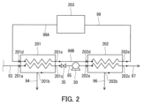
- FIG. 2 is a schematic configuration diagram showing the first condensing section 201 and the second condensing section 202.
- the membrane separation section 10 is omitted.
- the membrane separation system 100 may include a refrigerant path 99 as a flow path for the refrigerant R.
- Refrigerant path 99 has a first portion 99A and a second portion 99B.
- the first part 99A is connected to the refrigerant outlet 202e of the second condensing part 202 and the refrigerant inlet 201d of the first condensing part 201
- the second part 99B is connected to the refrigerant outlet 201e of the first condensing part 201, It may be connected to the refrigerant inlet 202d of the second condensing section 202. That is, the refrigerant R passed through the first condensing section 201 may be configured to be passed through the second condensing section 202. In this way, a common refrigerant R may be used in the first condensing section 201 and the second condensing section 202.
- the membrane separation system 100 may further include a cooling unit 203 for cooling the refrigerant R.
- Cooling unit 203 is typically a chiller.
- the cooling unit 203 may be provided in the first portion 99A of the refrigerant path 99.
- the cooling unit 203 can cool the refrigerant R passed through the first condensing unit 201 and the second condensing unit 202 .
- a temperature sensor that measures the temperature of the refrigerant R may be disposed in the refrigerant path 99.
- a temperature sensor that measures the temperature of the refrigerant R may be disposed in each of the first portion 99A and the second portion 99B. Based on the measurement result of the temperature sensor, the temperature of the refrigerant R passed through the first condensing section 201 and the second condensing section 202 may be controlled so as to satisfy T 1 ⁇ T 2 .
- a pump that controls the flow rate of the refrigerant R may be disposed in the refrigerant path 99.
- a pump may not be disposed in the refrigerant path 99.
- the membrane separation system 100 may further include a pressure regulating valve 35 between the first condensing section 201 and the pressure reducing section 30 to adjust the pressure in the permeation space of the membrane separation section 10.
- a pressure regulating valve 35 between the first condensing section 201 and the pressure reducing section 30 to adjust the pressure in the permeation space of the membrane separation section 10.
- methods for adjusting the pressure in the permeation space of the membrane separation section 10 include a method of introducing outside air into the pressure reducing section 30, and a method of regulating the flow rate using a pressure regulating valve provided upstream of the pressure reducing section 30.
- the membrane separation system 100 may further include pressure sensors (not shown) that measure the pressure P 1 in the first condensing section 201 and the pressure P 2 in the second condensing section 202, respectively.
- the operation of the pressure reducing unit 30 may be controlled based on the measurement result of the pressure sensor so that P 1 ⁇ P 2 is satisfied.
- the membrane separation system 100 may further include a temperature sensor (not shown) that measures each of the cooling temperature T 1 of the first condensing section 201 and the cooling temperature T 2 of the second condensing section 202.
- the operation of the cooling unit 203 may be controlled based on the measurement result of the temperature sensor so that T 1 ⁇ T 2 is satisfied.
- the membrane separation system 100 further includes a tank 40 along with a membrane separation section 10, a first condensation section 201, a pressure reduction section 30, and a second condensation section 202.
- the tank 40 stores the feed liquid S to be supplied to the membrane separation unit 10.
- Tank 40 may be a fermenter for producing organic compound C by fermentation of a carbon source by microorganisms.
- the membrane separation system 100 includes a fermented liquid supply path 91, a non-permeated fluid discharge path 92, a first permeated fluid discharge path 93, a first condensed fluid discharge path 94, a second permeated fluid discharge path 95, and a second permeated fluid discharge path 95 as fluid paths. 2 condensed fluid discharge passages 96 are further provided.
- the fermentation liquid supply path 91 is a path for supplying the supply liquid S from the tank 40 to the membrane separation unit 10 during operation, and is connected to the outlet 40b of the tank 40 and the fermentation liquid inlet 13a of the membrane separation unit 10. ing.
- the non-permeable fluid discharge path 92 is a path for discharging the non-permeable fluid S 2 from the membrane separation section 10 during operation, and is connected to the supply space outlet 13b of the membrane separation section 10.
- a pump for controlling the flow rate of the non-permeable fluid S 2 may be disposed in the non-permeable fluid discharge path 92 .
- a pump may not be disposed in the non-permeable fluid discharge path 92.
- Non-permeate fluid discharge path 92 is connected to inlet 40a of tank 40 and may be configured to deliver non-permeate fluid S2 to tank 40 during operation. That is, during operation, the non-permeable fluid S 2 may be mixed with the supply liquid S in the tank 40 and circulated through the fermentation liquid supply path 91 and the non-permeable fluid discharge path 92 .
- the non-permeate fluid S 2 is sent to the tank 40, the feed liquid S and the non-permeate fluid S 2 are mixed in the tank 40, and the content of organic compound C in the feed liquid S is reduced.
- the tank 40 is a fermenter, the content rate of organic compound C in the supply liquid S decreases, thereby preventing fermentation by microorganisms from stopping, and thereby making it possible to continuously produce fermented products. can.
- the first permeate fluid discharge path 93 is a path for discharging gaseous permeate fluid S 1 from the membrane separation section 10 during operation, and connects the permeation space outlet 14 b of the membrane separation section 10 and the permeation fluid S 1 of the first condensation section 201 .
- the fluid inlet 201a is connected to the fluid inlet 201a.
- the first condensed fluid discharge path 94 is a path for discharging the first condensed fluid S31 from the first condensing section 201 during operation, and is connected to the first condensed fluid outlet 201b of the first condensing section 201. .
- the second permeate fluid discharge path 95 is a path for discharging gaseous permeate fluid S 1 that could not be condensed due to the presence of gas G from the first condensing section 201 during operation. It is connected to the permeate fluid outlet 201c and the permeate fluid inlet 202a of the second condensing section 202.
- the second condensed fluid discharge path 96 is a path for discharging the second condensed fluid S32 from the second condensing section 202 during operation, and is connected to the second condensed fluid outlet 202b of the second condensing section 202. .
- a pressure reducing section 30 is arranged in the second permeate fluid discharge path 95.
- a pressure regulating valve 35 may be disposed between the first condensing section 201 and the pressure reducing section 30.
- a flow meter may be disposed in the first condensed fluid discharge path 94 to measure the flow rate of the first condensed fluid S 31 .
- a flow meter may be disposed in the second condensed fluid discharge path 96 to measure the flow rate of the second condensed fluid S32 .
- the membrane separation system 100 may further include a recovery section 50.
- the recovery unit 50 recovers the first condensed fluid S 31 sent from the first condensation unit 201 and the second condensed fluid S 32 sent from the second condensation unit 202 . 2 condensate fluid S 32 can be stored.
- the recovery unit 50 is, for example, a tank that stores the first condensed fluid S 31 and the second condensed fluid S 32 .
- the first condensed fluid discharge path 94 is connected to the inlet 50a of the recovery section 50
- the second condensed fluid discharge path 96 is connected to the inlet 50b of the recovery section 50.
- the recovery unit 50 may be configured to separately recover and store the first condensed fluid S 31 and the second condensed fluid S 32 .
- the recovery unit 50 recovers the first condensed fluid S 31 sent from the first condensation unit 201 and includes, for example, a tank that can store the first condensed fluid S 31 and a tank that can store the first condensed fluid S 31 and the first condensed fluid S 31 sent from the second condensation unit 202 .
- the second condensed fluid S 32 may be recovered and, for example, a tank capable of storing the second condensed fluid S 32 .
- the membrane separation system 100 further includes a discharge path 97 as a fluid path.
- the exhaust path 97 is connected to the exhaust outlet 202c of the second condensing section 202.
- the membrane separation system 100 may further include a control unit 60 that controls each member of the membrane separation system 100.
- the control unit 60 is, for example, a DSP (Digital Signal Processor) including an A/D conversion circuit, an input/output circuit, an arithmetic circuit, a storage device, and the like.
- the control unit 60 stores a program for appropriately operating the membrane separation system 100.
- the control unit 60 can control the operation of the pressure reducing unit 30 so that P 1 ⁇ P 2 is satisfied during operation.
- the control unit 60 can control the operation of the cooling unit 203 so that T 1 ⁇ T 2 is satisfied.
- each path of the membrane separation system 100 is configured with, for example, metal or resin piping.
- FIG. 3 is a schematic cross-sectional view showing an example of the membrane separation section 10.
- the membrane separation unit 10 includes a pervaporation membrane 11 and a container 12.
- the container 12 has a first chamber 13 and a second chamber 14.
- the first chamber 13 functions as a supply space where the supply liquid S is supplied.
- the second chamber 14 functions as a permeation space to which the permeation fluid S 1 is supplied.
- the permeate fluid S 1 is obtained by permeating the feed liquid S through the pervaporation membrane 11 .
- the pervaporation membrane 11 is placed inside the container 12. Inside the container 12, the pervaporation membrane 11 separates a first chamber 13 and a second chamber 14. The pervaporation membrane 11 extends from one of the pair of walls of the container 12 to the other.
- the first chamber 13 has a supply space inlet 13a and a supply space outlet 13b.
- the second chamber 14 has a permeation space outlet 14b.
- the supply space inlet 13a is an opening for supplying the supply liquid S to the supply space (first chamber 13).
- the permeation space outlet 14b is an opening for discharging the permeation fluid S1 from the permeation space (second chamber 14).
- the supply space outlet 13b is an opening for discharging the supply liquid S (non-permeable fluid S 2 ) that has not passed through the pervaporation membrane 11 from the supply space (first chamber 13).
- Each of the supply space inlet 13a, the supply space outlet 13b, and the permeation space outlet 14b is formed on the wall surface of the container 12, for example.
- the membrane separation unit 10 is suitable for a flow type (continuous type) membrane separation method. However, the membrane separation unit 10 may be used in a batch-type membrane separation method.
- the pervaporation membrane 11 is typically a membrane (separation membrane) that allows the organic compound C contained in the supply liquid S to permeate preferentially.
- the pervaporation membrane 11 generates a gaseous permeate fluid S 1 containing the organic compound C by, for example, a pervaporation method.
- the pervaporation membrane 11 includes, for example, a separation functional layer 1 and a porous support 2 that supports the separation functional layer 1.
- the pervaporation membrane 11 may further include a protective layer (not shown) that protects the separation functional layer 1.
- the separation functional layer 1 is in direct contact with the porous support 2, for example.
- the pervaporation membrane 11 has a main surface 11a on the separation functional layer side exposed to the first chamber 13, and a main surface 11b on the porous support side exposed to the second chamber 14.
- the separation functional layer 1 is typically a layer through which the organic compound C contained in the supply liquid S can preferentially permeate.
- the separation functional layer 1 includes, for example, a hydrophobic material.
- a hydrophobic material means, for example, that when a 10 ⁇ L water droplet (temperature 25°C) is dropped on the surface of a test piece made of the material, the static contact angle of water exceeds 90°. means material. Note that the static contact angle of water can be measured using a commercially available contact angle meter.
- hydrophobic material examples include compounds having siloxane bonds (Si-O-Si bonds), olefin polymers, oils, fluorine compounds, and the like. It is preferable that the separation functional layer 1 contains a compound having a siloxane bond as a hydrophobic material.
- the compound having a siloxane bond is typically a silicone-based polymer.
- the silicone polymer may be solid or liquid at 25°C.
- Specific examples of silicone polymers include polydimethylsiloxane (PDMS).
- olefin polymers include polyethylene and polypropylene.
- oil examples include hydrocarbon oils such as liquid paraffin.
- fluorine-based compound examples include polytetrafluoroethylene (PTFE), polyvinylidene fluoride (PVDF), and tetrafluoroethylene-perfluoroalkyl vinyl ether copolymer (PFA). Hydrophobic materials can be used alone or in combination of two or more.
- the separation functional layer 1 may contain a hydrophobic material as a main component, or may be substantially composed only of a hydrophobic material.
- "Main component” means the component contained in the separation functional layer 1 in the largest amount by weight.
- the separation functional layer 1 may include a matrix containing a hydrophobic material and a filler dispersed in the matrix.
- the filler is embedded within the matrix. Within the matrix, all fillers may be spaced apart from each other or may be partially aggregated.
- the filler includes, for example, inorganic materials such as zeolite, silica, and bentonite.
- the zeolite contained in the filler is preferably a high-silica zeolite with a high ratio of silica to alumina.
- High silica zeolite has excellent hydrolysis resistance and is therefore suitable for use in separating the feed liquid S.
- HSZ registered trademark
- HiSiv registered trademark
- USKY manufactured by Union Showa Co., Ltd.
- Zeoal registered trademark
- the filler may include a metal-organic-framework (MOF).
- the metal-organic framework is also called a porous coordination polymer (PCP).
- PCP porous coordination polymer
- the metal-organic framework is hydrophobic.
- Metal-organic frameworks include, for example, metal ions and organic ligands. Examples of metal ions include Zn ions.
- the organic ligand includes, for example, an aromatic ring. Examples of the aromatic ring contained in the organic ligand include an imidazole ring. Examples of the organic ligand include 2-methylimidazole and the like. Specific examples of the metal-organic framework include ZIF-8 and the like.
- the shape of the filler is, for example, particulate.
- "particulate” includes spherical, ellipsoidal, scaly, and fibrous.
- the average particle size of the filler is not particularly limited, and is, for example, 50 ⁇ m or less, preferably 20 ⁇ m or less, and more preferably 10 ⁇ m or less.
- the lower limit of the average particle size of the filler is, for example, 0.01 ⁇ m.
- the average particle size of the filler can be determined, for example, by the following method. First, a cross section of the separation functional layer 1 is observed using a transmission electron microscope. In the obtained electron microscope image, the area of a specific filler is calculated by image processing.
- the diameter of a circle having the same area as the calculated area is regarded as the particle size (particle diameter) of that particular filler.
- the particle diameters of an arbitrary number of fillers (at least 50) are calculated, and the average value of the calculated values is regarded as the average particle diameter of the fillers.
- the filler content in the separation functional layer 1 is, for example, 10 wt% or more, preferably 30 wt% or more, and more preferably 40 wt% or more.
- the upper limit of the filler content in the separation functional layer 1 is not particularly limited, and is, for example, 70 wt%.
- the content of the matrix in the separation functional layer 1 is not particularly limited, and is, for example, 30 wt% to 90 wt%.
- the thickness of the separation functional layer 1 is, for example, 200 ⁇ m or less, preferably 100 ⁇ m or less, and more preferably 80 ⁇ m or less.
- the thickness of the separation functional layer 1 may be 1.0 ⁇ m or more, 10 ⁇ m or more, or 30 ⁇ m or more.
- the separation functional layer 1 may have a microporous structure with an average pore diameter of less than 0.01 ⁇ m, but it may also be a dense layer with no pores on the surface.
- porous support 2 examples include nonwoven fabric; porous polytetrafluoroethylene; aromatic polyamide fiber; porous metal; sintered metal; porous ceramic; porous polyester; porous nylon; activated carbon fiber; latex silicone; silicone rubber; permeable material containing at least one selected from the group consisting of polyvinyl fluoride, polyvinylidene fluoride, polyurethane, polypropylene, polyethylene, polystyrene, polycarbonate, polysulfone, polyetheretherketone, polyacrylonitrile, polyimide, and polyphenylene oxide. (porous) polymers; metal foams with open or closed cells; polymer foams with open or closed cells; silica; porous glass; mesh screens, and the like.
- the porous support 2 may be a combination of two or more of these.
- the porous support 2 has an average pore diameter of, for example, 0.01 to 0.4 ⁇ m.
- the thickness of the porous support 2 is not particularly limited, and is, for example, 10 ⁇ m or more, preferably 50 ⁇ m or more, and more preferably 100 ⁇ m or more.
- the thickness of the porous support 2 is, for example, 300 ⁇ m or less, preferably 200 ⁇ m or less.
- the protective layer covers the surface of the separation functional layer 1, for example.
- the material for the protective layer is not particularly limited, and examples thereof include silicone resin.
- the material of the protective layer may be the same as the material of the matrix of the separation functional layer 1.
- the thickness of the protective layer is not particularly limited, and is, for example, 0.5 ⁇ m or more, preferably 1 ⁇ m or more, more preferably 5 ⁇ m or more, and still more preferably 10 ⁇ m or more.
- the thickness of the protective layer is, for example, 100 ⁇ m or less, preferably 50 ⁇ m or less, and more preferably 30 ⁇ m or less.
- the pervaporation membrane 11 can be produced, for example, by forming the separation functional layer 1 on the porous support 2. Specifically, first, a coating liquid containing the material of the separation functional layer 1 is prepared. The coating liquid may contain a dispersant for dispersing the filler in the coating liquid together with the filler. When the coating liquid contains a compound having a siloxane bond, the coating liquid may further contain a catalyst for curing the compound. Next, the coating liquid is applied onto the porous support 2 to obtain a coating film. The separation functional layer 1 is formed by drying the coating film.
- the method of operating the membrane separation system 100 is to separate a feed liquid S containing a volatile organic compound C and a gas G into a permeate fluid S 1 and a non-permeate fluid S 2 by the pervaporation membrane of the membrane separation unit 10.
- Step 1 the first condensing section 201 condenses the organic compound C contained in the permeate fluid S 1 discharged from the membrane separation section 10
- Step 2 the second condensing section 202 condenses the organic compound C contained in the permeate fluid S1 discharged from the membrane separation section 10; condensing the organic compound C contained in the permeate fluid S 1 discharged from 30 (step 3).
- Step 1 includes reducing the pressure in the permeation space of the membrane separation unit 10 by the pressure reduction unit 30.
- the feed liquid S when the feed liquid S is a fermentation liquid, the feed liquid S contains a volatile organic compound C and a microorganism that produces the organic compound C.
- the feed liquid S contains water in addition to the organic compound C, microorganisms, and gas G, for example.
- the feed liquid S is typically an aqueous solution containing an organic compound C, a microorganism, and a gas G.
- the organic compound C contained in the supply liquid S is not particularly limited as long as it has volatility.
- a volatile organic compound means, for example, an organic compound having a boiling point of 20° C. to 260° C. under atmospheric pressure (101.325 kPa). Note that, for example, when the organic compound C has a high concentration in an aqueous solution, it produces an aqueous phase containing water as a main component and an organic phase having a higher content of organic compound C than the aqueous phase. be.
- the number of carbon atoms in the organic compound C is not particularly limited, and may be, for example, 10 or less, 8 or less, 6 or less, or even 4 or less.
- the lower limit of the number of carbon atoms in the organic compound C may be 1 or 2.
- the organic compound C has a functional group containing an oxygen atom, such as a hydroxyl group, a carbonyl group, an ether group, or an ester group. In organic compound C, the number of functional groups containing an oxygen atom is typically one.
- Examples of the organic compound C include alcohol, ketone, ester, etc., and alcohol is preferable.
- the organic compound C is alcohol, the organic compound C is easily compatible with water, and the environment within the system is less likely to be biased.
- the alcohol may be an alkyl alcohol composed only of an alkyl group and a hydroxyl group, or an aryl alcohol containing an aryl group and a hydroxyl group.
- the alkyl alcohol may be linear, branched, or cyclic.
- alkyl alcohol examples include methanol, ethanol, n-propanol, isopropanol, n-butanol, 2-butanol, isobutanol, t-butanol, and n-pentanol, with n-butanol being preferred.
- N-butanol is a compound that produces two phases (aqueous phase and organic phase) from an aqueous solution when its content in the aqueous solution is about 8 wt% or more.
- the organic compound C is n-butanol
- the aqueous phase and the organic phase can be mixed in the first condensed fluid S 31 .
- the first condensed fluid S 31 can be easily purified by separating the aqueous phase and the organic phase.
- the aryl alcohol include phenol.
- the ketone may be a dialkyl ketone composed only of an alkyl group and a carbonyl group.
- dialkyl ketones include methyl ethyl ketone (MEK) and acetone.
- the ester may be a fatty acid alkyl ester composed only of an alkyl group and an ester group.
- fatty acid alkyl esters include ethyl acetate.
- organic compound C is not limited to those mentioned above.
- the organic compound C may be an aromatic hydrocarbon such as benzene, toluene, or xylene.
- the supply liquid S may contain one type of organic compound C, or may contain two or more types of organic compound C.
- the content of the organic compound C in the supply liquid S is, for example, 50 wt% or less, and may be 30 wt% or less, 10 wt% or less, 5 wt% or less, 2 wt% or less, or even 1 wt% or less.
- the lower limit of the content of organic compound C is not particularly limited, and is, for example, 0.01 wt%.
- the organic compound C may be a fermented product produced by fermentation of a carbon source by microorganisms.
- the organic compound C is preferably an alcohol produced by microorganisms (bioalcohol).
- the feed liquid S may further contain other components such as a carbon source, a nitrogen source, and inorganic ions.
- carbon sources include polysaccharides such as starch and monosaccharides such as glucose.
- step 1 A specific implementation method of step 1 will be explained using the membrane separation unit 10 shown in FIG. 3 as an example.
- the supply liquid S is supplied to the first chamber 13 of the membrane separation section 10 through the supply space inlet 13a. Thereby, the supply liquid S can be brought into contact with one surface (for example, the main surface 11a) of the pervaporation membrane 11.
- the pressure in the space adjacent to the other surface (for example, the main surface 11b) of the pervaporation membrane 11 is reduced.
- the pressure inside the second chamber 14 is reduced through the permeation space outlet 14b.
- the pressure inside the second chamber 14 can be reduced by the pressure reducing section 30.
- the pressure in the second chamber 14 is, for example, 50 kPa or less, and may be 20 kPa or less, 10 kPa or less, 5 kPa or less, 3 kPa or less, or even 2 kPa or less.
- the permeate fluid S 1 is supplied to the second chamber 14 .
- the permeate fluid S 1 is typically a gas.
- the permeate fluid S 1 is discharged to the outside of the membrane separation section 10 through the permeate space outlet 14b.
- the permeate fluid S 1 is supplied to the first condensing section 201 through the permeate fluid inlet 201a via the first permeate discharge path 93.
- Non-permeate fluid S 2 is discharged to the outside of the membrane separation section 10 through the supply space outlet 13b.
- Non-permeable fluid S2 is typically a liquid.
- Non-permeate fluid S 2 is supplied to tank 40 through inlet 40a via non-permeate fluid discharge path 92.
- step 1 the organic compound C contained in the supply liquid S can be preferentially permeated through the pervaporation membrane 11 of the membrane separation unit 10. Therefore, the permeate fluid S 1 obtained by the operation of the membrane separation section 10 has a higher content of organic compounds C than the feed liquid S supplied to the membrane separation section 10 .
- the ratio of the content (wt%) of organic compound C in the permeate fluid S1 to the content (wt%) of organic compound C in feed liquid S is not particularly limited.
- step 1 for example, a permeate fluid S 1 having a high content of organic compounds C can be produced.
- the organic compound C can be obtained as the permeate fluid S 1 .
- Step 1 includes reducing the pressure in the permeation space of the membrane separation unit 10 by the pressure reduction unit 30.
- the operation of the pressure reducing section 30 may be controlled so that P 1 ⁇ P 2 is satisfied during operation.
- step 2 A specific implementation method of step 2 will be described using the first condensing section 201 shown in FIG. 2 as an example.
- step 2 first, the permeate fluid S 1 is supplied to the first condensing section 201 through the permeate fluid inlet 201a.
- the permeate fluid S 1 contains gas G.
- the refrigerant R is passed through the first condensing section 201 through the refrigerant inlet 201d. Therefore, within the first condensing section 201, heat exchange is performed between the refrigerant R and the gaseous permeate fluid S1 . This cools the gaseous permeate fluid S 1 and condenses the organic compound C.
- the first condensed fluid S 31 containing the organic compound C is discharged from the first condensing section 201 through the first condensed fluid outlet 201b.
- the permeate fluid S 1 that could not be condensed due to the presence of the gas G is discharged from the first condensing section 201 through the permeate outlet 201c.
- step 3 the permeated fluid S 1 discharged from the first condensing section 201 is supplied to the second condensing section 202 through the permeated fluid inlet 202 a as exhaust from the pressure reducing section 30 .
- the refrigerant R is passed through the second condensing section 202 through the refrigerant inlet 202d. Therefore, within the second condensing section 202, heat exchange is performed between the refrigerant R and the gaseous permeate fluid S1 . This cools the gaseous permeate fluid S 1 and condenses the organic compound C.
- the second condensed fluid S 32 containing the organic compound C is discharged from the second condensing section 202 through the second condensed fluid outlet 202b. The remaining exhaust gas is exhausted from the second condensing section 202 through the exhaust outlet 202c.
- the amount of permeate fluid S1 discharged outside the system can be reduced, thereby suppressing a decrease in condensation efficiency.
- the recovery efficiency of organic compound C is improved.
- the method for producing an organic compound of this embodiment is a method for producing an organic compound using the membrane separation section 10, the pressure reduction section 30, the first condensation section 201, and the second condensation section 202.
- the first condensing section 201 is arranged between the membrane separation section 10 and the pressure reducing section 30.
- a pervaporation membrane in a membrane separation unit 10 separates a feed liquid S containing a volatile organic compound C and a gas G into a permeate fluid S 1 and a non-permeate fluid S 2 .
- the first condensing section 201 condenses the organic compound C contained in the permeated fluid S 1 discharged from the membrane separation section 10
- the second condensing section 202 condenses the permeated fluid S 1 discharged from the pressure reducing section 30 .
- the method includes condensing the organic compound C contained in the fluid S 1 and recovering the organic compound C.
- the above-mentioned separation includes reducing the pressure in the permeation space of the membrane separation unit 10 by the pressure reduction unit 30.
- the organic compound C may be alcohol. According to the method for producing an organic compound of the present embodiment, alcohol can be efficiently separated from the supply liquid S 0 containing volatile alcohol.
- the membrane separation unit 10 may be a spiral type membrane element, a hollow fiber membrane element, a disk tube type membrane element in which a plurality of pervaporation membranes are stacked, a plate and frame type membrane element, or the like.
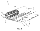
- FIG. 5 is an exploded perspective view schematically showing a spiral membrane element.
- the membrane separation unit 10 may be a spiral type membrane element as shown in FIG.
- the membrane separation unit 10 (membrane element) in FIG. 5 includes a central tube 16 and a membrane leaf 17 having a pervaporation membrane 11 and wound around the central tube 16.
- the central tube 16 has a cylindrical shape.
- a through hole 16h is formed on the surface of the center tube 16 for allowing the permeate fluid S 1 to flow into the center tube 16.
- the number of through holes 16h is not particularly limited, and may be one or two or more.
- materials for the center tube 16 include resins such as acrylonitrile-butadiene-styrene copolymer resin (ABS resin), polyphenylene ether resin (PPE resin), and polysulfone resin (PSF resin); metals such as stainless steel and titanium. It will be done.
- the inner diameter of the central tube 16 is, for example, in the range of 20 to 100 mm.
- the membrane separation unit 10 has a plurality of membrane leaves 17.
- Each membrane leaf 17 includes a pervaporation membrane 11 and a permeate channel material 19 .
- membrane leaf 17 has two pervaporation membranes 11. Two pervaporation membranes 11 are stacked on top of each other and sealed on three sides to form a bag-like structure.
- a permeate-side channel material 19 is arranged between the two pervaporation membranes 11 so as to be located inside the bag-like structure.
- the permeation side channel material 19 secures a space (permeation space) between the two pervaporation membranes 11 as a flow path for the permeate fluid S1. In this way, the permeate side channel material 19 is used in combination with the pervaporation membrane 11.
- the number of membrane leaves 17 is not particularly limited, and is, for example, 2 to 30.
- the membrane separation unit 10 further includes a supply side channel material 18.
- the supply side channel material 18 is located outside the bag-like structure described above and is laminated on the membrane leaf 17. Specifically, a plurality of supply side channel materials 18 and a plurality of membrane leaves 17 are alternately stacked.
- the supply side channel material 18 secures a space (supply space) as a channel for the supply liquid S between the membrane leaves 17 .
- the supply side channel material 18 and the permeate side channel material 19 are made of resin made of polyethylene, polypropylene, polyethylene terephthalate (PET), polyphenylene sulfide (PPS), or ethylene-chlorotrifluoroethylene copolymer (ECTFE), for example. Nets, woven or knitted fabrics can be used.
- the outer peripheral surface of the membrane element is composed of a shell (not shown) made of a material through which fluid cannot pass.
- the shell may be made of FRP (fiber reinforced plastic).
- the membrane element may be housed in a casing (not shown).
- the membrane separation section 10 (membrane element) in FIG. 5 can be operated, for example, in the following manner.
- the supply liquid S is supplied to one end of the wound membrane leaf 17.
- the space inside the central tube 16 is depressurized.
- the pressure reduction can be performed by the pressure reduction section 30.
- the permeated fluid S 1 that has passed through the pervaporation membrane 11 of the membrane leaf 17 moves into the center tube 16 .
- the permeate fluid S 1 is discharged to the outside through the central tube 16 .
- the feed liquid S (non-permeate fluid S 2 ) treated in the membrane separation unit 10 is discharged to the outside from the other end of the wound membrane leaf 17 .
- the membrane separation system 100 of this embodiment may include a plurality of membrane separation units 10, and the plurality of membrane separation units 10 may be connected to each other in series or in parallel.
- a plurality of membrane separation units 10 are connected in series means that the feed liquid S discharged from the supply space of the membrane separation unit 10 in the previous stage (non-permeable during operation of the membrane separation system) This refers to a configuration in which a plurality of membrane separation units 10 are connected to each other so that the fluid S 2 ) is supplied to the supply space of the membrane separation unit 10 at the subsequent stage.
- a plurality of membrane separation units 10 are connected in parallel to each other means that a plurality of membrane separation units 10 are connected in parallel so that the supply liquid S sent from the tank 40 is supplied to each supply space of the plurality of membrane separation units 10. This refers to a configuration in which the separation parts 10 are connected to each other.
- the number of membrane separation units 10 in the membrane separation system 100 is not particularly limited, and is, for example, 2 to 5.
- the membrane separation system 100 of this embodiment may include a plurality of units each having a plurality of directly connected membrane separation sections 10, and may have a configuration in which each unit is connected in parallel.
- the membrane separation system 100 may include two units each having three directly connected membrane separation sections 10, and the two units may be connected in parallel.
- a pervaporation membrane was prepared by the following method. Silicone resin (YSR3022 manufactured by Momentive Performance Materials Japan) 1.650 kg (solid concentration 30 wt%), toluene 2.805 kg, high silica zeolite (HiSiv3000 manufactured by Union Showa Co., Ltd.) 0.495 kg, silicone curing catalyst A coating liquid was prepared by mixing 0.0495 kg of YC6831 (manufactured by Momentive Performance Materials Japan) and 0.0495 kg of acetylacetone as a curing retarder.
- a coating film (thickness: 500 ⁇ m) was obtained by applying the coating solution onto a porous support (RS-50, manufactured by Nitto Denko Corporation) with a thickness of 150 ⁇ m.
- the coating film was heated at 90° C. for 4 minutes and dried to produce a separation functional layer with a thickness of 50 ⁇ m.
- the weight ratio of silicone resin and high silica zeolite was 50:50. Thereby, a pervaporation membrane was obtained.
- the membrane separation system 200 includes a first heat exchanger 301 in place of the first condensation section 201, a second heat exchanger 302 in place of the second condensation section 202, and a recovery section 50 in the second heat exchanger. It had the same configuration as the membrane separation system 100 shown in FIG. 1, except that it was connected only to the vessel 302.
- the first heat exchanger 301 only functions as a heat exchanger, and is configured to cool the gaseous permeate fluid S 1 discharged from the membrane separation unit 10 but not to condense it.
- the second heat exchanger 302 was configured to condense the gaseous permeate fluid S 1 discharged from the first heat exchanger 301 under atmospheric pressure.
- the aqueous solution sent from the tank 40 to the membrane separation unit 10 contains alcohol (n-butanol or ethanol) and gas G as volatile organic compounds.
- alcohol n-butanol or ethanol
- gas G volatile organic compounds.
- the membrane separation system 100 included a membrane separation section 10, a pressure reduction section 30, a first condensation section 201, a second condensation section 202, and the like.
- the feed liquid sent from the tank 40 to the membrane separation unit 10 contains alcohol (n-butanol or ethanol) and volatile organic compounds.
- the permeate fluid S 1 containing gas G is obtained by reducing the pressure in the permeation space of the membrane separation unit 10 by the decompression unit 30 , and the obtained permeate fluid S 1 is transferred to the first condensing unit 201 . It was assumed that the alcohol was condensed by cooling, and that the permeate fluid S 1 that could not be condensed in the first condensing section 201 was further cooled in the second condensing section 202 to condense the alcohol.
- Table 2 shows the simulation results for calculation examples 1 to 10.
- n-butanol is condensed by cooling the permeate fluid S 1 in the first condensing section 201;
- the recovery rate of n-butanol was greatly improved.
- the membrane separation system 100 shown in FIG. 1 compared to the membrane separation system 200 shown in FIG. 6 and the conventional membrane separation system 1000 shown in FIG. Therefore, the reduction in condensation efficiency was suppressed. This result shows that the membrane separation system of this embodiment, which is capable of two-stage condensation, is suitable for efficiently recovering organic compounds.
- the membrane separation system of this embodiment is suitable for efficiently recovering organic compounds.
Landscapes
- Engineering & Computer Science (AREA)
- Water Supply & Treatment (AREA)
- Chemical & Material Sciences (AREA)
- Chemical Kinetics & Catalysis (AREA)
- Separation Using Semi-Permeable Membranes (AREA)
Priority Applications (4)
| Application Number | Priority Date | Filing Date | Title |
|---|---|---|---|
| EP23865243.2A EP4588552A1 (en) | 2022-09-14 | 2023-08-25 | Membrane separation system, and method for operating membrane separation system |
| US19/106,292 US20260061371A1 (en) | 2022-09-14 | 2023-08-25 | Membrane separation system and method for operating membrane separation system |
| JP2024546821A JPWO2024057886A1 (https=) | 2022-09-14 | 2023-08-25 | |
| CN202380063915.4A CN119836321A (zh) | 2022-09-14 | 2023-08-25 | 膜分离系统及膜分离系统的运转方法 |
Applications Claiming Priority (2)
| Application Number | Priority Date | Filing Date | Title |
|---|---|---|---|
| JP2022146504 | 2022-09-14 | ||
| JP2022-146504 | 2022-09-14 |
Publications (1)
| Publication Number | Publication Date |
|---|---|
| WO2024057886A1 true WO2024057886A1 (ja) | 2024-03-21 |
Family
ID=90274997
Family Applications (1)
| Application Number | Title | Priority Date | Filing Date |
|---|---|---|---|
| PCT/JP2023/030827 Ceased WO2024057886A1 (ja) | 2022-09-14 | 2023-08-25 | 膜分離システム及び膜分離システムの運転方法 |
Country Status (5)
| Country | Link |
|---|---|
| US (1) | US20260061371A1 (https=) |
| EP (1) | EP4588552A1 (https=) |
| JP (1) | JPWO2024057886A1 (https=) |
| CN (1) | CN119836321A (https=) |
| WO (1) | WO2024057886A1 (https=) |
Citations (6)
| Publication number | Priority date | Publication date | Assignee | Title |
|---|---|---|---|---|
| JPH01107805A (ja) * | 1987-10-22 | 1989-04-25 | Mitsubishi Heavy Ind Ltd | 廃溶剤の精製回収法 |
| JPH025849A (ja) * | 1988-02-11 | 1990-01-10 | Gft G Fuer Trentechnik Mbh | アルコール飲料のアルコール分低減法及び装置 |
| JP2006042673A (ja) * | 2004-08-04 | 2006-02-16 | National Institute Of Advanced Industrial & Technology | 発酵エタノールの膜分離精製システム |
| JP4048279B2 (ja) | 2004-02-24 | 2008-02-20 | 独立行政法人産業技術総合研究所 | 発酵エタノール分離精製システム |
| CN111203109A (zh) * | 2020-01-15 | 2020-05-29 | 南京工业大学 | 一种渗透汽化循环换热新系统及方法 |
| JP2020146639A (ja) * | 2019-03-14 | 2020-09-17 | オルガノ株式会社 | 有機溶剤の脱水装置及び脱水方法 |
-
2023
- 2023-08-25 JP JP2024546821A patent/JPWO2024057886A1/ja active Pending
- 2023-08-25 WO PCT/JP2023/030827 patent/WO2024057886A1/ja not_active Ceased
- 2023-08-25 EP EP23865243.2A patent/EP4588552A1/en active Pending
- 2023-08-25 CN CN202380063915.4A patent/CN119836321A/zh active Pending
- 2023-08-25 US US19/106,292 patent/US20260061371A1/en active Pending
Patent Citations (6)
| Publication number | Priority date | Publication date | Assignee | Title |
|---|---|---|---|---|
| JPH01107805A (ja) * | 1987-10-22 | 1989-04-25 | Mitsubishi Heavy Ind Ltd | 廃溶剤の精製回収法 |
| JPH025849A (ja) * | 1988-02-11 | 1990-01-10 | Gft G Fuer Trentechnik Mbh | アルコール飲料のアルコール分低減法及び装置 |
| JP4048279B2 (ja) | 2004-02-24 | 2008-02-20 | 独立行政法人産業技術総合研究所 | 発酵エタノール分離精製システム |
| JP2006042673A (ja) * | 2004-08-04 | 2006-02-16 | National Institute Of Advanced Industrial & Technology | 発酵エタノールの膜分離精製システム |
| JP2020146639A (ja) * | 2019-03-14 | 2020-09-17 | オルガノ株式会社 | 有機溶剤の脱水装置及び脱水方法 |
| CN111203109A (zh) * | 2020-01-15 | 2020-05-29 | 南京工业大学 | 一种渗透汽化循环换热新系统及方法 |
Also Published As
| Publication number | Publication date |
|---|---|
| JPWO2024057886A1 (https=) | 2024-03-21 |
| EP4588552A1 (en) | 2025-07-23 |
| US20260061371A1 (en) | 2026-03-05 |
| CN119836321A (zh) | 2025-04-15 |
Similar Documents
| Publication | Publication Date | Title |
|---|---|---|
| JP6715575B2 (ja) | 二酸化炭素分離方法及び二酸化炭素分離装置 | |
| WO2020203994A1 (ja) | ガス分離システム | |
| US20260084111A1 (en) | Membrane separation system and method for operating membrane separation system | |
| WO2024057886A1 (ja) | 膜分離システム及び膜分離システムの運転方法 | |
| WO2023176565A1 (ja) | 膜分離システム、及び膜分離装置の運転方法 | |
| JP2023137101A (ja) | 膜分離装置の保管方法、及び膜分離システム | |
| WO2024058081A1 (ja) | 膜分離システム及び膜分離システムの運転方法 | |
| WO2023181894A1 (ja) | 膜分離システム、及び膜分離システムの運転方法 | |
| EP4549004A1 (en) | Membrane separation system and method for operating membrane separation device | |
| US20250312741A1 (en) | Membrane separation device, membrane separation system, and method for operating membrane separation device | |
| US20250387759A1 (en) | Membrane separation device, membrane separation system, and method for operating membrane separation device | |
| WO2025225508A1 (ja) | 膜分離システム及び膜分離システムの運転方法 | |
| WO2024004743A1 (ja) | 膜分離システム、及び膜分離装置の洗浄方法 | |
| WO2024190846A1 (ja) | ガス分離システム及び混合ガスの分離方法 | |
| TW202604623A (zh) | 膜分離系統及膜分離系統之運轉方法 | |
| WO2026083812A1 (ja) | 浸透気化膜 | |
| GB2544879A (en) | A device for vapour extraction and capture | |
| WO2024070990A1 (ja) | ガス分離システム | |
| WO2024070575A1 (ja) | 浸透気化膜 | |
| WO2025177856A1 (ja) | ガス分離システム及び混合ガスの分離方法 |
Legal Events
| Date | Code | Title | Description |
|---|---|---|---|
| 121 | Ep: the epo has been informed by wipo that ep was designated in this application |
Ref document number: 23865243 Country of ref document: EP Kind code of ref document: A1 |
|
| WWE | Wipo information: entry into national phase |
Ref document number: 2024546821 Country of ref document: JP |
|
| WWE | Wipo information: entry into national phase |
Ref document number: 202380063915.4 Country of ref document: CN |
|
| REG | Reference to national code |
Ref country code: BR Ref legal event code: B01A Ref document number: 112025004377 Country of ref document: BR |
|
| WWE | Wipo information: entry into national phase |
Ref document number: 202517027187 Country of ref document: IN |
|
| WWP | Wipo information: published in national office |
Ref document number: 202517027187 Country of ref document: IN |
|
| WWE | Wipo information: entry into national phase |
Ref document number: 2023865243 Country of ref document: EP |
|
| NENP | Non-entry into the national phase |
Ref country code: DE |
|
| WWP | Wipo information: published in national office |
Ref document number: 202380063915.4 Country of ref document: CN |
|
| ENP | Entry into the national phase |
Ref document number: 2023865243 Country of ref document: EP Effective date: 20250414 |
|
| WWP | Wipo information: published in national office |
Ref document number: 2023865243 Country of ref document: EP |
|
| ENP | Entry into the national phase |
Ref document number: 112025004377 Country of ref document: BR Kind code of ref document: A2 Effective date: 20250307 |