WO2024057624A1 - 切屑回収システム - Google Patents
切屑回収システム Download PDFInfo
- Publication number
- WO2024057624A1 WO2024057624A1 PCT/JP2023/019084 JP2023019084W WO2024057624A1 WO 2024057624 A1 WO2024057624 A1 WO 2024057624A1 JP 2023019084 W JP2023019084 W JP 2023019084W WO 2024057624 A1 WO2024057624 A1 WO 2024057624A1
- Authority
- WO
- WIPO (PCT)
- Prior art keywords
- chips
- chip collection
- main duct
- air
- air blower
- Prior art date
Links
- 238000007664 blowing Methods 0.000 claims description 32
- 230000000630 rising effect Effects 0.000 claims description 16
- 238000010586 diagram Methods 0.000 description 19
- 230000032258 transport Effects 0.000 description 13
- 238000004590 computer program Methods 0.000 description 12
- 238000011084 recovery Methods 0.000 description 8
- 230000006870 function Effects 0.000 description 6
- 238000000034 method Methods 0.000 description 6
- 230000007246 mechanism Effects 0.000 description 5
- 239000000758 substrate Substances 0.000 description 5
- 238000004891 communication Methods 0.000 description 4
- 238000011144 upstream manufacturing Methods 0.000 description 4
- 239000004065 semiconductor Substances 0.000 description 2
- 230000003247 decreasing effect Effects 0.000 description 1
- 230000010354 integration Effects 0.000 description 1
- 239000000463 material Substances 0.000 description 1
- 230000004048 modification Effects 0.000 description 1
- 238000012986 modification Methods 0.000 description 1
- 230000000149 penetrating effect Effects 0.000 description 1
Images


Classifications
-
- H—ELECTRICITY
- H05—ELECTRIC TECHNIQUES NOT OTHERWISE PROVIDED FOR
- H05K—PRINTED CIRCUITS; CASINGS OR CONSTRUCTIONAL DETAILS OF ELECTRIC APPARATUS; MANUFACTURE OF ASSEMBLAGES OF ELECTRICAL COMPONENTS
- H05K13/00—Apparatus or processes specially adapted for manufacturing or adjusting assemblages of electric components
- H05K13/02—Feeding of components
Definitions
- the present disclosure relates to a chip collection system and a chip collection method for collecting chips of a tape member discharged from a tape feeder.
- a chip collection system that automatically collects chips of a tape member discharged from a tape feeder serving as a component supply unit (for example, Patent Document 1 below).
- the present disclosure provides a chip collection system and a chip collection method that can efficiently collect chips of a tape member into a container that accommodates the chips.
- a chip collection system includes a chip collection path that collects chips of a tape member discharged from a tape feeder provided in a component mounting device and drops the chips that have been moved in a traveling direction;
- the chip collection path includes a chute for passing the chips falling from the road, and a container installed below the chute to store the chips that have passed through the chute, and the chip collection path is configured to use air to direct the chips in the traveling direction. It has an air blower to move it to.
- the chip collection system includes a chip collection path that collects chips of tape materials discharged from a tape feeder provided in a component mounting device and drops the chips moved in the traveling direction, a chute that passes the chips that fall from the chip collection path, a container that is installed below the chute and that contains the chips that have passed through the chute and fallen, and a flexible cover member that is positioned to extend the outlet of the chute.
- chips from the tape member can be efficiently collected into a container that accommodates the chips.
- FIG. 1 is a perspective view showing a chip collection system according to Embodiment 1 together with a work line of a component mounting device.
- FIG. 2 is a side view of the component mounting device in the first embodiment.
- FIG. 3 is a cross-sectional view of a part of the component mounting device and a part of the chip collection system in the first embodiment.
- FIG. 4 is a perspective view of the chip collection system in the first embodiment.
- FIG. 5 is a diagram showing an example of a schematic plan view of the chip collection system in the first embodiment.
- FIG. 6 is a perspective view for explaining the configuration of the recovery section according to the present embodiment.
- FIG. 7 is a cross-sectional view for explaining the configuration of the recovery section according to this embodiment.
- FIG. 8 is a perspective view for explaining the structure of the cover member.
- FIG. 9 is a diagram for explaining the function of the cover member.
- FIG. 10 is a diagram illustrating an example of a control unit and valves to be controlled by the control unit in the first embodiment.
- FIG. 11 is a diagram for explaining a first example of the operation of the chip collection system according to the first embodiment.
- FIG. 12 is a diagram for explaining a second example of the operation of the chip collection system according to the first embodiment.
- FIG. 13 is a diagram for explaining a third example of the operation of the chip collection system according to the present embodiment.
- FIG. 14 is a diagram showing a part of a side view of the chip collection system according to the second embodiment.
- FIG. 15 is a diagram showing an example of a schematic plan view of the chip collection system according to the second embodiment.
- FIG. 16 is a diagram illustrating an example of a control unit and valves to be controlled by the control unit in the second embodiment.
- FIG. 17 is a diagram for explaining an example of the operation of the chip collection system according to the second embodiment.
- FIG. 18 is a cross-sectional view for explaining the configuration of the recovery section when the blower is used as an air blower.
- Patent Document 1 the chips of the tape member are conveyed by a conveyor and discharged into the storage box (container), thereby collecting the chips in the storage box.
- the storage box container
- the chips are conveyed by a conveyor, if the chips are caught or caught on the conveyor, there is a possibility that resistance will occur in the operation of the conveyor. Therefore, there is a risk that the energy efficiency of the conveyor will decrease or a problem will occur in the power source of the conveyor.
- a chip collection system includes a chip collection path that collects chips of a tape member discharged from a tape feeder included in a component mounting device, and drops the chips that have been moved in a traveling direction;
- the chip collection path includes a chute through which the chips falling from the chip collection path pass, and a container installed below the chute to accommodate the chips that have passed through the chute. It has an air blower that moves in the direction of travel.
- the chips are moved by air to the chute in the chip collection path, it is possible to suppress the chips from causing resistance to the power source for moving the chips. Therefore, the chips of the tape member can be efficiently collected into the container that accommodates the chips.
- a chip collection system is the chip collection system according to the first aspect, wherein the chip collection path includes a chip raising and falling section that raises and then drops the collected chips. .
- chips are lifted by air to the entrance of the chute and are dropped at the exit of the chip collection path, so the chips cause resistance to the power source for moving the chips. can be suppressed. Therefore, the chips of the tape member can be efficiently collected into the container that accommodates the chips.
- a chip collection system is the chip collection system according to the first aspect or the second aspect, and is further arranged at a position extending the outlet of the chute and has flexibility.
- a cover member having:
- the cover member can suppress the chips discharged from the outlet of the chute from moving from between the chute and the container to the outside of the container. That is, the cover member can guide the chips into the container. Chips of the tape member can be efficiently collected into a container that accommodates the chips. Moreover, since the cover member has flexibility, even if the container interferes with the cover member when the container is moved in the horizontal direction, the cover member can flex to avoid the container. Therefore, the container can be easily moved. In other words, it is possible to both move the container and suppress the chips that have fallen down the chute from moving out of the container from between the chute and the container.
- a chip collection system is the chip collection system according to the third aspect, in which the cover member is disposed around the outlet of the chute.
- the cover member can suppress the chips that have fallen down the chute from moving out of the container from between the chute and the container.
- a chip collection system is a chip collection system according to the fourth aspect, in which the cover member has a cut extending in the vertical direction.
- the cover member can avoid the container and bend more easily, and the container can be easily moved.
- a chip collection system is a chip collection system according to any one of the first to fifth aspects, further comprising: collecting the chips discharged from the tape feeder.
- a first air blower that moves the chips to the main duct; and a first air blower that blows air toward the outlet of the main duct to transfer the chips that have been moved from the subduct into the main duct through the opening to the main duct.
- a second air blower to be moved to the outlet of the main duct, and the chip collection path collects the chips discharged from the outlet of the main duct.
- the chips are moved by air in the subduct and the main duct up to the chip collection path, the chips can be efficiently collected up to the chip collection path. Therefore, the chips of the tape member can be efficiently collected into the container that accommodates the chips.
- a chip collection system is the chip collection system according to the sixth aspect, in which the chip collection path extends in a direction intersecting the direction in which the main duct extends.
- a chip collection system is a chip collection system according to any one of the first to seventh aspects, wherein the air blower blows air by rotating an impeller. It is a blower that sends out.
- the air blower with a blower that sends out air by rotating the impeller, the blowing of air can be switched on and off by turning the blower on and off, and chips can be conveyed with a simple configuration.
- a chip collection system includes a chip collection path that collects chips of a tape member discharged from a tape feeder included in a component mounting device, and drops the chips that have been moved in a traveling direction; a chute through which the chips falling from the chip collection path pass; a container installed below the chute and accommodating the chips that have passed through the chute; and a container located at a position extending the outlet of the chute; A flexible cover member.
- the cover member can suppress the chips discharged from the outlet of the chute from moving from between the chute and the container to the outside of the container. That is, the cover member can guide the chips into the container. Chips of the tape member can be efficiently collected into a container that accommodates the chips. Moreover, since the cover member has flexibility, even if the container is moved in the horizontal direction and interferes with the cover member, the cover member can bend to avoid the container. Therefore, the container can be easily moved. In other words, it is possible to both move the container and suppress the chips that have fallen down the chute from moving out of the container from between the chute and the container.
- FIG. 1 shows a work line 2 in which a chip collection system 1 according to the present embodiment is installed.
- the work line 2 includes a plurality of (three in this case) component mounting devices 3a to 3c (hereinafter, each of the component mounting devices 3a to 3c is also referred to as component mounting device 3) for mounting components onto the board KB, arranged in one direction.
- Adjacent component mounting apparatuses 3 pass the board KB to each other and mount components on the board KB.
- the direction in which the board KB is delivered in the work line 2 (the left-right direction, the direction in which the component mounting devices 3a to 3c are lined up) is the X direction
- the horizontal direction (front-back direction) perpendicular to the X direction is the Y direction.
- the vertical direction is the Z direction.
- the component mounting device 3 has a base 11 and a cover member 12 that covers the top of the base 11.
- a work space 13 covered by a cover member 12 is formed above the base 11 .
- a substrate transport section 14 is installed on the upper surface of the base 11 and extends in the work space 13 in the X direction.
- the substrate transport section 14 is composed of a pair of conveyor mechanisms arranged in the Y direction.
- the substrate transport unit 14 transports the board KB in the X direction and positions the board KB at a predetermined work position within the work space 13 .
- feeder carts 15 are attached to the front and rear ends of the base 11, respectively.
- a plurality of tape feeders 16 are attached to each feeder truck 15 in line in the X direction (see also FIG. 1).
- Each tape feeder 16 takes in a carrier tape 18 as a tape member unreeled from a tape reel 17 held on a feeder cart 15, transports it in the Y direction (direction toward the substrate transport section 14), and stores the carrier tape 18 in the carrier tape 18.
- Component BH is supplied to component supply position 16K.
- each mounting head 21 includes a nozzle 21N extending downward.
- the head moving mechanism 22 is composed of, for example, a Cartesian coordinate robot, and moves the two mounting heads 21 independently within a horizontal plane.
- Each mounting head 21 picks up the component BH supplied by the tape feeder 16 to the component supply position 16K by adsorbing it to the lower end of the nozzle 21N (FIG. 2).
- the component mounting device 3 includes a control device 23.
- the control device 23 controls the operations of the substrate transport section 14, tape feeder 16, mounting head 21, head moving mechanism 22, and the like.
- the component mounting device 3 When performing component mounting work, the component mounting device 3 first operates the board transport section 14 to receive the board KB from the upstream device and positions it at a working position. After positioning the board KB at the work position, the component mounting device 3 operates the tape feeder 16 to supply the component BH to the component supply position 16K, and operates the head moving mechanism 22 to transfer the component to the mounting head 21. Have them do it repeatedly. In the component transfer work, the mounting head 21 picks up the component BH supplied by the tape feeder 16 and then mounts the component BH onto the board KB.
- each component mounting device 3 After each component mounting device 3 mounts the component BH to be mounted on the board KB by repeatedly carrying out the component transfer operation using the mounting head 21, it operates the board transport section 14 to transport the board KB to the downstream side. . As a result, each of the three component mounting devices 3 mounts the component BH on the board KB, and when the component mounting device 3 located on the most downstream side carries out the board KB, the component mounting work on the board KB by the work line 2 ends. do.
- the feeder truck 15 included in each component mounting device 3 includes a tape cutter 24 and a shooter 25.
- the tape cutter 24 is provided below the tape feeder 16, and cuts the carrier tape 18 after the tape feeder 16 has finished supplying the parts BH.
- the shooter 25 is provided below the tape cutter 24, as shown in FIG. 3 (an enlarged view of the region RY in FIG. 2).
- the shooter 25 guides the scraps KZ of the carrier tape 18 cut by the tape cutter 24 and falling under its own weight, and discharges them to the outside of the feeder truck 15 from the discharge opening 25K at the lower end.
- chips KZ of the carrier tape 18 are generated from each component mounting device 3 that constitutes the work line 2, and the amount of chips KZ of the carrier tape 18 generated in the entire work line 2 is enormous.
- the chip collection system 1 in this embodiment facilitates the disposal of the chips KZ by automatically collecting the large amount of chips KZ of the carrier tape 18 generated from the work line 2 without manual intervention.
- the chip collection system 1 includes two rows of main ducts 31, a plurality of subducts 32, and a collection section 80.
- Each of the two rows of main ducts 31 extends below the work line 2 extending in the X direction (specifically, below each of the plurality of component mounting devices 3) in the direction in which the work line 2 extends (X direction), and extends upstream. It has an opening on each of the side (one end side) and the downstream side (the other end side).
- the air outlet in the main duct 31 will be referred to as an outlet 31D.
- the main duct 31 is formed by connecting a plurality of duct pieces 41 in series in one direction (the direction in which the component mounting devices 3 are arranged, which is the X direction).
- the duct piece 41 has a hollow shape with a rectangular cross section, and includes two pairs of walls facing each other in the Y direction and the Z direction.
- the main duct 31 is a combination of two types of duct pieces 41: a main duct piece 41M and a sub duct piece 41S which is a duct piece for distance adjustment (adjustment duct piece).
- the main duct piece 41M has an opening 41K formed in one of two walls corresponding to the Y direction (see FIG. 3). Since the main duct 31 has a plurality of main duct pieces 41M, a plurality of openings 41K are provided in the main duct 31 in the direction in which the main duct 31 extends (X direction).
- the plurality of subducts 32 are each installed on the floor surface FL below the feeder truck 15, and each subduct 32 faces the two rows of main ducts 31 in the front and rear (Y direction).
- the opening 41K is connected to each of the two walls covering the opening 41K (see also FIG. 5).
- the plurality of subducts 32 include a plurality of subducts 32 facing the main ducts 31 in the front row of the two main ducts 31 and a plurality of subducts 32 facing the main ducts 31 in the rear row.
- the plurality of subducts 32 facing the main duct 31 in the front row are connected in a state of communication with an opening 41K provided in the front wall of the main duct 31 in the front row.
- the plurality of subducts 32 facing the main duct 31 in the rear row are connected in communication with an opening 41K provided in the rear wall of the main duct 31 in the rear row.
- the chips KZ discharged from the component mounting device 3a are received by the four subducts 32a and moved to the main duct 31a to which the four subducts 32a are connected.
- the two subducts 32a arranged on the front side of the four subducts 32a receive chips KZ discharged from one of the front feeder carts 15 included in the component mounting device 3a.
- the two subducts 32a arranged on the rear side of the four subducts 32a receive chips KZ discharged from one of the front feeder carts 15 included in the component mounting device 3a.
- the four subducts 32a are subducts arranged below the component mounting device 3a among the plurality of subducts 32.
- the main duct 31a is a part of the main duct 31 disposed below the component mounting device 3a. That is, the main duct 31a is a plurality of divided regions that constitute the main duct 31, and is a divided region corresponding to the lower region of the component mounting device 3a among the plurality of divided regions arranged in series with each other. .
- the chips KZ discharged from the component mounting device 3b are received by four subducts 32b arranged at the bottom of the component mounting device 3b among the plurality of subducts 32, and the four subducts 32b are connected. It is moved to the main duct 31b where it is located.
- the two subducts 32b arranged on the front side of the four subducts 32b receive chips KZ discharged from one of the front feeder carts 15 provided in the component mounting device 3b.
- the two subducts 32b arranged on the rear side of the four subducts 32b receive chips KZ discharged from one of the front feeder carts 15 included in the component mounting device 3b.
- the four subducts 32b are subducts arranged below the component mounting device 3b among the plurality of subducts 32.
- the main duct 31b is a part of the main duct 31 disposed below the component mounting device 3b. That is, the main duct 31b is a plurality of divided regions that constitute the main duct 31, and is a divided region corresponding to the lower region of the component mounting device 3b among the plurality of divided regions arranged in series with each other. .
- the chips KZ discharged from the component mounting device 3c are received by four subducts 32c arranged at the bottom of the component mounting device 3c among the plurality of subducts 32, and the four subducts 32c are connected. It is moved to the main duct 31c where it is located.
- the two subducts 32c arranged on the front side of the four subducts 32c receive chips KZ discharged from one of the front feeder carts 15 included in the component mounting device 3c.
- the two subducts 32c arranged on the rear side of the four subducts 32c receive chips KZ discharged from one of the front feeder carts 15 included in the component mounting device 3c.
- the four subducts 32c are subducts arranged below the component mounting device 3c among the plurality of subducts 32.
- the main duct 31c is a part of the main duct 31 disposed below the component mounting device 3c. That is, the main duct 31c is a plurality of divided regions that constitute the main duct 31, and is a divided region corresponding to the lower region of the component mounting device 3c among the plurality of divided regions arranged in series with each other. .
- each subduct 32 is provided with an opening 32K that opens upward (toward the tape feeder 16 side).
- the subduct 32 receives, through the opening 32K, the chips KZ of the carrier tape 18 (that is, the chips KZ discharged from the tape feeder 16) that fall under its own weight through the corresponding shooter 25 located directly above.
- each air blower 51 is provided inside each subduct 32.
- the air blower 51 is made of, for example, a pipe-shaped member extending in the X direction, and includes a plurality of air blowing ports 51N arranged in the X direction. As shown in FIG. 3, each air outlet 51N opens toward the opening 41K of the main duct 31. Thereby, each air blower 51 can move the chips in the subduct 32 to the main duct 31 by blowing air toward the opening 41K of the main duct 31.
- the air blower 51 is an example of a first chip conveying section.
- One air blower 51 is arranged in each of the plurality of subducts 32.
- Four air blowers 51a are arranged in each of the four subducts 32a arranged at the lower part of the component mounting device 3a.
- Four air blowers 51b are arranged in each of the four subducts 32b arranged at the lower part of the component mounting device 3b.
- Four air blowers 51c are arranged in each of the four subducts 32c arranged at the lower part of the component mounting device 3c.
- a plurality of air blowers 51 located in front of the main duct 31 and lined up in the X direction are each connected to a first air supply path 52A extending in the X direction in front of the main duct 31. Further, the plurality of air blowers 51 located on the rear side of the main duct 31 and lined up in the X direction are each connected to a second air supply path 52B extending in the X direction behind the main duct 31.
- a shutter 53 that opens and closes the opening 41K is provided on the wall of the main duct piece 41M that constitutes the main duct 31.
- the shutter 53 is made of a rectangular plate-like member as a whole, and its upper edge is supported by the main duct 31.
- the shutter 53 is attached to the upper wall of the main duct 31 by a hinge whose upper edge has its axis oriented in the X direction (horizontal direction). Therefore, the shutter 53 is swingable in a vertical plane (YZ plane) using the hinge as a fulcrum.
- a first air supply path 52A located on the front side of the main duct 31 and a second air supply path 52B located on the rear side of the main duct 31 are each connected to a control valve 61.
- the control valve 61 is connected to an air generation source (supply source) not shown.
- the operation of the control valve 61 is controlled by the control unit 62 (FIG. 4), and the air generated by the air generation source is supplied to the first air supply path 52A or the second air supply path 52B.
- air is supplied to the first air supply path 52A by the control valve 61, air is supplied from each of the plurality of air blowers 51 arranged in the plurality of subducts 32 arranged on the front side among the plurality of subducts 32. It's blown out.
- air is supplied to the second air supply path 52B by the control valve 61 air is discharged from each of the plurality of air blowers 51 arranged in the plurality of subducts 32 arranged on the rear side among the plurality of subducts 32. is blown out.
- each of the plurality of air blowers 51 is provided with a valve 63 (for example, a solenoid valve or an electric valve) that opens and closes to control on/off of air blowing from the air blower 51.
- a valve 63 for example, a solenoid valve or an electric valve
- opening and closing of a plurality of valves 63 corresponding to a plurality of air blowers 51 is controlled by a control unit 62.
- the control unit 62 may include, for example, a processor that executes a program and a memory (nonvolatile memory) that stores the program.
- the control unit 62 may be configured by, for example, a dedicated circuit.
- the shutter 53 When air is not blown out from the air blower 51, the shutter 53 is in a hanging position due to its own weight and is located in the closed position. When air is blown from the air blower 51 in this state, the shutter 53 is pushed to the open position by the air, and the chips KZ in the subduct 32 move into the main duct 31 from the opening 41K. When the air blower 51 stops blowing air, the shutter 53 returns to the hanging position due to its own weight and returns to the closed position.
- the shutter 53 is provided so as to be able to swing freely within the vertical plane (here, within the YZ plane), and closes the opening 41K when the air blower 51 is not blowing out air.
- the air blower 51 is in the closed position, and the air blower 51 is blowing out air, the air blower 51 is pushed by the blowing air and is in the open position to open the opening 41K.
- a plurality of air blowers 71 are provided within the main duct 31. These plurality of air blowers 71 are arranged in series in the direction in which the main duct 31 extends. Furthermore, a shutter 72 having the same configuration as the shutter 53 is provided downstream of each of the plurality of air blowers 71 of the main duct 31 . In this embodiment, the air blower 71 is provided within the sub-duct piece 41S (that is, between the two main duct units). The plurality of air blowers 71 move the chips KZ that have been moved into the main duct 31 from each subduct 32 through the opening 41K to the outlet 31D of the main duct 31.
- each of the plurality of air blowers 71 moves the chips KZ in the main duct to the outlet 31D of the main duct 31 by blowing air toward the outlet 31D of the main duct 31.
- the plurality of air blowers 71 are an example of the plurality of second chip conveyance sections.
- the air blower 71 is provided for each main duct unit, that is, at a position that separates each opening 41K by two (one or more) (FIG. 5). That is, the plurality of air blowers 71 are respectively installed in the plurality of divided regions of the main duct 31, and one air blower 71 is arranged in each of the plurality of divided regions.
- the air blower 71a is disposed in the main duct 31a disposed below the component mounting device 3a in the main duct 31, and the air blower 71a is disposed in the main duct 31a disposed below the component mounting device 3b in the main duct 31.
- An air blower 71b is disposed in the main duct 31b, and an air blower 71c is disposed in the main duct 31c of the main duct 31, which is disposed below the component mounting device 3c.
- a plurality of air blowers 71 are connected to an air supply pipe 71T (FIG. 4) extending in the X direction, and the air supply pipe 71T is connected to a control valve 61.
- the control unit 62 controls the control valve 61 and supplies air to each air blower 71 through the air supply pipe 71T, air is blown out from the air blower 71.
- each of the plurality of air blowers 71 is provided with a valve 64 (electromagnetic valve or electric valve) that opens and closes to control on/off of air blowing from the air blower 71.
- a valve 64 electromagnettic valve or electric valve
- opening and closing of a plurality of valves 64 corresponding to a plurality of air blowers 71 is controlled by a control unit 62.
- the outlet 31D of the main duct 31 is connected to the recovery section 80.
- the collection unit 80 receives the chips KZ discharged from the outlet 31D of the main duct 31.
- FIG. 6 is a perspective view for explaining the configuration of the recovery section according to the present embodiment.
- FIG. 7 is a cross-sectional view for explaining the configuration of the recovery section according to this embodiment.
- FIG. 7 is a cross-sectional view taken along the YZ plane near the center of the collection section in the X direction.
- the collection section 80 includes a chip collection path 81, a chute 82, a container 83, and a cover member 84.
- the chip collection path 81 forms a space for collecting chips KZ from the outlet 31D of the main duct 31 and dropping the chips KZ moved in the advancing direction.
- the chip collection path 81 extends in a direction (Y direction) that intersects the direction in which the main duct 31 extends (X direction).
- the chip collection path 81 includes a passage section 81a disposed on the upstream side in the advancing direction in which the chips KZ move in the chip collection path 81, and a chip rising/falling section 81b disposed on the downstream side.
- the passage portion 81a has openings 81Ka and 81Kb connected to the main duct 31, and has a hollow shape with a rectangular cross section.
- the passage portion 81a extends in the Y direction (horizontal direction).
- the main duct 31 is connected in communication with openings 81Ka and 81Kb provided in the wall of the passage section 81a.
- the main duct 31 is connected to the passage portion 81a so as to cover the openings 81Ka and 81Kb.
- the chip rising/falling part 81b arranged on the downstream side of the passage part 81a is arranged so as to extend diagonally upward in the Y direction.
- the chip lifting/falling part 81b is a part that raises the chips KZ collected in the passage part 81a and then drops them.
- the chip rising/falling part 81b is connected to the chute 82 in a communicating state. Specifically, an opening 81Kc provided on the lower surface of the downstream end of the chip rising and falling portion 81b is connected to face the opening 82Ka of the chute 82.
- a plurality of air blowers 91 are arranged in the chip collection path 81 along the traveling direction of the chips KZ.
- a plurality of air blowers 91 are arranged within the chip collection path 81 and move the chips KZ into the container 83.
- the plurality of air blowers 91 move the chips in the chip collection path 81 to the container 83 by blowing air toward the outlet of the chip collection path 81 . That is, the plurality of air blowers 91 use air to move the chips KZ in the chip collection path in the advancing direction.
- the air blower 91a arranged in the passage section 81a among the plurality of air blowers 91 moves the chips KZ received from the main duct 31 in the passage section 81a to the chip rising and falling section 81b.
- the air blower 91b arranged in the chip rising and falling part 81b among the plurality of air blowers 91 moves the chips KZ that have been moved to the chip rising and falling part 81b to the opening 81Kc, and from the opening 81Kc. Drop it toward the chute 82.
- the plurality of air blowers 91 is an example of a fourth chip conveying section.
- each of the plurality of air blowers 91 is provided with a valve 65 (electromagnetic valve or electric valve) that opens and closes to control on/off of air blowing from the air blower 91. As shown in FIG. 10, opening and closing of the plurality of valves 65 corresponding to the plurality of air blowers 91 is controlled by the control section 62.
- a valve 65 electromagnettic valve or electric valve
- the chute 82 is a cylindrical member with a rectangular cross section that allows the chips KZ falling from the chip collection path 81 (that is, moving in the Z direction) to pass through.
- the chute 82 is arranged along the Z direction. That is, the chute 82 has a space penetrating in the Z direction.
- the container 83 is arranged below the chute 82 and stores the chips KZ that have passed through the chute 82.
- the container 83 is a box-shaped member with an open top.
- the container 83 may be provided with wheels 83a so that the container 83 can be easily moved on the floor surface FL.
- the cover member 84 is arranged at a position extending the outlet of the chute 82 and has flexibility.
- the cover member 84 is, for example, a sheet-like member.
- the cover member 84 is disposed around the outlet of the chute 82, as shown in FIG.
- the cover member 84 is arranged, for example, on all four sides of the outlet of the chute 82 having a rectangular cross section.
- the cover member 84 has a cut 84a extending in the Z direction (vertical direction). It may be four sheet-like members arranged on each side of the outlet of the chute 82.
- FIG. 8 is a perspective view for explaining the structure of the cover member.
- FIG. 9 is a diagram for explaining the function of the cover member.
- the container 83 is placed directly below the chute 82 when the chips KZ are being collected. At this time, the lower end of the cover member 84 is placed inside the container 83. Therefore, it is possible to suppress the chips KZ that have fallen down the chute 82 from moving out of the container 83 from between the chute 82 and the container 83.
- the container 83 is moved on the floor FL in order to collect the chips KZ accumulated in the container 83.
- the cover member 84 has flexibility, it hardly hinders the movement of the container 83, as shown in FIG. 9(b).
- FIG. 9(c) the same applies when returning the container 83 to its original position in the chute 82. In other words, it is possible to simultaneously move the container 83 and suppress the chips KZ that have fallen down the chute 82 from moving out of the container 83 from between the chute 82 and the container 83.
- FIG. 10 is a diagram showing an example of a control unit and a valve to be controlled by the control unit in this embodiment.
- control unit 62 controls the opening and closing of each valve 63 to turn on and off the air blower 51 corresponding to the valve 63. Furthermore, the control unit 62 controls the opening and closing of each valve 64 to control the on/off state of blowing air from the air blower 71 corresponding to the valve 64 . That is, the control unit 62 controls the operations of the air blower 51 and the air blower 71. Further, the control unit 62 may control opening and closing of each valve 65 to turn on and off the air blower 91 corresponding to the valve 65 . That is, the control unit 62 further controls the operation of the air blower 91.
- the control unit 62 moves the chips KZ in the subduct 32 to the main duct 31 using the plurality of air blowers 51, and then moves the chips KZ into the main duct 31 by independently controlling the plurality of air blowers 71. Move to exit 31D.
- the operations of the plurality of air blowers 71 are independently controlled so that the amount of chips KZ moved per unit time by each of the plurality of air blowers 71 does not exceed a predetermined amount. Thereby, it is possible to prevent the chips KZ from becoming difficult to move within the main duct 31, and to efficiently move the chips KZ.
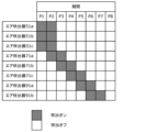
- FIG. 11 is a diagram for explaining a first example of the operation of the chip collection system according to the present embodiment.
- control unit 62 operates the plurality of air blowers 51 over a period P1 and a period P2. That is, the control unit 62 turns on the blowing of the plurality of air blowers 51 (the plurality of air blowers 51a to 51c) during the period P1 and the period P2, and moves the chips KZ in the plurality of subducts 32 to the main duct 31.
- the control unit 62 moves the chips KZ to the outlet 31D of the main duct 31 by operating the plurality of air blowers 71 in the main duct 31 in order of distance from the outlet 31D of the main duct 31.
- the control unit 62 operates the air blower 71a disposed in the main duct 31a over a period P3 and a period P4. That is, the control unit 62 turns on the blowing of the air blower 71a during the period P3 and the period P4, and moves the chips KZ in the main duct 31a to the main duct 31b.
- control unit 62 operates the air blower 71b over the period P4 and the period P5. That is, the control unit 62 turns on the air blower 71b during the period P4 and the period P5 to move the chips KZ in the main duct 31b to the main duct 31c.
- the air blower 71b operates at the same time as the air blower 71a during the overlapping period P4. In this way, the air blower 71a and the air blower 71b installed in the main ducts 31a and 31b, which are two divided areas arranged adjacent to each other, are arranged so that the operation periods for moving the chips KZ overlap. It is controlled by a control section 62.
- control unit 62 operates the air blower 71c over the period P5 and the period P6. That is, the control unit 62 turns on the blowing of the air blower 71c during the period P5 and the period P6, and moves the chips KZ in the main duct 31c to the outlet 31D of the main duct 31.
- the air blower 71c operates at the same time as the air blower 71b during the overlapping period P5. In this way, the air blower 71b and the air blower 71c installed in the main ducts 31b and 31c, which are two divided areas arranged adjacent to each other, are arranged so that the operation periods for moving the chips KZ overlap. It is controlled by a control section 62.
- control unit 62 operates the air blower 91a over the period P6 and the period P7. That is, the control unit 62 turns on the air blower 91a during the period P6 and the period P7, and moves the chips KZ in the passage section 81a to the chip rising and falling section 81b.
- the air blower 91a operates at the same time as the air blower 71c during the overlapping period P6. In this way, the air blower 71c and the air blower 91a installed in the main duct 31c and the passage section 81a, which are arranged adjacent to each other, are controlled by the control section 62 so that the operation periods for moving the chips KZ overlap. controlled.
- control unit 62 operates the air blower 91b over the period P7 and the period P8. That is, the control unit 62 turns on the blowing of the air blower 91b during the period P7 and the period P8, and moves the chips KZ in the chip rising and falling section 81b to the opening 81Kc.
- the air blower 91b operates at the same time as the air blower 91a during the overlapping period P7. In this way, the air blower 91a and the air blower 91b installed in the passage section 81a and the chip rising/falling section 81b, which are arranged adjacent to each other, are controlled by the control section so that the operation periods for moving the chips KZ overlap. 62.
- FIG. 12 is a diagram for explaining a second example of the operation of the chip collection system according to the present embodiment.
- the second example differs from the first example in that the control unit 62 controls the air blower 71a to operate simultaneously during the period P2 that overlaps with the plurality of air blowers 51. Further, as a result of advancing the timing of the operation of the air blower 71a so that it operates during the period P2 as described above, the period in which the air blowers 71a to 71c, 91a, and 91b operate extends from the period P2 to the period P7. are different. Other operations are the same as in the first example.
- FIG. 13 is a diagram for explaining a third example of the operation of the chip collection system according to the present embodiment.
- the control unit 62 controls the air blowers 91a, 91b, the plurality of air blowers 51a to 51c, and the plurality of air blowers 71a to 71c to be inoperative.
- the difference is that the operation is performed during periods P7 to P9. That is, the control unit 62 operates the air blower 91a during periods P7 to P9 when the plurality of air blowers 51a to 51c and the plurality of air blowers 71a to 71c are not operating.
- the chip collection system 1 includes a chip collection path 81, a chute 82, and a container 83.
- the chip collection path 81 collects the chips KZ of the carrier tape 18 (tape member) discharged from the tape feeder 16 included in the component mounting device 3, and drops the chips KZ that have been moved in the advancing direction.
- the chute 82 allows the chips KZ falling from the chip collection path 81 to pass through.
- the container 83 is installed below the chute 82 and stores the chips KZ that have passed through the chute 82.
- the chip collection path 81 has an air blower 91 that moves the chips KZ in the advancing direction with air.
- the chips KZ are moved by air to the chute 82, so that the chips KZ are not connected to the power source for moving the chips KZ (air blower 91 in this embodiment). It is possible to suppress the occurrence of resistance. Therefore, the chips KZ of the carrier tape 18 can be efficiently collected into the container 83 that accommodates the chips KZ.
- the chip collection path 81 includes a chip rising and falling section 81b that raises the collected chips KZ and then drops them.
- the chips KZ are lifted by air to the entrance of the chute 82 and are dropped at the exit of the chip collection path 81, so that the chips KZ serve as a power source for moving the chips KZ. This can prevent resistance to occur. Therefore, the chips KZ of the carrier tape 18 can be efficiently collected into the container 83 that accommodates the chips KZ.
- the chip collection system 1 further includes a cover member 84.
- the cover member 84 is arranged at a position extending the outlet of the chute 82 and has flexibility.
- the cover member 84 can suppress the chips KZ discharged from the outlet of the chute 82 from moving from between the chute 82 and the container 83 to the outside of the container 83.
- the cover member 84 can guide the chips KZ to the container 83.
- the chips KZ of the carrier tape 18 can be efficiently collected into the container 83 that accommodates the chips KZ.
- the cover member 84 since the cover member 84 has flexibility, even if the container 83 is moved in the horizontal direction and the container 83 interferes with the cover member 84, the cover member 84 will flex to avoid the container 83, so the container 83 will be Can be easily moved. That is, it is possible to simultaneously move the container 83 and suppress the chips that have fallen down the chute 82 from moving out of the container 83 from between the chute 82 and the container 83.
- the cover member 84 is arranged around the outlet of the chute 82. Therefore, the cover member 84 can suppress the chips KZ that have fallen down the chute 82 from moving out of the container 83 from between the chute 82 and the container 83.
- the cover member 84 has a cut extending in the vertical direction. Therefore, even if the container 83 interferes with the cover member by moving the container 83 in the horizontal direction, the cover member can avoid the container and be more easily bent, and the container can be easily moved.
- the chip collection system 1 further includes a subduct 32, a main duct 31, an air blower 51 (first air blower), and an air blower 71 (second air blower). , is provided.
- the subduct 32 receives the chips KZ discharged from the tape feeder 16.
- the main duct 31 is connected to the subduct 32 and has an opening 31K that communicates with the subduct 32.
- the air blower 51 is installed in the subduct 32 and moves the chips KZ in the subduct 32 to the main duct 31 by blowing air toward the opening 31K.
- the air blower 71 blows air toward the outlet 31D of the main duct 31, thereby moving the chips KZ that have been moved from the subduct 32 into the main duct 31 through the opening 31K to the outlet 31D of the main duct 31.
- the chip collection path 81 collects the chips KZ discharged from the outlet 31D of the main duct 31.
- the chips KZ are moved by air in the subduct 32 and the main duct 31 up to the chip collection path 81, so the chips KZ can be efficiently collected up to the chip collection path 81. Therefore, the chips KZ of the carrier tape 18 can be efficiently collected into the container 83 that accommodates the chips KZ.
- the chip collection path 81 extends in a direction intersecting the direction in which the main duct 31 extends. Therefore, the plurality of main ducts 31 can be easily connected to the chip collection path 81, and the chips KZ can be efficiently collected into the chip collection path 81.
- the chip collection system 1 includes a subduct 32, a main duct 31, an air blower 51 (first chip transport section), and a plurality of air blowers 71 (second chip transport section). , and a control section 62.
- the subduct 32 receives chips KZ of the carrier tape 18 (tape member) discharged from the tape feeder 16 included in the component mounting device 3 .
- the main duct 31 is connected to the subduct 32 and has an opening 31K that communicates with the subduct 32.
- the air blower 51 is installed in the subduct 32 and moves the chips KZ in the subduct 32 to the main duct 31.
- the plurality of air blowers 71 move the chips KZ that have been moved into the main duct 31 from the subduct 32 through the opening 31K to the outlet 31D of the main duct 31.
- the control unit 62 controls the operation of the air blower 51 and the plurality of air blowers 71.
- the control unit 62 moves the chips KZ in the subduct 32 to the main duct 31 using the air blower 51, and then moves the chips KZ to the outlet of the main duct 31 by independently controlling the plurality of air blowers 71. move it.
- the chips KZ collected from the subduct 32 to the main duct 31 by the air blower 51 are moved to the outlet of the main duct 31 by independently controlling the plurality of air blowers 71. can be efficiently moved to the outlet 31D of the main duct 31.
- the air blower 51 moves the chips KZ in the subduct 32 to the main duct 31 by blowing air toward the opening 31K.
- Each of the plurality of air blowers 51 moves the chips KZ in the main duct 31 to the outlet 31D of the main duct 31 by blowing air toward the outlet 31D of the main duct 31.
- the chips KZ are moved by air, the chips KZ can be moved without using a member for moving the chips KZ. Therefore, the internal configurations of the sub-duct 32 and the main duct 31 can be simplified, the chips KZ can be prevented from getting caught on members other than the duct, and the chips KZ can be moved efficiently.
- the main duct 31 has a plurality of divided regions arranged in series with each other.
- the plurality of air blowers 71 are respectively installed in the plurality of divided regions. According to this, the chips KZ are moved in a shared manner by the plurality of air blowers 71, so the chips KZ can be moved efficiently.
- the control unit 62 moves the chips KZ in the subduct 32 to the main duct 31 using the air blower 51, and then moves the plurality of air blowers 71 into the main duct 31.
- the chips KZ are moved to the outlet 31D of the main duct 31 by operating the chips KZ in order of distance from the outlet 31D of the main duct 31. According to this, the chips KZ are moved by relaying them within the main duct 31 using the plurality of air blowers 71, so that the chips KZ can be moved efficiently.
- the control unit 62 controls at least two air blowers installed in at least two divided regions that are arranged adjacent to each other among the plurality of air blowers 71.
- the operations of the plurality of air blowers 71 are controlled so that the periods during which the air blowers 71 (for example, air blowers 71a and 71b, or air blowers 71b and 71c) move the chips KZ overlap.
- the two air blowers 71 (for example, the air blowers 71a and 71b, or the air blowers 71b and 71c) are controlled to operate simultaneously, so that the chips KZ do not stop inside the main duct 31.
- the moving time of the chips KZ can be shortened. Therefore, the chips KZ in the main duct 31 can be efficiently relayed and moved by the plurality of air blowers 71.
- control unit 62 controls the period during which the air blower 51 and at least one air blower 71 of the plurality of air blowers 71 move the chips KZ.
- the operations of the air blower 51 and the plurality of air blowers 71 are controlled so as to overlap.
- the air blower 51 and the one air blower 71a are controlled to operate simultaneously, it is possible to move the chips KZ so that they do not stop near the joint between the subduct 32a and the main duct 31a. , the moving time of the chips KZ can be shortened. Therefore, the chips KZ near the connecting portion of the subduct 32a and the main duct 31a can be efficiently relayed and moved by the air blower 51 and one air blower 71a.
- the chip collection system 1 further includes a collection section 80.
- the collection unit 80 receives the chips KZ discharged from the outlet 31D of the main duct 31.
- the collection unit 80 includes a chip collection path 81 and an air blower 91 (fourth chip transport unit) installed in the chip collection path 81 and for moving the chips KZ to the container 83.
- the control unit 62 operates the air blower 91 during a period when the air blower 51 and the plurality of air blowers 71 are not operating. Therefore, the chips KZ collected in the collection section 80 can be moved all at once to the container 83 without any chips KZ being newly discharged to the collection section 80. Therefore, the amount of chips transferred to the container 83 can be easily controlled.
- the air blower 91 blows air toward the outlet of the chip collection path 81 to move the chips KZ in the chip collection path 81 to the container 83. According to this, since the chips KZ are moved by air, the chips KZ can be moved without using a member for moving the chips KZ. Therefore, the internal configuration of the chip collection path 81 can be simplified, the chips KZ can be prevented from being caught on members other than the chip collection path, and the chips KZ can be moved efficiently.
- the air blowers 51, 71, and 91 are supplied with air from a common supply source.
- the control unit 62 controls the operation of the air blowers 51, 71, 91 so that the number of air blowers 51, 71, 91 operating simultaneously does not exceed a predetermined number. Therefore, it is possible to prevent the pressure of the air from the supply source from decreasing below a predetermined pressure. In other words, the air pressure can be maintained above a certain level, and the chips KZ can be moved efficiently.
- FIG. 14 is a diagram showing a part of a side view of the chip collection system according to the second embodiment.
- the chip collection system 1A further collects chips KZ in the component mounting device 3 (that is, chips KZ of the cover tape of the carrier tape 18) from the component mounting device 3. It may be provided with a conveyance path 100 for carrying out.
- the conveyance path 100 is provided with a truck-side duct 101 that further communicates with the upstream side of the sub-duct 32.
- the truck side duct 101 is provided for each tape feeder 16. For this reason, the truck side duct 101 is provided for each of the plurality of subducts 32.
- the truck side duct 101 is provided with an air blower 110 that moves the cover tape chips KZ stored in the truck side duct 101 to the subduct 32.
- the air blower 110 is an example of a third chip conveying section.
- FIG. 15 is a diagram showing an example of a schematic plan view of the chip collection system in the second embodiment.
- the cover tape chips KZ discharged from the component mounting device 3a are received by the four truck-side ducts 101a and moved to the four sub-ducts 32a. Further, the chips KZ moved from the four truck-side ducts 101a by the air blower 110a and the chips KZ of the carrier tape 18 discharged from the component mounting device 3a are received in the four subducts 32a, and are transferred to the four subducts 32a. 32a is connected to the main duct 31a.
- the cover tape chips KZ discharged from the component mounting device 3b are received by the four truck-side ducts 101b and moved to the four sub-ducts 32b. Further, the chips KZ moved from the four truck-side ducts 101b by the air blower 110b and the chips KZ of the carrier tape 18 discharged from the component mounting device 3b are received in the four subducts 32b, and are transferred to the four subducts 32b. 32b is moved to the main duct 31b to which it is connected.
- the cover tape chips KZ discharged from the component mounting device 3c are received by the four truck-side ducts 101c and moved to the four sub-ducts 32c. Further, the chips KZ moved by the air blower 110c from the four truck-side ducts 101c and the chips KZ of the carrier tape 18 discharged from the component mounting device 3c are received in the four subducts 32c, and are transferred to the four subducts 32c. 32c is moved to the main duct 31c to which it is connected.
- FIG. 16 is a diagram showing an example of a control unit and a valve to be controlled by the control unit in the second embodiment.
- Each of the plurality of air blowers 110 is provided with a valve 66 (electromagnetic valve or electric valve) that opens and closes to control on/off of air blowing from the air blower 110. As shown in FIG. 16, opening and closing of the plurality of valves 66 corresponding to the plurality of air blowers 110 is controlled by the control section 62.
- a valve 66 electromagnettic valve or electric valve
- control unit 62 further controls the opening and closing of each valve 66 to control the blowing on and off of the air blower 110 corresponding to the valve 66. That is, the control unit 62 further controls the operation of the air blower 110.
- FIG. 17 is a diagram for explaining an example of the operation of the chip collection system according to the second embodiment.
- control unit 62 operates the air blower 110a over a period P1 and a period P2. That is, the control unit 62 turns on the blowing of the air blower 110a during the period P1 and the period P2, and moves the chips KZ in the truck side duct 101a to the subduct 32a.
- control unit 62 operates the air blower 51a over the period P2 and the period P3. That is, the control unit 62 turns on the blowing of the air blower 51a during the period P2 and the period P3, and moves the chips KZ in the subduct 32a to the main duct 31a.
- the control unit 62 controls the operations of the air blower 51a and the air blower 110a so that the periods of operation in which the air blower 51a and the air blower 110a move the chips KZ overlap in the period P2.
- control unit 62 moves the chips KZ to the outlet 31D of the main duct 31 by sequentially operating the air blower 71 in order of distance from the outlet 31D of the main duct 31. Specifically, the control unit 62 operates the air blower 71a disposed in the main duct 31a during periods P3 and P4, and operates the air blower 71b disposed in the main duct 31b during periods P4 and P5. The air blower 71c disposed in the main duct 31c is operated for periods P5 and P6.
- control unit 62 operates the air blower 91a over the period P7 and the period P8. That is, the control unit 62 turns on the blowing of the air blower 91a during the period P7 and the period P8, and moves the chips KZ in the passage section 81a to the chip rising and falling section 81b. Further, the control unit 62 operates the air blower 91b during the period P8 and the period P9.
- the control unit 62 operates the air blower 110b over the period P7 and the period P8. That is, the control unit 62 turns on the blowing of the air blower 110b during the period P7 and the period P8, and moves the chips KZ in the truck side duct 101b to the subduct 32b. In this way, the control unit 62 may operate the air blower 110b while the air blower 91 is operating.
- control unit 62 operates the air blower 51b over the period P8 and the period P9. That is, the control unit 62 turns on the blowing of the air blower 51b during the period P8 and the period P9, and moves the chips KZ in the subduct 32b to the main duct 31b.
- the control unit 62 controls the operations of the air blower 51b and the air blower 110b so that the periods of operation in which the air blower 51b and the air blower 110b move the chips KZ overlap in a period P8.
- control unit 62 moves the chips KZ to the outlet 31D of the main duct 31 by sequentially operating the air blower 71 in order of distance from the outlet 31D of the main duct 31.
- the air blowers 71b are sequentially operated.
- the control unit 62 operates the air blower 71b disposed in the main duct 31b for periods P9 and P10, and operates the air blower 71c disposed in the main duct 31c for periods P10 and P11. Operate over a period of time.
- control unit 62 operates the air blower 91a over the period P12 and the period P13. That is, the control unit 62 turns on the air blower 91a during the period P12 and the period P13 to move the chips KZ in the passage section 81a to the chip rising and falling section 81b. Further, the control unit 62 operates the air blower 91b during the period P13 and the period P14.
- the control unit 62 operates the air blower 110c over the period P13 and the period P14. That is, the control unit 62 turns on the blowing of the air blower 110c during the period P13 and the period P14, and moves the chips KZ in the truck side duct 101c to the subduct 32c. In this way, the control unit 62 may operate the air blower 110c while the air blower 91 is operating.
- control unit 62 operates the air blower 51c over the period P14 and the period P15. That is, the control unit 62 turns on the blowing of the air blower 51c during the period P14 and the period P15, and moves the chips KZ in the subduct 32c to the main duct 31c.
- the control unit 62 controls the operations of the air blower 51c and the air blower 110c so that the periods of operation in which the air blower 51c and the air blower 110c move the chips KZ overlap in the period P14.
- control unit 62 moves the chips KZ to the outlet 31D of the main duct 31 by sequentially operating the air blower 71 in order of distance from the outlet 31D of the main duct 31.
- the air blowers 71c are sequentially operated.
- the control unit 62 operates the air blower 71c disposed in the main duct 31c over a period P15 and a period P16.
- control unit 62 operates the air blower 91a over the period P17 and the period P18. That is, the control unit 62 turns on the blowing of the air blower 91a during the period P17 and the period P18, and moves the chips KZ in the passage section 81a to the chip rising and falling section 81b. Further, the control unit 62 operates the air blower 91b over a period P18 and a period P19.
- FIG. 18 is a cross-sectional view for explaining the configuration of the recovery section when the blower is used as an air blower.
- the recovery unit 180 includes air blowers 191a and 191b realized by blowers.
- the air blower 191a is arranged in the passage section 81a, and the air blower 191b is arranged in the chip rising and falling section 81b.
- the valve 65 and the like are not required, and the chips KZ can be conveyed with a simple configuration.
- the air blowers 51, 71, 91, and 110 are not limited to a form in which they are conveyed by air, as long as they can each convey chips.
- a device for conveying chips such as a conveyor may be provided instead of each of the air blowers 51, 71, 91, and 110.
- each component may be configured with dedicated hardware, or may be realized by executing a software program suitable for each component.
- Each component may be realized by a program execution unit such as a CPU or a processor reading and executing a software program recorded on a recording medium such as a hard disk or a semiconductor memory.
- the software that implements the control unit 62 and the like of the chip collection system 1 of the embodiment described above is a program that causes a computer to execute each step included in the flowchart shown in the figure.
- Each of the above devices is specifically a computer system composed of a microprocessor, ROM, RAM, hard disk unit, display unit, keyboard, mouse, etc.
- a computer program is stored in the RAM or hard disk unit.
- Each device achieves its function by the microprocessor operating according to the computer program.
- a computer program is configured by combining a plurality of instruction codes indicating instructions to a computer in order to achieve a predetermined function.
- a system LSI is a super-multifunctional LSI manufactured by integrating multiple components onto a single chip, and specifically, it is a computer system that includes a microprocessor, ROM, RAM, etc. .
- a computer program is stored in the RAM. The system LSI achieves its functions by the microprocessor operating according to the computer program.
- each of the above devices may be configured from an IC card or a single module that is removably attached to each device.
- the IC card or the module is a computer system composed of a microprocessor, ROM, RAM, etc.
- the IC card or the module may include the super-multifunctional LSI described above.
- the IC card or the module achieves its functions by the microprocessor operating according to a computer program. This IC card or this module may be tamper resistant.
- the present disclosure may be the method described above. Moreover, it may be a computer program that implements these methods by a computer, or it may be a digital signal composed of the computer program.
- the present disclosure also provides the computer program or the digital signal on a computer-readable recording medium, such as a flexible disk, hard disk, CD-ROM, MO, DVD, DVD-ROM, DVD-RAM, BD (Blu-ray).
- a computer-readable recording medium such as a flexible disk, hard disk, CD-ROM, MO, DVD, DVD-ROM, DVD-RAM, BD (Blu-ray).
- the information may be recorded on a registered trademark Disc), a semiconductor memory, or the like.
- the signal may be the digital signal recorded on these recording media.
- the computer program or the digital signal may be transmitted via a telecommunication line, a wireless or wired communication line, a network typified by the Internet, data broadcasting, or the like.
- the present disclosure also provides a computer system including a microprocessor and a memory, wherein the memory stores the computer program, and the microprocessor may operate according to the computer program.
- the program or the digital signal is recorded on the recording medium and transferred, or the program or the digital signal is transferred via the network or the like to be executed by another independent computer system. You can also use it as
- Chip collection system Work line 3 Component mounting device 16 Tape feeder 18 Carrier tape (tape member) 31 Main duct 31D Outlet 32 Subduct 32K Opening 41K Opening 51, 71, 91, 110 Air blower 53 Shutter 81 Chip collection path 82 Chute 83 Container 84 Cover member KZ Chips BH Parts KB Board
Landscapes
- Engineering & Computer Science (AREA)
- Manufacturing & Machinery (AREA)
- Microelectronics & Electronic Packaging (AREA)
- Supply And Installment Of Electrical Components (AREA)
Abstract
切屑回収システム(1)は、部品装着装置(3)が備えるテープフィーダ(16)から排出されたテープ部材の切屑(KZ)を収集し、進行方向に移動させた切屑(KZ)を落下させる切屑収集路(81)と、切屑収集路(81)から落下する切屑(KZ)を通過させるシュート(82)と、シュート(82)の下方に設置され、シュート(82)を通過した切屑(KZ)を収容する容器(83)と、を備え、切屑収集路(81)は、エアにより切屑(KZ)を進行方向に移動させるエア吹出器(91)を有する。
Description
本開示は、テープフィーダから排出されたテープ部材の切屑を回収する切屑回収システム及び切屑回収方法に関する。
従来、基板に部品を装着する部品装着装置において、部品供給部としてのテープフィーダから排出されたテープ部材の切屑を自動で回収する切屑回収システムが知られている(例えば下記の特許文献1)。
本開示は、テープ部材の切屑を、当該切屑を収容する容器へ効率よく集めることができる切屑回収システム及び切屑回収方法を提供する。
本開示の一態様に係る切屑回収システムは、部品装着装置が備えるテープフィーダから排出されたテープ部材の切屑を収集し、進行方向に移動させた前記切屑を落下させる切屑収集路と、前記切屑収集路から落下する前記切屑を通過させるシュートと、前記シュートの下方に設置され、前記シュートを通過した前記切屑を収容する容器と、を備え、前記切屑収集路は、エアにより前記切屑を前記進行方向に移動させるエア吹出器を有する。
本開示の一態様に係る切屑回収システムは、部品装着装置が備えるテープフィーダから排出されたテープ部材の切屑を収集し、進行方向に移動させた前記切屑を落下させる切屑収集路と、前記切屑収集路から落下する前記切屑を通過させるシュートと、前記シュートの下方に設置され、前記シュートを通過して落下した前記切屑を収容する容器と、前記シュートの出口を延長する位置に配置され、可撓性を有するカバー部材と、を備える。
本開示の切屑回収システム及び切屑回収方法によれば、テープ部材の切屑を、当該切屑を収容する容器へ効率よく集めることができる。
(本開示の基礎となった知見)
特許文献1では、テープ部材の切屑をコンベアで搬送し、収容箱(容器)へ排出することで、切屑を収容箱へ集めている。しかしながら、特許文献1では、切屑をコンベアで搬送しているため、コンベアにおいて切屑が挟まったり、引っ掛かったりすると、コンベアの動作に抵抗が生じる可能性がある。このため、コンベアのエネルギー効率の低下、または、コンベアの動力源に不具合が発生する恐れがある。
特許文献1では、テープ部材の切屑をコンベアで搬送し、収容箱(容器)へ排出することで、切屑を収容箱へ集めている。しかしながら、特許文献1では、切屑をコンベアで搬送しているため、コンベアにおいて切屑が挟まったり、引っ掛かったりすると、コンベアの動作に抵抗が生じる可能性がある。このため、コンベアのエネルギー効率の低下、または、コンベアの動力源に不具合が発生する恐れがある。
本開示の第1の態様に係る切屑回収システムは、部品装着装置が備えるテープフィーダから排出されたテープ部材の切屑を収集し、進行方向に移動させた前記切屑を落下させる切屑収集路と、前記切屑収集路から落下する前記切屑を通過させるシュートと、前記シュートの下方に設置され、前記シュートを通過した前記切屑を収容する容器と、を備え、前記切屑収集路は、エアにより前記切屑を前記進行方向に移動させるエア吹出器を有する。
これによれば、切屑収集路において、切屑がシュートまでエアにより移動されるため、切屑が当該切屑の移動のための動力源に対する抵抗の原因になることを抑制できる。よって、テープ部材の切屑を、当該切屑を収容する容器へ効率よく集めることができる。
本開示の第2の態様に係る切屑回収システムは、第1の態様に係る切屑回収システムであって、前記切屑収集路は、収集した前記切屑を上昇させてから落下させる切屑上昇落下部を有する。
これによれば、切屑収集路において、切屑がシュートの入口までエアにより上昇されて、切屑収集路の出口において落下されるため、切屑が当該切屑の移動のための動力源に対する抵抗の原因になることを抑制できる。よって、テープ部材の切屑を、当該切屑を収容する容器へ効率よく集めることができる。
本開示の第3の態様に係る切屑回収システムは、第1の態様または第2の態様に係る切屑回収システムであって、さらに、前記シュートの出口を延長する位置に配置され、可撓性を有するカバー部材を備える。
このため、カバー部材は、シュートの出口から排出される切屑が、シュート及び容器の間から容器外へ向かって移動することを抑制することができる。つまり、カバー部材は、切屑を容器へ導くことができる。テープ部材の切屑を、当該切屑を収容する容器へ効率よく集めることができる。また、カバー部材は可撓性を有するため、容器を水平方向に移動させて容器がカバー部材と干渉しても、カバー部材は容器をよけて撓むことができる。このため、容器を容易に移動させることができる。つまり、容器の移動と、シュートを落下した切屑がシュート及び容器の間から容器外へ移動することの抑制とを両立することができる。
本開示の第4の態様に係る切屑回収システムは、第3の態様に係る切屑回収システムであって、前記カバー部材は、前記シュートの出口の周縁に配置される。
このため、カバー部材は、シュートを落下した切屑がシュート及び容器の間から容器外へ移動することを抑制することができる。
本開示の第5の態様に係る切屑回収システムは、第4の態様に係る切屑回収システムであって、前記カバー部材は、鉛直方向に沿って延びる切れ目を有する。
このため、容器を水平方向移動させて容器がカバー部材と干渉しても、カバー部材が容器をよけてより撓みやすくでき、容器を容易に移動させることができる。
本開示の第6の態様に係る切屑回収システムは、第1の態様から第5の態様のいずれか1つの態様に係る切屑回収システムであって、さらに、前記テープフィーダから排出された前記切屑を受容するサブダクトと、前記サブダクトが接続されており、前記サブダクトと連通する開口部を有するメインダクトと、前記サブダクト内に設置され、前記開口部に向かってエアを吹き出すことで前記サブダクト内の前記切屑を前記メインダクトに移動させる第1エア吹出器と、前記メインダクトの出口に向かってエアを吹き出すことで、前記開口部を通じて前記サブダクトから前記メインダクト内に移動された前記切屑を、前記メインダクトの出口に移動させる第2エア吹出器と、を備え、前記切屑収集路は、前記メインダクトの出口から排出された前記切屑を収集する。
これによれば、切屑収集路までのサブダクト及びメインダクトにおいて、切屑がエアによって移動されるため、切屑を切屑収集路まで効率よく収集することができる。よって、テープ部材の切屑を、当該切屑を収容する容器へ効率よく集めることができる。
本開示の第7の態様に係る切屑回収システムは、第6の態様に係る切屑回収システムであって、前記切屑収集路は、前記メインダクトの延びる方向と交差する方向に延びる。
このため、例えば、複数本のメインダクトを切屑収集路に接続することが容易にでき、切屑収集路へ切屑を効率よく収集することができる可能性がある。
本開示の第8の態様に係る切屑回収システムは、第1の態様から第7の態様のいずれか1つの態様に係る切屑回収システムであって、前記エア吹出器は、羽根車の回転によりエアを送り出す送風機である。
このように、エア吹出器を羽根車の回転によりエアを送り出す送風機により実現することで、送風機のオンオフでエアの吹出のオンオフを切り替えることができ、簡易な構成で切屑を搬送できる。
本開示の第9の態様に係る切屑回収システムは、部品装着装置が備えるテープフィーダから排出されたテープ部材の切屑を収集し、進行方向に移動させた前記切屑を落下させる切屑収集路と、前記切屑収集路から落下する前記切屑を通過させるシュートと、前記シュートの下方に設置され、前記シュートを通過して落下した前記切屑を収容する容器と、前記シュートの出口を延長する位置に配置され、可撓性を有するカバー部材と、を備える。
このため、カバー部材は、シュートの出口から排出される切屑が、シュート及び容器の間から容器外へ向かって移動することを抑制することができる。つまり、カバー部材は、切屑を容器へ導くことができる。テープ部材の切屑を、当該切屑を収容する容器へ効率よく集めることができる。また、カバー部材は可撓性を有するため、容器を水平方向に移動させてカバー部材と干渉しても、カバー部材は容器をよけて撓むことができる。このため容器を容易に移動させることができる。つまり、容器の移動と、シュートを落下した切屑がシュート及び容器の間から容器外へ移動することの抑制とを両立することができる。
(実施の形態1)
以下、図面を参照して本発明の実施の形態を説明する。
以下、図面を参照して本発明の実施の形態を説明する。
図1は本実施の形態における切屑回収システム1が設置された作業ライン2を示している。作業ライン2は基板KBに部品を装着する複数(ここでは3台)の部品装着装置3a~3c(以下、部品装着装置3a~3cのそれぞれを部品装着装置3とも称する)が一の方向に並べられた構成を有し、隣接する部品装着装置3同士で基板KBを受け渡してその基板KBに部品を装着する。本実施の形態では、作業ライン2において基板KBを受け渡す方向(左右方向であり、部品装着装置3a~3cが並ぶ方向)をX方向、X方向と直交する水平方向(前後方向)をY方向、上下方向をZ方向とする。
図2において、部品装着装置3は基台11と基台11の上方を覆うカバー部材12を有している。基台11の上方にはカバー部材12によって覆われる作業空間13が形成されている。基台11の上面には作業空間13をX方向に延びる基板搬送部14が設置されている。基板搬送部14はY方向に並んだ一対のコンベア機構から成る。基板搬送部14は基板KBをX方向に搬送し、作業空間13内の所定の作業位置に基板KBを位置決めする。
図2において、基台11の前後それぞれの端部にはフィーダ台車15が取り付けられている。各フィーダ台車15には複数のテープフィーダ16がX方向に並べて取り付けられている(図1も参照)。各テープフィーダ16は、フィーダ台車15に保持されたテープリール17から繰り出されるテープ部材としてのキャリアテープ18を取り込んでY方向(基板搬送部14に向かう方向)に搬送し、キャリアテープ18に収納された部品BHを部品供給位置16Kに供給する。
図2において、基台11の上方には2つの装着ヘッド21がヘッド移動機構22によって移動自在に設けられている。各装着ヘッド21は下方に延びたノズル21Nを備えている。ヘッド移動機構22は例えば直交座標ロボットから成り、2つの装着ヘッド21を独立して水平面内で移動させる。各装着ヘッド21は、テープフィーダ16が部品供給位置16Kに供給する部品BHを、ノズル21Nの下端に吸着させてピックアップする(図2)。
図2において、部品装着装置3は制御装置23を備えている。制御装置23は基板搬送部14、テープフィーダ16、装着ヘッド21、ヘッド移動機構22等の各動作の制御を行う。
部品装着装置3は、部品装着作業を行うときには、先ず、基板搬送部14を作動させて上流側の装置から基板KBを受け取り、作業位置に位置決めする。部品装着装置3は基板KBを作業位置に位置決めしたら、テープフィーダ16を作動させて部品供給位置16Kに部品BHを供給させつつ、ヘッド移動機構22を作動させて、装着ヘッド21に部品移載作業を繰り返し行わせる。部品移載作業において、装着ヘッド21は、テープフィーダ16が供給する部品BHをピックアップした後、その部品BHを基板KBに装着させる。
各部品装着装置3は、装着ヘッド21による部品移載作業を繰り返し実行することによってその基板KBに装着すべき部品BHを装着したら、基板搬送部14を作動させて基板KBを下流側に搬出する。これにより3台の部品装着装置3それぞれが基板KBに部品BHを装着し、最も下流側に位置する部品装着装置3が基板KBを搬出したら、作業ライン2によるその基板KBに対する部品装着作業が終了する。
次に、切屑回収システム1について説明する。先ず、キャリアテープ18の切断について説明する。図2に示すように、各部品装着装置3が備えるフィーダ台車15は、テープカッタ24とシュータ25を有している。テープカッタ24はテープフィーダ16の下方に設けられており、テープフィーダ16が部品BHを供給し終えた後のキャリアテープ18を切断する。シュータ25は、図3(図2における領域RYの拡大図)にも示すように、テープカッタ24の下方に設けられている。シュータ25はテープカッタ24により切断されて自重で落下するキャリアテープ18の切屑KZを案内し、下端の排出開口25Kからフィーダ台車15の外部に排出させる。
このように作業ライン2を構成する各部品装着装置3からはキャリアテープ18の切屑KZが発生し、作業ライン2の全体で発生するキャリアテープ18の切屑KZは膨大な量となる。本実施の形態における切屑回収システム1は、作業ライン2から発生する多量のキャリアテープ18の切屑KZを人手によらずに自動回収することで切屑KZの廃棄処理を容易にするものである。
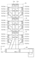
図1、図4および図5において、切屑回収システム1は、2列のメインダクト31、複数のサブダクト32および回収部80を備えている。2列のメインダクト31のそれぞれはX方向に延びた作業ライン2の下方(詳細には複数の部品装着装置3それぞれの下方)を作業ライン2の延びる方向(X方向)に延びており、上流側(一端側)と下流側(他端側)とのそれぞれに開口を有している。以下、メインダクト31におけるエアの出口を出口31Dと称する。
図4および図5において、メインダクト31は複数のダクトピース41が一の方向(部品装着装置3の並び方向であり、X方向)に直列に連結されて成る。図3に示すようにダクトピース41は断面矩形の中空形状を有し、Y方向及びZ方向のそれぞれの方向で対向する2対の壁を備えている。
図4において、メインダクト31は、主ダクトピース41Mと、距離調整用のダクトピース(調整用ダクトピース)である副ダクトピース41Sとの2種類のダクトピース41が組み合わされて成る。主ダクトピース41MはY方向に対応する2つの壁の一方に開口部41Kが形成されている(図3参照)。メインダクト31は、複数の主ダクトピース41Mを有するため、メインダクト31には、複数の開口部41Kがメインダクト31の延びる方向(X方向)に設けられている。
図1、図2および図4において、複数のサブダクト32はそれぞれフィーダ台車15の下方の床面FL上に設置されており、各サブダクト32は2列のメインダクト31の前後(Y方向)に対向する2つの壁のそれぞれに、開口部41Kを覆うようにして接続されている(図5も参照)。複数のサブダクト32は2列のメインダクト31の前側の列のメインダクト31に対向する複数のサブダクト32と、後側の列のメインダクト31に対向する複数のサブダクト32とを有する。前側の列のメインダクト31に対向する複数のサブダクト32は、前側の列のメインダクト31の前側の壁に設けられた開口部41Kと連通する状態で接続されている。また、後側の列のメインダクト31に対向する複数のサブダクト32は、後側の列のメインダクト31の後側の壁に設けられた開口部41Kと連通する状態で接続されている。
図5に示すように、部品装着装置3aから排出される切屑KZは、4つのサブダクト32aに受容されて、4つのサブダクト32aが接続されているメインダクト31aへ移動される。4つのサブダクト32aのうちの前側に配置される2つのサブダクト32aは、部品装着装置3aが備える前側のフィーダ台車15の1台分から排出される切屑KZを受容する。4つのサブダクト32aのうちの後側に配置される2つのサブダクト32aは、部品装着装置3aが備える前側のフィーダ台車15の1台分から排出される切屑KZを受容する。なお、4つのサブダクト32aは、複数のサブダクト32のうちの部品装着装置3aの下部に配置されているサブダクトである。メインダクト31aは、メインダクト31のうちの部品装着装置3aの下部に配置されているメインダクトの一部である。つまり、メインダクト31aは、メインダクト31を構成する複数の分割領域であって、互いに直列に配置されている複数の分割領域のうちの部品装着装置3aの下部の領域に対応する分割領域である。
同様に、部品装着装置3bから排出される切屑KZは、複数のサブダクト32のうちの部品装着装置3bの下部に配置されている4つのサブダクト32bに受容されて、4つのサブダクト32bが接続されているメインダクト31bへ移動される。4つのサブダクト32bのうちの前側に配置される2つのサブダクト32bは、部品装着装置3bが備える前側のフィーダ台車15の1台分から排出される切屑KZを受容する。4つのサブダクト32bのうちの後側に配置される2つのサブダクト32bは、部品装着装置3bが備える前側のフィーダ台車15の1台分から排出される切屑KZを受容する。なお、4つのサブダクト32bは、複数のサブダクト32のうちの部品装着装置3bの下部に配置されているサブダクトである。メインダクト31bは、メインダクト31のうちの部品装着装置3bの下部に配置されているメインダクトの一部である。つまり、メインダクト31bは、メインダクト31を構成する複数の分割領域であって、互いに直列に配置されている複数の分割領域のうちの部品装着装置3bの下部の領域に対応する分割領域である。
同様に、部品装着装置3cから排出される切屑KZは、複数のサブダクト32のうちの部品装着装置3cの下部に配置されている4つのサブダクト32cに受容されて、4つのサブダクト32cが接続されているメインダクト31cへ移動される。4つのサブダクト32cのうちの前側に配置される2つのサブダクト32cは、部品装着装置3cが備える前側のフィーダ台車15の1台分から排出される切屑KZを受容する。4つのサブダクト32cのうちの後側に配置される2つのサブダクト32cは、部品装着装置3cが備える前側のフィーダ台車15の1台分から排出される切屑KZを受容する。なお、4つのサブダクト32cは、複数のサブダクト32のうちの部品装着装置3cの下部に配置されているサブダクトである。メインダクト31cは、メインダクト31のうちの部品装着装置3cの下部に配置されているメインダクトの一部である。つまり、メインダクト31cは、メインダクト31を構成する複数の分割領域であって、互いに直列に配置されている複数の分割領域のうちの部品装着装置3cの下部の領域に対応する分割領域である。
また、図3に示すように、各サブダクト32の上壁には、上方(テープフィーダ16側)に開口した開口部32Kが設けられている。サブダクト32は、直上に位置する対応するシュータ25を通じて自重で落下するキャリアテープ18の切屑KZ(すなわちテープフィーダ16から排出された切屑KZ)を、開口部32Kを通じて受容する。
図3および図5において、各サブダクト32の内部にはエア吹出器51が設けられている。エア吹出器51は例えば、X方向に延びたパイプ状の部材から成り、X方向に並んだ複数のエア吹出口51Nを備えている。各エア吹出口51Nは、図3に示すように、メインダクト31の開口部41Kの方向を向けて開口している。これにより、各エア吹出器51は、メインダクト31の開口部41Kに向かってエアを吹き出すことでサブダクト32内の切屑をメインダクト31に移動させることができる。エア吹出器51は、第1切屑搬送部の一例である。
複数のサブダクト32のそれぞれには、1つずつエア吹出器51が配置されている。部品装着装置3aの下部に配置されている4つのサブダクト32aには、それぞれ、4つのエア吹出器51aが配置されている。部品装着装置3bの下部に配置されている4つのサブダクト32bには、それぞれ、4つのエア吹出器51bが配置されている。部品装着装置3cの下部に配置されている4つのサブダクト32cには、それぞれ、4つのエア吹出器51cが配置されている。
図4において、メインダクト31の前側に位置してX方向に並ぶ複数のエア吹出器51はそれぞれ、メインダクト31の前方をX方向に延びる第1エア供給路52Aと繋がっている。また、メインダクト31の後側に位置してX方向に並ぶ複数のエア吹出器51はそれぞれ、メインダクト31の後方をX方向に延びる第2エア供給路52Bと繋がっている。
図3および図5において、メインダクト31を構成する主ダクトピース41Mの壁には、開口部41Kを開閉するシャッタ53が設けられている。シャッタ53は全体として矩形平板状の部材から成り、上縁がメインダクト31に支持されている。具体的には、シャッタ53は上縁部が軸をX方向(左右方向)に向けたヒンジによってメインダクト31の上側の壁に取り付けられている。このためシャッタ53はヒンジを支点にして垂直面(YZ面)内で揺動自在になっている。
図4において、メインダクト31の前側に配置された第1エア供給路52Aとメインダクト31の後側に配置された第2エア供給路52Bとはそれぞれ、制御バルブ61に繋がっている。制御バルブ61は図示しないエア発生源(供給源)と繋がっている。
制御バルブ61の動作は制御部62(図4)によって制御され、エア発生源が発生するエアを第1エア供給路52Aまたは第2エア供給路52Bに供給する。制御バルブ61によって第1エア供給路52Aにエアが供給されると、複数のサブダクト32のうちの前側に配置される複数のサブダクト32に配置されている複数のエア吹出器51のそれぞれからエアが吹き出される。制御バルブ61によって第2エア供給路52Bにエアが供給されると、複数のサブダクト32のうちの後側に配置される複数のサブダクト32に配置されている複数のエア吹出器51のそれぞれからエアが吹き出される。
また、複数のエア吹出器51のそれぞれには、開閉することで当該エア吹出器51からエアの吹出のオンオフを制御するバルブ63(例えば電磁弁または電動弁)が設けられている。図10に示すように、複数のエア吹出器51にそれぞれ対応する複数のバルブ63の開閉は、制御部62によって制御される。
制御部62は、例えば、プログラムを実行するプロセッサ及び当該プログラムを格納しているメモリ(不揮発性メモリ)により構成されていてもよい。制御部62は、例えば、専用回路により構成されていてもよい。
エア吹出器51からエアが吹き出されていない状態では、シャッタ53は自重で垂下姿勢となっており、閉止位置に位置する。この状態からエア吹出器51からエアが吹き出されるとそのエアに押されてシャッタ53は開放位置に位置し、サブダクト32内の切屑KZは開口部41Kからメインダクト31内に移動する。エア吹出器51がエアの吹き出しを停止すると、シャッタ53は自重で垂下姿勢に戻って閉止位置に復帰する。
このように本実施の形態において、シャッタ53は、垂直面内(ここではYZ面内)で揺動自在に設けられており、エア吹出器51がエアを吹き出していない状態では開口部41Kを閉止する閉止位置に位置し、エア吹出器51がエアを吹き出している状態ではそのエア吹出器51が吹き出すエアに押されて開口部41Kを開放する開放位置に位置するようになっている。
図4および図5において、メインダクト31内には複数のエア吹出器71が設けられている。これら複数のエア吹出器71は、メインダクト31の延びる方向に直列に並んで設けられている。また、メインダクト31の複数のエア吹出器71のそれぞれの下流側には、シャッタ53と同様の構成のシャッタ72が設けられている。本実施の形態では、エア吹出器71は副ダクトピース41S内(すなわち2つの主ダクトユニットの間)に設けられている。複数のエア吹出器71は、開口部41Kを通じて各サブダクト32からメインダクト31内に移動された切屑KZをメインダクト31の出口31Dに移動させる。具体的には、複数のエア吹出器71のそれぞれは、メインダクト31の出口31Dに向かってエアを吹き出すことでメインダクト内の切屑KZをメインダクト31の出口31Dに移動させる。複数のエア吹出器71は、複数の第2切屑搬送部の一例である。
このように本実施の形態において、エア吹出器71は、主ダクトユニットごと、すなわち開口部41Kを2つずつ(一または複数ずつ)区切る位置に設けられている(図5)。つまり、複数のエア吹出器71は、それぞれ、メインダクト31の複数の分割領域に設置されており、複数の分割領域のそれぞれに1つずつエア吹出器71が配置されている。例えば、メインダクト31のうち部品装着装置3aの下部に配置されているメインダクト31aには、エア吹出器71aが配置され、メインダクト31のうち部品装着装置3bの下部に配置されているメインダクト31bには、エア吹出器71bが配置され、メインダクト31のうち部品装着装置3cの下部に配置されているメインダクト31cには、エア吹出器71cが配置されている。
図4において、複数のエア吹出器71はX方向に延びて設けられたエア供給配管71T(図4)に繋がっており、エア供給配管71Tは制御バルブ61に繋がっている。制御部62が制御バルブ61を制御し、エア供給配管71Tを通じて各エア吹出器71にエアを供給すると、そのエア吹出器71からエアが吹き出される。
また、複数のエア吹出器71のそれぞれには、開閉することで当該エア吹出器71からエアの吹出のオンオフを制御するバルブ64(電磁弁または電動弁)が設けられている。図10に示すように、複数のエア吹出器71にそれぞれ対応する複数のバルブ64の開閉は、制御部62によって制御される。
メインダクト31の出口31Dは、回収部80に接続されている。回収部80は、メインダクト31の出口31Dから排出された切屑KZを受け入れる。
図6は、本実施の形態に係る回収部の構成を説明するための斜視図である。図7は、本実施の形態に係る回収部の構成を説明するための断面図である。図7は、YZ平面で回収部のX方向の中心付近を切断したときの断面図である。
回収部80は、切屑収集路81と、シュート82と、容器83と、カバー部材84とを備える。
切屑収集路81は、メインダクト31の出口31Dから切屑KZを収集し、進行方向に移動させた切屑KZを落下させるための空間を形成している。切屑収集路81は、メインダクト31の延びる方向(X方向)と交差する方向(Y方向)に延びる。切屑収集路81は、切屑収集路81において切屑KZが移動する進行方向の上流側に配置される通路部81aと、下流側に配置される切屑上昇落下部81bとを有する。通路部81aは、メインダクト31に接続される開口部81Ka、81Kbを有し、断面矩形の中空形状を有する。通路部81aは、Y方向(水平方向)に延びている。メインダクト31は、通路部81aの壁に設けられた開口部81Ka、81Kbと連通する状態で接続されている。メインダクト31は、開口部81Ka、81Kbを覆うように通路部81aに接続されている。通路部81aの下流側に配置される切屑上昇落下部81bは、Y方向に向かうに従い斜め上方向に延びるように配置されている。切屑上昇落下部81bは、通路部81aにおいて収集された切屑KZを上昇させてから落下させる部分である。切屑上昇落下部81bは、連通した状態でシュート82と接続されている。具体的には、切屑上昇落下部81bの下流側の端部の下面に設けられた開口部81Kcは、シュート82の開口部82Kaと対向するように接続されている。
ここで、切屑収集路81には、切屑KZの進行方向に沿って、複数のエア吹出器91が配置されている。複数のエア吹出器91は、切屑収集路81内に配置され、切屑KZを容器83に移動させる。複数のエア吹出器91は、切屑収集路81の出口に向かってエアを吹き出すことで切屑収集路81内の切屑を容器83に移動させる。つまり、複数のエア吹出器91は、エアにより切屑収集路の切屑KZを進行方向に移動させる。複数のエア吹出器91のうちの通路部81aに配置されるエア吹出器91aは、通路部81aでメインダクト31から受容された切屑KZを切屑上昇落下部81bに移動させる。また、複数のエア吹出器91のうちの切屑上昇落下部81bに配置されるエア吹出器91bは、切屑上昇落下部81bに移動された切屑KZを、開口部81Kcへ移動させ、開口部81Kcからシュート82に向けて落下させる。複数のエア吹出器91は、第4切屑搬送部の一例である。
また、複数のエア吹出器91のそれぞれには、開閉することで当該エア吹出器91からエアの吹出のオンオフを制御するバルブ65(電磁弁または電動弁)が設けられている。図10に示すように、複数のエア吹出器91にそれぞれ対応する複数のバルブ65の開閉は、制御部62によって制御される。
シュート82は、切屑収集路81から落下する(つまりZ方向に移動する)切屑KZを通過させる断面矩形状の筒状部材である。シュート82は、Z方向に沿って配置される。つまり、シュート82は、Z方向に貫通している空間を有する。
容器83は、シュート82の下方に配置され、シュート82を通過した切屑KZを収容する。例えば、容器83は、上側が開放されている箱状の部材である。容器83には、容器83が床面FL上を移動することが容易にできるように車輪83aが設けられていてもよい。
カバー部材84は、シュート82の出口を延長する位置に配置され、可撓性を有する。カバー部材84は、例えば、シート状の部材である。カバー部材84は、図8に示すように、シュート82の出口の周縁に配置される。カバー部材84は、例えば、断面矩形のシュート82の出口の4辺の全てに配置される。また、カバー部材84は、Z方向(鉛直方向)に延びる切れ目84aを有する。シュート82の出口の1辺毎に配置される4枚のシート状の部材であってもよい。なお、図8は、カバー部材の構成を説明するための斜視図である。
図9は、カバー部材の機能について説明するための図である。
図9の(a)に示すように、切屑KZを収集しているときには、容器83は、シュート82の直下に配置されている。この時、カバー部材84は、その下端が容器83の内方に配置されている。このため、シュート82を落下した切屑KZがシュート82と容器83との間から容器83外へ移動することを抑制することができる。
また、切屑KZの収集が停止されたときに、容器83に貯まった切屑KZを回収するために床面FL上で容器83を移動させる。このとき、カバー部材84は可撓性を有するため、図9の(b)に示すように、容器83の移動を妨げることが少ない。また、図9の(c)に示すように、容器83をシュート82の元の位置に戻す際も同様である。つまり、容器83の移動と、シュート82を落下した切屑KZがシュート82及び容器83の間から容器83外へ移動することの抑制とを両立させることができる。
図10は、本実施の形態において、制御部とその制御対象となるバルブとの一例を示す図である。
上述したように、制御部62は、各バルブ63の開閉を制御することで当該バルブ63に対応するエア吹出器51の吹出のオンオフを制御する。また、制御部62は、各バルブ64の開閉を制御することで当該バルブ64に対応するエア吹出器71の吹出のオンオフを制御する。つまり、制御部62は、エア吹出器51及びエア吹出器71の動作を制御する。また、制御部62は、各バルブ65の開閉を制御することで当該バルブ65に対応するエア吹出器91の吹出のオンオフを制御してもよい。つまり、制御部62は、さらに、エア吹出器91の動作を制御する。
制御部62は、複数のエア吹出器51によってサブダクト32内の切屑KZをメインダクト31に移動させた後、複数のエア吹出器71をそれぞれ独立して制御することで切屑KZをメインダクト31の出口31Dに移動させる。具体的には、複数のエア吹出器71のそれぞれによって単位時間当たりに移動される切屑KZの量が所定量を超えないように、複数のエア吹出器71の動作を独立して制御する。これにより、切屑KZがメインダクト31内で移動しにくくなることを抑制し、効率よく切屑KZを移動させることができる。
図11は、本実施の形態に係る切屑回収システムの動作の第1の例を説明するための図である。
まず、制御部62は、複数のエア吹出器51を期間P1及び期間P2にわたって動作させる。つまり、制御部62は、期間P1及び期間P2において複数のエア吹出器51(複数のエア吹出器51a~51c)の吹出をオンにして、複数のサブダクト32内の切屑KZをメインダクト31へ移動させる。
次に、制御部62は、メインダクト31内の複数のエア吹出器71をメインダクト31の出口31Dから遠い順に順次動作させることで切屑KZをメインダクト31の出口31Dに移動させる。具体的には、制御部62は、メインダクト31aに配置されているエア吹出器71aを期間P3及び期間P4にわたって動作させる。つまり、制御部62は、期間P3及び期間P4においてエア吹出器71aの吹出をオンにして、メインダクト31a内の切屑KZをメインダクト31bへ移動させる。
また、制御部62は、エア吹出器71bを期間P4及び期間P5にわたって動作させる。つまり、制御部62は、期間P4及び期間P5においてエア吹出器71bの吹出をオンにして、メインダクト31b内の切屑KZをメインダクト31cへ移動させる。エア吹出器71bは、エア吹出器71aと重複する期間P4において同時に動作する。このように、互いに隣接して配置される2つの分割領域であるメインダクト31a、31bに設置されるエア吹出器71a及びエア吹出器71bは、切屑KZを移動させる動作の期間が重複するように制御部62によって制御される。
また、制御部62は、エア吹出器71cを期間P5及び期間P6にわたって動作させる。つまり、制御部62は、期間P5及び期間P6においてエア吹出器71cの吹出をオンにして、メインダクト31c内の切屑KZをメインダクト31の出口31Dへ移動させる。エア吹出器71cは、エア吹出器71bと重複する期間P5において同時に動作する。このように、互いに隣接して配置される2つの分割領域であるメインダクト31b、31cに設置されるエア吹出器71b及びエア吹出器71cは、切屑KZを移動させる動作の期間が重複するように制御部62によって制御される。
また、制御部62は、エア吹出器91aを期間P6及び期間P7にわたって動作させる。つまり、制御部62は、期間P6及び期間P7においてエア吹出器91aの吹出をオンにして、通路部81a内の切屑KZを切屑上昇落下部81bへ移動させる。エア吹出器91aは、エア吹出器71cと重複する期間P6において同時に動作する。このように、互いに隣接して配置されるメインダクト31c及び通路部81aに設置されるエア吹出器71c及びエア吹出器91aは、切屑KZを移動させる動作の期間が重複するように制御部62によって制御される。
また、制御部62は、エア吹出器91bを期間P7及び期間P8にわたって動作させる。つまり、制御部62は、期間P7及び期間P8においてエア吹出器91bの吹出をオンにして、切屑上昇落下部81b内の切屑KZを開口部81Kcへ移動させる。エア吹出器91bは、エア吹出器91aと重複する期間P7において同時に動作する。このように、互いに隣接して配置される通路部81a及び切屑上昇落下部81bに設置されるエア吹出器91a及びエア吹出器91bは、切屑KZを移動させる動作の期間が重複するように制御部62によって制御される。
図12は、本実施の形態に係る切屑回収システムの動作の第2の例を説明するための図である。
第1の例と比較して、第2の例では、制御部62は、エア吹出器71aを、複数のエア吹出器51と重複する期間P2において同時に動作するように制御する点が異なる。また、上記のようにエア吹出器71aを期間P2で動作するように動作のタイミングを早めた結果、エア吹出器71a~71c、91a、91bが動作する期間が期間P2~期間P7にわたって動作する点が異なる。他の動作は、第1の例と同じである。
図13は、本実施の形態に係る切屑回収システムの動作の第3の例を説明するための図である。
第1の例と比較して、第3の例では、制御部62は、エア吹出器91a、91bを、複数のエア吹出器51a~51c及び複数のエア吹出器71a~71cが動作していない期間P7~P9に動作させる点が異なる。つまり、制御部62は、エア吹出器91aを複数のエア吹出器51a~51c及び複数のエア吹出器71a~71cが動作していない期間P7~P9に動作させる。
本実施の形態に係る切屑回収システム1は、切屑収集路81と、シュート82と、容器83とを備える。切屑収集路81は、部品装着装置3が備えるテープフィーダ16から排出されたキャリアテープ18(テープ部材)の切屑KZを収集し、進行方向に移動させた切屑KZを落下させる。シュート82は、切屑収集路81から落下する切屑KZを通過させる。容器83は、シュート82の下方に設置され、シュート82を通過した切屑KZを収容する。切屑収集路81は、エアにより切屑KZを進行方向に移動させるエア吹出器91を有する。
これによれば、切屑収集路81において、切屑KZがシュート82までエアにより移動されるため、切屑KZが当該切屑KZの移動のための動力源(本実施の形態ではエア吹出器91)に対して抵抗になることを抑制できる。よって、キャリアテープ18の切屑KZを、当該切屑KZを収容する容器83へ効率よく集めることができる。
また、本実施の形態に係る切屑回収システム1において、切屑収集路81は、収集した切屑KZを上昇させてから落下させる切屑上昇落下部81bを有する。
これによれば、切屑収集路81において、切屑KZがシュート82の入口までエアにより上昇されて、切屑収集路81の出口において落下されるため、切屑KZが当該切屑KZの移動のための動力源に対して抵抗になることを抑制できる。よって、キャリアテープ18の切屑KZを、当該切屑KZを収容する容器83へ効率よく集めることができる。
また、本実施の形態に係る切屑回収システム1は、さらに、カバー部材84を有する。カバー部材84は、シュート82の出口を延長する位置に配置され、可撓性を有する。
このため、カバー部材84は、シュート82の出口から排出される切屑KZが、シュート82及び容器83の間から容器83外へ向かって移動することを抑制することができる。つまり、カバー部材84は、切屑KZを容器83へ導くことができる。キャリアテープ18の切屑KZを、当該切屑KZを収容する容器83へ効率よく集めることができる。また、カバー部材84は可撓性を有するため、容器83を水平方向に移動させて容器83がカバー部材84と干渉しても、カバー部材84は容器83をよけて撓むため容器83を容易に移動させることができる。つまり、容器83の移動と、シュート82を落下した切屑がシュート82及び容器83の間から容器83外へ移動することの抑制とを両立することができる。
また、本実施の形態に係る切屑回収システム1において、カバー部材84は、シュート82の出口の周縁に配置される。このため、カバー部材84は、シュート82を落下した切屑KZがシュート82及び容器83の間から容器83外へ移動することを抑制することができる。
また、本実施の形態に係る切屑回収システム1において、カバー部材84は、鉛直方向に沿って延びる切れ目を有する。このため、容器83を水平方向に移動させて容器83がカバー部材と干渉しても、カバー部材が容器をよけてより撓みやすくでき、容器を容易に移動させることができる。
また、本実施の形態に係る切屑回収システム1は、さらに、サブダクト32と、メインダクト31と、エア吹出器51(第1エア吹出器)と、エア吹出器71(第2エア吹出器)と、を備える。サブダクト32は、テープフィーダ16から排出された切屑KZを受容する。メインダクト31は、サブダクト32が接続されており、サブダクト32と連通する開口部31Kを有する。エア吹出器51は、サブダクト32内に設置され、開口部31Kに向かってエアを吹き出すことでサブダクト32内の切屑KZをメインダクト31に移動させる。エア吹出器71は、メインダクト31の出口31Dに向かってエアを吹き出すことで、開口部31Kを通じてサブダクト32からメインダクト31内に移動された切屑KZを、メインダクト31の出口31Dに移動させる。切屑収集路81は、メインダクト31の出口31Dから排出された切屑KZを収集する。
これによれば、切屑収集路81までのサブダクト32及びメインダクト31において、切屑KZがエアによって移動されるため、切屑KZを切屑収集路81まで効率よく収集することができる。よって、キャリアテープ18の切屑KZを、当該切屑KZを収容する容器83へ効率よく集めることができる。
また、本実施の形態に係る切屑回収システム1において、切屑収集路81は、メインダクト31の延びる方向と交差する方向に延びる。このため、複数本のメインダクト31を切屑収集路81に接続することが容易にでき、切屑収集路81へ切屑KZを効率よく収集することができる。
また、本実施の形態に係る切屑回収システム1は、サブダクト32と、メインダクト31と、エア吹出器51(第1切屑搬送部)と、複数のエア吹出器71(第2切屑搬送部)と、制御部62とを備える。サブダクト32は、部品装着装置3が備えるテープフィーダ16から排出されたキャリアテープ18(テープ部材)の切屑KZを受容する。メインダクト31は、サブダクト32が接続されており、サブダクト32と連通する開口部31Kを有する。エア吹出器51は、サブダクト32内に設置され、サブダクト32内の切屑KZをメインダクト31に移動させる。複数のエア吹出器71は、開口部31Kを通じてサブダクト32からメインダクト31内に移動された切屑KZをメインダクト31の出口31Dに移動させる。制御部62は、エア吹出器51及び複数のエア吹出器71の動作を制御する。制御部62は、エア吹出器51によってサブダクト32内の切屑KZをメインダクト31に移動させた後、複数のエア吹出器71をそれぞれ独立して制御することで切屑KZをメインダクト31の出口に移動させる。
これによれば、エア吹出器51によってサブダクト32からメインダクト31へ集めた切屑KZを、複数のエア吹出器71をそれぞれ独立して制御することでメインダクト31の出口に移動させるため、切屑KZをメインダクト31の出口31Dまで効率よく移動させることができる。
また、本実施の形態に係る切屑回収システム1において、エア吹出器51は、開口部31Kに向かってエアを吹き出すことでサブダクト32内の切屑KZをメインダクト31に移動させる。複数のエア吹出器51のそれぞれは、メインダクト31の出口31Dに向かってエアを吹き出すことでメインダクト31内の切屑KZをメインダクト31の出口31Dに移動させる。
これによれば、切屑KZをエアによって移動させるため、切屑KZを移動させるための部材を利用することなく切屑KZを移動させることができる。よって、サブダクト32及びメインダクト31の内部の構成を単純化することができ、切屑KZがダクト以外の部材に引っ掛かることを抑制でき、切屑KZを効率よく移動させることができる。
また、本実施の形態に係る切屑回収システム1において、メインダクト31は、互いに直列に配置されている複数の分割領域を有する。複数のエア吹出器71は、それぞれ、複数の分割領域に設置される。これによれば、切屑KZを複数のエア吹出器71で分担して移動させるため、切屑KZを効率よく移動させることができる。
また、本実施の形態に係る切屑回収システム1において、制御部62は、エア吹出器51によってサブダクト32内の切屑KZをメインダクト31に移動させた後、複数のエア吹出器71をメインダクト31の出口31Dから遠い順に順次動作させることで切屑KZをメインダクト31の出口31Dに移動させる。これによれば、切屑KZを複数のエア吹出器71でメインダクト31内をリレーして切屑KZを移動させるため、切屑KZを効率よく移動させることができる。
また、本実施の形態に係る切屑回収システム1において、制御部62は、複数のエア吹出器71のうち、互いに隣接して配置される少なくとも2つの分割領域に設置される少なくとも2つのエア吹出器71(例えば、エア吹出器71a及び71b、または、エア吹出器71b及び71c)が切屑KZを移動させる動作の期間が重複するように複数のエア吹出器71の動作を制御する。
これによれば、2つのエア吹出器71(例えば、エア吹出器71a及び71b、または、エア吹出器71b及び71c)が同時に動作するように制御するため、切屑KZがメインダクト31内で止まらないように移動させることができ、切屑KZの移動時間を短縮できる。よって、メインダクト31内における切屑KZを複数のエア吹出器71で効率よくリレーして移動させることができる。
また、本実施の形態に係る切屑回収システム1において、制御部62は、エア吹出器51と、複数のエア吹出器71の少なくとも1つのエア吹出器71とが切屑KZを移動させる動作の期間が重複するようにエア吹出器51及び複数のエア吹出器71の動作を制御する。
これによれば、エア吹出器51と1つのエア吹出器71aとが同時に動作するように制御するため、切屑KZがサブダクト32a及びメインダクト31aの連結部付近において止まらないように移動させることができ、切屑KZの移動時間を短縮できる。よって、サブダクト32a及びメインダクト31aの連結部付近における切屑KZをエア吹出器51及び1つのエア吹出器71aで効率よくリレーして移動させることができる。
また、本実施の形態に係る切屑回収システム1は、さらに、回収部80を備える。回収部80は、メインダクト31の出口31Dから排出された切屑KZを受け入れる。回収部80は、切屑収集路81と、切屑収集路81内に設置され、切屑KZを容器83に移動させるエア吹出器91(第4切屑搬送部)と、を有する。制御部62は、エア吹出器51と複数のエア吹出器71とが動作していない期間にエア吹出器91を動作させる。このため、回収部80へ新たに排出される切屑KZがない状態で、回収部80に集めた切屑KZを容器83へまとめて移動させることができる。よって、容器83へ移動させる切屑の量の制御を容易にできる。
また、本実施の形態に係る切屑回収システム1において、エア吹出器91は、切屑収集路81の出口に向かってエアを吹き出すことで切屑収集路81内の切屑KZを容器83に移動させる。これによれば、切屑KZをエアによって移動させるため、切屑KZを移動させるための部材を利用することなく切屑KZを移動させることができる。よって、切屑収集路81の内部の構成を単純化することができ、切屑KZが切屑収集路以外の部材に引っ掛かることを抑制でき、切屑KZを効率よく移動させることができる。
また、本実施の形態に係る切屑回収システム1において、エア吹出器51、71、91は、共通する供給源からエアの供給を受けている。制御部62は、同時に動作するエア吹出器51、71、91の数が所定の数を超えないようにエア吹出器51、71、91の動作を制御する。このため、供給源からのエアの圧力を所定の圧力よりも低下することを抑制することができる。つまり、エアの圧力を一定以上に保つことができ、切屑KZを効率よく移動させることができる。
(実施の形態2)
図14は、実施の形態2における切屑回収システムの側面図の一部を示す図である。
図14は、実施の形態2における切屑回収システムの側面図の一部を示す図である。
実施の形態2に係る切屑回収システム1Aは、図14に示すように、さらに、部品装着装置3から部品装着装置3内の切屑KZ(つまり、キャリアテープ18のカバーテープの切屑KZ)をさらに回収するための搬送路100を備えていてもよい。搬送路100には、サブダクト32の上流側にさらに連通する台車側ダクト101が設けられている。台車側ダクト101は、1つのテープフィーダ16毎に設けられる。このため、台車側ダクト101は、複数のサブダクト32のそれぞれに対して設けられる。台車側ダクト101には、台車側ダクト101に収容されたカバーテープの切屑KZを、サブダクト32に移動させるエア吹出器110が設けられている。エア吹出器110は、第3切屑搬送部の一例である。
図15は、実施の形態2における切屑回収システムの模式的平面図の一例を示す図である。
図15に示すように、部品装着装置3aから排出されるカバーテープの切屑KZは、4つの台車側ダクト101aに受容されて、4つのサブダクト32aへ移動される。また、4つの台車側ダクト101aからエア吹出器110aによって移動された切屑KZ、及び、部品装着装置3aから排出されるキャリアテープ18の切屑KZは、4つのサブダクト32aに受容されて、4つのサブダクト32aが接続されているメインダクト31aへ移動される。
同様に、部品装着装置3bから排出されるカバーテープの切屑KZは、4つの台車側ダクト101bに受容されて、4つのサブダクト32bへ移動される。また、4つの台車側ダクト101bからエア吹出器110bによって移動された切屑KZ、及び、部品装着装置3bから排出されるキャリアテープ18の切屑KZは、4つのサブダクト32bに受容されて、4つのサブダクト32bが接続されているメインダクト31bへ移動される。
同様に、部品装着装置3cから排出されるカバーテープの切屑KZは、4つの台車側ダクト101cに受容されて、4つのサブダクト32cへ移動される。また、4つの台車側ダクト101cからエア吹出器110cによって移動された切屑KZ、及び、部品装着装置3cから排出されるキャリアテープ18の切屑KZは、4つのサブダクト32cに受容されて、4つのサブダクト32cが接続されているメインダクト31cへ移動される。
図16は、実施の形態2において、制御部とその制御対象となるバルブとの一例を示す図である。
複数のエア吹出器110のそれぞれには、開閉することで当該エア吹出器110からエアの吹出のオンオフを制御するバルブ66(電磁弁または電動弁)が設けられている。図16に示すように、複数のエア吹出器110にそれぞれ対応する複数のバルブ66の開閉は、制御部62によって制御される。
上述したように、制御部62は、さらに、各バルブ66の開閉を制御することで当該バルブ66に対応するエア吹出器110の吹出のオンオフを制御する。つまり、制御部62は、さらに、エア吹出器110の動作を制御する。
図17は、実施の形態2に係る切屑回収システムの動作の一例を説明するための図である。
まず、制御部62は、エア吹出器110aを期間P1及び期間P2にわたって動作させる。つまり、制御部62は、期間P1及び期間P2においてエア吹出器110aの吹出をオンにして、台車側ダクト101a内の切屑KZをサブダクト32aへ移動させる。
また、制御部62は、エア吹出器51aを期間P2及び期間P3にわたって動作させる。つまり、制御部62は、期間P2及び期間P3においてエア吹出器51aの吹出をオンにして、サブダクト32a内の切屑KZをメインダクト31aへ移動させる。制御部62は、エア吹出器51aと、エア吹出器110aとが切屑KZを移動させる動作の期間が期間P2で重複するようにエア吹出器51a及びエア吹出器110aの動作を制御する。
また、制御部62は、エア吹出器71をメインダクト31の出口31Dから遠い順に順次動作させることで切屑KZをメインダクト31の出口31Dに移動させる。具体的には、制御部62は、メインダクト31aに配置されているエア吹出器71aを期間P3及び期間P4にわたって動作させ、メインダクト31bに配置されているエア吹出器71bを期間P4及び期間P5にわたって動作させ、メインダクト31cに配置されているエア吹出器71cを期間P5及び期間P6にわたって動作させる。
また、制御部62は、エア吹出器91aを期間P7及び期間P8にわたって動作させる。つまり、制御部62は、期間P7及び期間P8においてエア吹出器91aの吹出をオンにして、通路部81a内の切屑KZを切屑上昇落下部81bへ移動させる。また、制御部62は、エア吹出器91bを期間P8及び期間P9にわたって動作させる。
このとき、制御部62は、エア吹出器110bを期間P7及び期間P8にわたって動作させる。つまり、制御部62は、期間P7及び期間P8においてエア吹出器110bの吹出をオンにして、台車側ダクト101b内の切屑KZをサブダクト32bへ移動させる。このように、制御部62は、エア吹出器91が動作している期間中に、エア吹出器110bを動作させてもよい。
また、制御部62は、エア吹出器51bを期間P8及び期間P9にわたって動作させる。つまり、制御部62は、期間P8及び期間P9においてエア吹出器51bの吹出をオンにして、サブダクト32b内の切屑KZをメインダクト31bへ移動させる。制御部62は、エア吹出器51bと、エア吹出器110bとが切屑KZを移動させる動作の期間が期間P8で重複するようにエア吹出器51b及びエア吹出器110bの動作を制御する。
また、制御部62は、エア吹出器71をメインダクト31の出口31Dから遠い順に順次動作させることで切屑KZをメインダクト31の出口31Dに移動させる。この場合、期間P1~P8において、部品装着装置3aから発生した切屑KZを搬送したため、エア吹出器71bから順に順次動作させる。具体的には、制御部62は、メインダクト31bに配置されているエア吹出器71bを期間P9及び期間P10にわたって動作させ、メインダクト31cに配置されているエア吹出器71cを期間P10及び期間P11にわたって動作させる。
また、制御部62は、エア吹出器91aを期間P12及び期間P13にわたって動作させる。つまり、制御部62は、期間P12及び期間P13においてエア吹出器91aの吹出をオンにして、通路部81a内の切屑KZを切屑上昇落下部81bへ移動させる。また、制御部62は、エア吹出器91bを期間P13及び期間P14にわたって動作させる。
このとき、制御部62は、エア吹出器110cを期間P13及び期間P14にわたって動作させる。つまり、制御部62は、期間P13及び期間P14においてエア吹出器110cの吹出をオンにして、台車側ダクト101c内の切屑KZをサブダクト32cへ移動させる。このように、制御部62は、エア吹出器91が動作している期間中に、エア吹出器110cを動作させてもよい。
また、制御部62は、エア吹出器51cを期間P14及び期間P15にわたって動作させる。つまり、制御部62は、期間P14及び期間P15においてエア吹出器51cの吹出をオンにして、サブダクト32c内の切屑KZをメインダクト31cへ移動させる。制御部62は、エア吹出器51cと、エア吹出器110cとが切屑KZを移動させる動作の期間が期間P14で重複するようにエア吹出器51c及びエア吹出器110cの動作を制御する。
また、制御部62は、エア吹出器71をメインダクト31の出口31Dから遠い順に順次動作させることで切屑KZをメインダクト31の出口31Dに移動させる。この場合、期間P7~P14において、部品装着装置3bから発生した切屑KZを搬送したため、エア吹出器71cから順に順次動作させる。具体的には、制御部62は、メインダクト31cに配置されているエア吹出器71cを期間P15及び期間P16にわたって動作させる。
また、制御部62は、エア吹出器91aを期間P17及び期間P18にわたって動作させる。つまり、制御部62は、期間P17及び期間P18においてエア吹出器91aの吹出をオンにして、通路部81a内の切屑KZを切屑上昇落下部81bへ移動させる。また、制御部62は、エア吹出器91bを期間P18及び期間P19にわたって動作させる。
なお、エア吹出器91の他の例として、羽根車(またはファン)の回転によりエアを送り出す送風機を用いてもよい。図18は、送風機をエア吹出器として用いる場合の回収部の構成を説明するための断面図である。図18に示すように、回収部180は、送風機により実現されるエア吹出器191a、191bを備える。エア吹出器191aは、通路部81aに配置され、エア吹出器191bは、切屑上昇落下部81bに配置される。このように、エア吹出器191a、191bを羽根車の回転によりエアを送り出す送風機により実現することでバルブ65等が不要となり、簡易な構成で切屑KZを搬送できる。
また、上記実施の形態では、エア吹出器51、71、91、110は、それぞれ、切屑を搬送できればよく、エアにより搬送する形態に限らない。例えば、エア吹出器51、71、91、110のそれぞれの代わりにコンベアなどの切屑を搬送する装置が設けられていてもよい。
なお、上記実施の形態において、各構成要素は、専用のハードウェアで構成されるか、各構成要素に適したソフトウェアプログラムを実行することによって実現されてもよい。各構成要素は、CPUまたはプロセッサなどのプログラム実行部が、ハードディスクまたは半導体メモリなどの記録媒体に記録されたソフトウェアプログラムを読み出して実行することによって実現されてもよい。ここで、上記実施の形態の切屑回収システム1の制御部62などを実現するソフトウェアは、図に示すフローチャートに含まれる各ステップをコンピュータに実行させるプログラムである。
なお、以下のような場合も本開示に含まれる。
(1)上記の各装置は、具体的には、マイクロプロセッサ、ROM、RAM、ハードディスクユニット、ディスプレイユニット、キーボード、マウスなどから構成されるコンピュータシステムである。前記RAMまたはハードディスクユニットには、コンピュータプログラムが記憶されている。前記マイクロプロセッサが、前記コンピュータプログラムにしたがって動作することにより、各装置は、その機能を達成する。ここでコンピュータプログラムは、所定の機能を達成するために、コンピュータに対する指令を示す命令コードが複数個組み合わされて構成されたものである。
(2)上記の各装置を構成する構成要素の一部または全部は、1個のシステムLSI(Large Scale Integration:大規模集積回路)から構成されているとしてもよい。システムLSIは、複数の構成部を1個のチップ上に集積して製造された超多機能LSIであり、具体的には、マイクロプロセッサ、ROM、RAMなどを含んで構成されるコンピュータシステムである。前記RAMには、コンピュータプログラムが記憶されている。前記マイクロプロセッサが、前記コンピュータプログラムにしたがって動作することにより、システムLSIは、その機能を達成する。
(3)上記の各装置を構成する構成要素の一部または全部は、各装置に脱着可能なICカードまたは単体のモジュールから構成されているとしてもよい。前記ICカードまたは前記モジュールは、マイクロプロセッサ、ROM、RAMなどから構成されるコンピュータシステムである。前記ICカードまたは前記モジュールは、上記の超多機能LSIを含むとしてもよい。マイクロプロセッサが、コンピュータプログラムにしたがって動作することにより、前記ICカードまたは前記モジュールは、その機能を達成する。このICカードまたはこのモジュールは、耐タンパ性を有するとしてもよい。
(4)本開示は、上記に示す方法であるとしてもよい。また、これらの方法をコンピュータにより実現するコンピュータプログラムであるとしてもよいし、前記コンピュータプログラムからなるデジタル信号であるとしてもよい。
また、本開示は、前記コンピュータプログラムまたは前記デジタル信号をコンピュータ読み取り可能な記録媒体、例えば、フレキシブルディスク、ハードディスク、CD-ROM、MO、DVD、DVD-ROM、DVD-RAM、BD(Blu-ray(登録商標) Disc)、半導体メモリなどに記録したものとしてもよい。また、これらの記録媒体に記録されている前記デジタル信号であるとしてもよい。
また、本開示は、前記コンピュータプログラムまたは前記デジタル信号を、電気通信回線、無線または有線通信回線、インターネットを代表とするネットワーク、データ放送等を経由して伝送するものとしてもよい。
また、本開示は、マイクロプロセッサとメモリを備えたコンピュータシステムであって、前記メモリは、上記コンピュータプログラムを記憶しており、前記マイクロプロセッサは、前記コンピュータプログラムにしたがって動作するとしてもよい。
また、前記プログラムまたは前記デジタル信号を前記記録媒体に記録して移送することにより、または前記プログラムまたは前記デジタル信号を前記ネットワーク等を経由して移送することにより、独立した他のコンピュータシステムにより実施するとしてもよい。
(5)上記実施の形態及び上記変形例をそれぞれ組み合わせるとしてもよい。
メインダクト内のテープ部材の切屑をメインダクトの出口まで効率よく移動させることができる切屑回収システムおよび切屑回収方法を提供する。
1 切屑回収システム
2 作業ライン
3 部品装着装置
16 テープフィーダ
18 キャリアテープ(テープ部材)
31 メインダクト
31D 出口
32 サブダクト
32K 開口部
41K 開口部
51、71、91、110 エア吹出器
53 シャッタ
81 切屑収集路
82 シュート
83 容器
84 カバー部材
KZ 切屑
BH 部品
KB 基板
2 作業ライン
3 部品装着装置
16 テープフィーダ
18 キャリアテープ(テープ部材)
31 メインダクト
31D 出口
32 サブダクト
32K 開口部
41K 開口部
51、71、91、110 エア吹出器
53 シャッタ
81 切屑収集路
82 シュート
83 容器
84 カバー部材
KZ 切屑
BH 部品
KB 基板
Claims (9)
- 部品装着装置が備えるテープフィーダから排出されたテープ部材の切屑を収集し、進行方向に移動させた前記切屑を落下させる切屑収集路と、
前記切屑収集路から落下する前記切屑を通過させるシュートと、
前記シュートの下方に設置され、前記シュートを通過した前記切屑を収容する容器と、を備え、
前記切屑収集路は、エアにより前記切屑を前記進行方向に移動させるエア吹出器を有する
切屑回収システム。 - 前記切屑収集路は、収集した前記切屑を上昇させてから落下させる切屑上昇落下部を有する
請求項1に記載の切屑回収システム。 - さらに、
前記シュートの出口を延長する位置に配置され、可撓性を有するカバー部材を備える
請求項1または2に記載の切屑回収システム。 - 前記カバー部材は、前記シュートの出口の周縁に配置される
請求項3に記載の切屑回収システム。 - 前記カバー部材は、鉛直方向に沿って延びる切れ目を有する
請求項4に記載の切屑回収システム。 - さらに、
前記テープフィーダから排出された前記切屑を受容するサブダクトと、
前記サブダクトが接続されており、前記サブダクトと連通する開口部を有するメインダクトと、
前記サブダクト内に設置され、前記開口部に向かってエアを吹き出すことで前記サブダクト内の前記切屑を前記メインダクトに移動させる第1エア吹出器と、
前記メインダクトの出口に向かってエアを吹き出すことで、前記開口部を通じて前記サブダクトから前記メインダクト内に移動された前記切屑を、前記メインダクトの出口に移動させる第2エア吹出器と、を備え、
前記切屑収集路は、前記メインダクトの出口から排出された前記切屑を収集する
請求項1または2に記載の切屑回収システム。 - 前記切屑収集路は、前記メインダクトの延びる方向と交差する方向に延びる
請求項6に記載の切屑回収システム。 - 前記エア吹出器は、羽根車の回転によりエアを送り出す送風機である
請求項1または2に記載の切屑回収システム。 - 部品装着装置が備えるテープフィーダから排出されたテープ部材の切屑を収集し、進行方向に移動させた前記切屑を落下させる切屑収集路と、
前記切屑収集路から落下する前記切屑を通過させるシュートと、
前記シュートの下方に設置され、前記シュートを通過して落下した前記切屑を収容する容器と、
前記シュートの出口を延長する位置に配置され、可撓性を有するカバー部材と、を備える
切屑回収システム。
Applications Claiming Priority (2)
| Application Number | Priority Date | Filing Date | Title |
|---|---|---|---|
| JP2022148414 | 2022-09-16 | ||
| JP2022-148414 | 2022-09-16 |
Publications (1)
| Publication Number | Publication Date |
|---|---|
| WO2024057624A1 true WO2024057624A1 (ja) | 2024-03-21 |
Family
ID=90274454
Family Applications (1)
| Application Number | Title | Priority Date | Filing Date |
|---|---|---|---|
| PCT/JP2023/019084 WO2024057624A1 (ja) | 2022-09-16 | 2023-05-23 | 切屑回収システム |
Country Status (1)
| Country | Link |
|---|---|
| WO (1) | WO2024057624A1 (ja) |
Citations (7)
| Publication number | Priority date | Publication date | Assignee | Title |
|---|---|---|---|---|
| JPS5233952U (ja) * | 1975-08-31 | 1977-03-10 | ||
| JPS55151704U (ja) * | 1979-04-12 | 1980-11-01 | ||
| JPS6413330A (en) * | 1987-07-03 | 1989-01-18 | Mitsui Shipbuilding Eng | Coanda jet type conveying device |
| JPH0185334U (ja) * | 1987-11-30 | 1989-06-06 | ||
| JPH01145925A (ja) * | 1987-12-01 | 1989-06-07 | Sanko Kuki Sochi Kk | 粉粒体の低速高濃度空気輸送装置 |
| JPH0543051A (ja) * | 1991-08-06 | 1993-02-23 | Hitachi Plant Eng & Constr Co Ltd | 高濃度空気輸送装置 |
| JP2022077059A (ja) * | 2020-11-11 | 2022-05-23 | パナソニックIpマネジメント株式会社 | 搬送装置、搬送システム及び搬送方法 |
-
2023
- 2023-05-23 WO PCT/JP2023/019084 patent/WO2024057624A1/ja unknown
Patent Citations (7)
| Publication number | Priority date | Publication date | Assignee | Title |
|---|---|---|---|---|
| JPS5233952U (ja) * | 1975-08-31 | 1977-03-10 | ||
| JPS55151704U (ja) * | 1979-04-12 | 1980-11-01 | ||
| JPS6413330A (en) * | 1987-07-03 | 1989-01-18 | Mitsui Shipbuilding Eng | Coanda jet type conveying device |
| JPH0185334U (ja) * | 1987-11-30 | 1989-06-06 | ||
| JPH01145925A (ja) * | 1987-12-01 | 1989-06-07 | Sanko Kuki Sochi Kk | 粉粒体の低速高濃度空気輸送装置 |
| JPH0543051A (ja) * | 1991-08-06 | 1993-02-23 | Hitachi Plant Eng & Constr Co Ltd | 高濃度空気輸送装置 |
| JP2022077059A (ja) * | 2020-11-11 | 2022-05-23 | パナソニックIpマネジメント株式会社 | 搬送装置、搬送システム及び搬送方法 |
Similar Documents
| Publication | Publication Date | Title |
|---|---|---|
| JP7213433B2 (ja) | 部品実装システムおよびテープ切屑回収装置 | |
| JP3788296B2 (ja) | クリーンルーム用の物品保管設備 | |
| US6398476B1 (en) | Automatic storage unit and automatic storing method | |
| WO2014045702A1 (ja) | 箱詰め装置 | |
| WO2024057624A1 (ja) | 切屑回収システム | |
| JP2004327898A (ja) | 部品供給用テープ類回収装置及び同回収方法、並びに部品実装装置及び部品実装方法 | |
| JP2022077059A (ja) | 搬送装置、搬送システム及び搬送方法 | |
| JP2024043292A (ja) | 切屑回収システム及び切屑回収方法 | |
| CN101430519A (zh) | 图像形成装置 | |
| JP2017069438A (ja) | 部品実装機、テープ回収方法 | |
| JP6973357B2 (ja) | ピッキングシステム | |
| JP2001315960A (ja) | 基板搬送装置 | |
| WO2023228501A1 (ja) | 切屑回収装置および切屑回収方法 | |
| JPH0625223U (ja) | 組合せ秤の物品供給装置 | |
| JP2010253452A (ja) | 移動式スクリーン設備 | |
| JP2008142060A (ja) | 移植機 | |
| JP7467757B2 (ja) | 部品実装装置 | |
| JP4234559B2 (ja) | 米麦調製出荷設備 | |
| JP2023162719A (ja) | キャリアテープ搬送装置及びテープフィーダ | |
| JP7227649B1 (ja) | 多段搬送式熱風乾燥装置 | |
| JP5735938B2 (ja) | 薬剤供給装置 | |
| JP2023172985A (ja) | 切屑回収装置の設置方法および連結具 | |
| JP2023172984A (ja) | 切屑回収装置および切屑回収方法 | |
| WO2024069889A1 (ja) | フィーダ管理装置およびセットアップ装置 | |
| JP2022185987A (ja) | 切屑回収装置および切屑回収方法 |
Legal Events
| Date | Code | Title | Description |
|---|---|---|---|
| 121 | Ep: the epo has been informed by wipo that ep was designated in this application |
Ref document number: 23864988 Country of ref document: EP Kind code of ref document: A1 |