WO2024057601A1 - リールシート及び釣竿 - Google Patents
リールシート及び釣竿 Download PDFInfo
- Publication number
- WO2024057601A1 WO2024057601A1 PCT/JP2023/015743 JP2023015743W WO2024057601A1 WO 2024057601 A1 WO2024057601 A1 WO 2024057601A1 JP 2023015743 W JP2023015743 W JP 2023015743W WO 2024057601 A1 WO2024057601 A1 WO 2024057601A1
- Authority
- WO
- WIPO (PCT)
- Prior art keywords
- reel
- rod
- reel seat
- seat
- cylindrical part
- Prior art date
- Legal status (The legal status is an assumption and is not a legal conclusion. Google has not performed a legal analysis and makes no representation as to the accuracy of the status listed.)
- Ceased
Links
Images


Classifications
-
- A—HUMAN NECESSITIES
- A01—AGRICULTURE; FORESTRY; ANIMAL HUSBANDRY; HUNTING; TRAPPING; FISHING
- A01K—ANIMAL HUSBANDRY; AVICULTURE; APICULTURE; PISCICULTURE; FISHING; REARING OR BREEDING ANIMALS, NOT OTHERWISE PROVIDED FOR; NEW BREEDS OF ANIMALS
- A01K87/00—Fishing rods
- A01K87/06—Devices for fixing reels on rods
Definitions
- a fishing rod reel seat and a fishing rod grip are usually placed on the rod body, and the fishing rod reel sheet includes a reel for placing the reel leg on the upper or lower side of the fishing rod body. A leg rest is formed.
- Patent Document 1 describes a high-rigidity part X located on the rod base side of the reel seat 8 and a low-rigidity part that is lower in rigidity than the high-rigidity part X located on the tip side of the high-rigidity part X.
- This base rod 1 has a high rigidity portion It is disclosed that this part is difficult to bend because it maintains such rigidity that it is possible to support the entire fishing rod by pulling the base rod in a stable state.
- a reel seat 4 is attached to the base rod 2
- a fishing line guide 6 is attached to the tip side portion 1a located on the tip side of the tip rod 1
- the tip side portion 1a is attached to the fishing line guide 6. It is constructed to be more rigid than the rod butt side portion 1b located on the rod butt side from the rod tip side portion 1a, and the rod butt side portion 1b is held in a state housed within the base rod 2, and the rod butt side portion 1b is Disclosed is a retractable swinging rod in which the side portion 1b is configured to be able to be held in an extended state in which the main rod 2 is pulled out toward the tip side, and in which the rod butt side portion 1b is easily bent by being pulled by a fish in the extended state. ing.
- fishing rods have been used in which the rigidity of the tip of the reel seat body is higher than the rigidity of the base of the rod tube.
- fishing rods using an offset reel seat have a structure in which the rod tube does not penetrate the offset reel seat.
- the reel seat body is made of metal material, or if it is made of resin material, the reel seat body is made thicker to ensure strength. The rigidity of will increase.
- stress concentration will occur on the rod tube at the tip of the reel seat, causing damage to the rod tube. It has been found that the problem of ease of use occurs.
- the main rod according to Patent Document 1 has a problem in that stress concentration occurs in the low-rigidity portion Y, which is lower in rigidity than the high-rigidity portion X located on the tip side of the high-rigidity portion X.
- the fishing rod according to Patent Document 2 only has higher rigidity than the rod tip side portion, which is located closer to the rod bottom side than the rod tip side portion, and stress concentration is caused in the rod tube at the tip of the reel seat. This did not solve the problem of the rod tube being easily damaged.
- the present invention has been made in view of the above circumstances, and its purpose is to adopt a structure in which the position of the reel leg mounting portion of the reel seat is offset in the downward direction with respect to the axis of the main rod rod. Even in such cases, by adjusting the bending rigidity of the cylindrical part of the reel seat and the intermediate connecting part, stress concentration at the rod base can be prevented, and even with an offset structure, the rod base can be To provide a reel sheet that is not easily damaged at the parts and can greatly increase the durability and strength of the rod, and a fishing rod equipped with the reel sheet.
- a reel seat includes: a reel leg placement portion on which a reel leg is placed; a fixed hood provided on the axial front side or rear side of the reel leg placement portion;
- a reel seat body comprising: a cylindrical part provided on the axial rear side or the front side of the leg rest part; and an intermediate connecting part that connects the cylindrical part and the front or rear cylindrical part in the axial direction; , comprising a movable hood provided on the rear side or the front side in the axial direction of the reel leg mounting portion, and a nut member provided on the outer surface of the cylindrical portion to enable the movable hood to be moved by rotation.
- the reel seat is attached to a rod body, and the bending rigidity of the intermediate connecting portion of the reel sheet body is the same as or lower than the bending rigidity of the base portion of the rod body.
- the bending rigidity of the intermediate connecting portion of the reel sheet body relative to the bending rigidity of the base portion of the rod body in the downward direction of the vertical direction of the reel sheet is 0.8.
- the range is from 1.0 to 1.0.
- the bending rigidity of the lower part of the reel mounting portion of the reel seat main body is set to be 4 to 6 times greater in the lateral direction than in the longitudinal direction.
- a fishing rod according to an embodiment of the present invention is configured to include any one of the above reel seats and a rod body.
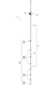
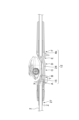
- FIG. 1 is a diagram showing a fishing rod according to an embodiment of the present invention. It is a figure showing a reel seat concerning one embodiment of the present invention.
- 1 shows an exploded perspective view of a reel seat according to an embodiment of the present invention.
- FIG. 3 is a diagram showing a cross section of a reel seat according to an embodiment of the present invention.
- FIG. 3 is a diagram showing a cross section of a reel seat according to an embodiment of the present invention.
- (a) It is an upper perspective view of the movable hood in the reel seat based on one Embodiment of this invention.
- (b) It is a downward perspective view of the movable hood in the reel seat based on one Embodiment of this invention. It is a figure explaining the bending rigidity of the reel seat 9 concerning one embodiment of the present invention.
- FIG. 1 is a diagram showing an embodiment of a fishing rod according to the present invention.
- a fishing rod 1 according to an embodiment of the present invention includes a rod body 2, a reel 6 attached to the rod body 2 via a reel seat 9, a fishing line guide 10 attached to the rod body 2, Equipped with
- each of the reel seat 9 and the fishing line guide 10 corresponds to an attachment component that is attached to the outer peripheral surface of the rod body.
- the rod body 2 is configured by, for example, connecting a base rod 3, a middle rod 5, a tip rod 7, and the like. These rod bodies are, for example, joined in a side-by-side manner.
- the base rod 3, the middle rod 5, and the tip rod 7 may be joined by a drawing method, a reverse joint method, a spigot method, or any other known joining method.
- the rod body 2 may be composed of a single rod body.
- the base rod 3, the middle rod 5, and the tip rod 7 are made of, for example, a tubular body made of fiber-reinforced resin.
- This fiber-reinforced resin tubular body is created by winding a fiber-reinforced resin prepreg (pre-preg sheet) in which reinforcing fibers are impregnated with a matrix resin around a core metal, and heating and curing the prepreg sheet.
- a fiber-reinforced resin prepreg pre-preg sheet
- reinforcing fibers contained in this prepreg sheet carbon fibers, glass fibers, and any other known reinforcing fibers other than these can be used, for example.
- a thermosetting resin such as an epoxy resin can be used as the matrix resin contained in the prepreg sheet. After the prepreg sheet is cured, the core metal is removed. Further, the outer surface of the tubular body is polished as appropriate.
- Each rod body may be configured in a solid shape.
- the main rod 3, the middle rod 5, and the tip rod 7 are provided with a plurality of fishing line guides 10 (fishing line guides 10A to 10D) that guide the fishing line reeled out from the reel 6 attached to the reel seat 9.
- the main rod 3 is provided with a fishing line guide 10A
- the middle rod 5 is provided with a fishing line guide 10B
- the tip rod 7 is provided with a fishing line guide 10C.
- a top guide 10D is provided at the tip of the tip rod 7, but its details will be omitted.
- the axial direction (front-back direction) and the up-down direction mean the direction shown in FIG. 2, and the left-right direction (side direction) means the direction perpendicular to the paper plane of FIG.
- the front means the tip side of the fishing rod
- the rear means the base end side
- the upper side means the reel side with respect to the axis X of the main rod (pole rod) when a double-bearing reel is installed
- the lower side means the means the opposite side.
- the reel seat body 12 includes a reel leg mounting surface 12a along the axial direction on which the reel leg 6a of the fishing reel 6 is mounted.
- the reel seat body 12 can be configured to have a length in the range of, for example, 150 mm to 200 mm, but is not limited thereto.
- this reel seat body 12 has the opposite side of the reel leg mounting surface 12a slightly bulged out, so that when the reel seat body 12 is gripped with the hand that is gripping it, it supports the ball of the foot or the vicinity thereof, so that it can be gripped easily.
- a bulging portion (trigger) 12b having an easily curved outer surface is formed. Note that the rod body may be connected to the rear side of the reel seat body 12.
- the reel leg placement surface 12a of the reel seat body 12 is flat or substantially flat with a larger curvature than other circumferential portions (for example, the trigger 12b) adjacent to the reel leg placement surface 12a of the reel seat body 12. It is formed in a state extending in the axial direction of the reel seat main body 12 shown in FIG.
- a fixed hood 14 is integrally disposed at one end (rod base side) of the reel seat body 12.
- One end of the reel leg mounting surface 12a of the reel seat body 12 is disposed inside the fixed hood 14.
- a movable hood 13 is attached to the other end (rod tip side) of the reel seat body 12 so as to be movable in the axial direction.
- the fishing reel 200 is mounted by placing the reel leg 6a on the reel leg mounting portion 12a, fitting the rear end into the fixed hood 14, and tightening the front end with the movable hood 13 that moves in the axial direction. It is attached and fixed to the reel seat 9.
- the reel seat 9 includes the reel seat main body 12 and the movable hood 13, but may include members other than these.
- the reel seat 9 according to an embodiment of the present invention includes a reel leg placement portion 12a on which the reel leg 6a is placed, and an axial rear side (the rod butt side) of the reel leg placement portion 12a.
- a reel seat body 12 comprising a fixed hood 14 provided on the reel leg mounting portion 12a, and a partially cut-out cylindrical portion 15 provided on the axially front side (the rod tip side) of the reel leg mounting portion 12a;
- a movable hood 13 provided on the axially forward side (rod tip side) of the reel leg mounting portion 12a, and a nut member provided on the outer surface of the cylindrical portion 15 to enable the movable hood 13 to move by rotation.
- the reel seat 9 is attached to the rod body 2
- the cylindrical portion 15 has a cylindrical portion 21 and a partially cutout recessed portion 22
- the movable hood 13 includes:
- the nut member 18 has an engaging portion 16 provided on the inner surface of the cylindrical portion 15 and a hood portion 17 that accommodates at least a portion of the reel leg 6a.
- the inner surface 18a of the nut member 18 engages with the engaging portion 16, and the rotation of the nut member 18 moves the movable hood 13 to the rear side in the axial direction (the rod butt side). ), and the rod body 2 is configured to be able to be inserted up to the cylindrical portion 21 of the cylindrical portion 15.
- the reel seat body 12 of the reel seat 9 is provided with a cylindrical portion 15 at the front, and a grip portion (rear grip) 23 to be gripped and held is fixed at the rear.
- the reel seat body 12 includes an intermediate connecting portion 24 that connects the cylindrical portion 15 and the rear cylindrical portion 4b in the axial direction, and these are integrally formed.
- the proximal outer peripheral surface of the rod body 2 constituting the fishing rod is fixed to the inner surface of the cylindrical portion 15 by adhesive or the like, and the grip portion 23 is formed to protrude from the rear side of the reel seat body 12 along the axial direction.
- the rear cylinder part 4b is also a part that is gripped and held together with the grip part 23, and can constitute a grip.
- the configuration of the fishing rod 1 to which the reel seat 9 is fixed is not limited, such as a swing-out type, a joint type, a single rod, etc., and in FIG. ) are shown, and the overall configuration is omitted. Further, an example is shown in which a low-profile double-bearing reel (hereinafter also referred to as a reel) is attached and fixed to the reel seat 9 as the fishing reel 6.
- the movable hood 13 includes an engaging portion 16 formed with a male thread, and a hood portion 17 curved inward in the radial direction and housing at least a portion of the reel leg 6a.
- the hood part 17 is disposed so as to fit into an opening 8 formed below the front end surface of the intermediate connecting part 24 (the end surface of the cylindrical part 15), and this opening 8 is arranged so as to fit into the opening 8 where the reel leg is placed. It is connected to section 12a. That is, when the movable hood 13 moves rearward, the hood portion 17 fits into the front end portion of the reel leg 6a placed on the reel leg placement portion 12a within the opening 8.
- the male threaded portion of the engaging portion 16 of the movable hood 13 is threaded with the female threaded portion formed on the inner surface 18a of the nut member 18 that is externally fitted into the cylindrical portion 15 (or the concave portion 22 of the cylindrical portion 15). It is made to match. That is, by rotating the nut member 18 in one direction, the movable hood 13 moves rearward in the axial direction, tightens the front end side of the reel leg 6a (reel attachment, fixed state), and rotates the nut member 18 in the other direction. By rotating the movable hood 13, the movable hood 13 moves forward in the axial direction and opens the front end side of the reel leg 6a (reel removed state).
- the method of engaging the engaging portion 16 with the inner surface of the nut member 18 may be various conventionally known methods, and is not limited to a specific form (screwing). Note that a circumferential groove is formed along the circumferential direction on the front end side of the cylindrical portion 15, and by attaching a ring-shaped member (retaining ring) 20 to this portion, the nut member 18 can be moved forward. It can be regulated to prevent it from falling out.
- a grip support part 25 is adhered to the outer surface of the reel seat body 12 adjacent to the nut member 18, and a grip part (front grip) 26 is fixed on the grip support part 25, and the nut member is rotatably operated.
- the grip portion 26 is provided so as to be flush with the surface of the grip portion 18, a configuration may be adopted in which the grip portion 26 is not provided.
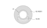
- FIG. 5 shows a cross section taken along line AA in FIG.
- the reel seat 9 according to the embodiment of the present invention has an axis of the cylindrical portion 15 when the rod body 2 is inserted (and the movable hood 13 is in the position shown in FIG. 2).
- the rod body 2, the movable hood (the engaging portion 16), the reel seat body 12 (cylindrical portion 15 or cylindrical portion 21) is provided in this order.
- the cylindrical portion 21 of the cylindrical portion 15 of the reel seat body 12 has a circular or approximately circular outer surface, and an engaging portion 16 that is curved with the cylindrical rod body 2 on the inner surface. It forms a space that can accommodate.
- the shape of the inside of the cylindrical portion 21 can be variously considered depending on the dimensions of the rod body and the shape of the engaging portion 16, and is not limited to a specific form.
- the rod body 2 is arranged in the thicker part of the reel seat body 12 (the cylindrical part 21 of the cylindrical part 15 is in the concave shape).
- the position of the reel leg resting part of the reel seat is offset in the direction of falling with respect to the axis of the main rod rod, by making it possible to insert up to the part (thickness than part 22)
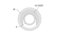
- FIG. 4 shows a cross section taken along line BB in FIG.
- the reel seat 9 according to the embodiment of the present invention has an axis of the cylindrical portion 15 when the rod body 2 is inserted (and the movable hood 13 is in the position shown in FIG. 2).
- the rod body 2, the reel seat body 12 (cylindrical 15 or concave portion 22), and the nut member 18, and the cross section perpendicular to the axial direction of the cylindrical portion 15 is arranged in the downward direction from the central axis of the cylindrical portion 15 (in the vertical direction of the paper in FIG. 4).
- the rod body 2 and the nut member 18 are provided in this order from the inside when viewed in the direction (direction), and a space through which the movable hood 13 passes is formed between the rod body 2 and the nut member 18.
- the engaging portion 16 of the movable hood 13 is made capable of moving back and forth in the axial direction of the reel seat 9 through the notched portion of the concave portion 22 of the cylindrical portion 15.
- the concave portion 22 is formed in a concave shape with an opening in the downward direction, thereby reducing the weight of the cylindrical portion 15 of the reel seat body 12.
- the cylindrical part 15 includes the cylindrical part 21 and the concave part 22, and although it does not form a perfect cylindrical shape, it is possible to form the cylindrical part 15 with a part cut out. (The same applies throughout this specification).
- the structure of the movable hood 13 in the reel seat 9 will be described.
- 6(a) and 6(b) are both perspective views (the former is viewed diagonally from above, and the latter is viewed diagonally from below).
- the movable hood 13 includes an engaging part 16 and a hood part 17, and when viewed in a cross section perpendicular to the axial direction of the cylindrical part 15 (the cross section shown in FIG. 4), the engaging part 16 is , arcuate or curved.
- the inner surface is firmly attached to the surface of the rod body 2, and the male threaded portion provided on the outer surface is screwed into the female threaded portion formed on the inner surface 18a of the nut member 18. becomes possible.
- the engaging portion 16 of the movable hood 13 is formed into an arc shape, and the angle of the arc is in the range of 70 degrees to 90 degrees.
- the engaging portion 16 and the hood portion 17 are arranged in the radial direction of the central axis of the reel seat 9.
- the hood portion 17 is formed inside the engaging portion 16 when viewed in the radial direction of the central axis of the reel seat 9.
- the engaging portion 16 and the hood portion 17 are offset, there is a gap between the engaging portion 16 and the hood portion 17 that extends perpendicularly to the central axis of the reel seat 9, and It has a connecting part 19 that connects the joining part 16 and the hood part 17.
- the reel seat 9 includes a reel leg placement part 12a on which the reel leg 6a is placed, and a fixed hood provided on the axial front side or rear side of the reel leg placement part 12a. 14, a cylindrical portion 15 provided on the rear or front side of the reel leg mounting portion 12a in the axial direction, and an intermediate connection that connects the cylindrical portion 15 and the front or rear cylindrical portion 4b in the axial direction.
- a reel seat main body 12 comprising a section 24; a movable hood 13 provided on the axial rear side or front side of the reel leg mounting section 12a;
- a reel seat 9 that is attached to the rod body 2 and includes a nut member 18 that makes the movable hood movable, the bending rigidity of the intermediate connecting portion 24 of the reel sheet body 12 being equal to that of the base portion of the rod body.
- the bending stiffness of the bending stiffness is the same as or lower than the bending stiffness of the bending stiffness.
- the reel seat 9 even when a structure is adopted in which the position of the reel leg placement part of the reel seat is offset in the downward direction with respect to the axis of the main rod, By adjusting the bending rigidity of the cylindrical part of the reel seat and the intermediate connecting part, stress concentration at the base of the rod tube is prevented, and even with an offset structure, the rod tube base is less likely to be damaged and the rod It becomes possible to provide a reel seat that can significantly increase the durability and strength of the reel sheet, and a fishing rod equipped with the reel seat.
- the reel seat 9 in the downward direction of the up-down direction of the reel seat 9 (up-down direction shown in FIG. 2 (up-down direction shown in FIG. 7 described later), hereinafter the same)
- the bending rigidity of the intermediate connecting portion 24 of the reel seat body 12 with respect to the bending rigidity of the cylindrical portion 15 of the main body 12 ranges from 0.8 to 1.0. In this way, the durability (or strength) of the rod can be improved.
- the bending rigidity of the lower part of the reel mounting portion of the reel seat main body is set to be 4 to 6 times greater in the lateral direction than in the longitudinal direction. In this way, it is possible to improve casting accuracy.
- FIG. 7 and the table below show the bending rigidity at each position when viewed in the stretching direction of the reel sheet.
- Position A is the position of the nut engaging part of the cylindrical part 15
- position B is the position of the front part of the reel stand of the cylindrical part 15.
- position C is the position of the lowest rigidity part of the lower part of the reel stand of the intermediate connecting part 24
- position D is the position of the convex part of the lower part of the reel stand of the intermediate connecting part
- position E is the position of the lowest rigid part of the lower part of the reel stand of the intermediate connecting part 24.
- This is the position of the front of the trigger.
- the position F is the position of the connection part of the rear cylinder part 4b with the grip. position This is the location of stress concentration in the main rod tube (base of the rod body).
- the bending rigidity (in the vertical direction) at positions B and F is 63.7 and 66.9, respectively, and is configured to be larger than at other positions.
- the bending rigidity (in the vertical direction) is lower than at positions B and F, but is 42.8.
- the bending rigidity (in the vertical direction) is 5.1, 7.6, and 6.4, respectively, which are lower than at position B. In this way, it is possible to lower the minimum rigidity with respect to the rod tube base rigidity of 6.0.
- the bending rigidity (lateral direction) at positions C, D, and E is 27.5, 33.0, and 33.9, respectively, which is 4.9 times to 5.4 times the vertical direction. I know that there is.
- the convex part at the finger hooking position D and the tip of the reel leg 6a are provided.
- the bending rigidity at the nearby position E is lowered.
- the minimum bending stiffness of the reel seat body 12 is set to be 80% to 100% of the bending stiffness at position Z.
- the fishing rod is swung in the lateral direction of the reel seat body 12, but in order to reduce shaking during casting, the lateral bending rigidity of the reel seat body 12 is increased. do. Specifically, by setting the bending rigidity value as described above, it is possible to improve casting accuracy.
- a fishing rod 1 is configured to include one of the reel seats 9 described above and a rod body 2.
- a structure is adopted in which the position of the reel leg mounting portion of the reel seat is offset in a downward direction with respect to the axis of the main rod rod. Also, by adjusting the bending rigidity of the cylindrical part of the reel seat and the intermediate connecting part, stress concentration at the base of the rod tube is prevented, and even with an offset structure, it is difficult to break at the base of the rod tube. It becomes possible to provide a reel sheet that can significantly increase the durability and strength of the rod, and a fishing rod equipped with the same.
- the reel seat body 12 can be formed of carbon fiber reinforced plastic (CFRP), glass reinforced plastic (GFRP), Al, or Mg.
- the reel sheet 12 may be made of GFRTP (continuous fiber), GFRTP (discontinuous fiber), CFRTP (continuous fiber), CFRTP (discontinuous fiber), or a hybrid.
- each component described herein is not limited to those explicitly described in the embodiments, and each component may be any number that may fall within the scope of the present invention. dimensions, materials, and arrangements. Further, components not explicitly described in this specification can be added to the described embodiments, or some of the components described in each embodiment can be omitted.
Landscapes
- Life Sciences & Earth Sciences (AREA)
- Environmental Sciences (AREA)
- Marine Sciences & Fisheries (AREA)
- Animal Husbandry (AREA)
- Biodiversity & Conservation Biology (AREA)
- Fishing Rods (AREA)
Priority Applications (1)
| Application Number | Priority Date | Filing Date | Title |
|---|---|---|---|
| CN202380065838.6A CN120225053A (zh) | 2022-09-13 | 2023-04-20 | 卷线器座及钓竿 |
Applications Claiming Priority (2)
| Application Number | Priority Date | Filing Date | Title |
|---|---|---|---|
| JP2022-145482 | 2022-09-13 | ||
| JP2022145482A JP7835653B2 (ja) | 2022-09-13 | 2022-09-13 | リールシート及び釣竿 |
Publications (1)
| Publication Number | Publication Date |
|---|---|
| WO2024057601A1 true WO2024057601A1 (ja) | 2024-03-21 |
Family
ID=90274440
Family Applications (1)
| Application Number | Title | Priority Date | Filing Date |
|---|---|---|---|
| PCT/JP2023/015743 Ceased WO2024057601A1 (ja) | 2022-09-13 | 2023-04-20 | リールシート及び釣竿 |
Country Status (3)
| Country | Link |
|---|---|
| JP (1) | JP7835653B2 (https=) |
| CN (1) | CN120225053A (https=) |
| WO (1) | WO2024057601A1 (https=) |
Citations (3)
| Publication number | Priority date | Publication date | Assignee | Title |
|---|---|---|---|---|
| JP2002084928A (ja) * | 2000-09-07 | 2002-03-26 | Shimano Inc | 元 竿 |
| JP2007202402A (ja) * | 2006-01-30 | 2007-08-16 | Daiwa Seiko Inc | 釣竿 |
| JP5898504B2 (ja) * | 2012-01-19 | 2016-04-06 | 株式会社シマノ | リールシート |
-
2022
- 2022-09-13 JP JP2022145482A patent/JP7835653B2/ja active Active
-
2023
- 2023-04-20 CN CN202380065838.6A patent/CN120225053A/zh active Pending
- 2023-04-20 WO PCT/JP2023/015743 patent/WO2024057601A1/ja not_active Ceased
Patent Citations (3)
| Publication number | Priority date | Publication date | Assignee | Title |
|---|---|---|---|---|
| JP2002084928A (ja) * | 2000-09-07 | 2002-03-26 | Shimano Inc | 元 竿 |
| JP2007202402A (ja) * | 2006-01-30 | 2007-08-16 | Daiwa Seiko Inc | 釣竿 |
| JP5898504B2 (ja) * | 2012-01-19 | 2016-04-06 | 株式会社シマノ | リールシート |
Also Published As
| Publication number | Publication date |
|---|---|
| CN120225053A (zh) | 2025-06-27 |
| JP7835653B2 (ja) | 2026-03-25 |
| JP2024040854A (ja) | 2024-03-26 |
Similar Documents
| Publication | Publication Date | Title |
|---|---|---|
| JP7376449B2 (ja) | リールシート | |
| WO2023210053A1 (ja) | リールシート及び釣竿 | |
| JP7500827B2 (ja) | 釣竿用リールシート及び釣竿 | |
| WO2024057601A1 (ja) | リールシート及び釣竿 | |
| JP7365316B2 (ja) | 釣竿用リールシート及び釣竿 | |
| JP2023160649A (ja) | リールシート及び釣竿 | |
| US12501890B2 (en) | Reel seat and fishing rod | |
| JP7661277B2 (ja) | グリップ構造及び釣竿 | |
| JP7798751B2 (ja) | リールシート及び釣竿 | |
| JP2023161505A (ja) | 釣竿 | |
| AU2021438460B2 (en) | Fishing line guide and fishing rod equipped with said fishing line guide | |
| JP6898221B2 (ja) | 釣竿用リールシート及び釣竿 | |
| JP2009131200A (ja) | 釣竿 | |
| JP3245620U (ja) | 釣竿用リールシートのナット、釣竿用リールシート及び釣竿 | |
| JP4148855B2 (ja) | 竿体の製造方法 | |
| JP2007020498A (ja) | 穂先竿 | |
| JP2011087503A (ja) | 釣り竿 | |
| JP3961980B2 (ja) | 釣竿 | |
| CN117897051A (zh) | 卷线器座把手部件、卷线器座把手构造以及钓竿 | |
| JPH11127733A (ja) | 穂先竿体 | |
| JP2004173561A (ja) | 釣竿 |
Legal Events
| Date | Code | Title | Description |
|---|---|---|---|
| 121 | Ep: the epo has been informed by wipo that ep was designated in this application |
Ref document number: 23864967 Country of ref document: EP Kind code of ref document: A1 |
|
| WWE | Wipo information: entry into national phase |
Ref document number: 202380065838.6 Country of ref document: CN |
|
| NENP | Non-entry into the national phase |
Ref country code: DE |
|
| WWP | Wipo information: published in national office |
Ref document number: 202380065838.6 Country of ref document: CN |
|
| 122 | Ep: pct application non-entry in european phase |
Ref document number: 23864967 Country of ref document: EP Kind code of ref document: A1 |