WO2024057601A1 - Reel seat and fishing rod - Google Patents
Reel seat and fishing rod Download PDFInfo
- Publication number
- WO2024057601A1 WO2024057601A1 PCT/JP2023/015743 JP2023015743W WO2024057601A1 WO 2024057601 A1 WO2024057601 A1 WO 2024057601A1 JP 2023015743 W JP2023015743 W JP 2023015743W WO 2024057601 A1 WO2024057601 A1 WO 2024057601A1
- Authority
- WO
- WIPO (PCT)
- Prior art keywords
- reel
- rod
- reel seat
- seat
- cylindrical part
- Prior art date
Links
- 238000005452 bending Methods 0.000 claims abstract description 40
- 230000000994 depressogenic effect Effects 0.000 abstract 1
- 229920005989 resin Polymers 0.000 description 7
- 239000011347 resin Substances 0.000 description 7
- 238000000034 method Methods 0.000 description 6
- 238000005266 casting Methods 0.000 description 4
- 238000010586 diagram Methods 0.000 description 4
- 239000000835 fiber Substances 0.000 description 4
- 239000000463 material Substances 0.000 description 4
- 230000002093 peripheral effect Effects 0.000 description 3
- 239000012783 reinforcing fiber Substances 0.000 description 3
- 241000251468 Actinopterygii Species 0.000 description 2
- 239000004918 carbon fiber reinforced polymer Substances 0.000 description 2
- 239000011199 continuous fiber reinforced thermoplastic Substances 0.000 description 2
- 239000011152 fibreglass Substances 0.000 description 2
- 239000011159 matrix material Substances 0.000 description 2
- 239000002184 metal Substances 0.000 description 2
- 229920000049 Carbon (fiber) Polymers 0.000 description 1
- 241001391944 Commicarpus scandens Species 0.000 description 1
- 239000000853 adhesive Substances 0.000 description 1
- 230000001070 adhesive effect Effects 0.000 description 1
- 239000004917 carbon fiber Substances 0.000 description 1
- 239000003822 epoxy resin Substances 0.000 description 1
- 239000003365 glass fiber Substances 0.000 description 1
- 238000010438 heat treatment Methods 0.000 description 1
- 239000007769 metal material Substances 0.000 description 1
- 229920000647 polyepoxide Polymers 0.000 description 1
- 230000001105 regulatory effect Effects 0.000 description 1
- 230000000284 resting effect Effects 0.000 description 1
- 239000007787 solid Substances 0.000 description 1
- 229920001187 thermosetting polymer Polymers 0.000 description 1
- 238000004804 winding Methods 0.000 description 1
Images


Classifications
-
- A—HUMAN NECESSITIES
- A01—AGRICULTURE; FORESTRY; ANIMAL HUSBANDRY; HUNTING; TRAPPING; FISHING
- A01K—ANIMAL HUSBANDRY; CARE OF BIRDS, FISHES, INSECTS; FISHING; REARING OR BREEDING ANIMALS, NOT OTHERWISE PROVIDED FOR; NEW BREEDS OF ANIMALS
- A01K87/00—Fishing rods
- A01K87/06—Devices for fixing reels on rods
Definitions
- a fishing rod reel seat and a fishing rod grip are usually placed on the rod body, and the fishing rod reel sheet includes a reel for placing the reel leg on the upper or lower side of the fishing rod body. A leg rest is formed.
- Patent Document 1 describes a high-rigidity part X located on the rod base side of the reel seat 8 and a low-rigidity part that is lower in rigidity than the high-rigidity part X located on the tip side of the high-rigidity part X.
- This base rod 1 has a high rigidity portion It is disclosed that this part is difficult to bend because it maintains such rigidity that it is possible to support the entire fishing rod by pulling the base rod in a stable state.
- a reel seat 4 is attached to the base rod 2
- a fishing line guide 6 is attached to the tip side portion 1a located on the tip side of the tip rod 1
- the tip side portion 1a is attached to the fishing line guide 6. It is constructed to be more rigid than the rod butt side portion 1b located on the rod butt side from the rod tip side portion 1a, and the rod butt side portion 1b is held in a state housed within the base rod 2, and the rod butt side portion 1b is Disclosed is a retractable swinging rod in which the side portion 1b is configured to be able to be held in an extended state in which the main rod 2 is pulled out toward the tip side, and in which the rod butt side portion 1b is easily bent by being pulled by a fish in the extended state. ing.
- fishing rods have been used in which the rigidity of the tip of the reel seat body is higher than the rigidity of the base of the rod tube.
- fishing rods using an offset reel seat have a structure in which the rod tube does not penetrate the offset reel seat.
- the reel seat body is made of metal material, or if it is made of resin material, the reel seat body is made thicker to ensure strength. The rigidity of will increase.
- stress concentration will occur on the rod tube at the tip of the reel seat, causing damage to the rod tube. It has been found that the problem of ease of use occurs.
- the main rod according to Patent Document 1 has a problem in that stress concentration occurs in the low-rigidity portion Y, which is lower in rigidity than the high-rigidity portion X located on the tip side of the high-rigidity portion X.
- the fishing rod according to Patent Document 2 only has higher rigidity than the rod tip side portion, which is located closer to the rod bottom side than the rod tip side portion, and stress concentration is caused in the rod tube at the tip of the reel seat. This did not solve the problem of the rod tube being easily damaged.
- the present invention has been made in view of the above circumstances, and its purpose is to adopt a structure in which the position of the reel leg mounting portion of the reel seat is offset in the downward direction with respect to the axis of the main rod rod. Even in such cases, by adjusting the bending rigidity of the cylindrical part of the reel seat and the intermediate connecting part, stress concentration at the rod base can be prevented, and even with an offset structure, the rod base can be To provide a reel sheet that is not easily damaged at the parts and can greatly increase the durability and strength of the rod, and a fishing rod equipped with the reel sheet.
- a reel seat includes: a reel leg placement portion on which a reel leg is placed; a fixed hood provided on the axial front side or rear side of the reel leg placement portion;
- a reel seat body comprising: a cylindrical part provided on the axial rear side or the front side of the leg rest part; and an intermediate connecting part that connects the cylindrical part and the front or rear cylindrical part in the axial direction; , comprising a movable hood provided on the rear side or the front side in the axial direction of the reel leg mounting portion, and a nut member provided on the outer surface of the cylindrical portion to enable the movable hood to be moved by rotation.
- the reel seat is attached to a rod body, and the bending rigidity of the intermediate connecting portion of the reel sheet body is the same as or lower than the bending rigidity of the base portion of the rod body.
- the bending rigidity of the intermediate connecting portion of the reel sheet body relative to the bending rigidity of the base portion of the rod body in the downward direction of the vertical direction of the reel sheet is 0.8.
- the range is from 1.0 to 1.0.
- the bending rigidity of the lower part of the reel mounting portion of the reel seat main body is set to be 4 to 6 times greater in the lateral direction than in the longitudinal direction.
- a fishing rod according to an embodiment of the present invention is configured to include any one of the above reel seats and a rod body.
- FIG. 1 is a diagram showing a fishing rod according to an embodiment of the present invention. It is a figure showing a reel seat concerning one embodiment of the present invention.
- 1 shows an exploded perspective view of a reel seat according to an embodiment of the present invention.
- FIG. 3 is a diagram showing a cross section of a reel seat according to an embodiment of the present invention.
- FIG. 3 is a diagram showing a cross section of a reel seat according to an embodiment of the present invention.
- (a) It is an upper perspective view of the movable hood in the reel seat based on one Embodiment of this invention.
- (b) It is a downward perspective view of the movable hood in the reel seat based on one Embodiment of this invention. It is a figure explaining the bending rigidity of the reel seat 9 concerning one embodiment of the present invention.
- FIG. 1 is a diagram showing an embodiment of a fishing rod according to the present invention.
- a fishing rod 1 according to an embodiment of the present invention includes a rod body 2, a reel 6 attached to the rod body 2 via a reel seat 9, a fishing line guide 10 attached to the rod body 2, Equipped with
- each of the reel seat 9 and the fishing line guide 10 corresponds to an attachment component that is attached to the outer peripheral surface of the rod body.
- the rod body 2 is configured by, for example, connecting a base rod 3, a middle rod 5, a tip rod 7, and the like. These rod bodies are, for example, joined in a side-by-side manner.
- the base rod 3, the middle rod 5, and the tip rod 7 may be joined by a drawing method, a reverse joint method, a spigot method, or any other known joining method.
- the rod body 2 may be composed of a single rod body.
- the base rod 3, the middle rod 5, and the tip rod 7 are made of, for example, a tubular body made of fiber-reinforced resin.
- This fiber-reinforced resin tubular body is created by winding a fiber-reinforced resin prepreg (pre-preg sheet) in which reinforcing fibers are impregnated with a matrix resin around a core metal, and heating and curing the prepreg sheet.
- a fiber-reinforced resin prepreg pre-preg sheet
- reinforcing fibers contained in this prepreg sheet carbon fibers, glass fibers, and any other known reinforcing fibers other than these can be used, for example.
- a thermosetting resin such as an epoxy resin can be used as the matrix resin contained in the prepreg sheet. After the prepreg sheet is cured, the core metal is removed. Further, the outer surface of the tubular body is polished as appropriate.
- Each rod body may be configured in a solid shape.
- the main rod 3, the middle rod 5, and the tip rod 7 are provided with a plurality of fishing line guides 10 (fishing line guides 10A to 10D) that guide the fishing line reeled out from the reel 6 attached to the reel seat 9.
- the main rod 3 is provided with a fishing line guide 10A
- the middle rod 5 is provided with a fishing line guide 10B
- the tip rod 7 is provided with a fishing line guide 10C.
- a top guide 10D is provided at the tip of the tip rod 7, but its details will be omitted.
- the axial direction (front-back direction) and the up-down direction mean the direction shown in FIG. 2, and the left-right direction (side direction) means the direction perpendicular to the paper plane of FIG.
- the front means the tip side of the fishing rod
- the rear means the base end side
- the upper side means the reel side with respect to the axis X of the main rod (pole rod) when a double-bearing reel is installed
- the lower side means the means the opposite side.
- the reel seat body 12 includes a reel leg mounting surface 12a along the axial direction on which the reel leg 6a of the fishing reel 6 is mounted.
- the reel seat body 12 can be configured to have a length in the range of, for example, 150 mm to 200 mm, but is not limited thereto.
- this reel seat body 12 has the opposite side of the reel leg mounting surface 12a slightly bulged out, so that when the reel seat body 12 is gripped with the hand that is gripping it, it supports the ball of the foot or the vicinity thereof, so that it can be gripped easily.
- a bulging portion (trigger) 12b having an easily curved outer surface is formed. Note that the rod body may be connected to the rear side of the reel seat body 12.
- the reel leg placement surface 12a of the reel seat body 12 is flat or substantially flat with a larger curvature than other circumferential portions (for example, the trigger 12b) adjacent to the reel leg placement surface 12a of the reel seat body 12. It is formed in a state extending in the axial direction of the reel seat main body 12 shown in FIG.
- a fixed hood 14 is integrally disposed at one end (rod base side) of the reel seat body 12.
- One end of the reel leg mounting surface 12a of the reel seat body 12 is disposed inside the fixed hood 14.
- a movable hood 13 is attached to the other end (rod tip side) of the reel seat body 12 so as to be movable in the axial direction.
- the fishing reel 200 is mounted by placing the reel leg 6a on the reel leg mounting portion 12a, fitting the rear end into the fixed hood 14, and tightening the front end with the movable hood 13 that moves in the axial direction. It is attached and fixed to the reel seat 9.
- the reel seat 9 includes the reel seat main body 12 and the movable hood 13, but may include members other than these.
- the reel seat 9 according to an embodiment of the present invention includes a reel leg placement portion 12a on which the reel leg 6a is placed, and an axial rear side (the rod butt side) of the reel leg placement portion 12a.
- a reel seat body 12 comprising a fixed hood 14 provided on the reel leg mounting portion 12a, and a partially cut-out cylindrical portion 15 provided on the axially front side (the rod tip side) of the reel leg mounting portion 12a;
- a movable hood 13 provided on the axially forward side (rod tip side) of the reel leg mounting portion 12a, and a nut member provided on the outer surface of the cylindrical portion 15 to enable the movable hood 13 to move by rotation.
- the reel seat 9 is attached to the rod body 2
- the cylindrical portion 15 has a cylindrical portion 21 and a partially cutout recessed portion 22
- the movable hood 13 includes:
- the nut member 18 has an engaging portion 16 provided on the inner surface of the cylindrical portion 15 and a hood portion 17 that accommodates at least a portion of the reel leg 6a.
- the inner surface 18a of the nut member 18 engages with the engaging portion 16, and the rotation of the nut member 18 moves the movable hood 13 to the rear side in the axial direction (the rod butt side). ), and the rod body 2 is configured to be able to be inserted up to the cylindrical portion 21 of the cylindrical portion 15.
- the reel seat body 12 of the reel seat 9 is provided with a cylindrical portion 15 at the front, and a grip portion (rear grip) 23 to be gripped and held is fixed at the rear.
- the reel seat body 12 includes an intermediate connecting portion 24 that connects the cylindrical portion 15 and the rear cylindrical portion 4b in the axial direction, and these are integrally formed.
- the proximal outer peripheral surface of the rod body 2 constituting the fishing rod is fixed to the inner surface of the cylindrical portion 15 by adhesive or the like, and the grip portion 23 is formed to protrude from the rear side of the reel seat body 12 along the axial direction.
- the rear cylinder part 4b is also a part that is gripped and held together with the grip part 23, and can constitute a grip.
- the configuration of the fishing rod 1 to which the reel seat 9 is fixed is not limited, such as a swing-out type, a joint type, a single rod, etc., and in FIG. ) are shown, and the overall configuration is omitted. Further, an example is shown in which a low-profile double-bearing reel (hereinafter also referred to as a reel) is attached and fixed to the reel seat 9 as the fishing reel 6.
- the movable hood 13 includes an engaging portion 16 formed with a male thread, and a hood portion 17 curved inward in the radial direction and housing at least a portion of the reel leg 6a.
- the hood part 17 is disposed so as to fit into an opening 8 formed below the front end surface of the intermediate connecting part 24 (the end surface of the cylindrical part 15), and this opening 8 is arranged so as to fit into the opening 8 where the reel leg is placed. It is connected to section 12a. That is, when the movable hood 13 moves rearward, the hood portion 17 fits into the front end portion of the reel leg 6a placed on the reel leg placement portion 12a within the opening 8.
- the male threaded portion of the engaging portion 16 of the movable hood 13 is threaded with the female threaded portion formed on the inner surface 18a of the nut member 18 that is externally fitted into the cylindrical portion 15 (or the concave portion 22 of the cylindrical portion 15). It is made to match. That is, by rotating the nut member 18 in one direction, the movable hood 13 moves rearward in the axial direction, tightens the front end side of the reel leg 6a (reel attachment, fixed state), and rotates the nut member 18 in the other direction. By rotating the movable hood 13, the movable hood 13 moves forward in the axial direction and opens the front end side of the reel leg 6a (reel removed state).
- the method of engaging the engaging portion 16 with the inner surface of the nut member 18 may be various conventionally known methods, and is not limited to a specific form (screwing). Note that a circumferential groove is formed along the circumferential direction on the front end side of the cylindrical portion 15, and by attaching a ring-shaped member (retaining ring) 20 to this portion, the nut member 18 can be moved forward. It can be regulated to prevent it from falling out.
- a grip support part 25 is adhered to the outer surface of the reel seat body 12 adjacent to the nut member 18, and a grip part (front grip) 26 is fixed on the grip support part 25, and the nut member is rotatably operated.
- the grip portion 26 is provided so as to be flush with the surface of the grip portion 18, a configuration may be adopted in which the grip portion 26 is not provided.
- FIG. 5 shows a cross section taken along line AA in FIG.
- the reel seat 9 according to the embodiment of the present invention has an axis of the cylindrical portion 15 when the rod body 2 is inserted (and the movable hood 13 is in the position shown in FIG. 2).
- the rod body 2, the movable hood (the engaging portion 16), the reel seat body 12 (cylindrical portion 15 or cylindrical portion 21) is provided in this order.
- the cylindrical portion 21 of the cylindrical portion 15 of the reel seat body 12 has a circular or approximately circular outer surface, and an engaging portion 16 that is curved with the cylindrical rod body 2 on the inner surface. It forms a space that can accommodate.
- the shape of the inside of the cylindrical portion 21 can be variously considered depending on the dimensions of the rod body and the shape of the engaging portion 16, and is not limited to a specific form.
- the rod body 2 is arranged in the thicker part of the reel seat body 12 (the cylindrical part 21 of the cylindrical part 15 is in the concave shape).
- the position of the reel leg resting part of the reel seat is offset in the direction of falling with respect to the axis of the main rod rod, by making it possible to insert up to the part (thickness than part 22)
- FIG. 4 shows a cross section taken along line BB in FIG.
- the reel seat 9 according to the embodiment of the present invention has an axis of the cylindrical portion 15 when the rod body 2 is inserted (and the movable hood 13 is in the position shown in FIG. 2).
- the rod body 2, the reel seat body 12 (cylindrical 15 or concave portion 22), and the nut member 18, and the cross section perpendicular to the axial direction of the cylindrical portion 15 is arranged in the downward direction from the central axis of the cylindrical portion 15 (in the vertical direction of the paper in FIG. 4).
- the rod body 2 and the nut member 18 are provided in this order from the inside when viewed in the direction (direction), and a space through which the movable hood 13 passes is formed between the rod body 2 and the nut member 18.
- the engaging portion 16 of the movable hood 13 is made capable of moving back and forth in the axial direction of the reel seat 9 through the notched portion of the concave portion 22 of the cylindrical portion 15.
- the concave portion 22 is formed in a concave shape with an opening in the downward direction, thereby reducing the weight of the cylindrical portion 15 of the reel seat body 12.
- the cylindrical part 15 includes the cylindrical part 21 and the concave part 22, and although it does not form a perfect cylindrical shape, it is possible to form the cylindrical part 15 with a part cut out. (The same applies throughout this specification).
- the structure of the movable hood 13 in the reel seat 9 will be described.
- 6(a) and 6(b) are both perspective views (the former is viewed diagonally from above, and the latter is viewed diagonally from below).
- the movable hood 13 includes an engaging part 16 and a hood part 17, and when viewed in a cross section perpendicular to the axial direction of the cylindrical part 15 (the cross section shown in FIG. 4), the engaging part 16 is , arcuate or curved.
- the inner surface is firmly attached to the surface of the rod body 2, and the male threaded portion provided on the outer surface is screwed into the female threaded portion formed on the inner surface 18a of the nut member 18. becomes possible.
- the engaging portion 16 of the movable hood 13 is formed into an arc shape, and the angle of the arc is in the range of 70 degrees to 90 degrees.
- the engaging portion 16 and the hood portion 17 are arranged in the radial direction of the central axis of the reel seat 9.
- the hood portion 17 is formed inside the engaging portion 16 when viewed in the radial direction of the central axis of the reel seat 9.
- the engaging portion 16 and the hood portion 17 are offset, there is a gap between the engaging portion 16 and the hood portion 17 that extends perpendicularly to the central axis of the reel seat 9, and It has a connecting part 19 that connects the joining part 16 and the hood part 17.
- the reel seat 9 includes a reel leg placement part 12a on which the reel leg 6a is placed, and a fixed hood provided on the axial front side or rear side of the reel leg placement part 12a. 14, a cylindrical portion 15 provided on the rear or front side of the reel leg mounting portion 12a in the axial direction, and an intermediate connection that connects the cylindrical portion 15 and the front or rear cylindrical portion 4b in the axial direction.
- a reel seat main body 12 comprising a section 24; a movable hood 13 provided on the axial rear side or front side of the reel leg mounting section 12a;
- a reel seat 9 that is attached to the rod body 2 and includes a nut member 18 that makes the movable hood movable, the bending rigidity of the intermediate connecting portion 24 of the reel sheet body 12 being equal to that of the base portion of the rod body.
- the bending stiffness of the bending stiffness is the same as or lower than the bending stiffness of the bending stiffness.
- the reel seat 9 even when a structure is adopted in which the position of the reel leg placement part of the reel seat is offset in the downward direction with respect to the axis of the main rod, By adjusting the bending rigidity of the cylindrical part of the reel seat and the intermediate connecting part, stress concentration at the base of the rod tube is prevented, and even with an offset structure, the rod tube base is less likely to be damaged and the rod It becomes possible to provide a reel seat that can significantly increase the durability and strength of the reel sheet, and a fishing rod equipped with the reel seat.
- the reel seat 9 in the downward direction of the up-down direction of the reel seat 9 (up-down direction shown in FIG. 2 (up-down direction shown in FIG. 7 described later), hereinafter the same)
- the bending rigidity of the intermediate connecting portion 24 of the reel seat body 12 with respect to the bending rigidity of the cylindrical portion 15 of the main body 12 ranges from 0.8 to 1.0. In this way, the durability (or strength) of the rod can be improved.
- the bending rigidity of the lower part of the reel mounting portion of the reel seat main body is set to be 4 to 6 times greater in the lateral direction than in the longitudinal direction. In this way, it is possible to improve casting accuracy.
- FIG. 7 and the table below show the bending rigidity at each position when viewed in the stretching direction of the reel sheet.
- Position A is the position of the nut engaging part of the cylindrical part 15
- position B is the position of the front part of the reel stand of the cylindrical part 15.
- position C is the position of the lowest rigidity part of the lower part of the reel stand of the intermediate connecting part 24
- position D is the position of the convex part of the lower part of the reel stand of the intermediate connecting part
- position E is the position of the lowest rigid part of the lower part of the reel stand of the intermediate connecting part 24.
- This is the position of the front of the trigger.
- the position F is the position of the connection part of the rear cylinder part 4b with the grip. position This is the location of stress concentration in the main rod tube (base of the rod body).
- the bending rigidity (in the vertical direction) at positions B and F is 63.7 and 66.9, respectively, and is configured to be larger than at other positions.
- the bending rigidity (in the vertical direction) is lower than at positions B and F, but is 42.8.
- the bending rigidity (in the vertical direction) is 5.1, 7.6, and 6.4, respectively, which are lower than at position B. In this way, it is possible to lower the minimum rigidity with respect to the rod tube base rigidity of 6.0.
- the bending rigidity (lateral direction) at positions C, D, and E is 27.5, 33.0, and 33.9, respectively, which is 4.9 times to 5.4 times the vertical direction. I know that there is.
- the convex part at the finger hooking position D and the tip of the reel leg 6a are provided.
- the bending rigidity at the nearby position E is lowered.
- the minimum bending stiffness of the reel seat body 12 is set to be 80% to 100% of the bending stiffness at position Z.
- the fishing rod is swung in the lateral direction of the reel seat body 12, but in order to reduce shaking during casting, the lateral bending rigidity of the reel seat body 12 is increased. do. Specifically, by setting the bending rigidity value as described above, it is possible to improve casting accuracy.
- a fishing rod 1 is configured to include one of the reel seats 9 described above and a rod body 2.
- a structure is adopted in which the position of the reel leg mounting portion of the reel seat is offset in a downward direction with respect to the axis of the main rod rod. Also, by adjusting the bending rigidity of the cylindrical part of the reel seat and the intermediate connecting part, stress concentration at the base of the rod tube is prevented, and even with an offset structure, it is difficult to break at the base of the rod tube. It becomes possible to provide a reel sheet that can significantly increase the durability and strength of the rod, and a fishing rod equipped with the same.
- the reel seat body 12 can be formed of carbon fiber reinforced plastic (CFRP), glass reinforced plastic (GFRP), Al, or Mg.
- the reel sheet 12 may be made of GFRTP (continuous fiber), GFRTP (discontinuous fiber), CFRTP (continuous fiber), CFRTP (discontinuous fiber), or a hybrid.
- each component described herein is not limited to those explicitly described in the embodiments, and each component may be any number that may fall within the scope of the present invention. dimensions, materials, and arrangements. Further, components not explicitly described in this specification can be added to the described embodiments, or some of the components described in each embodiment can be omitted.
Abstract
Provided are a reel seat and a fishing rod comprising the reel seat, the reel seat being configured so that, even in the case of using a structure in which the position of a reel leg mounting part of the reel seat is offset in a depressed direction with respect to the axial center of a base rod, it is possible to prevent the generation of stress concentration at a rod pipe base part by adjusting the bending rigidity at a cylindrical part and an intermediate connection part of the reel seat, and as a result of the foregoing, the rod pipe base part is hard to break even with the offset structure and it is possible to greatly increase the rigidity and strength of the rod. The reel seat according to one embodiment of the present invention is to be attached to a rod body, and comprises: a reel seat body provided with a reel leg mounting part on which a reel leg is mounted, a fixed hood provided to the front side or the rear side in the axial direction of the reel leg mounting part, a cylindrical part provided to the rear side or the front side in the axial direction of the reel leg mounting part, and an intermediate connection part that connects the cylindrical part and a front or rear cylindrical part along the axial direction; a movable hood provided to the rear side or the front side in the axial direction of the reel leg mounting part; and a nut member provided to an outer surface of the cylindrical part, and capable of rotating so as to move the movable hood. The bending rigidity of the intermediate connection part of the reel seat body is configured to be lower than or equal to the bending rigidity of a base part of the rod body.
Description
相互参照
本出願は、日本国特許出願2022-145482(2022年9月13日出願)に基づく優先権を主張し、その内容は参照により全体として本明細書に組み込まれる。
本発明は、リールシート、及びこれを備えた釣竿に関する。 Cross-reference This application claims priority based on Japanese Patent Application No. 2022-145482 (filed on September 13, 2022), the contents of which are incorporated herein by reference in their entirety.
The present invention relates to a reel seat and a fishing rod equipped with the same.
従来より、釣竿用リールシートを備えた様々な釣竿が知られている。
Conventionally, various fishing rods equipped with fishing rod reel seats have been known.
このような釣竿では、通常、竿体の上に釣竿用リールシートや釣竿用グリップが載置され、該釣竿用リールシートには、本体の上側又は下側にリール脚を載置するためのリール脚載置部が形成される。
In such fishing rods, a fishing rod reel seat and a fishing rod grip are usually placed on the rod body, and the fishing rod reel sheet includes a reel for placing the reel leg on the upper or lower side of the fishing rod body. A leg rest is formed.
このような釣竿として、例えば、特許文献1には、リールシート8の竿元側に位置する高剛性部分X及び高剛性部分Xの穂先側に位置する高剛性部分Xより剛性の低い低剛性部分Yとを有するこの元竿1であって、釣人がリールシート8付近を把持しつつ竿元側端部を肘に当てまたは腹に当てて元竿1を支えても、高剛性部分Xが充分な剛性を維持しているのでこの部分が湾曲し難く、安定した状態で元竿1引いては釣竿全体を支えることが可能であることが開示されている。
As such a fishing rod, for example, Patent Document 1 describes a high-rigidity part X located on the rod base side of the reel seat 8 and a low-rigidity part that is lower in rigidity than the high-rigidity part X located on the tip side of the high-rigidity part X. This base rod 1 has a high rigidity portion It is disclosed that this part is difficult to bend because it maintains such rigidity that it is possible to support the entire fishing rod by pulling the base rod in a stable state.
また、特許文献2には、元竿2にリールシート4を装着するとともに、穂先竿1の竿先側に位置する竿先側部分1aに釣り糸ガイド6を装着し、竿先側部分1aを、その竿先側部分1aより竿尻側に位置する竿尻側部分1bに比べて高剛性なものに構成し、竿尻側部分1bを元竿2内に収納した状態で保持するとともに、竿尻側部分1bを元竿2の竿先側に引き出した伸長状態に保持可能に構成するとともに、伸長状態で竿尻側部分1bが魚の引きを受けて曲がり易くなっている伸縮式振出竿が開示されている。
Furthermore, in Patent Document 2, a reel seat 4 is attached to the base rod 2, a fishing line guide 6 is attached to the tip side portion 1a located on the tip side of the tip rod 1, and the tip side portion 1a is attached to the fishing line guide 6. It is constructed to be more rigid than the rod butt side portion 1b located on the rod butt side from the rod tip side portion 1a, and the rod butt side portion 1b is held in a state housed within the base rod 2, and the rod butt side portion 1b is Disclosed is a retractable swinging rod in which the side portion 1b is configured to be able to be held in an extended state in which the main rod 2 is pulled out toward the tip side, and in which the rod butt side portion 1b is easily bent by being pulled by a fish in the extended state. ing.
従来より、リールシート本体先部剛性が、竿管の元部剛性よりも高い構造の釣竿が用いられ、特に、オフセットリールシートを使用した釣竿では、竿管が該オフセットリールシートを貫通しない構造が採用されている場合、リールシートの強度を維持する為に、金属材料でリールシート本体を作成したり、樹脂材料の場合には、肉厚を厚くして強度を確保することで、リールシート本体の剛性が大きくなってしまう。しかしながら、竿管に負荷が掛かった場合、竿管が継がれたリールシート先端部の剛性が高くなっていると、それによりリールシート先部の竿管に応力集中が起き、竿管が破損し易いという問題が発生することが見出された。この点、特許文献1に係る元竿では、高剛性部分Xの穂先側に位置する高剛性部分Xより剛性の低い低剛性部分Yに応力集中が起きるという問題があった。他方で、特許文献2に係る釣竿では、竿先側部分より竿尻側に位置する竿尻側部分に比べて高剛性なものとするに過ぎず、リールシート先部の竿管に応力集中が起き、竿管が破損し易いという問題を解決できるものではなかった。
Traditionally, fishing rods have been used in which the rigidity of the tip of the reel seat body is higher than the rigidity of the base of the rod tube. In particular, fishing rods using an offset reel seat have a structure in which the rod tube does not penetrate the offset reel seat. If adopted, in order to maintain the strength of the reel seat, the reel seat body is made of metal material, or if it is made of resin material, the reel seat body is made thicker to ensure strength. The rigidity of will increase. However, when a load is applied to the rod tube, if the rigidity of the tip of the reel seat to which the rod tube is connected is high, stress concentration will occur on the rod tube at the tip of the reel seat, causing damage to the rod tube. It has been found that the problem of ease of use occurs. In this regard, the main rod according to Patent Document 1 has a problem in that stress concentration occurs in the low-rigidity portion Y, which is lower in rigidity than the high-rigidity portion X located on the tip side of the high-rigidity portion X. On the other hand, the fishing rod according to Patent Document 2 only has higher rigidity than the rod tip side portion, which is located closer to the rod bottom side than the rod tip side portion, and stress concentration is caused in the rod tube at the tip of the reel seat. This did not solve the problem of the rod tube being easily damaged.
本発明は上記の事情に鑑みてなされたものであり、その目的とするところは、リールシートのリール脚載置部の位置が元竿杆の軸心に対して落ち込む方向にオフセットした構造を採用した場合であっても、リールシートの筒状部と中間連結部における曲げ剛性を調整することで、竿管元部における応力集中の発生を防止し、これによりオフセット構造であっても竿管元部で破損し難く、竿の耐久性及び強度を大幅に高めることが可能なリールシート、及びこれを備えた釣竿を提供することにある。本発明のこれら以外の目的は、本明細書全体を参照することにより明らかとなる。
The present invention has been made in view of the above circumstances, and its purpose is to adopt a structure in which the position of the reel leg mounting portion of the reel seat is offset in the downward direction with respect to the axis of the main rod rod. Even in such cases, by adjusting the bending rigidity of the cylindrical part of the reel seat and the intermediate connecting part, stress concentration at the rod base can be prevented, and even with an offset structure, the rod base can be To provide a reel sheet that is not easily damaged at the parts and can greatly increase the durability and strength of the rod, and a fishing rod equipped with the reel sheet. These and other objects of the invention will become apparent upon reference to the entire specification.
本発明の一実施形態に係るリールシートは、リール脚が載置されるリール脚載置部と、該リール脚載置部の軸方向前方側又は後方側に設けられた固定フードと、該リール脚載置部の軸方向後方側又は前方側に設けられる筒状部と、該筒状部と前方又は後方の筒部を軸方向に亘って連結する中間連結部と、を備えるリールシート本体と、該リール脚載置部の軸方向後方側又は前方側に設けられた移動フードと、該筒状部の外面に設けられ、回転により該移動フードを移動可能とするナット部材と、を備える、竿体に取付けられるリールシートであって、前記リールシート本体の前記中間連結部の曲げ剛性が、前記竿体の元部の曲げ剛性と同じかそれよりも低くなるようにされる。
A reel seat according to an embodiment of the present invention includes: a reel leg placement portion on which a reel leg is placed; a fixed hood provided on the axial front side or rear side of the reel leg placement portion; A reel seat body comprising: a cylindrical part provided on the axial rear side or the front side of the leg rest part; and an intermediate connecting part that connects the cylindrical part and the front or rear cylindrical part in the axial direction; , comprising a movable hood provided on the rear side or the front side in the axial direction of the reel leg mounting portion, and a nut member provided on the outer surface of the cylindrical portion to enable the movable hood to be moved by rotation. The reel seat is attached to a rod body, and the bending rigidity of the intermediate connecting portion of the reel sheet body is the same as or lower than the bending rigidity of the base portion of the rod body.
本発明の一実施形態に係るリールシートにおいて、前記リールシートの上下方向の下方方向における、前記竿体の元部の曲げ剛性に対する前記リールシート本体の前記中間連結部の曲げ剛性が、0.8から1.0までの範囲である。
In the reel sheet according to an embodiment of the present invention, the bending rigidity of the intermediate connecting portion of the reel sheet body relative to the bending rigidity of the base portion of the rod body in the downward direction of the vertical direction of the reel sheet is 0.8. The range is from 1.0 to 1.0.
本発明の一実施形態に係るリールシートにおいて、前記リールシート本体リール載置部下部の曲げ剛性は、その縦方向に対してその横方向が4倍~6倍となるようにされる。
In the reel seat according to an embodiment of the present invention, the bending rigidity of the lower part of the reel mounting portion of the reel seat main body is set to be 4 to 6 times greater in the lateral direction than in the longitudinal direction.
本発明の一実施形態に係る釣竿は、上記いずれかのリールシートと、竿体とを備えるように構成される。
A fishing rod according to an embodiment of the present invention is configured to include any one of the above reel seats and a rod body.
上記実施形態によれば、リールシートのリール脚載置部の位置が元竿杆の軸心に対して落ち込む方向にオフセットした構造を採用した場合であっても、リールシートの筒状部と中間連結部における曲げ剛性を調整することで、竿管元部における応力集中の発生を防止し、これによりオフセット構造であっても竿管元部で破損し難く、竿の耐久性及び強度を大幅に高めることが可能なリールシート、及びこれを備えた釣竿を提供することが可能となる。
According to the above embodiment, even if a structure is adopted in which the position of the reel leg placement part of the reel seat is offset in the downward direction with respect to the axis of the main rod, the cylindrical part of the reel seat and the By adjusting the bending rigidity at the connecting part, stress concentration at the base of the rod tube is prevented, and even with an offset structure, it is difficult to break at the base of the rod tube, greatly increasing the durability and strength of the rod. It becomes possible to provide a reel seat that can be raised and a fishing rod equipped with the reel seat.
以下、本発明に係るリールシート及び釣竿の実施形態について、添付図面を参照しながら具体的に説明する。複数の図面において共通する構成要素には当該複数の図面を通じて同一の参照符号が付されている。各図面は、説明の便宜上、必ずしも正確な縮尺で記載されているとは限らない点に留意されたい。
Hereinafter, embodiments of a reel seat and a fishing rod according to the present invention will be specifically described with reference to the accompanying drawings. Components that are common in multiple drawings are given the same reference numerals throughout the multiple drawings. It should be noted that the drawings are not necessarily drawn to scale for illustrative purposes.
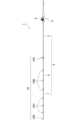
図1は、本発明に係る釣竿の一実施形態を示す図である。図示のように、本発明の一実施形態による釣竿1は、竿体2と、竿体2にリールシート9を介して取り付けられたリール6と、竿体2に取り付けられた釣糸ガイド10と、を備える。図示の実施形態においては、リールシート9及び釣糸ガイド10の各々が、竿体の外周面に取り付けられる取付部品に該当する。
FIG. 1 is a diagram showing an embodiment of a fishing rod according to the present invention. As illustrated, a fishing rod 1 according to an embodiment of the present invention includes a rod body 2, a reel 6 attached to the rod body 2 via a reel seat 9, a fishing line guide 10 attached to the rod body 2, Equipped with In the illustrated embodiment, each of the reel seat 9 and the fishing line guide 10 corresponds to an attachment component that is attached to the outer peripheral surface of the rod body.
竿体2は、例えば、元竿3、中竿5、及び穂先竿7等を連結することによって構成されている。これらの各竿体は、例えば、並継ぎ式に継合される。元竿3、中竿5、及び穂先竿7は、振出方式、逆並継方式、インロー方式、又はこれら以外の公知の任意の継合方式により継合され得る。竿体2は、単一の竿体から構成されていても良い。
The rod body 2 is configured by, for example, connecting a base rod 3, a middle rod 5, a tip rod 7, and the like. These rod bodies are, for example, joined in a side-by-side manner. The base rod 3, the middle rod 5, and the tip rod 7 may be joined by a drawing method, a reverse joint method, a spigot method, or any other known joining method. The rod body 2 may be composed of a single rod body.
元竿3、中竿5、及び穂先竿7は、例えば、繊維強化樹脂製の管状体で構成されている。この繊維強化樹脂製の管状体は、強化繊維にマトリクス樹脂を含浸させた繊維強化樹脂プリプレグ(プリプレグシート)を芯金に巻回し、このプリプレグシートを加熱して硬化させることにより作成される。このプリプレグシートに含まれる強化繊維として、例えば、炭素繊維、ガラス繊維、及びこれら以外の任意の公知の強化繊維を用いることができる。当該プリプレグシートに含まれるマトリクス樹脂として、エポキシ樹脂等の熱硬化性樹脂を用いることができる。プリプレグシートが硬化された後には、芯金が脱芯される。また、管状体の外表面は、適宜研磨される。各竿体は、中実状に構成されてもよい。
The base rod 3, the middle rod 5, and the tip rod 7 are made of, for example, a tubular body made of fiber-reinforced resin. This fiber-reinforced resin tubular body is created by winding a fiber-reinforced resin prepreg (pre-preg sheet) in which reinforcing fibers are impregnated with a matrix resin around a core metal, and heating and curing the prepreg sheet. As the reinforcing fibers contained in this prepreg sheet, carbon fibers, glass fibers, and any other known reinforcing fibers other than these can be used, for example. A thermosetting resin such as an epoxy resin can be used as the matrix resin contained in the prepreg sheet. After the prepreg sheet is cured, the core metal is removed. Further, the outer surface of the tubular body is polished as appropriate. Each rod body may be configured in a solid shape.
図示の実施形態において、元竿3、中竿5及び穂先竿7には、リールシート9に装着されるリール6から繰り出される釣糸を案内する複数の釣糸ガイド10(釣糸ガイド10A~10D)が設けられている。より具体的には、元竿3には釣糸ガイド10Aが設けられ、中竿5には釣糸ガイド10Bが設けられ、穂先竿7には釣糸ガイド10Cが設けられている。穂先竿7の先端には、トップガイド10Dが設けられているが、詳細は省略する。
In the illustrated embodiment, the main rod 3, the middle rod 5, and the tip rod 7 are provided with a plurality of fishing line guides 10 (fishing line guides 10A to 10D) that guide the fishing line reeled out from the reel 6 attached to the reel seat 9. It is being More specifically, the main rod 3 is provided with a fishing line guide 10A, the middle rod 5 is provided with a fishing line guide 10B, and the tip rod 7 is provided with a fishing line guide 10C. A top guide 10D is provided at the tip of the tip rod 7, but its details will be omitted.
次に、図2を参照して、リールシート本体12及びリールシート9の基本的構成につき説明する。以下の説明において、軸方向(前後方向)及び上下方向は、図2で示した方向を意味し、左右方向(サイド方向)は、図2の紙面と直交する方向を意味する。すなわち、前方は釣竿の穂先側、後方は基端側を意味し、上方は、両軸受けリールを装着した際、元竿杆(竿杆)の軸心Xに対してリール側、下方は、その反対側を意味する。
Next, the basic configurations of the reel seat body 12 and the reel seat 9 will be explained with reference to FIG. 2. In the following description, the axial direction (front-back direction) and the up-down direction mean the direction shown in FIG. 2, and the left-right direction (side direction) means the direction perpendicular to the paper plane of FIG. In other words, the front means the tip side of the fishing rod, the rear means the base end side, the upper side means the reel side with respect to the axis X of the main rod (pole rod) when a double-bearing reel is installed, and the lower side means the means the opposite side.
リールシート本体12は、魚釣用リール6のリール脚6aが載置されるリール脚載置面12aをその軸方向に沿って有するリールシート本体12を備えている。リールシート本体12は、例えば、150mmから200mmの範囲の長さを有するよう構成できるが、これに限られない。また、このリールシート本体12は、リール脚載置面12aの反対側を僅かに膨出させ、握持する手で握り込んだときに、母指球またはその近部を支えることで握持し易い湾曲形状の外面を有する膨出部(トリガー)12bを形成してある。なお、リールシート本体12の後側に竿体を継ぐような構成にしてもよい。
The reel seat body 12 includes a reel leg mounting surface 12a along the axial direction on which the reel leg 6a of the fishing reel 6 is mounted. The reel seat body 12 can be configured to have a length in the range of, for example, 150 mm to 200 mm, but is not limited thereto. In addition, this reel seat body 12 has the opposite side of the reel leg mounting surface 12a slightly bulged out, so that when the reel seat body 12 is gripped with the hand that is gripping it, it supports the ball of the foot or the vicinity thereof, so that it can be gripped easily. A bulging portion (trigger) 12b having an easily curved outer surface is formed. Note that the rod body may be connected to the rear side of the reel seat body 12.
リールシート本体12のリール脚載置面12aは、平坦または、リールシート本体12のリール脚載置面12aに隣接する他の周方向の部位(例えば、トリガー12b)よりも大きな曲率をもって略平坦に形成することができ、かつ、図2に示すリールシート本体12の軸方向に延びた状態に形成されている。リールシート本体12には、一端(竿元側)に固定フード14が一体的に配設されている。リールシート本体12のリール脚載置面12aの一端は、固定フード14の内部に配設されている。
The reel leg placement surface 12a of the reel seat body 12 is flat or substantially flat with a larger curvature than other circumferential portions (for example, the trigger 12b) adjacent to the reel leg placement surface 12a of the reel seat body 12. It is formed in a state extending in the axial direction of the reel seat main body 12 shown in FIG. A fixed hood 14 is integrally disposed at one end (rod base side) of the reel seat body 12. One end of the reel leg mounting surface 12a of the reel seat body 12 is disposed inside the fixed hood 14.
リールシート本体12には、他端(竿先側)に移動フード13が軸方向に移動自在に装着される。リール脚載置部12aにリール脚6aを載置して、その後端側を固定フード14に嵌入した状態で、前端側を軸方向に移動する移動フード13で締め付けることで魚釣用リール200はリールシート9に装着、固定されるようになっている。なお、リールシート9は、該リールシート本体12と該移動フード13とを含むが、これら以外の部材を含み得る。
A movable hood 13 is attached to the other end (rod tip side) of the reel seat body 12 so as to be movable in the axial direction. The fishing reel 200 is mounted by placing the reel leg 6a on the reel leg mounting portion 12a, fitting the rear end into the fixed hood 14, and tightening the front end with the movable hood 13 that moves in the axial direction. It is attached and fixed to the reel seat 9. Note that the reel seat 9 includes the reel seat main body 12 and the movable hood 13, but may include members other than these.
再度図2を参照して、本発明の一実施形態に係るリールシートについてより詳細に説明する。図示のように、本発明の一実施形態に係るリールシート9は、リール脚6aが載置されるリール脚載置部12aと、該リール脚載置部12aの軸方向後方側(竿尻側)に設けられた固定フード14と、該リール脚載置部12aの軸方向前方側(竿先側)に設けられ、一部が切欠かれた筒状部15とを備えるリールシート本体12と、該リール脚載置部12aの軸方向前方側(竿先側)に設けられた移動フード13と、該筒状部15の外面に設けられ、回転により該移動フード13を移動可能とするナット部材18とを備える、竿体2に取付けられるリールシート9であって、該筒状部15は、円筒部21と、一部が切欠かれた凹状部22とを有し、該移動フード13は、該筒状部15の内面に設けられる係合部16と、該リール脚6aの少なくとも一部を収容するフード部17とを有し、該ナット部材18は、該凹状部22の外面に該凹状部22に対して相対回転可能に設けられ、該ナット部材18の内面18aが該係合部16と係合して該ナット部材18の回転により移動フード13を該軸方向後方側(竿尻側)に移動可能にされ、該竿体2は、該筒状部15の該円筒部21まで挿入可能にされるように構成される。
Referring again to FIG. 2, the reel seat according to one embodiment of the present invention will be described in more detail. As shown in the figure, the reel seat 9 according to an embodiment of the present invention includes a reel leg placement portion 12a on which the reel leg 6a is placed, and an axial rear side (the rod butt side) of the reel leg placement portion 12a. ), a reel seat body 12 comprising a fixed hood 14 provided on the reel leg mounting portion 12a, and a partially cut-out cylindrical portion 15 provided on the axially front side (the rod tip side) of the reel leg mounting portion 12a; A movable hood 13 provided on the axially forward side (rod tip side) of the reel leg mounting portion 12a, and a nut member provided on the outer surface of the cylindrical portion 15 to enable the movable hood 13 to move by rotation. 18, the reel seat 9 is attached to the rod body 2, the cylindrical portion 15 has a cylindrical portion 21 and a partially cutout recessed portion 22, and the movable hood 13 includes: The nut member 18 has an engaging portion 16 provided on the inner surface of the cylindrical portion 15 and a hood portion 17 that accommodates at least a portion of the reel leg 6a. The inner surface 18a of the nut member 18 engages with the engaging portion 16, and the rotation of the nut member 18 moves the movable hood 13 to the rear side in the axial direction (the rod butt side). ), and the rod body 2 is configured to be able to be inserted up to the cylindrical portion 21 of the cylindrical portion 15.
次に、図2及び3を参照して、本発明の一実施形態に係るリールシートについて更に説明する。リールシート9のリールシート本体12は、前方に、筒状部15を備えており、後方に、握持、保持されるグリップ部(後方グリップ)23が固定されるようになっている。該リールシート本体12は、筒状部15と後方筒部4bを軸方向に亘って連結する中間連結部24を備えており、これらは一体形成されている。筒状部15の内面には、釣竿を構成する竿体2の基端側外周面が接着等によって固定され、グリップ部23は、リールシート本体12の後方側に軸心方向に沿って突出形成された筒状突部4aの外周面に固定されており、後方筒部4bの表面と面一状になるように構成されている。この場合、後方筒部4bもグリップ部23と共に握持、保持される部分であり、グリップを構成し得る。なお、リールシート9が固定される釣竿1については、振出式、継合式、1本竿等、その構成については限定されることはなく、図2では、釣竿の一部(竿体の一部)が示され、全体構成については省略されている。また、該リールシート9は、魚釣用リール6として、ロープロファイル型の両軸受けリール(以下、リールとも称する)を装着、固定した例が示されている。
Next, a reel seat according to an embodiment of the present invention will be further described with reference to FIGS. 2 and 3. The reel seat body 12 of the reel seat 9 is provided with a cylindrical portion 15 at the front, and a grip portion (rear grip) 23 to be gripped and held is fixed at the rear. The reel seat body 12 includes an intermediate connecting portion 24 that connects the cylindrical portion 15 and the rear cylindrical portion 4b in the axial direction, and these are integrally formed. The proximal outer peripheral surface of the rod body 2 constituting the fishing rod is fixed to the inner surface of the cylindrical portion 15 by adhesive or the like, and the grip portion 23 is formed to protrude from the rear side of the reel seat body 12 along the axial direction. It is fixed to the outer peripheral surface of the cylindrical protrusion 4a, and is configured to be flush with the surface of the rear cylindrical portion 4b. In this case, the rear cylinder part 4b is also a part that is gripped and held together with the grip part 23, and can constitute a grip. The configuration of the fishing rod 1 to which the reel seat 9 is fixed is not limited, such as a swing-out type, a joint type, a single rod, etc., and in FIG. ) are shown, and the overall configuration is omitted. Further, an example is shown in which a low-profile double-bearing reel (hereinafter also referred to as a reel) is attached and fixed to the reel seat 9 as the fishing reel 6.
該移動フード13は、雄ネジ部が形成された係合部16と、該リール脚6aの少なくとも一部を収容する径方向内側に湾曲したフード部17を備える。該フード部17は、中間連結部24の前方端面(筒状部15の端面)の下方に形成された開口8内に入り込むように配設されており、この開口8は、該リール脚載置部12aと繋がっている。すなわち、移動フード13が後方側に移動すると、そのフード部17は、開口8内において、該リール脚載置部12aに載置されたリール脚6aの前端部に嵌入するようになっている。
The movable hood 13 includes an engaging portion 16 formed with a male thread, and a hood portion 17 curved inward in the radial direction and housing at least a portion of the reel leg 6a. The hood part 17 is disposed so as to fit into an opening 8 formed below the front end surface of the intermediate connecting part 24 (the end surface of the cylindrical part 15), and this opening 8 is arranged so as to fit into the opening 8 where the reel leg is placed. It is connected to section 12a. That is, when the movable hood 13 moves rearward, the hood portion 17 fits into the front end portion of the reel leg 6a placed on the reel leg placement portion 12a within the opening 8.
該移動フード13の係合部16の雄ネジ部は、筒状部15(又は筒状部15の凹状部22)に外嵌されるナット部材18の内面18aに形成された雌ネジ部と螺合するようにされる。すなわち、ナット部材18を一方向に回転操作することで、移動フード13は軸方向後方側に移動してリール脚6aの前端側を締め付け(リールの装着、固定状態)、ナット部材18を他方向に回転操作することで、移動フード13は軸方向前方側に移動して、リール脚6aの前端側を開放する(リールの取り外し状態)。ここで、係合部16とナット部材18の内面との係合方法は、従来公知の様々な方法が考えられ、特定の態様(螺合)に限定されるものではない。なお、筒状部15の前端側には、周方向に沿って円周溝が形成されており、この部分にリング状部材(止め輪)20を装着することで、ナット部材18が前方側に抜けないように規制することができる。
The male threaded portion of the engaging portion 16 of the movable hood 13 is threaded with the female threaded portion formed on the inner surface 18a of the nut member 18 that is externally fitted into the cylindrical portion 15 (or the concave portion 22 of the cylindrical portion 15). It is made to match. That is, by rotating the nut member 18 in one direction, the movable hood 13 moves rearward in the axial direction, tightens the front end side of the reel leg 6a (reel attachment, fixed state), and rotates the nut member 18 in the other direction. By rotating the movable hood 13, the movable hood 13 moves forward in the axial direction and opens the front end side of the reel leg 6a (reel removed state). Here, the method of engaging the engaging portion 16 with the inner surface of the nut member 18 may be various conventionally known methods, and is not limited to a specific form (screwing). Note that a circumferential groove is formed along the circumferential direction on the front end side of the cylindrical portion 15, and by attaching a ring-shaped member (retaining ring) 20 to this portion, the nut member 18 can be moved forward. It can be regulated to prevent it from falling out.
リールシート本体12の外面には、ナット部材18に隣接してグリップ支持部25が接着され、該グリップ支持部25上にグリップ部(前方グリップ)26が固定されており、回転操作されるナット部材18の表面と面一状になるように設けられているが、グリップ部26を設けない構成であってもよい。
A grip support part 25 is adhered to the outer surface of the reel seat body 12 adjacent to the nut member 18, and a grip part (front grip) 26 is fixed on the grip support part 25, and the nut member is rotatably operated. Although the grip portion 26 is provided so as to be flush with the surface of the grip portion 18, a configuration may be adopted in which the grip portion 26 is not provided.
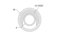
次に、図5を参照して、本発明の一実施形態に係るリールシート9の断面構造について説明する。図5は、図2のA-A断面を示すものである。図示のように、本発明の一実施形態に係るリールシート9は、該竿体2が挿入された状態(かつ移動フード13が図2の位置にある場合)で、該筒状部15の軸方向に垂直な断面を該筒状部15の中心軸から下方方向(図5の紙面の上下方向の下方向)に向かう方向でみて、内側から該竿体2、該移動フード(該係合部16)、該リールシート本体12(筒状部15又は円筒部21)が順に設けられる。図示のように、リールシート本体12の筒状部15の円筒部21は、外面が円形又は略円形の形状をなし、内面は円筒状の竿体2と湾曲して形成される係合部16とを収容可能な空間を形成している。円筒部21の内部の形状は、竿体の寸法や係合部16の形状により種々考えられ、特定の態様に限定されるものではない。
Next, with reference to FIG. 5, a cross-sectional structure of the reel seat 9 according to an embodiment of the present invention will be described. FIG. 5 shows a cross section taken along line AA in FIG. As shown in the figure, the reel seat 9 according to the embodiment of the present invention has an axis of the cylindrical portion 15 when the rod body 2 is inserted (and the movable hood 13 is in the position shown in FIG. 2). The rod body 2, the movable hood (the engaging portion 16), the reel seat body 12 (cylindrical portion 15 or cylindrical portion 21) is provided in this order. As shown in the figure, the cylindrical portion 21 of the cylindrical portion 15 of the reel seat body 12 has a circular or approximately circular outer surface, and an engaging portion 16 that is curved with the cylindrical rod body 2 on the inner surface. It forms a space that can accommodate. The shape of the inside of the cylindrical portion 21 can be variously considered depending on the dimensions of the rod body and the shape of the engaging portion 16, and is not limited to a specific form.
このようにして、本発明の一実施形態に係るリールシート9では、竿体2がリールシート本体12の内部の同リールシート本体のより肉厚の部分(筒状部15の円筒部21は凹状部22よりも肉厚になっている)まで挿入可能にされることで、リールシートのリール脚載置部の位置が元竿杆の軸心に対して落ち込む方向にオフセットした構造を採用した場合でも、丸型及びロープロファイルの両軸リールのいずれにも対応可能で、強度が低下しにくく耐久性を大幅に高めることが可能なリールシートを提供することが可能となる。
In this way, in the reel seat 9 according to an embodiment of the present invention, the rod body 2 is arranged in the thicker part of the reel seat body 12 (the cylindrical part 21 of the cylindrical part 15 is in the concave shape). When a structure is adopted in which the position of the reel leg resting part of the reel seat is offset in the direction of falling with respect to the axis of the main rod rod, by making it possible to insert up to the part (thickness than part 22) However, it is possible to provide a reel seat that is compatible with both round and low-profile dual-shaft reels and that is less likely to lose strength and can significantly increase durability.
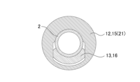
次に、図4を参照して、本発明の一実施形態に係るリールシート9の断面構造について説明する。図4は、図2のB-B断面を示すものである。図示のように、本発明の一実施形態に係るリールシート9は、該竿体2が挿入された状態(かつ移動フード13が図2の位置にある場合)で、該筒状部15の軸方向に垂直な断面を該筒状部15の中心軸から上方方向(図4の紙面の上下方向の上方向)に向かう方向でみて、内側から該竿体2、該リールシート本体12(筒状部15又は凹状部22)、ナット部材18の順に設けられ、該筒状部15の軸方向に垂直な断面を該筒状部15の中心軸から下方方向(図4の紙面の上下方向の下方向)に向かう方向でみて、内側から該竿体2、ナット部材18の順に設けられ、該竿体2とナット部材18との間に移動フード13が通る空間が形成されている。このようにして、移動フード13の係合部16は、筒状部15の凹状部22の切欠かれた部分を該リールシート9の軸方向に前後移動可能にされる。ここで、該凹状部22は、図4に示す通り、当該下方方向に開口を有する凹状に形成されており、これによりリールシート本体12の筒状部15の軽量化を図っている。このように、筒状部15は、円筒部21と凹状部22とを備えるものであり、完全なる筒状を形成するものではないが、その一部が切欠かれた筒状部15ということができる(本明細書を通じて同様とする)。
Next, with reference to FIG. 4, a cross-sectional structure of the reel seat 9 according to an embodiment of the present invention will be described. FIG. 4 shows a cross section taken along line BB in FIG. As shown in the figure, the reel seat 9 according to the embodiment of the present invention has an axis of the cylindrical portion 15 when the rod body 2 is inserted (and the movable hood 13 is in the position shown in FIG. 2). The rod body 2, the reel seat body 12 (cylindrical 15 or concave portion 22), and the nut member 18, and the cross section perpendicular to the axial direction of the cylindrical portion 15 is arranged in the downward direction from the central axis of the cylindrical portion 15 (in the vertical direction of the paper in FIG. 4). The rod body 2 and the nut member 18 are provided in this order from the inside when viewed in the direction (direction), and a space through which the movable hood 13 passes is formed between the rod body 2 and the nut member 18. In this way, the engaging portion 16 of the movable hood 13 is made capable of moving back and forth in the axial direction of the reel seat 9 through the notched portion of the concave portion 22 of the cylindrical portion 15. Here, as shown in FIG. 4, the concave portion 22 is formed in a concave shape with an opening in the downward direction, thereby reducing the weight of the cylindrical portion 15 of the reel seat body 12. In this way, the cylindrical part 15 includes the cylindrical part 21 and the concave part 22, and although it does not form a perfect cylindrical shape, it is possible to form the cylindrical part 15 with a part cut out. (The same applies throughout this specification).
次に、図6を参照して、本発明の一実施形態に係るリールシート9における移動フード13の構造について説明する。図6(a)、(b)は、いずれも斜視図(前者は、斜め上、後者は斜め下からみたもの)である。図示のように、移動フード13は、係合部16とフード部17とを備え、該筒状部15の軸方向に垂直な断面(図4に示す断面)でみて、該係合部16は、円弧状又は湾曲して形成されている。このようにして、内面が竿体2の表面に密着して確実に接着され、また、外面に設けられた雄ネジ部が、ナット部材18の内面18aに形成された雌ネジ部と螺合せしめることが可能となる。また、該移動フード13の該係合部16は、円弧状に形成される円弧の角度は、70度から90度の範囲である。
Next, with reference to FIG. 6, the structure of the movable hood 13 in the reel seat 9 according to an embodiment of the present invention will be described. 6(a) and 6(b) are both perspective views (the former is viewed diagonally from above, and the latter is viewed diagonally from below). As shown in the figure, the movable hood 13 includes an engaging part 16 and a hood part 17, and when viewed in a cross section perpendicular to the axial direction of the cylindrical part 15 (the cross section shown in FIG. 4), the engaging part 16 is , arcuate or curved. In this way, the inner surface is firmly attached to the surface of the rod body 2, and the male threaded portion provided on the outer surface is screwed into the female threaded portion formed on the inner surface 18a of the nut member 18. becomes possible. Further, the engaging portion 16 of the movable hood 13 is formed into an arc shape, and the angle of the arc is in the range of 70 degrees to 90 degrees.
また、図6に示すように、本発明の一実施形態に係るリールシートにおける移動フード13において、該係合部16と、該フード部17とは、該リールシート9の中心軸の径方向でみてオフセットされている(該リールシート9の中心軸の径方向でみて、該フード部17が、該係合部16よりも内側に形成されている)。また、該係合部16と、該フード部17とがオフセットされる場合、該係合部16と該フード部17との間に、該リールシート9の中心軸に垂直に延伸し、該係合部16と該フード部17とを接続する接続部19を有する。このようにして、接続部19の長さを調節することにより、竿体自体をリールシート本体が厚肉構造となる部分まで挿入可能となる。
Further, as shown in FIG. 6, in the movable hood 13 of the reel seat according to an embodiment of the present invention, the engaging portion 16 and the hood portion 17 are arranged in the radial direction of the central axis of the reel seat 9. (The hood portion 17 is formed inside the engaging portion 16 when viewed in the radial direction of the central axis of the reel seat 9.) In addition, when the engaging portion 16 and the hood portion 17 are offset, there is a gap between the engaging portion 16 and the hood portion 17 that extends perpendicularly to the central axis of the reel seat 9, and It has a connecting part 19 that connects the joining part 16 and the hood part 17. By adjusting the length of the connecting portion 19 in this manner, it becomes possible to insert the rod body itself up to the portion where the reel seat body has a thick structure.
本発明の一実施形態に係るリールシート9は、リール脚6aが載置されるリール脚載置部12aと、該リール脚載置部12aの軸方向前方側又は後方側に設けられた固定フード14と、該リール脚載置部12aの軸方向後方側又は前方側に設けられる筒状部15と、該筒状部15と前方又は後方の筒部4bを軸方向に亘って連結する中間連結部24と、を備えるリールシート本体12と、該リール脚載置部12aの軸方向後方側又は前方側に設けられた移動フード13と、該筒状部15の外面に設けられ、回転により該移動フードを移動可能とするナット部材18と、を備える、竿体2に取付けられるリールシート9であって、当該リールシート本体12の当該中間連結部24の曲げ剛性が、前記竿体の元部の曲げ剛性の曲げ剛性と同じかそれよりも低くなるようにされる。
The reel seat 9 according to an embodiment of the present invention includes a reel leg placement part 12a on which the reel leg 6a is placed, and a fixed hood provided on the axial front side or rear side of the reel leg placement part 12a. 14, a cylindrical portion 15 provided on the rear or front side of the reel leg mounting portion 12a in the axial direction, and an intermediate connection that connects the cylindrical portion 15 and the front or rear cylindrical portion 4b in the axial direction. a reel seat main body 12 comprising a section 24; a movable hood 13 provided on the axial rear side or front side of the reel leg mounting section 12a; A reel seat 9 that is attached to the rod body 2 and includes a nut member 18 that makes the movable hood movable, the bending rigidity of the intermediate connecting portion 24 of the reel sheet body 12 being equal to that of the base portion of the rod body. The bending stiffness of the bending stiffness is the same as or lower than the bending stiffness of the bending stiffness.
本発明の一実施形態に係るリールシート9によれば、リールシートのリール脚載置部の位置が元竿杆の軸心に対して落ち込む方向にオフセットした構造を採用した場合であっても、リールシートの筒状部と中間連結部における曲げ剛性を調整することで、竿管元部における応力集中の発生を防止し、これによりオフセット構造であっても竿管元部で破損し難く、竿の耐久性及び強度を大幅に高めることが可能なリールシート、及びこれを備えた釣竿を提供することが可能となる。
According to the reel seat 9 according to one embodiment of the present invention, even when a structure is adopted in which the position of the reel leg placement part of the reel seat is offset in the downward direction with respect to the axis of the main rod, By adjusting the bending rigidity of the cylindrical part of the reel seat and the intermediate connecting part, stress concentration at the base of the rod tube is prevented, and even with an offset structure, the rod tube base is less likely to be damaged and the rod It becomes possible to provide a reel seat that can significantly increase the durability and strength of the reel sheet, and a fishing rod equipped with the reel seat.
本発明の一実施形態に係るリールシート9において、リールシート9の上下方向の下方方向(図2に示す上下方向(後述する図7に示す上下方向)、以下同様とする)における、当該リールシート本体12の筒状部15の曲げ剛性に対する当該リールシート本体12の当該中間連結部24の曲げ剛性が、0.8から1.0までの範囲である。このようにして、竿の耐久性(又は強度)の向上が可能となる。
In the reel seat 9 according to an embodiment of the present invention, the reel seat 9 in the downward direction of the up-down direction of the reel seat 9 (up-down direction shown in FIG. 2 (up-down direction shown in FIG. 7 described later), hereinafter the same) The bending rigidity of the intermediate connecting portion 24 of the reel seat body 12 with respect to the bending rigidity of the cylindrical portion 15 of the main body 12 ranges from 0.8 to 1.0. In this way, the durability (or strength) of the rod can be improved.
本発明の一実施形態に係るリールシート9において、リールシート本体リール載置部下部の曲げ剛性は、その縦方向に対してその横方向が4倍~6倍となるようにされる。このようにして、キャステング精度の向上が可能となる。
In the reel seat 9 according to an embodiment of the present invention, the bending rigidity of the lower part of the reel mounting portion of the reel seat main body is set to be 4 to 6 times greater in the lateral direction than in the longitudinal direction. In this way, it is possible to improve casting accuracy.
次に、図7を参照して、本発明の一実施形態に係るリールシート9について更に説明する。図7及び下記表に示すのは、リールシートの延伸方向でみた各位置における曲げ剛性を示すものである。位置Aは、筒状部15のナット係合部の位置であり、位置Bは、筒状部15のリールスタンドの前部の位置である。また、位置Cは、中間連結部24のリールスタンド下部最低剛性部の位置であり、位置Dは、中間連結部24のリールスタンド下部の凸部の位置であり、位置Eは、中間連結部24のトリガー前部の位置である。また、位置Fは、後方筒部4bのグリップとの連結部の位置である。位置Xは元竿管(合わせ用部材)の後端部の位置であり、範囲Yは元竿管(合わせ用部材)とリールスタンド前部の間の範囲であり、位置Zは合わせ用部材27の元竿管(竿体の元部)の応力集中の位置である。
Next, with reference to FIG. 7, the reel seat 9 according to an embodiment of the present invention will be further described. FIG. 7 and the table below show the bending rigidity at each position when viewed in the stretching direction of the reel sheet. Position A is the position of the nut engaging part of the cylindrical part 15, and position B is the position of the front part of the reel stand of the cylindrical part 15. Further, position C is the position of the lowest rigidity part of the lower part of the reel stand of the intermediate connecting part 24, position D is the position of the convex part of the lower part of the reel stand of the intermediate connecting part 24, and position E is the position of the lowest rigid part of the lower part of the reel stand of the intermediate connecting part 24. This is the position of the front of the trigger. Moreover, the position F is the position of the connection part of the rear cylinder part 4b with the grip. position This is the location of stress concentration in the main rod tube (base of the rod body).
下記表に示す通り、位置B及び位置Fにおける曲げ剛性(上下方向)はそれぞれ63.7、66.9となり、その他の位置に比べて大きくなるように構成されている。位置Aでは、曲げ剛性(上下方向)は、位置B及び位置Fよりも低いが、42.8となっている。位置C、D及びEでは、曲げ剛性(上下方向)がそれぞれ5.1、7.6、6.4となり、位置Bよりも低くなっている。このようにして、竿管元部剛性6.0に対して、最低剛性を低くすることが可能となる。また、位置C、D及びEにおける曲げ剛性(横方向)はそれぞれ27.5、33.0、33.9となっており、上下方向に対して4.9倍から5.4倍となっていることが判る。
As shown in the table below, the bending rigidity (in the vertical direction) at positions B and F is 63.7 and 66.9, respectively, and is configured to be larger than at other positions. At position A, the bending rigidity (in the vertical direction) is lower than at positions B and F, but is 42.8. At positions C, D, and E, the bending rigidity (in the vertical direction) is 5.1, 7.6, and 6.4, respectively, which are lower than at position B. In this way, it is possible to lower the minimum rigidity with respect to the rod tube base rigidity of 6.0. In addition, the bending rigidity (lateral direction) at positions C, D, and E is 27.5, 33.0, and 33.9, respectively, which is 4.9 times to 5.4 times the vertical direction. I know that there is.
本発明の一実施形態に係るリールシートを備えた釣竿による魚とのやり取り時においては、魚釣用リールを上向きにした時に、穂先に下方向に力が加わる。この時、当該Yの範囲には応力が集中し破損し易いため曲げ剛性を高くする必要がある。他方で、リールシート本体12全体の曲げ剛性を高くした場合、上記位置Zの付近で応力が集中し破損し易くなることが判っている。そこで、リールシート本体12、リール脚載置部12aの下側の曲げ剛性を低くすることにより、位置Zでの応力集中を防ぐことが可能となる。また、リールシート下部全体が曲がりリールシート下部の特定部分に応力集中しリールシートの耐久性(又は強度)を低下させないようにするため、指を掛ける位置Dの凸部及びリール脚6aの先端部付近の位置Eにおける曲げ剛性を低くしている。また、リールシート本体12の最低曲げ剛性は、位置Zにおける曲げ剛性に対して、80%~100%となるようにされる。また、投擲(キャスティング)時において、リールシート本体12の横方向に釣竿を振ることとなるが、投擲(キャスティング)の際のブレを低減するため、リールシート本体12の横方向の曲げ剛性を高くする。具体的には、上記のような曲げ剛性値とすることで、キャステング精度の向上が可能となる。
When interacting with a fish using a fishing rod equipped with a reel seat according to an embodiment of the present invention, when the fishing reel is oriented upward, force is applied downward to the tip. At this time, stress is concentrated in the range of Y, which tends to cause damage, so it is necessary to increase the bending rigidity. On the other hand, it has been found that when the bending rigidity of the entire reel seat body 12 is increased, stress is concentrated near the above-mentioned position Z, making it easy to break. Therefore, stress concentration at the position Z can be prevented by lowering the bending rigidity of the lower side of the reel seat body 12 and the reel leg mounting portion 12a. In addition, in order to prevent the entire lower part of the reel seat from bending and stress concentrating on a specific part of the lower part of the reel seat and reducing the durability (or strength) of the reel seat, the convex part at the finger hooking position D and the tip of the reel leg 6a are provided. The bending rigidity at the nearby position E is lowered. Further, the minimum bending stiffness of the reel seat body 12 is set to be 80% to 100% of the bending stiffness at position Z. Furthermore, during casting, the fishing rod is swung in the lateral direction of the reel seat body 12, but in order to reduce shaking during casting, the lateral bending rigidity of the reel seat body 12 is increased. do. Specifically, by setting the bending rigidity value as described above, it is possible to improve casting accuracy.
本発明の一実施形態に係る釣竿1は、上記いずれかのリールシート9と、竿体2とを備えるように構成される。
A fishing rod 1 according to an embodiment of the present invention is configured to include one of the reel seats 9 described above and a rod body 2.
本発明の一実施形態に係るリールシートを備える釣竿によれば、リールシートのリール脚載置部の位置が元竿杆の軸心に対して落ち込む方向にオフセットした構造を採用した場合であっても、リールシートの筒状部と中間連結部における曲げ剛性を調整することで、竿管元部における応力集中の発生を防止し、これによりオフセット構造であっても竿管元部で破損し難く、竿の耐久性及び強度を大幅に高めることが可能なリールシート、及びこれを備えた釣竿を提供することが可能となる。
According to a fishing rod equipped with a reel seat according to an embodiment of the present invention, a structure is adopted in which the position of the reel leg mounting portion of the reel seat is offset in a downward direction with respect to the axis of the main rod rod. Also, by adjusting the bending rigidity of the cylindrical part of the reel seat and the intermediate connecting part, stress concentration at the base of the rod tube is prevented, and even with an offset structure, it is difficult to break at the base of the rod tube. It becomes possible to provide a reel sheet that can significantly increase the durability and strength of the rod, and a fishing rod equipped with the same.
ここで、本発明の一実施形態に係るリールシート9において、該リールシート本体12は炭素繊維強化プラスチック(CFRP)、ガラス強化プラスチック(GFRP)、Al又はMgにより形成することができる。また、該リールシート12の材料として、GFRTP(連続繊維)、GFRTP(不連続繊維)、CFRTP(連続繊維)、CFRTP(不連続繊維)又はハイブリッドで形成するようにしてもよい。このような材料で形成することで、十分な剛性や強度を確保しつつ重量の増大を抑制することができる。
Here, in the reel seat 9 according to one embodiment of the present invention, the reel seat body 12 can be formed of carbon fiber reinforced plastic (CFRP), glass reinforced plastic (GFRP), Al, or Mg. Further, the reel sheet 12 may be made of GFRTP (continuous fiber), GFRTP (discontinuous fiber), CFRTP (continuous fiber), CFRTP (discontinuous fiber), or a hybrid. By forming from such a material, it is possible to suppress an increase in weight while ensuring sufficient rigidity and strength.
本明細書で説明された各構成要素の寸法、材料、及び配置は、実施形態中で明示的に説明されたものに限定されず、この各構成要素は、本発明の範囲に含まれうる任意の寸法、材料、及び配置を有するように変形することができる。また、本明細書において明示的に説明していない構成要素を、説明した実施形態に付加することもできるし、各実施形態において説明した構成要素の一部を省略することもできる。
The dimensions, materials, and arrangement of each component described herein are not limited to those explicitly described in the embodiments, and each component may be any number that may fall within the scope of the present invention. dimensions, materials, and arrangements. Further, components not explicitly described in this specification can be added to the described embodiments, or some of the components described in each embodiment can be omitted.
1 釣竿
2 竿体
3 元竿
4a 筒状突部
4b 後方筒部
5 中竿
6 リール
6a リール脚
7 穂先竿
8 開口
9 リールシート
10 釣糸ガイド
12 リールシート本体
12a リール脚載置面
13 移動フード
14 固定フード
15 筒状部
16 係合部
17 フード部
18 ナット部材
18a ナット部材の内面
19 接続部
20 リング状部材
21 円筒部
22 凹状部
23 グリップ部(後方グリップ)
24 中間連結部
25 グリップ支持部
26 グリップ部(前方グリップ)
27 合わせ用部材 1Fishing rod 2 Rod body 3 Main rod 4a Cylindrical protrusion 4b Rear tube portion 5 Middle rod 6 Reel 6a Reel leg 7 Spike rod 8 Opening 9 Reel seat 10 Fishing line guide 12 Reel seat body 12a Reel leg mounting surface 13 Moving hood 14 Fixed hood 15 Cylindrical part 16 Engaging part 17 Hood part 18 Nut member 18a Inner surface 19 of nut member Connecting part 20 Ring-shaped member 21 Cylindrical part 22 Concave part 23 Grip part (rear grip)
24Intermediate connection part 25 Grip support part 26 Grip part (front grip)
27 Joining member
2 竿体
3 元竿
4a 筒状突部
4b 後方筒部
5 中竿
6 リール
6a リール脚
7 穂先竿
8 開口
9 リールシート
10 釣糸ガイド
12 リールシート本体
12a リール脚載置面
13 移動フード
14 固定フード
15 筒状部
16 係合部
17 フード部
18 ナット部材
18a ナット部材の内面
19 接続部
20 リング状部材
21 円筒部
22 凹状部
23 グリップ部(後方グリップ)
24 中間連結部
25 グリップ支持部
26 グリップ部(前方グリップ)
27 合わせ用部材 1
24
27 Joining member
Claims (4)
- リール脚が載置されるリール脚載置部と、該リール脚載置部の軸方向前方側又は後方側に設けられた固定フードと、該リール脚載置部の軸方向後方側又は前方側に設けられる筒状部と、該筒状部と前方又は後方の筒部を軸方向に亘って連結する中間連結部と、を備えるリールシート本体と、該リール脚載置部の軸方向後方側又は前方側に設けられた移動フードと、該筒状部の外面に設けられ、回転により該移動フードを移動可能とするナット部材と、を備える、竿体に取付けられるリールシートであって、
前記リールシート本体の前記中間連結部の曲げ剛性が、前記竿体の元部の曲げ剛性と同じかそれよりも低いことを特徴とするリールシート。 A reel leg placement section on which the reel leg is placed, a fixed hood provided on the axial front side or the rear side of the reel leg placement section, and an axial rear side or front side of the reel leg placement section. a reel seat main body comprising a cylindrical part provided in the cylindrical part, and an intermediate connecting part that axially connects the cylindrical part and the front or rear cylindrical part; and the axial rear side of the reel leg mounting part. Or a reel seat attached to a rod body, comprising a movable hood provided on the front side, and a nut member provided on the outer surface of the cylindrical part and making the movable hood movable by rotation,
A reel seat characterized in that the bending rigidity of the intermediate connecting portion of the reel seat body is the same as or lower than the bending rigidity of the base portion of the rod body. - 前記リールシートの上下方向の下方方向における、前記竿体の元部の曲げ剛性に対する前記リールシート本体の前記中間連結部の曲げ剛性が、0.8から1.0までの範囲である、請求項1に記載のリールシート。 A bending stiffness of the intermediate connecting portion of the reel seat body relative to a bending stiffness of the base portion of the rod body in a downward direction of the vertical direction of the reel seat is in a range of 0.8 to 1.0. The reel sheet described in 1.
- 前記リールシート本体リール載置部下部の曲げ剛性は、その縦方向に対してその横方向が4倍~6倍となるようにされる、請求項1に記載のリールシート。 The reel seat according to claim 1, wherein the bending rigidity of the lower part of the reel mounting portion of the reel seat main body is set to be 4 to 6 times greater in the lateral direction than in the longitudinal direction.
- 請求項1から3までのいずれか1項に記載のリールシートと、竿体とを備えた釣竿。 A fishing rod comprising the reel seat according to any one of claims 1 to 3 and a rod body.
Applications Claiming Priority (2)
| Application Number | Priority Date | Filing Date | Title |
|---|---|---|---|
| JP2022145482A JP2024040854A (en) | 2022-09-13 | 2022-09-13 | Reel seat and fishing rod |
| JP2022-145482 | 2022-09-13 |
Publications (1)
| Publication Number | Publication Date |
|---|---|
| WO2024057601A1 true WO2024057601A1 (en) | 2024-03-21 |
Family
ID=90274440
Family Applications (1)
| Application Number | Title | Priority Date | Filing Date |
|---|---|---|---|
| PCT/JP2023/015743 WO2024057601A1 (en) | 2022-09-13 | 2023-04-20 | Reel seat and fishing rod |
Country Status (2)
| Country | Link |
|---|---|
| JP (1) | JP2024040854A (en) |
| WO (1) | WO2024057601A1 (en) |
Citations (3)
| Publication number | Priority date | Publication date | Assignee | Title |
|---|---|---|---|---|
| JP2002084928A (en) * | 2000-09-07 | 2002-03-26 | Shimano Inc | Base fishing rod |
| JP2007202402A (en) * | 2006-01-30 | 2007-08-16 | Daiwa Seiko Inc | Fishing rod |
| JP5898504B2 (en) * | 2012-01-19 | 2016-04-06 | 株式会社シマノ | Reel seat |
-
2022
- 2022-09-13 JP JP2022145482A patent/JP2024040854A/en active Pending
-
2023
- 2023-04-20 WO PCT/JP2023/015743 patent/WO2024057601A1/en unknown
Patent Citations (3)
| Publication number | Priority date | Publication date | Assignee | Title |
|---|---|---|---|---|
| JP2002084928A (en) * | 2000-09-07 | 2002-03-26 | Shimano Inc | Base fishing rod |
| JP2007202402A (en) * | 2006-01-30 | 2007-08-16 | Daiwa Seiko Inc | Fishing rod |
| JP5898504B2 (en) * | 2012-01-19 | 2016-04-06 | 株式会社シマノ | Reel seat |
Also Published As
| Publication number | Publication date |
|---|---|
| JP2024040854A (en) | 2024-03-26 |
Similar Documents
| Publication | Publication Date | Title |
|---|---|---|
| WO2024057601A1 (en) | Reel seat and fishing rod | |
| WO2023210053A1 (en) | Reel seat and fishing rod | |
| JP2022039168A (en) | Reel seat | |
| WO2024053152A1 (en) | Reel seat and fishing rod | |
| JP2007020498A (en) | Ear tip rod | |
| JP7376449B2 (en) | reel seat | |
| JP2023160649A (en) | Reel seat and fishing rod | |
| JP2007202402A (en) | Fishing rod | |
| CN113558017B (en) | Reel seat for fishing rod and fishing rod | |
| JP6876015B2 (en) | Reel sheet for fishing rod and fishing rod | |
| JP2023175361A (en) | Grip structure and fishing rod | |
| JP2022121083A (en) | Grip and reel seat and fishing rod comprising the same | |
| JP2009131200A (en) | Fishing rod | |
| GB2618285A (en) | Fishing line guide and fishing rod equipped with said fishing line guide | |
| JP4148855B2 (en) | Manufacturing method of housing | |
| WO2023095483A1 (en) | Reel seat grip member, reel seat grip structure, and fishing rod | |
| JP7365316B2 (en) | Fishing rod reel seat and fishing rod | |
| KR100902558B1 (en) | Reel seat | |
| JP3245620U (en) | Fishing rod reel seat nuts, fishing rod reel seats, and fishing rods | |
| KR100998891B1 (en) | Fishing rod | |
| CN117642067A (en) | Reel holder grip member, handle member for fishing rod, and fishing rod | |
| JP2023161505A (en) | fishing rod | |
| US20230276778A1 (en) | Fishing rod reel seat, fishing rod, and fixing nut | |
| JP3961980B2 (en) | fishing rod | |
| JP2001037379A (en) | Fishing rod |