WO2024043306A1 - 蛍光標識用組成物、蛍光プローブ、注入剤、シリンジ充填物、医療器具、医療用繊維素材、蛍光標識用組成物の製造方法、及び医療用繊維素材の製造方法 - Google Patents
蛍光標識用組成物、蛍光プローブ、注入剤、シリンジ充填物、医療器具、医療用繊維素材、蛍光標識用組成物の製造方法、及び医療用繊維素材の製造方法 Download PDFInfo
- Publication number
- WO2024043306A1 WO2024043306A1 PCT/JP2023/030491 JP2023030491W WO2024043306A1 WO 2024043306 A1 WO2024043306 A1 WO 2024043306A1 JP 2023030491 W JP2023030491 W JP 2023030491W WO 2024043306 A1 WO2024043306 A1 WO 2024043306A1
- Authority
- WO
- WIPO (PCT)
- Prior art keywords
- compound
- composition
- fluorescent labeling
- hydroxyl group
- fiber material
- Prior art date
- Legal status (The legal status is an assumption and is not a legal conclusion. Google has not performed a legal analysis and makes no representation as to the accuracy of the status listed.)
- Ceased
Links
Images






Classifications
-
- A—HUMAN NECESSITIES
- A61—MEDICAL OR VETERINARY SCIENCE; HYGIENE
- A61K—PREPARATIONS FOR MEDICAL, DENTAL OR TOILETRY PURPOSES
- A61K49/00—Preparations for testing in vivo
- A61K49/001—Preparation for luminescence or biological staining
- A61K49/0013—Luminescence
- A61K49/0017—Fluorescence in vivo
- A61K49/0019—Fluorescence in vivo characterised by the fluorescent group, e.g. oligomeric, polymeric or dendritic molecules
- A61K49/0021—Fluorescence in vivo characterised by the fluorescent group, e.g. oligomeric, polymeric or dendritic molecules the fluorescent group being a small organic molecule
- A61K49/0032—Methine dyes, e.g. cyanine dyes
- A61K49/0034—Indocyanine green, i.e. ICG, cardiogreen
-
- A—HUMAN NECESSITIES
- A61—MEDICAL OR VETERINARY SCIENCE; HYGIENE
- A61M—DEVICES FOR INTRODUCING MEDIA INTO, OR ONTO, THE BODY; DEVICES FOR TRANSDUCING BODY MEDIA OR FOR TAKING MEDIA FROM THE BODY; DEVICES FOR PRODUCING OR ENDING SLEEP OR STUPOR
- A61M37/00—Other apparatus for introducing media into the body; Percutany, i.e. introducing medicines into the body by diffusion through the skin
-
- A—HUMAN NECESSITIES
- A61—MEDICAL OR VETERINARY SCIENCE; HYGIENE
- A61M—DEVICES FOR INTRODUCING MEDIA INTO, OR ONTO, THE BODY; DEVICES FOR TRANSDUCING BODY MEDIA OR FOR TAKING MEDIA FROM THE BODY; DEVICES FOR PRODUCING OR ENDING SLEEP OR STUPOR
- A61M39/00—Tubes, tube connectors, tube couplings, valves, access sites or the like, specially adapted for medical use
- A61M39/02—Access sites
- A61M39/0247—Semi-permanent or permanent transcutaneous or percutaneous access sites to the inside of the body
-
- A—HUMAN NECESSITIES
- A61—MEDICAL OR VETERINARY SCIENCE; HYGIENE
- A61M—DEVICES FOR INTRODUCING MEDIA INTO, OR ONTO, THE BODY; DEVICES FOR TRANSDUCING BODY MEDIA OR FOR TAKING MEDIA FROM THE BODY; DEVICES FOR PRODUCING OR ENDING SLEEP OR STUPOR
- A61M5/00—Devices for bringing media into the body in a subcutaneous, intra-vascular or intramuscular way; Accessories therefor, e.g. filling or cleaning devices, arm-rests
- A61M5/178—Syringes
- A61M5/28—Syringe ampoules or carpules, i.e. ampoules or carpules provided with a needle
-
- C—CHEMISTRY; METALLURGY
- C09—DYES; PAINTS; POLISHES; NATURAL RESINS; ADHESIVES; COMPOSITIONS NOT OTHERWISE PROVIDED FOR; APPLICATIONS OF MATERIALS NOT OTHERWISE PROVIDED FOR
- C09B—ORGANIC DYES OR CLOSELY-RELATED COMPOUNDS FOR PRODUCING DYES, e.g. PIGMENTS; MORDANTS; LAKES
- C09B23/00—Methine or polymethine dyes, e.g. cyanine dyes
- C09B23/02—Methine or polymethine dyes, e.g. cyanine dyes the polymethine chain containing an odd number of >CH- or >C[alkyl]- groups
- C09B23/06—Methine or polymethine dyes, e.g. cyanine dyes the polymethine chain containing an odd number of >CH- or >C[alkyl]- groups three >CH- groups, e.g. carbocyanines
-
- C—CHEMISTRY; METALLURGY
- C09—DYES; PAINTS; POLISHES; NATURAL RESINS; ADHESIVES; COMPOSITIONS NOT OTHERWISE PROVIDED FOR; APPLICATIONS OF MATERIALS NOT OTHERWISE PROVIDED FOR
- C09B—ORGANIC DYES OR CLOSELY-RELATED COMPOUNDS FOR PRODUCING DYES, e.g. PIGMENTS; MORDANTS; LAKES
- C09B23/00—Methine or polymethine dyes, e.g. cyanine dyes
- C09B23/02—Methine or polymethine dyes, e.g. cyanine dyes the polymethine chain containing an odd number of >CH- or >C[alkyl]- groups
- C09B23/08—Methine or polymethine dyes, e.g. cyanine dyes the polymethine chain containing an odd number of >CH- or >C[alkyl]- groups more than three >CH- groups, e.g. polycarbocyanines
-
- C—CHEMISTRY; METALLURGY
- C09—DYES; PAINTS; POLISHES; NATURAL RESINS; ADHESIVES; COMPOSITIONS NOT OTHERWISE PROVIDED FOR; APPLICATIONS OF MATERIALS NOT OTHERWISE PROVIDED FOR
- C09B—ORGANIC DYES OR CLOSELY-RELATED COMPOUNDS FOR PRODUCING DYES, e.g. PIGMENTS; MORDANTS; LAKES
- C09B23/00—Methine or polymethine dyes, e.g. cyanine dyes
- C09B23/02—Methine or polymethine dyes, e.g. cyanine dyes the polymethine chain containing an odd number of >CH- or >C[alkyl]- groups
- C09B23/08—Methine or polymethine dyes, e.g. cyanine dyes the polymethine chain containing an odd number of >CH- or >C[alkyl]- groups more than three >CH- groups, e.g. polycarbocyanines
- C09B23/086—Methine or polymethine dyes, e.g. cyanine dyes the polymethine chain containing an odd number of >CH- or >C[alkyl]- groups more than three >CH- groups, e.g. polycarbocyanines more than five >CH- groups
-
- C—CHEMISTRY; METALLURGY
- C09—DYES; PAINTS; POLISHES; NATURAL RESINS; ADHESIVES; COMPOSITIONS NOT OTHERWISE PROVIDED FOR; APPLICATIONS OF MATERIALS NOT OTHERWISE PROVIDED FOR
- C09B—ORGANIC DYES OR CLOSELY-RELATED COMPOUNDS FOR PRODUCING DYES, e.g. PIGMENTS; MORDANTS; LAKES
- C09B67/00—Influencing the physical, e.g. the dyeing or printing properties of dyestuffs without chemical reactions, e.g. by treating with solvents grinding or grinding assistants, coating of pigments or dyes; Process features in the making of dyestuff preparations; Dyestuff preparations of a special physical nature, e.g. tablets, films
- C09B67/0071—Process features in the making of dyestuff preparations; Dehydrating agents; Dispersing agents; Dustfree compositions
- C09B67/008—Preparations of disperse dyes or solvent dyes
-
- C—CHEMISTRY; METALLURGY
- C09—DYES; PAINTS; POLISHES; NATURAL RESINS; ADHESIVES; COMPOSITIONS NOT OTHERWISE PROVIDED FOR; APPLICATIONS OF MATERIALS NOT OTHERWISE PROVIDED FOR
- C09K—MATERIALS FOR MISCELLANEOUS APPLICATIONS, NOT PROVIDED FOR ELSEWHERE
- C09K11/00—Luminescent materials, e.g. electroluminescent or chemiluminescent
- C09K11/06—Luminescent materials, e.g. electroluminescent or chemiluminescent containing organic luminescent materials
-
- A—HUMAN NECESSITIES
- A61—MEDICAL OR VETERINARY SCIENCE; HYGIENE
- A61M—DEVICES FOR INTRODUCING MEDIA INTO, OR ONTO, THE BODY; DEVICES FOR TRANSDUCING BODY MEDIA OR FOR TAKING MEDIA FROM THE BODY; DEVICES FOR PRODUCING OR ENDING SLEEP OR STUPOR
- A61M39/00—Tubes, tube connectors, tube couplings, valves, access sites or the like, specially adapted for medical use
- A61M2039/0036—Tubes, tube connectors, tube couplings, valves, access sites or the like, specially adapted for medical use characterised by a septum having particular features, e.g. having venting channels or being made from antimicrobial or self-lubricating elastomer
-
- A—HUMAN NECESSITIES
- A61—MEDICAL OR VETERINARY SCIENCE; HYGIENE
- A61M—DEVICES FOR INTRODUCING MEDIA INTO, OR ONTO, THE BODY; DEVICES FOR TRANSDUCING BODY MEDIA OR FOR TAKING MEDIA FROM THE BODY; DEVICES FOR PRODUCING OR ENDING SLEEP OR STUPOR
- A61M39/00—Tubes, tube connectors, tube couplings, valves, access sites or the like, specially adapted for medical use
- A61M39/02—Access sites
- A61M39/0247—Semi-permanent or permanent transcutaneous or percutaneous access sites to the inside of the body
- A61M2039/0258—Semi-permanent or permanent transcutaneous or percutaneous access sites to the inside of the body for vascular access, e.g. blood stream access
-
- A—HUMAN NECESSITIES
- A61—MEDICAL OR VETERINARY SCIENCE; HYGIENE
- A61M—DEVICES FOR INTRODUCING MEDIA INTO, OR ONTO, THE BODY; DEVICES FOR TRANSDUCING BODY MEDIA OR FOR TAKING MEDIA FROM THE BODY; DEVICES FOR PRODUCING OR ENDING SLEEP OR STUPOR
- A61M2205/00—General characteristics of the apparatus
- A61M2205/02—General characteristics of the apparatus characterised by a particular materials
-
- A—HUMAN NECESSITIES
- A61—MEDICAL OR VETERINARY SCIENCE; HYGIENE
- A61M—DEVICES FOR INTRODUCING MEDIA INTO, OR ONTO, THE BODY; DEVICES FOR TRANSDUCING BODY MEDIA OR FOR TAKING MEDIA FROM THE BODY; DEVICES FOR PRODUCING OR ENDING SLEEP OR STUPOR
- A61M5/00—Devices for bringing media into the body in a subcutaneous, intra-vascular or intramuscular way; Accessories therefor, e.g. filling or cleaning devices, arm-rests
- A61M5/178—Syringes
- A61M5/31—Details
- A61M5/3129—Syringe barrels
Definitions
- the present invention relates to a composition for fluorescent labeling, a fluorescent probe, an injection agent, a syringe filling, a medical device, a medical fiber material, a method for producing a composition for fluorescent labeling, and a method for producing a medical fiber material.
- Biofluorescence imaging is used as a method to visualize and observe the surface or internal conditions of living tissues such as blood vessels, lymph vessels, and organs.
- Biofluorescence imaging is a technique in which a specific protein or cell organ is labeled (marked) with a fluorescent labeling compound, and its fluorescence is visualized using a fluorescence microscope, camera, or the like.
- fluorescent labeling compound used in biological fluorescence imaging.
- Biofluorescence imaging using ICG is used clinically in the surgical field, for example.
- ICG is injected into a living body and irradiated with excitation light to cause it to emit fluorescence, thereby imaging and monitoring an observation target such as a fluorescently contrasted region.
- an observation target such as a fluorescently contrasted region.
- Patent Document 1 discloses a multipurpose medical imaging marker containing a rubber agent and a fluorescent dye. ICG is used as the fluorescent dye.
- Patent Document 2 discloses a method for producing ICG-containing particles, the purpose of which is to encapsulate a large amount of ICG as a monomer in particles.
- the above manufacturing method includes a step of mixing ICG, particles, and a solution containing a chaotropic agent of 1 mM or more and 10M or less.
- Patent Document 3 and Patent Document 4 disclose a resin composition made of an azo-boron complex compound that emits near-infrared fluorescence when irradiated with excitation light in the near-infrared region and can be detected by a detector.
- Thermoplastic resin compositions containing infrared fluorescent dyes are disclosed.
- dimethyl sulfoxide (DMSO) or the like is used as a solvent for ICG. Since DMSO is a solvent that is highly irritating to the skin and mucous membranes and has high skin permeability, it is preferable to avoid its use as much as possible. Furthermore, since DMSO is cytotoxic, it is preferable to avoid its use as much as possible.
- Patent Document 2 The technology disclosed in Patent Document 2 is aimed at encapsulating ICG in a liposome at a high concentration as a monomer without aggregation.
- Patent Document 2 does not consider at all the section distinguishability of fluorescence emission for accurately identifying an observation target such as a fluorescent contrast region, and the emission time for observing an observation target over a long period of time.
- Patent Document 3 and Patent Document 4 use an azo-boron complex compound, and are therefore unfavorable in terms of toxicity.
- it since it is a new compound that is not widely used in clinical practice, it is costly to synthesize in large quantities and is not economical.
- the above-mentioned biofluorescence imaging using ICG requires excellent segmental discrimination to the extent that the structure, shape, and condition of the observation target such as the fluorescent contrast region can be accurately identified, and the luminescence time is long and observation is difficult.
- ICG is administered into a living body, it is difficult to control the emission range, emission timing, etc., and the fluorescence may be insufficient, so this demand cannot be fully met.
- the fluorescence is excessive, the operator may have to wait until the ICG is metabolized and disappears.
- the present invention has been made in view of the current situation, and has excellent compartment discrimination to the extent that the observation target can be identified more accurately, has a long luminescence time, and can observe the observation target for a long period of time.
- the purpose is to provide a method for manufacturing materials.
- composition for fluorescent labeling includes: A compound (A) represented by the following formula (1), Contains a hydroxyl group-containing organic compound (B).
- R 1 and R 2 each independently represent hydrogen, an alkyl group having 1 to 13 carbon atoms, an alkoxy group having 1 to 13 carbon atoms, or a sulfonate group, and p is an integer of 1 to 5. and m and n are each independently an integer from 1 to 12.
- a fluorescent probe according to another aspect of the present invention contains the above fluorescent labeling composition.
- An injection according to still another aspect of the present invention is a marking injection for marking an object present on a mucous membrane or skin, and contains the above-mentioned fluorescent labeling composition.
- a syringe filling according to still another aspect of the present invention includes the above fluorescent labeling composition and a syringe filled with the fluorescent labeling composition.
- a medical device contains the above composition for fluorescent labeling.
- a medical fiber material includes: A compound (A) represented by the following formula (1), A fiber material containing a hydroxyl group-containing organic compound (B).
- R 1 and R 2 each independently represent hydrogen, an alkyl group having 1 to 13 carbon atoms, an alkoxy group having 1 to 13 carbon atoms, or a sulfonate group, and p is an integer of 1 to 5. and m and n are each independently an integer from 1 to 12.
- a method for producing a fluorescent labeling composition includes: It includes a mixing step of mixing a compound (A) represented by the following formula (1) and a hydroxyl group-containing organic compound (B).
- R 1 and R 2 each independently represent hydrogen, an alkyl group having 1 to 13 carbon atoms, an alkoxy group having 1 to 13 carbon atoms, or a sulfonate group, and p is an integer of 1 to 5.
- m and n are each independently an integer from 1 to 12.
- a method for manufacturing a medical fiber material includes: An impregnation step of impregnating or spraying a fiber material containing a hydroxyl group-containing organic compound (B) with a compound (A) represented by the following formula (1); The method includes a mordant step of fixing the compound (A) to the fiber material using a mordant.
- R 1 and R 2 each independently represent hydrogen, an alkyl group having 1 to 13 carbon atoms, an alkoxy group having 1 to 13 carbon atoms, or a sulfonate group, and p is an integer of 1 to 5. and m and n are each independently an integer from 1 to 12.
- the present invention has excellent compartment discrimination to the extent that the observation target can be identified more accurately, has a long luminescence time, allows the observation target to be observed for a long period of time, and is less burdensome to living organisms and is economical. It is possible to provide a fluorescent labeling composition with excellent properties, a fluorescent probe, an injection agent, a syringe filling, a medical device, a medical fiber material, a method for producing a fluorescent labeling composition, and a method for producing a medical fiber material. .
- FIG. 1B is an explanatory diagram showing a near-infrared image obtained by irradiating each container in FIG. 1A with near-infrared light. It is an explanatory view showing a near-infrared image obtained about G solution. It is an explanatory view showing a near-infrared image obtained about E solution. It is an explanatory view showing a near-infrared image obtained about N solution. It is an explanatory view showing a near-infrared image obtained about solution A.
- FIG. 1B is an explanatory diagram showing a near-infrared image obtained by irradiating each container in FIG. 1A with near-infrared light. It is an explanatory view showing a near-infrared image obtained about G solution. It is an explanatory view showing a near-infrared image obtained about E solution. It is an explanatory view showing a near-infrared image obtained about N solution. It is an explanatory view showing a near-
- FIG. 2 is an explanatory diagram schematically showing a state in which gauze impregnated with a diluent are arranged side by side.
- FIG. 6A is an explanatory diagram showing a near-infrared image obtained when each gauze in FIG. 6A is irradiated with near-infrared light.
- FIG. 2 is an explanatory diagram schematically showing an image obtained by placing gauze impregnated with a diluted G solution in the abdominal cavity of a pig and photographing it with an endoscopic camera.
- FIG. 7A is an explanatory diagram showing a near-infrared image of the gauze in FIG. 7A.
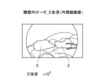
- FIG. 3 is an explanatory diagram schematically showing an image obtained by placing gauze impregnated with a diluted E solution in the abdominal cavity and photographing with an endoscopic camera.
- FIG. 8A is an explanatory diagram showing a near-infrared image of the gauze in FIG. 8A.
- FIG. 2 is an explanatory diagram schematically showing an image obtained by placing gauze impregnated with a diluted N solution in the abdominal cavity and photographing with an endoscopic camera.
- FIG. 9A is an explanatory diagram showing a near-infrared image of the gauze in FIG. 9A.
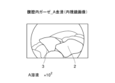
- FIG. 3 is an explanatory diagram schematically showing an image obtained by placing gauze impregnated with a diluted solution of solution A in the abdominal cavity and photographing with an endoscopic camera.
- FIG. 8A is an explanatory diagram showing a near-infrared image of the gauze in FIG. 8A.
- FIG. 2 is an explanatory diagram schematically showing an image obtained by placing gauze impre
- FIG. 10A is an explanatory diagram showing a near-infrared image of the gauze in FIG. 10A.
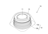
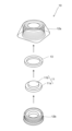
- FIG. 2 is a perspective view showing a configuration example of a CV port. It is a sectional view of the above-mentioned CV port. It is an exploded perspective view of the above-mentioned CV port.
- FIG. 2 is an explanatory diagram schematically showing a state in which rings obtained by molding an epoxy resin are arranged.
- FIG. 14A is an explanatory diagram showing a near-infrared image of each ring in FIG. 14A.
- FIG. 14A is an explanatory diagram showing a near-infrared image of a ring formed by adding a solution having a concentration of ICG four times higher than that of each ring in FIG.
- FIG. 3 is an explanatory diagram schematically showing a state in which the CV port and the comparison port are arranged side by side.
- FIG. 3 is an explanatory diagram showing a near-infrared image of the CV port having an index member molded using G solution.
- FIG. 3 is an explanatory diagram showing a near-infrared image of the CV port having an index member molded using E solution.
- FIG. 3 is an explanatory diagram showing a near-infrared image of the CV port having an index member molded using an N solution.
- FIG. 7 is an explanatory diagram showing a near-infrared image of the CV port having an index member molded using Solution A.
- this embodiment is an illustration for explaining the present invention, and is not intended to limit the present invention to the following content.
- the present invention can be implemented with appropriate modifications within the scope of its gist.
- a numerical range is described as AA to BB, it is assumed that the numerical range includes the lower limit AA and upper limit BB.
- the fluorescent labeling composition according to the present embodiment is a fluorescent labeling composition containing a compound (A) represented by the following formula (1) and a hydroxyl group-containing organic compound (B).
- Compound (A) includes indocyanine green ("ICG”) and its derivatives ("indocyanine green derivative", "ICG derivative”).
- ICG and ICG derivatives may be collectively referred to as “indocyanine green compounds"("ICGcompounds”), etc.
- R 1 and R 2 each independently represent hydrogen, an alkyl group having 1 to 13 carbon atoms, an alkoxy group having 1 to 13 carbon atoms, or a sulfonate group, and p is an integer of 1 to 5. and m and n are each independently an integer from 1 to 12.
- Component (A): indocyanine green compound Compound (A) represented by formula (1) includes indocyanine green (ICG).
- ICG is a compound (CAS No. 3599-32-4) having a structure represented by the following formula (1a), and is a fluorescent organic dye whose excitation light and fluorescence are both in the near-infrared region.
- Formula (1a) is a case where R 1 and R 2 are both hydrogen, p is 2, and m and n are both 4 in formula (1).
- R 1 and R 2 each independently represent hydrogen, an alkyl group having 1 to 13 carbon atoms, an alkoxy group having 1 to 13 carbon atoms, or a sulfonate group; It is preferably an alkyl group having 1 to 8 carbon atoms or an alkoxy group having 1 to 8 carbon atoms, more preferably hydrogen, an alkyl group having 1 to 4 carbon atoms, or an alkoxy group having 1 to 4 carbon atoms. It is even more preferable that there be.
- p is an integer of 1 to 5, preferably 1 to 4, preferably 2 to 3, and more preferably 2.
- n and n are each independently an integer of 1 to 12, preferably 1 to 8, more preferably 2 to 6, even more preferably 3 to 5, and Even more preferably.
- ICG hardly absorbs excitation energy with a wavelength of 600 nm or less, but absorbs excitation energy with a wavelength of 650 to 900 nm and emits fluorescence. For this reason, it is difficult to visually recognize fluorescence when irradiated with visible light, but it is easy to visualize the fluorescence emitted by irradiation with near-infrared light, which is excitation light, by receiving it with a fluorescence microscope or camera. becomes. Therefore, when the composition for fluorescent labeling according to the present embodiment is used for biological fluorescence imaging in blood, the excitation light of ICG is not absorbed by hemoglobin, etc., which has strong absorption in the visible light region of 600 nm or less. .
- ICG is a near-infrared fluorescent organic dye suitable for observing living tissue, that is, observing the conditions of blood vessels, lymph vessels, organs, and the like.
- ICG may exhibit unstable fluorescent coloring, may not be able to obtain sufficient fluorescent intensity, or may become deactivated in a short period of time. Therefore, in clinical practice, conventional ICG is not used in situations that require segment identifiability, such as determining the resection site in surgical operations, and situations that require continuous monitoring over a long period of time. Biofluorescence imaging is insufficient, and there are areas that need improvement.
- the present embodiment by using ICG together with a hydroxyl group-containing organic compound to be described later, stable fluorescent coloring can be obtained and sufficient fluorescent intensity can be obtained, so observation of fluorescently contrasted regions, etc. Excellent partition identifiability can be obtained to the extent that the target structure and the like can be more clearly identified. Furthermore, since the light emission time is long, the observation target can be observed for a long time.
- ICG derivatives that share a basic skeleton with ICG (see formula (1a)), in which R 1 and R 2 are both hydrogen, and p is 1. This also applies to cases where the following is used (excluding the case where m and n are both 4).
- the fluorescent organic dye contains only the compound represented by formula (1) (ICG-based compound). That is, it is preferable that the fluorescent organic dye contains only ICG, an ICG derivative, or both.
- the azo-boron complex compound as disclosed in Patent Document 3 and Patent Document 4 is not substantially contained.
- “not substantially contained” or “not substantially mixed” means that the component is not actively added or mixed, and does not mean that the component is inevitably contained or mixed. It is not excluded.
- the most desirable form of "substantially no content” is the case where the content is zero.
- the hydroxyl group-containing organic compound (B) is an organic compound containing a hydroxyl group (OH group) as a functional group.
- a hydroxyl group (OH group) as a functional group.
- an alcoholic hydroxyl group-containing compound (B1) can be used.
- cellulose (B2) or silk (B3) can be used as the hydroxyl group-containing organic compound (B).
- Silk (B3) is a protein that includes hydroxyl group-containing amino acids such as tyrosine and serine as part of its composition.
- hydroxyl group-containing organic compound (B) since water is an inorganic compound, it is not included in the above-mentioned hydroxyl group-containing organic compound (B). Furthermore, when applying the ICG compound to a resin material described below, a polymer obtained by polymerizing a monomer containing a hydroxyl group, such as an epoxy resin (B4), can be used.
- the alcoholic hydroxyl group-containing compound (B1) is not particularly limited, but aliphatic alcohols are preferred. More preferably, the aliphatic alcohols are aliphatic alcohols having 1 to 10 carbon atoms. The aliphatic alcohol having 1 to 10 carbon atoms preferably has 1 to 5 carbon atoms, even more preferably 1 to 4 carbon atoms.
- alcoholic hydroxyl group-containing compound (B1) examples include, but are not limited to, monoalcohols such as methanol, ethanol, isopropyl alcohol, and propylene glycol; diols such as diethylene glycol; triols such as glycerin; and mannitol. sugar alcohols, etc.
- monoalcohols such as methanol, ethanol, isopropyl alcohol, glycerin, etc.
- diols such as diethylene glycol
- triols such as glycerin
- mannitol. sugar alcohols etc.
- ethanol, isopropyl alcohol, glycerin, etc. are preferred from the viewpoint of cytotoxicity and tissue damage.
- glycerin and the like are more preferable.
- the alcoholic hydroxyl group-containing compound (B1) may be used alone or in combination of two or more.
- the content of compound (A) in the fluorescent labeling composition is not particularly limited, but is preferably 0.0000001 to 10% by mass, more preferably 0.0000001 to 1% by mass, and 0.000001% by mass. It is more preferably from 1% by mass, and even more preferably from 0.000001 to 0.6% by mass.
- concentration quenching phenomenon may occur in which the fluorescence intensity (quantum yield) decreases.
- the concentration quenching phenomenon can be effectively suppressed. As a result, it is possible to further improve the compartment identification when fluorescent light is emitted, and the light emission time can also be made longer (however, the effects of this embodiment are not limited to these).
- the content of the alcoholic hydroxyl group-containing compound (B1) in the fluorescent labeling composition is not particularly limited, but is preferably 90 to 99.9999999% by mass, and preferably 99 to 99.9999999% by mass.
- the content is more preferably from 99 to 99.999999% by mass, even more preferably from 99.4 to 99.999999% by mass.
- the content combination of compound (A) and alcoholic hydroxyl group-containing compound (B1) is such that the content of compound (A) is 0.0000001 to 10% by mass, and the content of alcoholic hydroxyl group-containing compound (B1) is 0.0000001 to 10% by mass. ) is preferably 1 to 90% by mass.
- the content ratio of the alcoholic hydroxyl group-containing compound (B1) to a total of 100 parts by mass of the compound (A) and the alcoholic hydroxyl group-containing compound (B1) is not particularly limited, but it may be contained in a range of 97 to 99.99998 parts by mass.
- the content is preferably from 99.96 to 99.9999 parts by mass, and even more preferably from 99.4 to 99.9997 parts by mass.
- the fluorescent labeling composition according to the present embodiment does not substantially contain DMSO. Similarly, it is preferably substantially free of chloroform. By not substantially containing these organic solvents, the above-mentioned advantages can be further improved. Most preferably, the content of DMSO and chloroform is zero.
- composition for fluorescent labeling may further contain other additive components.
- additive components include components added to contrast media, such as sodium chloride, sodium dihydrogen phosphate, sodium hydrogen phosphate, sodium amidotrizoate, and sodium amidotrizoate meglumine. , iohexol and the like.
- a liquid fluorescent labeling composition is administered into a living body by intraarterial or intravenous injection, and a fluorescence observation device (compatible with excitation light and fluorescence of compound (A)) is used. Contrast imaging can be performed using a camera, etc.). That is, after compound (A) is intravenously injected, the surgical field is irradiated with near-infrared light (excitation light) using a fluorescence observation device, allowing for not only visual observation but also fluorescence observation using near-infrared light. can do. This makes it possible to accurately grasp the state of the surgical field.
- a fluorescent labeling composition For example, by administering a fluorescent labeling composition into the blood, it is possible to determine how far sufficient blood flow has reached. If blood flow is flowing normally, fluorescence will emit light within a relatively short period of time, from a few seconds to a few minutes. That is, if the fluorescent light emission is sufficient, it can be determined that sufficient blood flow is being delivered. Note that the compound (A) becomes tough by binding to blood proteins, and emits fluorescence when irradiated with excitation light.
- a liquid fluorescent labeling composition is injected under the skin near the tumor or in the areola, and then imaged using the above-mentioned fluorescence observation device (camera, etc.). be able to.
- compound (A) is strengthened by binding to plasma proteins in the lymph, and emits fluorescence upon irradiation with excitation light.
- the fluorescent labeling composition When used for angiography, sentinel lymph node identification, etc., as mentioned above, the fluorescent labeling composition should be used in a liquid (25°C, relative The humidity is preferably 50%.
- the composition for fluorescent labeling is a liquid, it may be stored as a highly concentrated solution (for example, a concentrated solution) and diluted at the time of use. The dilution ratio at that time may be set so that the diluent has the above-mentioned suitable concentration and content.
- the concentrated solution and the diluted solution can be prepared, for example, using a vial of distilled water that is attached to the commercially available compound (A).
- composition for fluorescent labeling can also be used clinically as an injection, as described below.
- the injection agent will be described later, but it may be a liquid.
- the injection agent may be in a gel-like or semi-solid form from the viewpoint of imparting a certain viscosity or shape-retaining property.
- at least one component ((D) component) selected from the group consisting of (D) sodium alginate and sodium hyaluronate may be blended.
- the fluorescent labeling composition according to the present embodiment is used as various materials for medical instruments and the like, it is preferable that the fluorescent labeling composition further contains a resin (C).
- a resin (C) for example, by using the fluorescent labeling composition as a molding material for medical devices such as stents, tubes, catheters, clips, fluorescent parts around the septum of subcutaneous implantable ports, filaments for 3D printers, and resin fiber materials. , such medical instruments can be made to emit fluorescence. Note that details of the medical device will be described later.
- the resin (C) in view of the fact that ICG is water-soluble, it is desirable to use a material that does not undergo hydrolysis and has a melting point lower than the melting point of ICG (about 230° C.).
- a material that does not undergo hydrolysis and has a melting point lower than the melting point of ICG (about 230° C.) For example, at least one selected from the group consisting of polyurethane resin, olefin resin, epoxy resin, vinyl chloride resin, fluorine resin, polycarbonate resin, polyamide resin, ABS resin, acrylic resin, and silicone resin.
- it contains seeds.
- These resins are easily available and have high stability, so they are suitable as molding materials for medical instruments and the like. It is also suitable in that it does not adversely affect the fluorescence properties of compound (A).
- a polyurethane resin is a suitable resin.
- the alcoholic hydroxyl group-containing compound (B1) it is better to use a high boiling point organic solvent (e.g. glycerin) than a low boiling point organic solvent to effectively elute compound (A) under high temperature and humidity. It is desirable from the viewpoint of suppressing
- Examples of the olefin resin include polyethylene and polypropylene.
- the epoxy resin (B4) is represented by the following structural formula.
- the epoxy resin (B4) does not necessarily require the alcoholic hydroxyl group-containing compound (B1) because the hydroxyl groups it contains act as a toughening factor for ICG. Therefore, the epoxy resin (B4) has extremely strong fluorescent activity compared to other resins. Examples include epoxy resins made by glycidyl etherification of bisphenol A, bisphenol F, or novolak, etc.; epoxy resins made by adding propylene oxide, ethylene oxide, or polyalkylene glycol to bisphenol A and glycidyl etherification; aliphatic epoxy resins; alicyclic resins; Epoxy resin; examples include polyether epoxy resins. Furthermore, since the epoxy resin (B4) can be coated on metal, it is suitable as a material to be attached to the tips of surgical instruments such as various forceps or scissors.
- vinyl chloride-based resins include vinyl chloride homopolymers, vinyl chloride-vinyl acetate copolymers, vinyl chloride-ethylene copolymers, vinyl chloride-propylene copolymers, vinyl chloride-styrene copolymers, and vinyl chloride-vinyl acetate copolymers.
- vinyl-vinylidene chloride copolymer vinyl chloride-acrylic acid ester copolymer, vinyl chloride-maleic acid ester copolymer, vinyl chloride-methacrylic acid ester copolymer, vinyl chloride-acrylonitrile copolymer, and the like.
- fluororesin examples include polytetrafluoroethylene, tetrafluoroethylene-perfluoroalkyl vinyl ether copolymer, tetrafluoroethylene-hexafluoropropylene copolymer, tetrafluoroethylene-fluoroalkyl vinyl ether-fluoroolefin copolymer, Examples include ethylene-tetrafluoroethylene copolymer and ethylene-trichlorofluoroethylene copolymer.
- polycarbonate resin examples include aromatic polycarbonate resins, aliphatic polycarbonate resins, and aromatic-aliphatic polycarbonate resins containing bisphenol A or the like as a polymerization component.
- polyamide resins examples include polytetramethylene adipamide (nylon 46), polytetramethylene sebaamide (nylon 410), polypentamethylene adipamide (nylon 56), and polypentamethylene sebaamide (nylon 510).
- polycaproamide (nylon 6), polyhexamethylene adipamide (nylon 66), polyhexamethylene sebacamide (nylon 610), polyhexamethylene dodecamide (nylon 612), polydecamethylene adipamide (nylon 106), polydecamethylene sebaamide (nylon 1010), polydecamethylene dodecamide (nylon 1012), polyundecaneamide (nylon 11), polyundecamethylene adipamide (nylon 116), polydodecanamide (nylon 12) ), polyxylene adipamide (nylon XD6), polyxylene sebacamide (nylon (nylon 4T), polypentamethylene terephthalamide (nylon 5T), polyhexamethylene terephthalamide (nylon 6T), polyhexamethylene isophthalamide (nylon 6I), polynonamethylene terephthalamide (nylon 9T), polydecamethylene terephthalamide (nylon 10T), polyundecamethylene terephthalamide
- ABS resins include acrylonitrile butadiene styrene (ABS), acrylonitrile styrene acrylic (ASA), acrylonitrile ethylene styrene (AES), polyethylene chloride acrylonitrile styrene (ACS), and ⁇ -methylstyrene.
- ABS resins include ABS resin, flame-retardant ABS resin (FR-ABS), reinforced ABS resin, and phenylmaleimide-based ABS resin.
- acrylic resins include homopolymers such as polymethyl methacrylate (PMMA) and polyethyl methacrylate; methyl methacrylate-styrene copolymers and methyl methacrylate- ⁇ -methylstyrene copolymers; Examples include copolymers.
- PMMA polymethyl methacrylate
- PEG polyethyl methacrylate
- methyl methacrylate-styrene copolymers methyl methacrylate- ⁇ -methylstyrene copolymers
- Examples include copolymers.
- silicone resin examples include methyl silicone resin, methylphenyl silicone resin, phenyl silicone resin, epoxy-modified silicone resin, polyester-modified silicone resin, and acrylic-modified silicone resin.
- acetal resin may undergo hydrolysis when mixed with ICG, and may emit harmful substances such as formaldehyde. For this reason, it is desirable that the resin (C) does not contain an acetal resin.
- the resin (C) may be used alone or in combination of two or more.
- the content of the resin (C) in the fluorescent labeling composition is not particularly limited, but is preferably 80 to 99.99998% by mass, more preferably 85 to 99.9999% by mass, and 90 to 99% by mass. More preferably, it is .9997% by mass.
- the content of the resin is not particularly limited, but is preferably 80 to 99.99998% by mass, more preferably 85 to 99.9999% by mass, and 90 to 99% by mass. More preferably, it is .9997% by mass.
- the state of the composition for fluorescent labeling at 25° C. and 50% relative humidity is preferably solid or semi-solid.
- a semi-solid state is different from a liquid state and means that it has a shape retention property like a paste state or the like.
- the above-mentioned resin (C) may be blended, or the alcoholic hydroxyl group-containing compound (B1) in a solid or semi-solid state may be blended. You may.
- the alcoholic hydroxyl group-containing compound (B1) is preferably glycerin or the like. Further, other solid or semi-solid components may also be blended.
- the method for producing a composition for fluorescent labeling of the present embodiment includes a mixing step of mixing the above-described compound (A) and a hydroxyl group-containing organic compound (B).
- the hydroxyl group-containing organic compound (B) the above-mentioned alcoholic hydroxyl group-containing compound (B1) can be used.
- the mixing method in the mixing step is not particularly limited, and any known method can be selected.
- suitable conditions can be adopted as appropriate.
- the mixing step it is preferable to obtain a composition for fluorescent labeling containing 0.0000001 to 10% by mass of the compound (A) and 1 to 90% by mass of the alcoholic hydroxyl group-containing compound (B1).
- the mixing process does not necessarily have to be carried out in one step.
- a step of obtaining a highly concentrated concentrate may be performed, and then a step of diluting the concentrated liquid to the above concentration range at the time of use or the like may be performed. That is, the dilution concentration during use is preferably within the above-mentioned concentration range.
- a step of heating the mixture may be performed.
- the above-described composition for fluorescent labeling can be suitably used as a fluorescent probe.
- it can be used as an organic compound type fluorescent probe derived from compound (A).
- the excitation light is not absorbed by hemoglobin or the like, so the excitation light can reach deep inside the living tissue and its state can be visually recognized and observed. can do.
- fluorescence it has excellent compartment identification and the composition itself has a long lifespan, so it continues to emit light for a long time. Because of these advantages, the fluorescent labeling composition of this embodiment is suitable as a fluorescent probe.
- the fluorescent labeling composition described above can be suitably used as an injection.
- a preferred aspect of the injection of this embodiment is a labeling injection for labeling an object present on a mucous membrane or skin, and is an injection containing the above-described fluorescent labeling composition.
- the above-mentioned injection agent is injected under the mucous membrane or skin where the target object is located, and can be labeled by being irradiated with excitation light of compound (A).
- injections can be used for various local injections under the mucous membrane or skin of a site to be excised, such as a tumor.
- an injection agent is injected under the mucous membrane or skin around the lesion and is caused to emit fluorescence by irradiating it with excitation light. .
- the planned resection line of the lesion (the boundary between the side to be left and the side to be excised) can be accurately identified. Further, by using both visual findings and fluorescence observation by a doctor, a more appropriate planned cutting line can be determined.
- the alcoholic hydroxyl group-containing compound (B1) as the hydroxyl group-containing organic compound (B) is preferably glycerin or mannitol from the viewpoint of safety to the human body. These may be used alone or in combination of two or more.
- the injection according to this embodiment can also contain at least one of sodium alginate and sodium hyaluronate as component (D).
- This component (D) can also function as a viscosity enhancer.
- the injection agent can be injected into the submucosal layer or the subcutaneous layer near the lesion, for example, and the injected area can be expanded so as to rise.
- the above-mentioned fluorescence observation device such as a camera
- the position of the lesion can be accurately grasped, and the scheduled resection line of the lesion can be identified more accurately.
- the content of the component (D) in the injection agent according to the present embodiment is not particularly limited, but the total content of the components (D) is preferably 0.01 to 10% by mass, and 0.05 to 5% by mass. %, even more preferably 0.05 to 3% by mass, even more preferably 0.1 to 1% by mass. However, if sufficient viscosity and local localization are obtained, it is effective even if the injection does not contain component (D) at all.
- the fluorescent labeling composition described above can be suitably used as a syringe filling.
- the syringe filling is configured by filling a syringe (syringe barrel) with the fluorescent labeling composition of this embodiment in advance.
- the syringe filling is also called a prefilled syringe or the like.
- the material and size and shape of the syringe are not particularly limited, and suitable conditions can be selected depending on the application.
- the syringe may be made of glass or resin, for example.
- the tube of a local injection needle for submucosal injection may also be filled with the fluorescent labeling composition, and the local injection needle may be connected to a prefilled syringe.
- the compound (A), the hydroxyl group-containing organic compound (B), other solvents, and additive components are contained from the viewpoint of suppressing the concentration quenching phenomenon and ensuring sufficient fluorescence emission intensity and emission time. It is important to appropriately adjust the amount and content ratio. However, it is complicated to mix these medicinal solutions at the time of surgery. By filling a syringe (+local injection needle tube) with a fluorescent labeling composition prepared in advance at an accurate content ratio, such complicated work can be omitted at the time of surgery.
- a syringe is filled with a concentrated solution in which the content ratio of the compound (A) and the alcoholic hydroxyl group-containing compound (B1) as the hydroxyl group-containing organic compound (B) is within the above-mentioned preferred range, and at the time of use, It can be used after being diluted with physiological saline or water for injection.
- the syringe filling according to the present embodiment is not limited to a structure in which the syringe is filled with a concentrated solution of the fluorescent labeling composition.
- a syringe filling may be constructed by filling a syringe with the fluorescent labeling composition as it is at an injectable concentration (diluted solution).
- a medical device can be produced using the above-described composition for fluorescent labeling as a molding material.
- Such medical devices include stents, tubes, catheters, clips, fluorescent parts around the septum of subcutaneous implantable ports, filaments for 3D printers, resin fiber materials (e.g. gauze threads, sutures, etc.), Other examples include surgical instruments such as various forceps or scissors whose tips are coated or the like.
- medical devices to which the fluorescent labeling composition is applied are particularly stents, tubes, catheters, fluorescent parts around the septum of subcutaneous implantable ports, filaments for 3D printers, resin fiber materials (e.g. The material is preferably one selected from the group consisting of medical gauze, sponges, tuppels, cotton balls, tampons, silk threads, sponges, etc.) and surgical instruments such as various forceps or scissors.
- a fluorescent labeling composition is included in the material constituting the stent.
- the stent can be caused to emit fluorescence by placing the stent in a living body and irradiating the stent with near-infrared rays, which is excitation light of compound (A).
- the stent is, for example, a bile duct stent or a ureteral stent
- the location of the stent can be accurately determined by the fluorescent light emitted from the stent. This can reduce the risk of accidentally damaging the bile duct or ureter during surgery.
- a fluorescent labeling composition is included in the material constituting the tube.
- the tube By placing the tube in a living body and irradiating the tube with near-infrared rays, which is excitation light of compound (A), the tube can be caused to emit fluorescence.
- near-infrared rays which is excitation light of compound (A)
- the tube can be caused to emit fluorescence.
- the placement position of the tube can be accurately determined by fluorescence emission, so even when performing laparoscopic surgery, the site of intestinal obstruction, etc. can be identified more accurately.
- a fluorescent labeling composition is included in the material constituting the catheter.
- the catheter can be caused to emit fluorescence by placing the catheter in a living body and irradiating the catheter with near-infrared rays, which is excitation light of compound (A).
- near-infrared rays which is excitation light of compound (A).
- the placement position of the catheter can be accurately ascertained by fluorescence emission, so it is possible to avoid the risk of accidentally damaging the ureter during surgery.
- a subcutaneous implantable port in which the material constituting the septum or housing portion contains a fluorescent labeling composition does not contain a drug.
- the resin will come into direct contact with the patient's subcutaneous tissue for a long period of time, which is unfavorable from a medical safety standpoint.
- a septum that is repeatedly punctured with a needle has the problem of coring, where the material is gradually worn away, and it is undesirable to include drugs, including concerns about decreased durability.
- the housing part is impregnated with a drug to cause fluorescence to develop, there is a concern that the emission range will be too wide and the central septum part will not be fluorescently negative.
- the fluorescent labeling composition is built into the housing around the septum (if it is present inside the outer surface of the housing), the position of the septum can be recognized without the light-emitting part coming into contact with the patient's subcutaneous tissue. becomes possible.
- the fluorescent labeling composition may be in the form of a ring or a collection of spots as long as it is arranged around the septum.
- the method for manufacturing the medical device of this embodiment described above is not particularly limited, but any known method can be adopted.
- a manufacturing method including a step of injection molding the above-described composition for fluorescent labeling using a mold or the like can be adopted.
- the medical device may be manufactured by extrusion molding, compression molding, blow molding, calendar molding, inflation molding, thermoforming, or the like.
- a fluorescent labeling composition is included in the fiber material.
- the resinous fiber material include gauze threads, surgical suture threads, and the like.
- gauze as in Patent Document 4, a resin fiber material impregnated with a fluorescent labeling composition is woven into a part of the cotton cloth constituting the gauze, and the excitation light of compound (A) is used to It is conceivable that by irradiating the gauze with infrared rays, the fiber material forming a part of the gauze can be caused to emit fluorescence.
- the luminescence intensity may be insufficient to be used as an indicator for search or surgical operation in the event of dissipation.
- the blending ratio of the resin fiber material is increased, the water absorbency will decrease and there is a risk that the gauze will not be able to fulfill its original function. For this reason, it is desirable that the entire cotton fabric constituting the gauze contain the fluorescent labeling composition.
- the suture when the suture contains a composition for fluorescent labeling, the suture emits fluorescence by irradiating the suture with near-infrared rays, which is excitation light of compound (A).
- the drug-containing fibers come into semi-permanent contact with the patient's tissue, which is unfavorable in terms of medical safety.
- the needle in the method in which the needle is fluorescently colored, the needle is removed from the body, but resin adheres to the needle, which may impair its original sharpness.
- an epoxy resin containing compound (A) for example, is used as the adhesive that connects the needle and thread in a "needle thread" in which a needle is attached to the tip of the suture thread, the above-mentioned problems can be solved. It becomes possible to find a lost needle without causing any trouble.
- such a resin fiber material can be suitably used not only for the purpose of use in the medical field (medical use) but also as a luminous fiber, luminous material, etc. in a wide range of fields. Further, since the fiber material is made of resin, the compound (A) can be uniformly dispersed and blended into the resin, and therefore the entire material can uniformly emit fluorescence.
- the composition for fluorescent labeling of this embodiment (for example, compound (A) + hydroxyl group-containing organic compound (B)) may be kneaded with resin and thread-spun.
- compound (A) alone may be kneaded with a resin and then thread-spun.
- the medical fiber material of this embodiment includes the above-mentioned compound (A) and a fiber material containing a hydroxyl group-containing organic compound (B), and can emit light when irradiated with excitation light of the compound (A). It is.
- the medical fiber material is irradiated with the excitation light of the compound (A)
- fluorescence is obtained from the medical fiber material, and the fluorescence has excellent zone identification and a long luminescence time.
- the hydroxyl group-containing organic compound (B) contained in the fiber material preferably contains cellulose (B2), and also consists of animal protein such as silk (B3). May contain fiber.
- Such medical fiber materials include, but are not particularly limited to, medical gauze, sponges, tuppels, cotton balls, tampons, silk threads, and fiber materials constituting these.
- medical gauze sponges, tuppels, cotton balls, tampons, silk threads, and fiber materials constituting these.
- the medical fiber material according to the present embodiment when used as medical gauze, it can contribute to preventing gauze from being left behind in the body during surgery in clinical practice such as surgery. An example of how to use such medical gauze will be described below.
- X-ray gauze contrast threads appear thin and white in X-ray images, so if they overlap with bones, they are difficult to see and may be overlooked even when looking at X-ray images.
- the presence of the entire gauze can be clearly confirmed by emitting green or blue fluorescence, so the gauze can be easily confirmed even though it is a simple method.
- near-infrared light is used instead of X-rays, the exposure dose to patients and staff can be reduced, resulting in high safety.
- the medical gauze according to this embodiment can achieve excellent compartment identification and long luminescence time is that the compound (A) and cellulose (B2), which is the hydroxyl group-containing organic compound (B) contained in the gauze, are It is thought that this is because the hydroxyl group is strongly bonded with the hydrogen bond and takes a stable form (however, the effects of this embodiment are not limited thereto). Therefore, in surgery, by placing gauze in advance at the target ablation point and using the fluorescence of the gauze as an indicator, the operation can be carried out efficiently.
- the gauze used only needs to contain a hydroxyl group-containing organic compound (B) (for example, cellulose (B2)), and other materials, dimensions, and shapes are not particularly limited.
- B hydroxyl group-containing organic compound
- the gauze used may be angular gauze used as surgical gauze (operating gauze), etc., or may be cut gauze, folded gauze, wide gauze, etc. that is applied to the wound or the injured area.
- the gauze used may be sterilized using ethylene oxide gas (EOG), an autoclave, or the like.
- EOG ethylene oxide gas
- the amount of compound (A) added is not particularly limited, it is preferable to control the amount added to a certain level, for example, from the viewpoint of accurately grasping the amount of bleeding during a surgical operation.
- the amount of compound (A) added per m 2 of gauze is preferably 0.001 to 10 g, more preferably 0.01 to 5 g, and even more preferably 0.1 to 3 g. . Further, even if blood adheres to the gauze, the visibility of the fluorescence is not inhibited, and the binding of proteins in the blood to ICG further enhances the luminescence.
- the medical fiber material according to this embodiment may further contain the above-mentioned alcoholic hydroxyl group-containing compound (B1). Further, the medical fiber material may contain other additive components including water, instead of or in addition to the alcoholic hydroxyl group-containing compound (B1). .
- the medical fiber material according to this embodiment may further contain a mordant.
- a mordant By using a mordant, the compound (A) can be fixed to the gauze together with the dye.
- the mordant alum, iron oxide, etc. can be used.
- the medical fiber material according to this embodiment is used as a medical gauze, but the medical fiber material according to this embodiment is not limited to such usage.
- medical fiber materials when medical fiber materials are used as sponges, tuppels, cotton balls, tampons, silk thread (with needles), etc., or as the fiber materials that make up these materials, they emit fluorescence when used, similar to medical gauze. can be done.
- the above-mentioned silk thread (with a needle) may be used, for example, as a target during a second-stage surgery. If the silk thread (with needle) emits fluorescence, the target can be easily recognized, which is very useful when performing such a two-stage surgery.
- the method for manufacturing a medical fiber material according to this embodiment includes an impregnation step and a mordant step.
- a fiber material containing a hydroxyl group-containing organic compound (B) is impregnated with a solution containing the above-described compound (A).
- the mordant step the compound (A) is fixed to the fiber material using a mordant.
- the fiber material is not particularly limited as long as it contains the hydroxyl group-containing organic compound (B) and can be impregnated with a solution containing the compound (A).
- the hydroxyl group-containing organic compound (B) preferably contains cellulose (B2) or silk (B3).
- silk (B3) is a protein having a hydroxyl group-containing amino acid as a constituent component.
- fiber materials include medical gauze, sponges, tuppels, cotton balls, tampons, silk threads (with needles), and fiber materials constituting these. For example, medical gauze, sponges, tuppels, cotton balls, tampons, silk threads (with needles), etc.
- impregnated with the above solution may be directly impregnated with the above solution, or medical gauze, sponges, tuppels, cotton balls, tampons, (with needles), etc.
- a fiber material constituting silk thread or the like may be impregnated with the above solution.
- fiber materials commonly used in the medical field and other fields can also be used.
- the above impregnation step may be performed by spraying.
- impregnation here refers to impregnating the fiber material with the above solution, but it may also be impregnated by immersing the fiber material in the solution, or by spraying the solution onto the fiber material. It may be impregnated by.
- the impregnation step when impregnating a fiber material such as gauze with the solution, the impregnation step includes at least the compound (A) and the alcoholic hydroxyl group-containing compound (B1) as the hydroxyl group-containing organic compound (B). It may also be impregnated with a solution containing it. In this case, the alcoholic hydroxyl group-containing compound (B1) can be used as a solvent for the compound (A).
- Impregnation conditions are not particularly limited, and suitable conditions can be selected as appropriate in consideration of the material, size, shape, etc. of the fiber material.
- the impregnation time is preferably 1 minute to 3 days at room temperature and humidity, and it is preferable to shield from light during impregnation. Note that, as described above, impregnation may be performed by spraying.
- the solution used in the method for producing a medical fiber material may be a composition containing the compound (A), the alcoholic hydroxyl group-containing compound (B1), and water. Note that the above solution does not necessarily need to contain the alcoholic hydroxyl group-containing compound (B1). Therefore, the solution may have a structure containing only compound (A) and water.
- alcoholic hydroxyl group-containing compound (B1) for example, a low boiling point or volatile alcoholic hydroxyl group-containing compound such as methanol, ethanol, isopropyl alcohol, etc. may be used, or a high boiling point alcoholic hydroxyl group-containing compound such as glycerin. Compounds may also be used.
- the compound (A) when gauze is impregnated with the fluorescent labeling composition, the compound (A) is supported on the gauze, and then the alcohol The hydroxyl group-containing compound (B1) is volatilized or removed, and the compound (A) is supported on the gauze.
- gauze is impregnated with the above solution to support the compound (A) on the gauze, and then the alcoholic hydroxyl group-containing compound (B1 ) is supported on the gauze together with compound (A) without being removed.
- alcoholic hydroxyl group-containing compounds (B1) a low boiling point or volatile alcoholic hydroxyl group-containing compound is preferable, ethanol and isopropyl alcohol are more preferable, and ethanol is preferable. is even more preferable.
- a component as the alcoholic hydroxyl group-containing compound (B1) it is possible to use a simple and economical method, and to achieve a state in which only the compound (A) is supported on the medical gauze. I can do it.
- the mordant step using a mordant includes, for example, a step of dyeing the compound (A) onto gauze using the mordant.
- the dyeing step may be pre-mordanting, post-mordanting, or simultaneous mordanting, but post-mordanting is preferable from the viewpoint of dyeing the compound (A) onto the gauze.
- the mordant those mentioned above can be used. Mordant conditions are not particularly limited.
- a protein treatment step may be performed in which the fiber material is impregnated with a protein preparation.
- the compound (A) can be fixed to the gauze together with the dye.
- the protein preparation milk, soy milk, skim milk powder, etc. can be used.
- Sterilization conditions are not particularly limited, and methods known as methods for sterilizing medical fiber materials such as medical gauze can be employed.
- Instruments may be prepared by coating the tips of surgical instruments such as various forceps or scissors with, for example, an epoxy resin containing a fluorescent labeling composition. In this case, the operation can be performed while visually checking the tip of the instrument hidden behind the organ, etc., thereby improving the safety of the surgery.
- the composition for fluorescent labeling according to the present embodiment has at least excellent compartment discrimination to the extent that the structure of the observation target can be identified more accurately, has a long luminescence time, and has a long luminescence time. can be observed over a long period of time, and furthermore, it places less burden on living organisms and is highly economical.
- the excitation light is not absorbed by substances in living tissues such as hemoglobin, and the light can reach deep into living tissues, allowing observation of the conditions of blood vessels, lymph vessels, organs, etc. There is also the advantage that it can be done.
- composition for fluorescent labeling is also useful as a fluorescent probe, injection agent, syringe filler, medical instrument, medical fiber material, etc., and can exhibit the above-mentioned advantages.
- the method for producing the composition for fluorescent labeling and the medical fiber material has advantages as a production method because easily available materials or components can be used and production can be performed by a simple method.
- the composition for fluorescent labeling, the fluorescent probe, the injection agent, the syringe filling, the medical device, and the medical fiber material according to the present embodiment have the various advantages described above, and therefore, the composition is an ICG-based compound (compound (A)). It can be suitably used for biofluorescence imaging using. For example, in the medical field, it can be applied to angiography, tumor fluorescence imaging, identification of regional lymph nodes including sentinel lymph nodes, marking of surgical operation targets, marking of organs to avoid damage, prevention of remaining body parts, prevention of dissipation, etc. I can do it. Furthermore, it is expected to be applied in fields other than medical settings, such as basic medical research, life science, regenerative medicine, various diagnostics, architectural engineering, and entertainment. That is, the composition for fluorescent labeling of this embodiment is not limited to medical use, and can be expected to be applied to a wide range of other uses.
- the fluorescent marking composition described in this embodiment may be applied to the building. By kneading or coating the material, it is possible to identify a specific location (location where the fluorescent labeling composition is present) without the user knowing. Furthermore, if a "glowing contact lens" is made using the fluorescent labeling composition described in this embodiment, the performer who wears the "luminous contact lens" on his or her eyes will not feel the fluorescence and only the viewer will be able to see the eye. Can recognize light (emission from contact lenses). In other words, the fluorescent labeling composition of this embodiment can be expected to be applied to theatrical productions.
- PP polypropylene
- PVC polyvinyl chloride
- LDPE low-density polyethylene
- EVA ethylene-vinyl acetate copolymer resin
- TPU thermoplastic polyurethane
- phr is an abbreviation for per hundred resin, and is a unit that expresses the ratio of pigment blended when the weight of the resin is 100. For example, if Ag pigment is contained in 100 g of resin, the ratio of the pigment can be said to be A (phr).
- the kneading procedure is as follows. (Step 1: Pre-kneading) The resin was placed in a preheated mixer and kneaded until plasticized. As the mixer, Labo Plast Mill 4M150 manufactured by Toyo Seiki Seisakusho Co., Ltd. was used. Note that "Laboplasto Mill” is a registered trademark of Toyo Seiki Seisakusho Co., Ltd. This process was performed for each resin prepared in advance. Kneading was performed for 5 minutes at a temperature set for each resin.
- the above kneading temperatures are: polypropylene: 170°C, polyvinyl chloride: 150°C, low density polyethylene: 140°C, ethylene/vinyl acetate copolymer resin: 140°C, thermoplastic polyurethane: 150°C. there were.
- both kneading temperatures are lower than the melting point (230° C.) of ICG.
- Step 2 Pigment kneading
- resin + pigment After confirming that the resin was sufficiently plasticized in step 1, pigment was added and kneaded.
- Step 3 Compression molding
- the above sample was cut into pieces using scissors. Then, the cut sample was sandwiched between a pair of heat-resistant polyimide films, and the sample-containing film was placed between a pair of metal plates (for example, stainless steel plates). Subsequently, a pair of metal plates containing a sample-containing film were placed between a pair of spacers. Thereafter, the pair of spacers were pressed toward each other, and the sample was melted and compressed for 1 minute to the desired thickness to form a sheet.
- the compression molding temperature was the same as in steps 1 and 2. After forming, the pair of metal plates were placed on a mounting table and left to cool at room temperature with a weight placed on them. Note that two types of sheet thicknesses were obtained: 1 mm thick (110 mm long x 110 mm wide) and 0.5 mm thick (125 mm long x 125 mm wide).
- G solution is a solution in which 25 mg of ICG is mixed and dissolved in 10 ml of glycerol.
- Solution E is a solution in which 25 mg of ICG is mixed and dissolved in 10 ml of ethanol.
- the N solution is a solution in which 25 mg of ICG is mixed and dissolved in 10 ml of distilled water.
- Solution A is a solution in which 25 mg of ICG is mixed and dissolved in 10 ml of 5% BSA solution. Note that BSA is bovine serum albumin. Distilled water did not contain ICG and was prepared for comparison with a stock solution containing ICG.
- FIG. 1A schematically shows a state in which each stock solution is placed in containers (transparent containers) and arranged side by side.
- the containers are lined up in this order from the left: G solution, E solution, N solution, A solution, and distilled water.
- An ICG standard card 1 is placed on the right side of the container containing distilled water.
- the ICG reference card 1 has a light emitting area 1a.
- the light emitting region 1a is a region containing ICG, and emits fluorescence when irradiated with excitation light (near infrared light).
- the presence or absence of light emission during irradiation with near-infrared light and the brightness of the light-emitting portion are compared and evaluated relatively, using the light-emission brightness of the light-emitting area 1a of the ICG reference card 1 as a reference. That is, the ICG reference card 1 is used for relative comparison and evaluation of luminance.
- Figure 1B shows an image (hereinafter also referred to as a near-infrared image) obtained by irradiating each container with near-infrared light and photographing each container with a near-infrared camera (Olympus VISERAELITE II). . From the figure, it can be seen that in the undiluted state, the luminance of the G solution and the E solution is high.
- a near-infrared image obtained by irradiating each container with near-infrared light and photographing each container with a near-infrared camera (Olympus VISERAELITE II).
- diluted solutions were prepared by diluting each stock solution 5 times, 10 times ( ⁇ 10 1 ), 100 times ( ⁇ 10 2 ), 1000 times ( ⁇ 10 3 ), and 10000 times ( ⁇ 10 4 ). Note that dilution was performed here using the solvent of each stock solution.
- Figure 2 shows near-infrared images obtained for the G solution. Note that in FIG. 2, for convenience, the container containing the 5-fold diluted solution is omitted (the same applies to FIGS. 3 to 5). From FIG. 2, it can be seen that with the G solution, good (high) luminescence brightness can be obtained regardless of the dilution ratio.
- Figure 3 shows a near-infrared image obtained for the E solution. From the same figure, it can be seen that, similarly to the G solution, good (high) luminescence brightness can be obtained with the E solution regardless of the dilution ratio.
- Figure 4 shows near-infrared images obtained for the N solution. From the figure, it can be seen that with the N solution, high emission brightness is obtained when diluted 1000 times, but the emission brightness is low at other dilution ratios.
- Figure 5 shows a near-infrared image obtained for solution A. From the figure, it can be seen that in solution A, high luminescence brightness is obtained from 10-fold dilution to 10000-fold dilution, and in particular, higher luminescence luminance is obtained at 100-fold dilution and 1000-fold dilution.
- a dilution solution with a desired dilution ratio here, distilled water was used, but the solvent of each stock solution may also be used
- a near-infrared image was obtained by impregnating gauze with the diluted solution.
- the gauze Sterase (sterilized, 5 cm x 5 cm) manufactured by Hakujuji Co., Ltd. was used. Note that "Stellase” is a registered trademark of Hakujuji Co., Ltd.
- FIG. 6A schematically shows gauze impregnated with 5-fold, 10-fold, 100-fold, and 1000-fold dilutions of G solution, E solution, N solution, and A solution, respectively, arranged vertically and horizontally. It is shown in In FIG. 6A, gauze impregnated with G solution, E solution, N solution, and A solution are arranged from the top to the bottom, and from the left to the right, 5 times, 10 times, 100 times, 100 times. Lay out each piece of gauze impregnated with twice the amount of each diluted solution. Further, in FIG. 6A, the ICG reference card 1 is placed on the right side of the gauze impregnated with a 1000-fold diluted solution, and the untreated gauze 2 is placed above the ICG reference card 1. The untreated gauze 2 is simply gauze that has not been impregnated.
- FIG. 6B shows a near-infrared image obtained when each gauze in FIG. 6A is irradiated with near-infrared light. From the same figure, it was found that high luminescence brightness was obtained in gauze impregnated with a diluted solution of 10 times to 1000 times for each of the G solution, E solution, N solution, and A solution. In particular, it was found that gauze impregnated with a 100-fold diluted solution provided the highest luminescence brightness.
- FIG. 7A, FIG. 8A, FIG. 9A, and FIG. 10A schematically show images taken with an endoscopic camera when untreated gauze 2 and treated gauze 3 are placed in the abdominal cavity of a pig.
- the treated gauze 3 in FIG. 7A gauze impregnated with a diluted solution obtained by diluting the G solution 100 times was used.
- the treated gauze 3 in FIG. 8A gauze impregnated with a 100-fold dilution of solution E was used.
- the treated gauze 3 in FIG. 9A gauze impregnated with a 100-fold diluted N solution was used.
- gauze impregnated with a 100-fold dilution of solution A was used.
- FIG. 7B, FIG. 8B, FIG. 9B, and FIG. 10B show near-infrared images obtained when near-infrared light is irradiated to each gauze of FIG. 7A, FIG. 8A, FIG. 9A, and FIG. 10A. From these figures, it was found that each treated gauze 3 emitted light with high luminescence intensity when irradiated with near-infrared light in the abdominal cavity.
- FIG. 11 is a perspective view showing a configuration example of a CV port (central venous port) 10 as a subcutaneously implanted port.
- FIG. 12 is a cross-sectional view of the CV port 10 of FIG. 10.
- FIG. 13 is an exploded perspective view of the CV port 10 of FIG. 10. Note that in FIG. 11, the outer shape of the housing portion 12 is shown by broken lines in order to clarify the internal configuration of the CV port 10.
- the CV port 10 includes a septum 11, a housing portion 12, and an indicator member 13.
- the septum 11 is made of, for example, soft silicone rubber.
- the septum 11 integrally includes a large diameter portion 11a and a small diameter portion 11b.
- the small diameter portion 11b has a smaller diameter than the large diameter portion 11a.
- the small diameter portion 11b is located above the large diameter portion 11a coaxially with the large diameter portion 11a.
- a Huber needle for injecting a medicinal solution is inserted into the septum 11 (for example, the small diameter portion 11b).
- the housing part 12 is a cover that holds the septum 11, and holds the septum 11 so that the upper surface of the septum 11 (for example, the small diameter part 11b) is exposed.
- a housing part 12 has an outer housing 12a and an inner housing 12b.
- the outer housing 12a is made of, for example, transparent acrylic resin.
- CV port 10 When CV port 10 is implanted subcutaneously in a patient, a portion of the outer surface (eg, the top surface) of outer housing 12a contacts the patient's skin.
- a thread groove is formed on the inner peripheral surface of the outer housing 12a.
- the inner housing 12b is a back cover located inside the outer housing 12a.
- a thread is formed on the outer peripheral surface of the inner housing 12b.
- the inner housing 12b is fixed to the outer housing 12a by screwing the inner housing 12b inside the outer housing 12a while engaging the threads with the thread grooves.
- a recess 12b1 is formed in the upper part of the inner housing 12b.
- the large diameter portion 11a of the septum 11 is inserted into the recess 12b1 and is sandwiched between the inner housing 12b and the outer housing 12a from above and below.
- a liquid injection chamber 12b2 that accommodates the above-mentioned chemical liquid is formed in the inner housing 12b.
- the liquid injection chamber 12b2 is formed to have a smaller diameter than the recess 12b1, and is located below the recess 12b1.
- the medicinal solution injected into the liquid injection chamber 12b2 through the Huber needle inserted into the septum 11 is introduced into a blood vessel or the like via a catheter (not shown) communicating with the liquid injection chamber 12b2.
- the indicator member 13 is arranged inside the housing part 12 and outside the septum 11. More specifically, the indicator member 13 is located inside the outer shape of the housing portion 12 (particularly the outer housing 12a). Further, the indicator member 13 is arranged on the upper surface of the large diameter part 11a of the septum 11, and is arranged radially apart from the small diameter part 11b (see especially FIG. 12). The indicator member 13 is covered with an outer housing 12a. Therefore, a portion of the outer housing 12a is located between the index member 13 and the small diameter portion 11b.
- the indicator member 13 is a ring-shaped member surrounding the septum 11 (particularly the small diameter portion 11b).
- the shape of the index member 13 is not limited to a ring shape (circular in plan view), but may be other shapes such as a rectangular shape or an elliptical shape.
- the indicator members 13 do not necessarily need to be formed continuously in the circumferential direction, and may be arranged in plurality at intervals in the circumferential direction, for example.
- the indicator member 13 has the fluorescent labeling composition of this embodiment described above. Specifically, the indicator member 13 is constructed by kneading the above-mentioned pigment (ICG+solvent) as a composition for fluorescent labeling into a resin, and molding the kneaded resin into, for example, a ring shape.
- the indicator member 13 includes a fluorescent labeling composition
- near-infrared light irradiation targets not the septum 11 itself but the portion (indicator member 13) inside the housing portion 12 that does not come into direct contact with the patient's subcutaneous tissue.
- the septum 11 can be recognized by emitting fluorescence. Therefore, there is no problem of the resin containing the drug being in direct contact with the patient's subcutaneous tissue for a long period of time, and safety can be reliably improved.
- the indicator member 13 has a shape (for example, a ring shape) that surrounds the septum 11 in plan view, it is possible to easily recognize that the septum 11 is present in the area surrounded by the indicator member 13. Therefore, it becomes easy to puncture the Huber needle using the above region as an index.
- FIG. 14A shows rings (corresponding to index members 13) formed by mixing G solution, E solution, N solution, and A solution with epoxy resin at a ratio of 1 phr, 3 phr, 5 phr, and 10 phr, respectively, and arranging them vertically and horizontally.
- This diagram schematically shows the state in which the In FIG. 14A, rings formed by mixing G solution, E solution, N solution, and A solution with epoxy resin are arranged from the top to the bottom.
- the ICG reference card 1 is placed at the left end, and the negative control 4 is placed above the ICG reference card 1.
- Negative control 4 is used for comparison with each ring and consists only of epoxy resin without ICG.
- rings are further arranged to the right of the ICG reference card 1 and the negative control 4 in the order of ratios 1 phr, 3 phr, 5 phr, and 10 phr from left to right.
- FIG. 14B shows a near-infrared image obtained when each ring (ICG1v ring) in FIG. 14A is irradiated with near-infrared light.
- the ICG1v ring is a ring formed by mixing the following G solution, E solution, N solution, and A solution with an epoxy resin. That is, the G solution is a solution in which 25 mg of ICG is mixed and dissolved in 10 ml of glycerol.
- Solution E is a solution in which 25 mg of ICG is mixed and dissolved in 10 ml of ethanol.
- the N solution is a solution in which 25 mg of ICG is mixed and dissolved in 10 ml of distilled water.
- Solution A is a solution in which 25 mg of ICG is mixed and dissolved in 10 ml of 5% BSA solution. From the figure, it was found that rings molded using any of the G solution, E solution, N solution, and A solution had luminance equal to or higher than that of the ICG standard card. In particular, it was found that higher luminance can be obtained with a ring of 3 phr or more.
- FIG. 15 shows a near-infrared image obtained when each ring (ICG1v ring) in FIG. 14A is replaced with an ICG4v ring and each ring is irradiated with near-infrared light.
- the ICG4v ring is a ring formed by mixing the following G solution, E solution, N solution, and A solution with an epoxy resin. That is, the G solution is a solution in which 100 mg of ICG is mixed and dissolved in 10 ml of glycerol.
- Solution E is a solution in which 100 mg of ICG is mixed and dissolved in 10 ml of ethanol.
- the N solution is a solution in which 100 mg of ICG is mixed and dissolved in 10 ml of distilled water.
- Solution A is a solution in which 100 mg of ICG is mixed and dissolved in 10 ml of 5% BSA solution. It was found that high luminance was obtained for all ICG4v rings from 1 phr to 10 phr, regardless of whether they were molded using G solution, E solution, N solution, or A solution.
- FIG. 16A schematically shows a state in which the CV port 10 including the indicator member 13 and the comparison port 10A not including the indicator member 13 are arranged vertically.
- the negative control 4 is placed on the left side of the CV port 10.
- the ICG reference card 1 is placed below the negative control 4 (to the left of the comparison port 10A).
- FIG. 16B is a near-infrared image obtained when near-infrared light is irradiated to the CV port 10 and comparison port 10A in FIG. This shows a near-infrared image when mixed with epoxy resin and molded.
- 17 to 19 are near-infrared images when the index member 13 of the CV port 10 is molded by mixing epoxy resin with the following ratios: 10 phr of E solution, 10 phr of N solution, and 10 phr of A solution. shows.
- the fluorescent labeling composition, fluorescent probe, injection agent, syringe filling, medical device, medical textile material, method for manufacturing the fluorescent labeling composition, and method for manufacturing the medical textile material described in this embodiment above are as follows: , can be expressed as described in the appendix below.
- composition for fluorescent labeling is A compound (A) represented by the following formula (1), Contains a hydroxyl group-containing organic compound (B).
- R 1 and R 2 each independently represent hydrogen, an alkyl group having 1 to 13 carbon atoms, an alkoxy group having 1 to 13 carbon atoms, or a sulfonate group, and p is an integer of 1 to 5. and m and n are each independently an integer from 1 to 12.
- the composition for fluorescent labeling according to supplementary note (2) is the composition for fluorescent labeling according to supplementary note (1),
- the hydroxyl group-containing organic compound (B) includes an alcoholic hydroxyl group-containing compound (B1).
- the fluorescent labeling composition according to supplementary note (3) is the fluorescent labeling composition according to supplementary note (2),
- the alcoholic hydroxyl group-containing compound (B1) contains an aliphatic alcohol.
- the fluorescent labeling composition according to supplementary note (4) is the fluorescent labeling composition according to supplementary note (2) or (3), 0.0000001 to 10% by mass of the compound (A); 1 to 90% by mass of the alcoholic hydroxyl group-containing compound (B1).
- the fluorescent labeling composition according to supplementary note (5) is the fluorescent labeling composition according to supplementary note (2) or (3),
- the alcoholic hydroxyl group-containing compound (B1) is contained in 97 to 99.99998 parts by mass based on a total of 100 parts by mass of the compound (A) and the alcoholic hydroxyl group-containing compound (B1), according to claims 2 to 3.
- the fluorescent labeling composition according to supplementary note (6) is the fluorescent labeling composition according to any one of supplementary notes (1) to (5), Substantially free of dimethyl sulfoxide.
- the fluorescent labeling composition according to supplementary note (7) is the fluorescent labeling composition according to any one of supplementary notes (1) to (6), Furthermore, as the resin (C), olefin resins, epoxy resins, vinyl chloride resins, fluorine resins, polycarbonate resins, polyamide resins, ABS resins, acetal resins, acrylic resins, and silicone resins can be used. At least one species selected from the group consisting of:
- the fluorescent labeling composition according to supplementary note (8) is the fluorescent labeling composition according to any one of supplementary notes (1) to (7), Contains polyurethane resin.
- the fluorescent labeling composition according to supplementary note (9) is the fluorescent labeling composition according to any one of supplementary notes (1) to (8), It is solid or semi-solid at 25°C and 50% relative humidity.
- the fluorescent probe according to appendix (10) is Contains the fluorescent labeling composition according to any one of Supplementary Notes (1) to (9).
- the injection agent according to supplementary note (11) is A labeling injection agent for labeling objects present on mucous membranes or skin, comprising: Contains the fluorescent labeling composition according to any one of Supplementary Notes (1) to (9).
- the injection according to supplementary note (12) is the injection according to supplementary note (11), Component (D) further includes at least one of sodium alginate and sodium hyaluronate.
- the injection according to supplementary note (13) is the injection according to supplementary note (12), Contains the component (D) in a total amount of 0.01 to 10% by mass.
- the syringe filling according to appendix (14) is The composition for fluorescent labeling according to any one of appendices (1) to (9), and a syringe filled with the fluorescent labeling composition.
- the medical devices according to appendix (15) are: Contains the fluorescent labeling composition according to any one of Supplementary Notes (1) to (9).
- the medical device according to supplementary note (16) is the medical device described in supplementary note (15),
- the medical device is one selected from the group consisting of a stent, a tube, a catheter, a clip, a filament for a 3D printer, and a resin fiber material.
- the medical textile material according to appendix (17) is: A compound (A) represented by the following formula (1), A fiber material containing a hydroxyl group-containing organic compound (B).
- R 1 and R 2 each independently represent hydrogen, an alkyl group having 1 to 13 carbon atoms, an alkoxy group having 1 to 13 carbon atoms, or a sulfonate group, and p is an integer of 1 to 5. and m and n are each independently an integer from 1 to 12.
- the medical textile material according to appendix (18) is the medical textile material described in appendix (17),
- the hydroxyl group-containing organic compound (B) contains cellulose (B2).
- the method for producing a fluorescent labeling composition according to appendix (19) includes: It includes a mixing step of mixing a compound (A) represented by the following formula (1) and a hydroxyl group-containing organic compound (B).
- R 1 and R 2 each independently represent hydrogen, an alkyl group having 1 to 13 carbon atoms, an alkoxy group having 1 to 13 carbon atoms, or a sulfonate group, and p is an integer of 1 to 5.
- m and n are each independently an integer from 1 to 12.
- the method for producing a composition for fluorescent labeling according to appendix (20) is the method for producing a composition for fluorescent labeling according to appendix (19), In the mixing step, 0.0000001 to 10% by mass of the compound (A) and 1 to 90% by mass of the alcoholic hydroxyl compound (B1) as the hydroxyl group-containing organic compound (B) are mixed.
- the method for manufacturing the medical fiber material according to appendix (21) is as follows: An impregnation step of impregnating or spraying a solution containing a compound (A) represented by the following formula (1) into a fiber material containing a hydroxyl group-containing organic compound (B); The method includes a mordant step of fixing the compound (A) to the fiber material using a mordant.
- R 1 and R 2 each independently represent hydrogen, an alkyl group having 1 to 13 carbon atoms, an alkoxy group having 1 to 13 carbon atoms, or a sulfonate group, and p is an integer of 1 to 5. and m and n are each independently an integer from 1 to 12.
- the method for manufacturing a medical textile material according to appendix (22) is the method for manufacturing a medical textile material according to appendix (21),
- the hydroxyl group-containing organic compound (B) contains cellulose (B2).
- the method for manufacturing a medical textile material according to appendix (23) is the method for manufacturing a medical textile material according to appendix (21) or (22), The method further includes a protein treatment step of impregnating the fiber material with a protein preparation.
- the medical device according to supplementary note (24) is the medical device described in supplementary note (15),
- the medical device is a subcutaneous implantable port,
- the subcutaneous implantable port is septum and a housing portion that holds the septum; an indicator member disposed inside the housing part and outside the septum,
- the indicator member includes the fluorescent labeling composition.
- the medical device according to supplementary note (25) is the medical device described in supplementary note (24),
- the indicator member has a shape that surrounds the septum.
- the present invention can be used, for example, in biological fluorescence imaging.
Landscapes
- Health & Medical Sciences (AREA)
- Engineering & Computer Science (AREA)
- Chemical & Material Sciences (AREA)
- Life Sciences & Earth Sciences (AREA)
- Public Health (AREA)
- Veterinary Medicine (AREA)
- Biomedical Technology (AREA)
- Animal Behavior & Ethology (AREA)
- General Health & Medical Sciences (AREA)
- Organic Chemistry (AREA)
- Heart & Thoracic Surgery (AREA)
- Anesthesiology (AREA)
- Hematology (AREA)
- Epidemiology (AREA)
- Materials Engineering (AREA)
- Vascular Medicine (AREA)
- Dermatology (AREA)
- Medical Informatics (AREA)
- Chemical Kinetics & Catalysis (AREA)
- Biophysics (AREA)
- Gastroenterology & Hepatology (AREA)
- Pulmonology (AREA)
- Medicines Containing Antibodies Or Antigens For Use As Internal Diagnostic Agents (AREA)
Priority Applications (5)
| Application Number | Priority Date | Filing Date | Title |
|---|---|---|---|
| KR1020257005352A KR20250056904A (ko) | 2022-08-24 | 2023-08-24 | 형광 표지용 조성물, 형광 프로브, 주입제, 시린지 충전물, 의료 기구, 의료용 섬유 소재, 형광 표지용 조성물의 제조 방법 및 의료용 섬유 소재의 제조 방법 |
| EP23857414.9A EP4559992A1 (en) | 2022-08-24 | 2023-08-24 | Composition for fluorescent labeling, fluorescent probe, injection agent, syringe filling, medical apparatus, medical fiber material, method for producing composition for fluorescent labeling, and method for producing medical fiber material |
| CN202380060829.8A CN119744291A (zh) | 2022-08-24 | 2023-08-24 | 荧光标记用组合物、荧光探针、注射剂、注射器填充物、医疗器具、医疗用纤维原材料、荧光标记用组合物的制造方法以及医疗用纤维原材料的制造方法 |
| US19/105,477 US20260069722A1 (en) | 2022-08-24 | 2023-08-24 | Composition for fluorescent labeling, fluorescent probe, injection agent, syringe filling, medical apparatus, medical fiber material, method for producing composition for fluorescent labeling, and method for producing medical fiber material |
| JP2024542873A JPWO2024043306A1 (https=) | 2022-08-24 | 2023-08-24 |
Applications Claiming Priority (2)
| Application Number | Priority Date | Filing Date | Title |
|---|---|---|---|
| JP2022133013 | 2022-08-24 | ||
| JP2022-133013 | 2022-08-24 |
Publications (1)
| Publication Number | Publication Date |
|---|---|
| WO2024043306A1 true WO2024043306A1 (ja) | 2024-02-29 |
Family
ID=90013491
Family Applications (1)
| Application Number | Title | Priority Date | Filing Date |
|---|---|---|---|
| PCT/JP2023/030491 Ceased WO2024043306A1 (ja) | 2022-08-24 | 2023-08-24 | 蛍光標識用組成物、蛍光プローブ、注入剤、シリンジ充填物、医療器具、医療用繊維素材、蛍光標識用組成物の製造方法、及び医療用繊維素材の製造方法 |
Country Status (6)
| Country | Link |
|---|---|
| US (1) | US20260069722A1 (https=) |
| EP (1) | EP4559992A1 (https=) |
| JP (1) | JPWO2024043306A1 (https=) |
| KR (1) | KR20250056904A (https=) |
| CN (1) | CN119744291A (https=) |
| WO (1) | WO2024043306A1 (https=) |
Cited By (1)
| Publication number | Priority date | Publication date | Assignee | Title |
|---|---|---|---|---|
| WO2026053758A1 (ja) * | 2024-09-06 | 2026-03-12 | 日本ゼオン株式会社 | 胆管チューブステント |
Citations (8)
| Publication number | Priority date | Publication date | Assignee | Title |
|---|---|---|---|---|
| JP2013526297A (ja) * | 2010-05-07 | 2013-06-24 | ユニバーシティー オブ ノース カロライナ アット チャペル ヒル | 実質組織からの細胞の移植方法 |
| WO2013109963A1 (en) * | 2012-01-20 | 2013-07-25 | The Research Foundation Of The State University Of New York | Fluorescent compositions with enhanced fluorescence and methods based thereon |
| WO2013180127A1 (ja) | 2012-06-01 | 2013-12-05 | 国立大学法人高知大学 | 近赤外蛍光を発する医療品、および医療品の使用状況確認装置 |
| JP2014227338A (ja) | 2013-05-17 | 2014-12-08 | キヤノン株式会社 | インドシアニングリーン含有粒子およびその製造方法 |
| JP2015025105A (ja) | 2013-07-29 | 2015-02-05 | Dic株式会社 | 熱可塑性樹脂組成物及び成形体 |
| US20170303817A1 (en) * | 2014-11-12 | 2017-10-26 | Georgia State University Research Foundation, Inc. | Surgical articles and methods for detection |
| JP2019522004A (ja) * | 2016-06-29 | 2019-08-08 | ソウル ナショナル ユニバーシティ アールアンドディービー ファウンデーション | 癌病変選択的標識のための水和ゲル基盤ナノエマルジョン、及びその製造方法 |
| JP2019167341A (ja) | 2014-04-11 | 2019-10-03 | ナショナル キャンサー センター | 多目的医用撮影用マーカーおよびその製造方法 |
-
2023
- 2023-08-24 KR KR1020257005352A patent/KR20250056904A/ko active Pending
- 2023-08-24 CN CN202380060829.8A patent/CN119744291A/zh active Pending
- 2023-08-24 EP EP23857414.9A patent/EP4559992A1/en active Pending
- 2023-08-24 JP JP2024542873A patent/JPWO2024043306A1/ja active Pending
- 2023-08-24 US US19/105,477 patent/US20260069722A1/en active Pending
- 2023-08-24 WO PCT/JP2023/030491 patent/WO2024043306A1/ja not_active Ceased
Patent Citations (8)
| Publication number | Priority date | Publication date | Assignee | Title |
|---|---|---|---|---|
| JP2013526297A (ja) * | 2010-05-07 | 2013-06-24 | ユニバーシティー オブ ノース カロライナ アット チャペル ヒル | 実質組織からの細胞の移植方法 |
| WO2013109963A1 (en) * | 2012-01-20 | 2013-07-25 | The Research Foundation Of The State University Of New York | Fluorescent compositions with enhanced fluorescence and methods based thereon |
| WO2013180127A1 (ja) | 2012-06-01 | 2013-12-05 | 国立大学法人高知大学 | 近赤外蛍光を発する医療品、および医療品の使用状況確認装置 |
| JP2014227338A (ja) | 2013-05-17 | 2014-12-08 | キヤノン株式会社 | インドシアニングリーン含有粒子およびその製造方法 |
| JP2015025105A (ja) | 2013-07-29 | 2015-02-05 | Dic株式会社 | 熱可塑性樹脂組成物及び成形体 |
| JP2019167341A (ja) | 2014-04-11 | 2019-10-03 | ナショナル キャンサー センター | 多目的医用撮影用マーカーおよびその製造方法 |
| US20170303817A1 (en) * | 2014-11-12 | 2017-10-26 | Georgia State University Research Foundation, Inc. | Surgical articles and methods for detection |
| JP2019522004A (ja) * | 2016-06-29 | 2019-08-08 | ソウル ナショナル ユニバーシティ アールアンドディービー ファウンデーション | 癌病変選択的標識のための水和ゲル基盤ナノエマルジョン、及びその製造方法 |
Non-Patent Citations (4)
| Title |
|---|
| AKERS W J, BEREZIN M Y, LEE H, ACHILEFU S.: "Predicting in vivo fluorescence lifetime behavior of near-infrared fluorescent contrast agents using in vitro measurements.", JOURNAL OF BIOMEDICAL OPTICS, SPIE, 1000 20TH ST. BELLINGHAM WA 98225-6705 USA, vol. 13, no. 5, 1 September 2008 (2008-09-01), 1000 20th St. Bellingham WA 98225-6705 USA , pages 054042 - 054042-9, XP002754039, ISSN: 1083-3668, DOI: 10.1117/1.2982535 * |
| BEREZIN MIKHAIL Y., LEE HYERAN, AKERS WALTER, NIKIFOROVICH GREGORY, ACHILEFU SAMUEL: "Fluorescent lifetime of near infrared dyes for structural analysis of serum albumin", PROCEEDINGS OF SPIE, SPIE, vol. 6867, 7 February 2008 (2008-02-07), pages 68670J, XP093142144, ISSN: 0277-786X, DOI: 10.1117/12.769262 * |
| DAS DIPAK KUMAR; MAKHAL KRISHNANDU; SINGHAL SUMIT; GOSWAMI DEBABRATA: "Polarization induced control of multiple fluorescence from a molecule", CHEMICAL PHYSICS LETTERS, ELSEVIER BV, NL, vol. 579, 22 June 2013 (2013-06-22), NL , pages 45 - 50, XP028678565, ISSN: 0009-2614, DOI: 10.1016/j.cplett.2013.06.027 * |
| FUYUKI MASANORI: "Multiphoton photodegradation of indocyanine green: Solvent protolysis effect", JOURNAL OF LUMINESCENCE, ELSEVIER BV NORTH-HOLLAND, NL, vol. 170, 23 October 2015 (2015-10-23), NL , pages 97 - 101, XP029328544, ISSN: 0022-2313, DOI: 10.1016/j.jlumin.2015.10.032 * |
Cited By (1)
| Publication number | Priority date | Publication date | Assignee | Title |
|---|---|---|---|---|
| WO2026053758A1 (ja) * | 2024-09-06 | 2026-03-12 | 日本ゼオン株式会社 | 胆管チューブステント |
Also Published As
| Publication number | Publication date |
|---|---|
| CN119744291A (zh) | 2025-04-01 |
| JPWO2024043306A1 (https=) | 2024-02-29 |
| KR20250056904A (ko) | 2025-04-28 |
| EP4559992A1 (en) | 2025-05-28 |
| US20260069722A1 (en) | 2026-03-12 |
Similar Documents
| Publication | Publication Date | Title |
|---|---|---|
| JP6781807B2 (ja) | 組織酸素化の測定用の器具、システムおよびメソッド | |
| JP2024008978A (ja) | 組織内の経路を閉鎖するシステムおよび方法 | |
| US20220031188A1 (en) | Medical product emitting near-infrared fluorescence and medical product usage status checking apparatus | |
| US20090217932A1 (en) | Intraluminal tissue markers | |
| US20200015930A1 (en) | Method and device for enhanced transdermal visualization of medical devices | |
| WO2003057259A2 (en) | Indocyanine green (icg) compositions | |
| CA2945168A1 (en) | Delivery system for positioning and affixing surgical mesh or surgical buttress covering a surgical margin | |
| WO2024043306A1 (ja) | 蛍光標識用組成物、蛍光プローブ、注入剤、シリンジ充填物、医療器具、医療用繊維素材、蛍光標識用組成物の製造方法、及び医療用繊維素材の製造方法 | |
| EP3242690B1 (en) | Near-infrared fluorescent surgical dye markers | |
| US20140356293A1 (en) | Fluorescent compositions with enhanced fluorescence and methods based thereon | |
| US20110071387A1 (en) | Medical implant device and probe device having up and/or down conversion molecules and method of making the same | |
| EP0288576B1 (en) | Balloon for endoscope | |
| KR102449537B1 (ko) | 근적외선을 이용하여 진단 생검 또는 종양 제거 수술 중에 종양 식별과 절제면 구분을 위한 종양 표적 진단 조영제 | |
| JP6701378B2 (ja) | 病変標識用注射剤組成物 | |
| US11369696B1 (en) | Radio-opaque writing instruments and methods of use | |
| CN114099716A (zh) | 双模态成像组合物及其在肺小结节定位中的应用 | |
| KR20230109549A (ko) | 생체 친화적 목적 병변 표지용 조성물 및 이의 제조 방법 | |
| US20250090693A1 (en) | Biocompatible composition for labeling target lesion, and preparation method therefor | |
| RU2281785C1 (ru) | Способ маркировки биологических тканей для последующей идентификации зоны экспериментального воздействия | |
| KR20250056690A (ko) | 위종양이 있는 소동물에서 인도시아닌 그린을 이용한 근적외선 형광 영상 수술 방법 | |
| Class et al. | Patent application title: FLUORESCENT COMPOSITIONS WITH ENHANCED FLUORESCENCE AND METHODS BASED THEREON Inventors: Jay E. Reeder (Syracuse, NY, US) Jed-Sian Cheng (Syracuse, NY, US) Yachao Zhang (Syracuse, NY, US) Ronald W. Wood (Rochester, NY, US) Assignees: The Research Foundation of the State of University of New York | |
| CN118541176A (zh) | 生物相容性目标病变标记用组合物及其制造方法 | |
| JPH1071212A (ja) | 治療装置 | |
| KR20230032696A (ko) | 광음향 조영용 제제 및 이를 포함하는 조성물 | |
| CN117482254A (zh) | 一种用于肺结节定位的注射材料及制备方法 |
Legal Events
| Date | Code | Title | Description |
|---|---|---|---|
| 121 | Ep: the epo has been informed by wipo that ep was designated in this application |
Ref document number: 23857414 Country of ref document: EP Kind code of ref document: A1 |
|
| WWE | Wipo information: entry into national phase |
Ref document number: 2024542873 Country of ref document: JP |
|
| REG | Reference to national code |
Ref country code: BR Ref legal event code: B01A Ref document number: 112025002717 Country of ref document: BR |
|
| WWE | Wipo information: entry into national phase |
Ref document number: 202380060829.8 Country of ref document: CN |
|
| WWE | Wipo information: entry into national phase |
Ref document number: 2023857414 Country of ref document: EP |
|
| WWE | Wipo information: entry into national phase |
Ref document number: 202517016798 Country of ref document: IN |
|
| ENP | Entry into the national phase |
Ref document number: 2023857414 Country of ref document: EP Effective date: 20250221 |
|
| WWP | Wipo information: published in national office |
Ref document number: 202517016798 Country of ref document: IN |
|
| NENP | Non-entry into the national phase |
Ref country code: DE |
|
| WWP | Wipo information: published in national office |
Ref document number: 202380060829.8 Country of ref document: CN |
|
| WWP | Wipo information: published in national office |
Ref document number: 1020257005352 Country of ref document: KR |
|
| WWP | Wipo information: published in national office |
Ref document number: 2023857414 Country of ref document: EP |
|
| ENP | Entry into the national phase |
Ref document number: 112025002717 Country of ref document: BR Kind code of ref document: A2 Effective date: 20250211 |