WO2024043306A1 - 蛍光標識用組成物、蛍光プローブ、注入剤、シリンジ充填物、医療器具、医療用繊維素材、蛍光標識用組成物の製造方法、及び医療用繊維素材の製造方法 - Google Patents
蛍光標識用組成物、蛍光プローブ、注入剤、シリンジ充填物、医療器具、医療用繊維素材、蛍光標識用組成物の製造方法、及び医療用繊維素材の製造方法 Download PDFInfo
- Publication number
- WO2024043306A1 WO2024043306A1 PCT/JP2023/030491 JP2023030491W WO2024043306A1 WO 2024043306 A1 WO2024043306 A1 WO 2024043306A1 JP 2023030491 W JP2023030491 W JP 2023030491W WO 2024043306 A1 WO2024043306 A1 WO 2024043306A1
- Authority
- WO
- WIPO (PCT)
- Prior art keywords
- compound
- composition
- fluorescent labeling
- hydroxyl group
- fiber material
- Prior art date
Links
- 239000007850 fluorescent dye Substances 0.000 title claims abstract description 162
- 239000000203 mixture Substances 0.000 title claims abstract description 146
- 238000001215 fluorescent labelling Methods 0.000 title claims abstract description 143
- 239000002657 fibrous material Substances 0.000 title claims description 76
- 239000007924 injection Substances 0.000 title claims description 46
- 238000002347 injection Methods 0.000 title claims description 46
- 238000004519 manufacturing process Methods 0.000 title claims description 40
- 239000003795 chemical substances by application Substances 0.000 title claims description 20
- 238000011049 filling Methods 0.000 title claims description 18
- 150000001875 compounds Chemical class 0.000 claims abstract description 151
- 125000002887 hydroxy group Chemical group [H]O* 0.000 claims abstract description 105
- 150000002894 organic compounds Chemical class 0.000 claims abstract description 47
- 239000000243 solution Substances 0.000 claims description 144
- 229920005989 resin Polymers 0.000 claims description 60
- 239000011347 resin Substances 0.000 claims description 60
- -1 B1 Chemical class 0.000 claims description 56
- 230000001476 alcoholic effect Effects 0.000 claims description 53
- 125000004432 carbon atom Chemical group C* 0.000 claims description 36
- 238000000034 method Methods 0.000 claims description 34
- 238000002156 mixing Methods 0.000 claims description 24
- 239000003822 epoxy resin Substances 0.000 claims description 22
- 229920000647 polyepoxide Polymers 0.000 claims description 22
- 239000001257 hydrogen Substances 0.000 claims description 20
- 229910052739 hydrogen Inorganic materials 0.000 claims description 20
- IAZDPXIOMUYVGZ-UHFFFAOYSA-N Dimethylsulphoxide Chemical compound CS(C)=O IAZDPXIOMUYVGZ-UHFFFAOYSA-N 0.000 claims description 18
- 125000004435 hydrogen atom Chemical class [H]* 0.000 claims description 18
- 125000003545 alkoxy group Chemical group 0.000 claims description 16
- 125000000217 alkyl group Chemical group 0.000 claims description 16
- 239000007787 solid Substances 0.000 claims description 15
- 125000001273 sulfonato group Chemical group [O-]S(*)(=O)=O 0.000 claims description 14
- 238000005470 impregnation Methods 0.000 claims description 13
- 102000004169 proteins and genes Human genes 0.000 claims description 12
- 108090000623 proteins and genes Proteins 0.000 claims description 12
- 238000007920 subcutaneous administration Methods 0.000 claims description 12
- 239000001913 cellulose Substances 0.000 claims description 10
- 229920002678 cellulose Polymers 0.000 claims description 10
- 229920002050 silicone resin Polymers 0.000 claims description 10
- 210000004400 mucous membrane Anatomy 0.000 claims description 9
- 229920000122 acrylonitrile butadiene styrene Polymers 0.000 claims description 8
- 229920005668 polycarbonate resin Polymers 0.000 claims description 7
- 239000004431 polycarbonate resin Substances 0.000 claims description 7
- 238000002372 labelling Methods 0.000 claims description 6
- 238000005507 spraying Methods 0.000 claims description 6
- 229920000178 Acrylic resin Polymers 0.000 claims description 5
- 239000004925 Acrylic resin Substances 0.000 claims description 5
- BZHJMEDXRYGGRV-UHFFFAOYSA-N Vinyl chloride Chemical compound ClC=C BZHJMEDXRYGGRV-UHFFFAOYSA-N 0.000 claims description 5
- LNEPOXFFQSENCJ-UHFFFAOYSA-N haloperidol Chemical compound C1CC(O)(C=2C=CC(Cl)=CC=2)CCN1CCCC(=O)C1=CC=C(F)C=C1 LNEPOXFFQSENCJ-UHFFFAOYSA-N 0.000 claims description 5
- 238000002360 preparation method Methods 0.000 claims description 5
- IXPNQXFRVYWDDI-UHFFFAOYSA-N 1-methyl-2,4-dioxo-1,3-diazinane-5-carboximidamide Chemical compound CN1CC(C(N)=N)C(=O)NC1=O IXPNQXFRVYWDDI-UHFFFAOYSA-N 0.000 claims description 4
- 229920002385 Sodium hyaluronate Polymers 0.000 claims description 4
- 239000011354 acetal resin Substances 0.000 claims description 4
- 229920006122 polyamide resin Polymers 0.000 claims description 4
- 229920005672 polyolefin resin Polymers 0.000 claims description 4
- 229920006324 polyoxymethylene Polymers 0.000 claims description 4
- 229920005749 polyurethane resin Polymers 0.000 claims description 4
- 239000000661 sodium alginate Substances 0.000 claims description 4
- 235000010413 sodium alginate Nutrition 0.000 claims description 4
- 229940005550 sodium alginate Drugs 0.000 claims description 4
- 229940010747 sodium hyaluronate Drugs 0.000 claims description 4
- YWIVKILSMZOHHF-QJZPQSOGSA-N sodium;(2s,3s,4s,5r,6r)-6-[(2s,3r,4r,5s,6r)-3-acetamido-2-[(2s,3s,4r,5r,6r)-6-[(2r,3r,4r,5s,6r)-3-acetamido-2,5-dihydroxy-6-(hydroxymethyl)oxan-4-yl]oxy-2-carboxy-4,5-dihydroxyoxan-3-yl]oxy-5-hydroxy-6-(hydroxymethyl)oxan-4-yl]oxy-3,4,5-trihydroxyoxane-2- Chemical compound [Na+].CC(=O)N[C@H]1[C@H](O)O[C@H](CO)[C@@H](O)[C@@H]1O[C@H]1[C@H](O)[C@@H](O)[C@H](O[C@H]2[C@@H]([C@@H](O[C@H]3[C@@H]([C@@H](O)[C@H](O)[C@H](O3)C(O)=O)O)[C@H](O)[C@@H](CO)O2)NC(C)=O)[C@@H](C(O)=O)O1 YWIVKILSMZOHHF-QJZPQSOGSA-N 0.000 claims description 4
- DNIAPMSPPWPWGF-GSVOUGTGSA-N (R)-(-)-Propylene glycol Chemical compound C[C@@H](O)CO DNIAPMSPPWPWGF-GSVOUGTGSA-N 0.000 claims description 3
- YCKRFDGAMUMZLT-UHFFFAOYSA-N Fluorine atom Chemical compound [F] YCKRFDGAMUMZLT-UHFFFAOYSA-N 0.000 claims description 3
- 239000011737 fluorine Substances 0.000 claims description 3
- 229910052731 fluorine Inorganic materials 0.000 claims description 3
- QHIWVLPBUQWDMQ-UHFFFAOYSA-N butyl prop-2-enoate;methyl 2-methylprop-2-enoate;prop-2-enoic acid Chemical compound OC(=O)C=C.COC(=O)C(C)=C.CCCCOC(=O)C=C QHIWVLPBUQWDMQ-UHFFFAOYSA-N 0.000 claims description 2
- MOFVSTNWEDAEEK-UHFFFAOYSA-M indocyanine green Chemical compound [Na+].[O-]S(=O)(=O)CCCCN1C2=CC=C3C=CC=CC3=C2C(C)(C)C1=CC=CC=CC=CC1=[N+](CCCCS([O-])(=O)=O)C2=CC=C(C=CC=C3)C3=C2C1(C)C MOFVSTNWEDAEEK-UHFFFAOYSA-M 0.000 description 84
- 229960004657 indocyanine green Drugs 0.000 description 83
- 239000000463 material Substances 0.000 description 31
- PEDCQBHIVMGVHV-UHFFFAOYSA-N Glycerine Chemical compound OCC(O)CO PEDCQBHIVMGVHV-UHFFFAOYSA-N 0.000 description 26
- 230000005284 excitation Effects 0.000 description 26
- LFQSCWFLJHTTHZ-UHFFFAOYSA-N Ethanol Chemical compound CCO LFQSCWFLJHTTHZ-UHFFFAOYSA-N 0.000 description 25
- 238000004020 luminiscence type Methods 0.000 description 24
- 238000010586 diagram Methods 0.000 description 20
- 239000004677 Nylon Substances 0.000 description 19
- 229920001778 nylon Polymers 0.000 description 19
- 238000010790 dilution Methods 0.000 description 16
- 239000012895 dilution Substances 0.000 description 16
- XLYOFNOQVPJJNP-UHFFFAOYSA-N water Substances O XLYOFNOQVPJJNP-UHFFFAOYSA-N 0.000 description 15
- 239000007788 liquid Substances 0.000 description 13
- KFZMGEQAYNKOFK-UHFFFAOYSA-N Isopropanol Chemical compound CC(C)O KFZMGEQAYNKOFK-UHFFFAOYSA-N 0.000 description 12
- 229920001577 copolymer Polymers 0.000 description 12
- 238000004898 kneading Methods 0.000 description 12
- 239000000049 pigment Substances 0.000 description 12
- 235000011187 glycerol Nutrition 0.000 description 11
- 238000001356 surgical procedure Methods 0.000 description 11
- 239000004753 textile Substances 0.000 description 11
- 235000018102 proteins Nutrition 0.000 description 10
- 239000012153 distilled water Substances 0.000 description 9
- 238000003384 imaging method Methods 0.000 description 9
- 230000001678 irradiating effect Effects 0.000 description 9
- 230000008901 benefit Effects 0.000 description 8
- 239000012778 molding material Substances 0.000 description 8
- 239000002904 solvent Substances 0.000 description 8
- 239000011550 stock solution Substances 0.000 description 8
- 210000001519 tissue Anatomy 0.000 description 8
- 238000009835 boiling Methods 0.000 description 7
- 239000000975 dye Substances 0.000 description 7
- 238000000799 fluorescence microscopy Methods 0.000 description 7
- 210000000056 organ Anatomy 0.000 description 7
- HEDRZPFGACZZDS-UHFFFAOYSA-N Chloroform Chemical compound ClC(Cl)Cl HEDRZPFGACZZDS-UHFFFAOYSA-N 0.000 description 6
- 235000009161 Espostoa lanata Nutrition 0.000 description 6
- 240000001624 Espostoa lanata Species 0.000 description 6
- OKKJLVBELUTLKV-UHFFFAOYSA-N Methanol Chemical compound OC OKKJLVBELUTLKV-UHFFFAOYSA-N 0.000 description 6
- 210000000683 abdominal cavity Anatomy 0.000 description 6
- IISBACLAFKSPIT-UHFFFAOYSA-N bisphenol A Chemical compound C=1C=C(O)C=CC=1C(C)(C)C1=CC=C(O)C=C1 IISBACLAFKSPIT-UHFFFAOYSA-N 0.000 description 6
- 239000003814 drug Substances 0.000 description 6
- 230000003902 lesion Effects 0.000 description 6
- 239000000523 sample Substances 0.000 description 6
- GVNWZKBFMFUVNX-UHFFFAOYSA-N Adipamide Chemical compound NC(=O)CCCCC(N)=O GVNWZKBFMFUVNX-UHFFFAOYSA-N 0.000 description 5
- 210000004204 blood vessel Anatomy 0.000 description 5
- 229940079593 drug Drugs 0.000 description 5
- 230000000694 effects Effects 0.000 description 5
- 210000002751 lymph Anatomy 0.000 description 5
- 239000013642 negative control Substances 0.000 description 5
- 239000000126 substance Substances 0.000 description 5
- 206010028980 Neoplasm Diseases 0.000 description 4
- 239000004743 Polypropylene Substances 0.000 description 4
- 239000000654 additive Substances 0.000 description 4
- 230000000996 additive effect Effects 0.000 description 4
- 239000008280 blood Substances 0.000 description 4
- 210000004369 blood Anatomy 0.000 description 4
- 238000000748 compression moulding Methods 0.000 description 4
- 238000007865 diluting Methods 0.000 description 4
- 238000004043 dyeing Methods 0.000 description 4
- 239000000835 fiber Substances 0.000 description 4
- 229910052751 metal Inorganic materials 0.000 description 4
- 239000002184 metal Substances 0.000 description 4
- 238000000465 moulding Methods 0.000 description 4
- 239000003960 organic solvent Substances 0.000 description 4
- 206010033675 panniculitis Diseases 0.000 description 4
- 229920001155 polypropylene Polymers 0.000 description 4
- 210000004304 subcutaneous tissue Anatomy 0.000 description 4
- 238000012795 verification Methods 0.000 description 4
- WSFSSNUMVMOOMR-UHFFFAOYSA-N Formaldehyde Chemical compound O=C WSFSSNUMVMOOMR-UHFFFAOYSA-N 0.000 description 3
- 102000001554 Hemoglobins Human genes 0.000 description 3
- 108010054147 Hemoglobins Proteins 0.000 description 3
- DNIAPMSPPWPWGF-UHFFFAOYSA-N Propylene glycol Chemical compound CC(O)CO DNIAPMSPPWPWGF-UHFFFAOYSA-N 0.000 description 3
- MTCFGRXMJLQNBG-UHFFFAOYSA-N Serine Natural products OCC(N)C(O)=O MTCFGRXMJLQNBG-UHFFFAOYSA-N 0.000 description 3
- 239000004433 Thermoplastic polyurethane Substances 0.000 description 3
- 238000002583 angiography Methods 0.000 description 3
- 230000017531 blood circulation Effects 0.000 description 3
- 229910052796 boron Inorganic materials 0.000 description 3
- 238000004040 coloring Methods 0.000 description 3
- MTHSVFCYNBDYFN-UHFFFAOYSA-N diethylene glycol Chemical compound OCCOCCO MTHSVFCYNBDYFN-UHFFFAOYSA-N 0.000 description 3
- 238000005516 engineering process Methods 0.000 description 3
- 238000010253 intravenous injection Methods 0.000 description 3
- 229920001684 low density polyethylene Polymers 0.000 description 3
- 239000004702 low-density polyethylene Substances 0.000 description 3
- 238000002844 melting Methods 0.000 description 3
- 230000008018 melting Effects 0.000 description 3
- 239000000178 monomer Substances 0.000 description 3
- 239000002245 particle Substances 0.000 description 3
- 230000008569 process Effects 0.000 description 3
- 238000010791 quenching Methods 0.000 description 3
- 230000000171 quenching effect Effects 0.000 description 3
- 238000002271 resection Methods 0.000 description 3
- 210000005005 sentinel lymph node Anatomy 0.000 description 3
- 230000001954 sterilising effect Effects 0.000 description 3
- 229920002803 thermoplastic polyurethane Polymers 0.000 description 3
- OUYCCCASQSFEME-UHFFFAOYSA-N tyrosine Natural products OC(=O)C(N)CC1=CC=C(O)C=C1 OUYCCCASQSFEME-UHFFFAOYSA-N 0.000 description 3
- DHKHKXVYLBGOIT-UHFFFAOYSA-N 1,1-Diethoxyethane Chemical compound CCOC(C)OCC DHKHKXVYLBGOIT-UHFFFAOYSA-N 0.000 description 2
- 108010017384 Blood Proteins Proteins 0.000 description 2
- 102000004506 Blood Proteins Human genes 0.000 description 2
- 229920000742 Cotton Polymers 0.000 description 2
- FBPFZTCFMRRESA-KVTDHHQDSA-N D-Mannitol Chemical compound OC[C@@H](O)[C@@H](O)[C@H](O)[C@H](O)CO FBPFZTCFMRRESA-KVTDHHQDSA-N 0.000 description 2
- IAYPIBMASNFSPL-UHFFFAOYSA-N Ethylene oxide Chemical compound C1CO1 IAYPIBMASNFSPL-UHFFFAOYSA-N 0.000 description 2
- DHMQDGOQFOQNFH-UHFFFAOYSA-N Glycine Chemical compound NCC(O)=O DHMQDGOQFOQNFH-UHFFFAOYSA-N 0.000 description 2
- UQSXHKLRYXJYBZ-UHFFFAOYSA-N Iron oxide Chemical compound [Fe]=O UQSXHKLRYXJYBZ-UHFFFAOYSA-N 0.000 description 2
- OUYCCCASQSFEME-QMMMGPOBSA-N L-tyrosine Chemical compound OC(=O)[C@@H](N)CC1=CC=C(O)C=C1 OUYCCCASQSFEME-QMMMGPOBSA-N 0.000 description 2
- 229930195725 Mannitol Natural products 0.000 description 2
- 229920000305 Nylon 6,10 Polymers 0.000 description 2
- 229920002302 Nylon 6,6 Polymers 0.000 description 2
- FAPWRFPIFSIZLT-UHFFFAOYSA-M Sodium chloride Chemical compound [Na+].[Cl-] FAPWRFPIFSIZLT-UHFFFAOYSA-M 0.000 description 2
- 229920002433 Vinyl chloride-vinyl acetate copolymer Polymers 0.000 description 2
- 229920001893 acrylonitrile styrene Polymers 0.000 description 2
- 229920001923 acrylonitrile-ethylene-styrene Polymers 0.000 description 2
- 235000001014 amino acid Nutrition 0.000 description 2
- 150000001413 amino acids Chemical class 0.000 description 2
- 210000000013 bile duct Anatomy 0.000 description 2
- PXKLMJQFEQBVLD-UHFFFAOYSA-N bisphenol F Chemical compound C1=CC(O)=CC=C1CC1=CC=C(O)C=C1 PXKLMJQFEQBVLD-UHFFFAOYSA-N 0.000 description 2
- 210000004027 cell Anatomy 0.000 description 2
- 239000011248 coating agent Substances 0.000 description 2
- 238000000576 coating method Methods 0.000 description 2
- 239000002872 contrast media Substances 0.000 description 2
- 230000007423 decrease Effects 0.000 description 2
- 230000006866 deterioration Effects 0.000 description 2
- 239000003085 diluting agent Substances 0.000 description 2
- ILRSCQWREDREME-UHFFFAOYSA-N dodecanamide Chemical compound CCCCCCCCCCCC(N)=O ILRSCQWREDREME-UHFFFAOYSA-N 0.000 description 2
- 238000006266 etherification reaction Methods 0.000 description 2
- 239000005038 ethylene vinyl acetate Substances 0.000 description 2
- 239000004744 fabric Substances 0.000 description 2
- 125000003055 glycidyl group Chemical group C(C1CO1)* 0.000 description 2
- 238000010438 heat treatment Methods 0.000 description 2
- 229920001519 homopolymer Polymers 0.000 description 2
- 230000007062 hydrolysis Effects 0.000 description 2
- 238000006460 hydrolysis reaction Methods 0.000 description 2
- 239000000594 mannitol Substances 0.000 description 2
- 235000010355 mannitol Nutrition 0.000 description 2
- VNWKTOKETHGBQD-UHFFFAOYSA-N methane Chemical compound C VNWKTOKETHGBQD-UHFFFAOYSA-N 0.000 description 2
- 238000012544 monitoring process Methods 0.000 description 2
- 238000005192 partition Methods 0.000 description 2
- 230000002093 peripheral effect Effects 0.000 description 2
- 229920001200 poly(ethylene-vinyl acetate) Polymers 0.000 description 2
- 229920006111 poly(hexamethylene terephthalamide) Polymers 0.000 description 2
- 229920003229 poly(methyl methacrylate) Polymers 0.000 description 2
- 239000004926 polymethyl methacrylate Substances 0.000 description 2
- 239000004800 polyvinyl chloride Substances 0.000 description 2
- 229940071643 prefilled syringe Drugs 0.000 description 2
- 230000002265 prevention Effects 0.000 description 2
- 239000011342 resin composition Substances 0.000 description 2
- ZEYOIOAKZLALAP-UHFFFAOYSA-M sodium amidotrizoate Chemical compound [Na+].CC(=O)NC1=C(I)C(NC(C)=O)=C(I)C(C([O-])=O)=C1I ZEYOIOAKZLALAP-UHFFFAOYSA-M 0.000 description 2
- 229950005811 sodium amidotrizoate Drugs 0.000 description 2
- 125000006850 spacer group Chemical group 0.000 description 2
- 238000004659 sterilization and disinfection Methods 0.000 description 2
- 230000001988 toxicity Effects 0.000 description 2
- 231100000419 toxicity Toxicity 0.000 description 2
- 210000000626 ureter Anatomy 0.000 description 2
- 230000000007 visual effect Effects 0.000 description 2
- MTCFGRXMJLQNBG-REOHCLBHSA-N (2S)-2-Amino-3-hydroxypropansäure Chemical compound OC[C@H](N)C(O)=O MTCFGRXMJLQNBG-REOHCLBHSA-N 0.000 description 1
- 229920003067 (meth)acrylic acid ester copolymer Polymers 0.000 description 1
- RNFJDJUURJAICM-UHFFFAOYSA-N 2,2,4,4,6,6-hexaphenoxy-1,3,5-triaza-2$l^{5},4$l^{5},6$l^{5}-triphosphacyclohexa-1,3,5-triene Chemical compound N=1P(OC=2C=CC=CC=2)(OC=2C=CC=CC=2)=NP(OC=2C=CC=CC=2)(OC=2C=CC=CC=2)=NP=1(OC=1C=CC=CC=1)OC1=CC=CC=C1 RNFJDJUURJAICM-UHFFFAOYSA-N 0.000 description 1
- IYMZEPRSPLASMS-UHFFFAOYSA-N 3-phenylpyrrole-2,5-dione Chemical compound O=C1NC(=O)C(C=2C=CC=CC=2)=C1 IYMZEPRSPLASMS-UHFFFAOYSA-N 0.000 description 1
- 108091003079 Bovine Serum Albumin Proteins 0.000 description 1
- VGGSQFUCUMXWEO-UHFFFAOYSA-N Ethene Chemical compound C=C VGGSQFUCUMXWEO-UHFFFAOYSA-N 0.000 description 1
- 239000005977 Ethylene Substances 0.000 description 1
- 239000004471 Glycine Substances 0.000 description 1
- 241000270923 Hesperostipa comata Species 0.000 description 1
- JHWNWJKBPDFINM-UHFFFAOYSA-N Laurolactam Chemical compound O=C1CCCCCCCCCCCN1 JHWNWJKBPDFINM-UHFFFAOYSA-N 0.000 description 1
- 239000004594 Masterbatch (MB) Substances 0.000 description 1
- 241001465754 Metazoa Species 0.000 description 1
- 229920000571 Nylon 11 Polymers 0.000 description 1
- 229920000299 Nylon 12 Polymers 0.000 description 1
- 229920003189 Nylon 4,6 Polymers 0.000 description 1
- 229920002292 Nylon 6 Polymers 0.000 description 1
- 229920000572 Nylon 6/12 Polymers 0.000 description 1
- 239000004698 Polyethylene Substances 0.000 description 1
- 239000004721 Polyphenylene oxide Substances 0.000 description 1
- GOOHAUXETOMSMM-UHFFFAOYSA-N Propylene oxide Chemical compound CC1CO1 GOOHAUXETOMSMM-UHFFFAOYSA-N 0.000 description 1
- 229920001646 UPILEX Polymers 0.000 description 1
- XTXRWKRVRITETP-UHFFFAOYSA-N Vinyl acetate Chemical compound CC(=O)OC=C XTXRWKRVRITETP-UHFFFAOYSA-N 0.000 description 1
- 238000002679 ablation Methods 0.000 description 1
- 238000010521 absorption reaction Methods 0.000 description 1
- 239000004676 acrylonitrile butadiene styrene Substances 0.000 description 1
- 230000009471 action Effects 0.000 description 1
- 239000013543 active substance Substances 0.000 description 1
- 239000000853 adhesive Substances 0.000 description 1
- 230000001070 adhesive effect Effects 0.000 description 1
- 230000002411 adverse Effects 0.000 description 1
- 238000004220 aggregation Methods 0.000 description 1
- 230000002776 aggregation Effects 0.000 description 1
- 235000004279 alanine Nutrition 0.000 description 1
- 125000003295 alanine group Chemical group N[C@@H](C)C(=O)* 0.000 description 1
- 125000002723 alicyclic group Chemical group 0.000 description 1
- 239000004844 aliphatic epoxy resin Substances 0.000 description 1
- 125000001931 aliphatic group Chemical group 0.000 description 1
- XYLMUPLGERFSHI-UHFFFAOYSA-N alpha-Methylstyrene Chemical compound CC(=C)C1=CC=CC=C1 XYLMUPLGERFSHI-UHFFFAOYSA-N 0.000 description 1
- 229940037003 alum Drugs 0.000 description 1
- 235000021120 animal protein Nutrition 0.000 description 1
- 239000002246 antineoplastic agent Substances 0.000 description 1
- 229940041181 antineoplastic drug Drugs 0.000 description 1
- 210000004883 areola Anatomy 0.000 description 1
- 125000003118 aryl group Chemical group 0.000 description 1
- 230000004888 barrier function Effects 0.000 description 1
- 230000006399 behavior Effects 0.000 description 1
- 230000000740 bleeding effect Effects 0.000 description 1
- 238000000071 blow moulding Methods 0.000 description 1
- 210000000988 bone and bone Anatomy 0.000 description 1
- 229940098773 bovine serum albumin Drugs 0.000 description 1
- 230000003196 chaotropic effect Effects 0.000 description 1
- VSJDEWYENWWMAV-UHFFFAOYSA-N chloroethene;2-methylprop-2-enoic acid Chemical compound ClC=C.CC(=C)C(O)=O VSJDEWYENWWMAV-UHFFFAOYSA-N 0.000 description 1
- KRGNPJFAKZHQPS-UHFFFAOYSA-N chloroethene;ethene Chemical group C=C.ClC=C KRGNPJFAKZHQPS-UHFFFAOYSA-N 0.000 description 1
- SQNNHEYXAJPPKH-UHFFFAOYSA-N chloroethene;prop-2-enoic acid Chemical compound ClC=C.OC(=O)C=C SQNNHEYXAJPPKH-UHFFFAOYSA-N 0.000 description 1
- 229920006026 co-polymeric resin Polymers 0.000 description 1
- 239000012141 concentrate Substances 0.000 description 1
- 239000000470 constituent Substances 0.000 description 1
- 229940039231 contrast media Drugs 0.000 description 1
- 239000002537 cosmetic Substances 0.000 description 1
- 238000005520 cutting process Methods 0.000 description 1
- 231100000433 cytotoxic Toxicity 0.000 description 1
- 230000001472 cytotoxic effect Effects 0.000 description 1
- 230000003013 cytotoxicity Effects 0.000 description 1
- 231100000135 cytotoxicity Toxicity 0.000 description 1
- 230000006378 damage Effects 0.000 description 1
- VDBXLXRWMYNMHL-UHFFFAOYSA-N decanediamide Chemical compound NC(=O)CCCCCCCCC(N)=O VDBXLXRWMYNMHL-UHFFFAOYSA-N 0.000 description 1
- 230000003247 decreasing effect Effects 0.000 description 1
- 238000011161 development Methods 0.000 description 1
- 238000002059 diagnostic imaging Methods 0.000 description 1
- 150000002009 diols Chemical class 0.000 description 1
- BNIILDVGGAEEIG-UHFFFAOYSA-L disodium hydrogen phosphate Chemical compound [Na+].[Na+].OP([O-])([O-])=O BNIILDVGGAEEIG-UHFFFAOYSA-L 0.000 description 1
- 229910000397 disodium phosphate Inorganic materials 0.000 description 1
- 235000019800 disodium phosphate Nutrition 0.000 description 1
- 229920001971 elastomer Polymers 0.000 description 1
- 239000003623 enhancer Substances 0.000 description 1
- PNWJXICONNROSM-UHFFFAOYSA-N ethene;prop-2-enenitrile;styrene Chemical compound C=C.C=CC#N.C=CC1=CC=CC=C1 PNWJXICONNROSM-UHFFFAOYSA-N 0.000 description 1
- 229920001038 ethylene copolymer Polymers 0.000 description 1
- 229920000840 ethylene tetrafluoroethylene copolymer Polymers 0.000 description 1
- 238000011156 evaluation Methods 0.000 description 1
- 238000002474 experimental method Methods 0.000 description 1
- 238000001125 extrusion Methods 0.000 description 1
- 239000000945 filler Substances 0.000 description 1
- 239000003063 flame retardant Substances 0.000 description 1
- 238000009472 formulation Methods 0.000 description 1
- 125000000524 functional group Chemical group 0.000 description 1
- 239000007789 gas Substances 0.000 description 1
- 239000011521 glass Substances 0.000 description 1
- 208000008384 ileus Diseases 0.000 description 1
- 230000006872 improvement Effects 0.000 description 1
- 239000004615 ingredient Substances 0.000 description 1
- 238000001746 injection moulding Methods 0.000 description 1
- 150000002484 inorganic compounds Chemical group 0.000 description 1
- 229910010272 inorganic material Inorganic materials 0.000 description 1
- 208000003243 intestinal obstruction Diseases 0.000 description 1
- 238000001361 intraarterial administration Methods 0.000 description 1
- 238000001990 intravenous administration Methods 0.000 description 1
- NTHXOOBQLCIOLC-UHFFFAOYSA-N iohexol Chemical compound OCC(O)CN(C(=O)C)C1=C(I)C(C(=O)NCC(O)CO)=C(I)C(C(=O)NCC(O)CO)=C1I NTHXOOBQLCIOLC-UHFFFAOYSA-N 0.000 description 1
- 229960001025 iohexol Drugs 0.000 description 1
- 238000002357 laparoscopic surgery Methods 0.000 description 1
- 239000002502 liposome Substances 0.000 description 1
- 230000004807 localization Effects 0.000 description 1
- 231100000053 low toxicity Toxicity 0.000 description 1
- 210000001165 lymph node Anatomy 0.000 description 1
- 230000014759 maintenance of location Effects 0.000 description 1
- 239000003550 marker Substances 0.000 description 1
- 238000005259 measurement Methods 0.000 description 1
- 239000008155 medical solution Substances 0.000 description 1
- 229960003194 meglumine Drugs 0.000 description 1
- 125000002496 methyl group Chemical group [H]C([H])([H])* 0.000 description 1
- LAQFLZHBVPULPL-UHFFFAOYSA-N methyl(phenyl)silicon Chemical compound C[Si]C1=CC=CC=C1 LAQFLZHBVPULPL-UHFFFAOYSA-N 0.000 description 1
- 235000013336 milk Nutrition 0.000 description 1
- 239000008267 milk Substances 0.000 description 1
- 210000004080 milk Anatomy 0.000 description 1
- 238000012986 modification Methods 0.000 description 1
- 230000004048 modification Effects 0.000 description 1
- 229910000403 monosodium phosphate Inorganic materials 0.000 description 1
- 235000019799 monosodium phosphate Nutrition 0.000 description 1
- 229920003986 novolac Polymers 0.000 description 1
- 229920006119 nylon 10T Polymers 0.000 description 1
- 229920006118 nylon 56 Polymers 0.000 description 1
- 125000004430 oxygen atom Chemical group O* 0.000 description 1
- 230000001575 pathological effect Effects 0.000 description 1
- 230000035699 permeability Effects 0.000 description 1
- 125000001997 phenyl group Chemical group [H]C1=C([H])C([H])=C(*)C([H])=C1[H] 0.000 description 1
- 239000002504 physiological saline solution Substances 0.000 description 1
- 229920001483 poly(ethyl methacrylate) polymer Polymers 0.000 description 1
- 229920006110 poly(m-benzoyl4,4'-methylenebis(cyclohexylamine)) Polymers 0.000 description 1
- 229920006128 poly(nonamethylene terephthalamide) Polymers 0.000 description 1
- 229920005671 poly(vinyl chloride-propylene) Polymers 0.000 description 1
- 229920001515 polyalkylene glycol Polymers 0.000 description 1
- 229920000570 polyether Polymers 0.000 description 1
- 229920000573 polyethylene Polymers 0.000 description 1
- 229920006123 polyhexamethylene isophthalamide Polymers 0.000 description 1
- 229920000642 polymer Polymers 0.000 description 1
- 238000006116 polymerization reaction Methods 0.000 description 1
- 230000000379 polymerizing effect Effects 0.000 description 1
- 229920001343 polytetrafluoroethylene Polymers 0.000 description 1
- 239000004810 polytetrafluoroethylene Substances 0.000 description 1
- 229920000915 polyvinyl chloride Polymers 0.000 description 1
- 239000000843 powder Substances 0.000 description 1
- 238000012545 processing Methods 0.000 description 1
- SCUZVMOVTVSBLE-UHFFFAOYSA-N prop-2-enenitrile;styrene Chemical compound C=CC#N.C=CC1=CC=CC=C1 SCUZVMOVTVSBLE-UHFFFAOYSA-N 0.000 description 1
- 238000006862 quantum yield reaction Methods 0.000 description 1
- 230000001172 regenerating effect Effects 0.000 description 1
- 238000011160 research Methods 0.000 description 1
- 229920002379 silicone rubber Polymers 0.000 description 1
- 239000004945 silicone rubber Substances 0.000 description 1
- 235000020183 skimmed milk Nutrition 0.000 description 1
- 231100000245 skin permeability Toxicity 0.000 description 1
- 239000011780 sodium chloride Substances 0.000 description 1
- 235000002639 sodium chloride Nutrition 0.000 description 1
- AJPJDKMHJJGVTQ-UHFFFAOYSA-M sodium dihydrogen phosphate Chemical compound [Na+].OP(O)([O-])=O AJPJDKMHJJGVTQ-UHFFFAOYSA-M 0.000 description 1
- 235000013322 soy milk Nutrition 0.000 description 1
- 241000894007 species Species 0.000 description 1
- 229910001220 stainless steel Inorganic materials 0.000 description 1
- 239000010935 stainless steel Substances 0.000 description 1
- 210000004003 subcutaneous fat Anatomy 0.000 description 1
- 150000005846 sugar alcohols Chemical class 0.000 description 1
- MHSKRLJMQQNJNC-UHFFFAOYSA-N terephthalamide Chemical compound NC(=O)C1=CC=C(C(N)=O)C=C1 MHSKRLJMQQNJNC-UHFFFAOYSA-N 0.000 description 1
- 238000003856 thermoforming Methods 0.000 description 1
- 229920005992 thermoplastic resin Polymers 0.000 description 1
- 230000000451 tissue damage Effects 0.000 description 1
- 231100000827 tissue damage Toxicity 0.000 description 1
- 150000004072 triols Chemical class 0.000 description 1
- 125000001493 tyrosinyl group Chemical group [H]OC1=C([H])C([H])=C(C([H])=C1[H])C([H])([H])C([H])(N([H])[H])C(*)=O 0.000 description 1
- 229920002554 vinyl polymer Polymers 0.000 description 1
- 239000008215 water for injection Substances 0.000 description 1
Images


Classifications
-
- A—HUMAN NECESSITIES
- A61—MEDICAL OR VETERINARY SCIENCE; HYGIENE
- A61K—PREPARATIONS FOR MEDICAL, DENTAL OR TOILETRY PURPOSES
- A61K49/00—Preparations for testing in vivo
-
- A—HUMAN NECESSITIES
- A61—MEDICAL OR VETERINARY SCIENCE; HYGIENE
- A61M—DEVICES FOR INTRODUCING MEDIA INTO, OR ONTO, THE BODY; DEVICES FOR TRANSDUCING BODY MEDIA OR FOR TAKING MEDIA FROM THE BODY; DEVICES FOR PRODUCING OR ENDING SLEEP OR STUPOR
- A61M37/00—Other apparatus for introducing media into the body; Percutany, i.e. introducing medicines into the body by diffusion through the skin
-
- A—HUMAN NECESSITIES
- A61—MEDICAL OR VETERINARY SCIENCE; HYGIENE
- A61M—DEVICES FOR INTRODUCING MEDIA INTO, OR ONTO, THE BODY; DEVICES FOR TRANSDUCING BODY MEDIA OR FOR TAKING MEDIA FROM THE BODY; DEVICES FOR PRODUCING OR ENDING SLEEP OR STUPOR
- A61M5/00—Devices for bringing media into the body in a subcutaneous, intra-vascular or intramuscular way; Accessories therefor, e.g. filling or cleaning devices, arm-rests
- A61M5/178—Syringes
- A61M5/28—Syringe ampoules or carpules, i.e. ampoules or carpules provided with a needle
-
- C—CHEMISTRY; METALLURGY
- C09—DYES; PAINTS; POLISHES; NATURAL RESINS; ADHESIVES; COMPOSITIONS NOT OTHERWISE PROVIDED FOR; APPLICATIONS OF MATERIALS NOT OTHERWISE PROVIDED FOR
- C09K—MATERIALS FOR MISCELLANEOUS APPLICATIONS, NOT PROVIDED FOR ELSEWHERE
- C09K11/00—Luminescent, e.g. electroluminescent, chemiluminescent materials
- C09K11/06—Luminescent, e.g. electroluminescent, chemiluminescent materials containing organic luminescent materials
Definitions
- the present invention relates to a composition for fluorescent labeling, a fluorescent probe, an injection agent, a syringe filling, a medical device, a medical fiber material, a method for producing a composition for fluorescent labeling, and a method for producing a medical fiber material.
- Biofluorescence imaging is used as a method to visualize and observe the surface or internal conditions of living tissues such as blood vessels, lymph vessels, and organs.
- Biofluorescence imaging is a technique in which a specific protein or cell organ is labeled (marked) with a fluorescent labeling compound, and its fluorescence is visualized using a fluorescence microscope, camera, or the like.
- fluorescent labeling compound used in biological fluorescence imaging.
- Biofluorescence imaging using ICG is used clinically in the surgical field, for example.
- ICG is injected into a living body and irradiated with excitation light to cause it to emit fluorescence, thereby imaging and monitoring an observation target such as a fluorescently contrasted region.
- an observation target such as a fluorescently contrasted region.
- Patent Document 1 discloses a multipurpose medical imaging marker containing a rubber agent and a fluorescent dye. ICG is used as the fluorescent dye.
- Patent Document 2 discloses a method for producing ICG-containing particles, the purpose of which is to encapsulate a large amount of ICG as a monomer in particles.
- the above manufacturing method includes a step of mixing ICG, particles, and a solution containing a chaotropic agent of 1 mM or more and 10M or less.
- Patent Document 3 and Patent Document 4 disclose a resin composition made of an azo-boron complex compound that emits near-infrared fluorescence when irradiated with excitation light in the near-infrared region and can be detected by a detector.
- Thermoplastic resin compositions containing infrared fluorescent dyes are disclosed.
- dimethyl sulfoxide (DMSO) or the like is used as a solvent for ICG. Since DMSO is a solvent that is highly irritating to the skin and mucous membranes and has high skin permeability, it is preferable to avoid its use as much as possible. Furthermore, since DMSO is cytotoxic, it is preferable to avoid its use as much as possible.
- Patent Document 2 The technology disclosed in Patent Document 2 is aimed at encapsulating ICG in a liposome at a high concentration as a monomer without aggregation.
- Patent Document 2 does not consider at all the section distinguishability of fluorescence emission for accurately identifying an observation target such as a fluorescent contrast region, and the emission time for observing an observation target over a long period of time.
- Patent Document 3 and Patent Document 4 use an azo-boron complex compound, and are therefore unfavorable in terms of toxicity.
- it since it is a new compound that is not widely used in clinical practice, it is costly to synthesize in large quantities and is not economical.
- the above-mentioned biofluorescence imaging using ICG requires excellent segmental discrimination to the extent that the structure, shape, and condition of the observation target such as the fluorescent contrast region can be accurately identified, and the luminescence time is long and observation is difficult.
- ICG is administered into a living body, it is difficult to control the emission range, emission timing, etc., and the fluorescence may be insufficient, so this demand cannot be fully met.
- the fluorescence is excessive, the operator may have to wait until the ICG is metabolized and disappears.
- the present invention has been made in view of the current situation, and has excellent compartment discrimination to the extent that the observation target can be identified more accurately, has a long luminescence time, and can observe the observation target for a long period of time.
- the purpose is to provide a method for manufacturing materials.
- composition for fluorescent labeling includes: A compound (A) represented by the following formula (1), Contains a hydroxyl group-containing organic compound (B).
- R 1 and R 2 each independently represent hydrogen, an alkyl group having 1 to 13 carbon atoms, an alkoxy group having 1 to 13 carbon atoms, or a sulfonate group, and p is an integer of 1 to 5. and m and n are each independently an integer from 1 to 12.
- a fluorescent probe according to another aspect of the present invention contains the above fluorescent labeling composition.
- An injection according to still another aspect of the present invention is a marking injection for marking an object present on a mucous membrane or skin, and contains the above-mentioned fluorescent labeling composition.
- a syringe filling according to still another aspect of the present invention includes the above fluorescent labeling composition and a syringe filled with the fluorescent labeling composition.
- a medical device contains the above composition for fluorescent labeling.
- a medical fiber material includes: A compound (A) represented by the following formula (1), A fiber material containing a hydroxyl group-containing organic compound (B).
- R 1 and R 2 each independently represent hydrogen, an alkyl group having 1 to 13 carbon atoms, an alkoxy group having 1 to 13 carbon atoms, or a sulfonate group, and p is an integer of 1 to 5. and m and n are each independently an integer from 1 to 12.
- a method for producing a fluorescent labeling composition includes: It includes a mixing step of mixing a compound (A) represented by the following formula (1) and a hydroxyl group-containing organic compound (B).
- R 1 and R 2 each independently represent hydrogen, an alkyl group having 1 to 13 carbon atoms, an alkoxy group having 1 to 13 carbon atoms, or a sulfonate group, and p is an integer of 1 to 5.
- m and n are each independently an integer from 1 to 12.
- a method for manufacturing a medical fiber material includes: An impregnation step of impregnating or spraying a fiber material containing a hydroxyl group-containing organic compound (B) with a compound (A) represented by the following formula (1); The method includes a mordant step of fixing the compound (A) to the fiber material using a mordant.
- R 1 and R 2 each independently represent hydrogen, an alkyl group having 1 to 13 carbon atoms, an alkoxy group having 1 to 13 carbon atoms, or a sulfonate group, and p is an integer of 1 to 5. and m and n are each independently an integer from 1 to 12.
- the present invention has excellent compartment discrimination to the extent that the observation target can be identified more accurately, has a long luminescence time, allows the observation target to be observed for a long period of time, and is less burdensome to living organisms and is economical. It is possible to provide a fluorescent labeling composition with excellent properties, a fluorescent probe, an injection agent, a syringe filling, a medical device, a medical fiber material, a method for producing a fluorescent labeling composition, and a method for producing a medical fiber material. .
- FIG. 1B is an explanatory diagram showing a near-infrared image obtained by irradiating each container in FIG. 1A with near-infrared light. It is an explanatory view showing a near-infrared image obtained about G solution. It is an explanatory view showing a near-infrared image obtained about E solution. It is an explanatory view showing a near-infrared image obtained about N solution. It is an explanatory view showing a near-infrared image obtained about solution A.
- FIG. 1B is an explanatory diagram showing a near-infrared image obtained by irradiating each container in FIG. 1A with near-infrared light. It is an explanatory view showing a near-infrared image obtained about G solution. It is an explanatory view showing a near-infrared image obtained about E solution. It is an explanatory view showing a near-infrared image obtained about N solution. It is an explanatory view showing a near-
- FIG. 2 is an explanatory diagram schematically showing a state in which gauze impregnated with a diluent are arranged side by side.
- FIG. 6A is an explanatory diagram showing a near-infrared image obtained when each gauze in FIG. 6A is irradiated with near-infrared light.
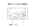
- FIG. 2 is an explanatory diagram schematically showing an image obtained by placing gauze impregnated with a diluted G solution in the abdominal cavity of a pig and photographing it with an endoscopic camera.
- FIG. 7A is an explanatory diagram showing a near-infrared image of the gauze in FIG. 7A.
- FIG. 3 is an explanatory diagram schematically showing an image obtained by placing gauze impregnated with a diluted E solution in the abdominal cavity and photographing with an endoscopic camera.
- FIG. 8A is an explanatory diagram showing a near-infrared image of the gauze in FIG. 8A.
- FIG. 2 is an explanatory diagram schematically showing an image obtained by placing gauze impregnated with a diluted N solution in the abdominal cavity and photographing with an endoscopic camera.
- FIG. 9A is an explanatory diagram showing a near-infrared image of the gauze in FIG. 9A.
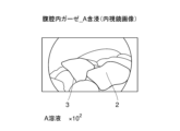
- FIG. 3 is an explanatory diagram schematically showing an image obtained by placing gauze impregnated with a diluted solution of solution A in the abdominal cavity and photographing with an endoscopic camera.
- FIG. 8A is an explanatory diagram showing a near-infrared image of the gauze in FIG. 8A.
- FIG. 2 is an explanatory diagram schematically showing an image obtained by placing gauze impre
- FIG. 10A is an explanatory diagram showing a near-infrared image of the gauze in FIG. 10A.
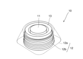
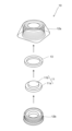
- FIG. 2 is a perspective view showing a configuration example of a CV port. It is a sectional view of the above-mentioned CV port. It is an exploded perspective view of the above-mentioned CV port.
- FIG. 2 is an explanatory diagram schematically showing a state in which rings obtained by molding an epoxy resin are arranged.
- FIG. 14A is an explanatory diagram showing a near-infrared image of each ring in FIG. 14A.
- FIG. 14A is an explanatory diagram showing a near-infrared image of a ring formed by adding a solution having a concentration of ICG four times higher than that of each ring in FIG.
- FIG. 3 is an explanatory diagram schematically showing a state in which the CV port and the comparison port are arranged side by side.
- FIG. 3 is an explanatory diagram showing a near-infrared image of the CV port having an index member molded using G solution.
- FIG. 3 is an explanatory diagram showing a near-infrared image of the CV port having an index member molded using E solution.
- FIG. 3 is an explanatory diagram showing a near-infrared image of the CV port having an index member molded using an N solution.
- FIG. 7 is an explanatory diagram showing a near-infrared image of the CV port having an index member molded using Solution A.
- this embodiment is an illustration for explaining the present invention, and is not intended to limit the present invention to the following content.
- the present invention can be implemented with appropriate modifications within the scope of its gist.
- a numerical range is described as AA to BB, it is assumed that the numerical range includes the lower limit AA and upper limit BB.
- the fluorescent labeling composition according to the present embodiment is a fluorescent labeling composition containing a compound (A) represented by the following formula (1) and a hydroxyl group-containing organic compound (B).
- Compound (A) includes indocyanine green ("ICG”) and its derivatives ("indocyanine green derivative", "ICG derivative”).
- ICG and ICG derivatives may be collectively referred to as “indocyanine green compounds"("ICGcompounds”), etc.
- R 1 and R 2 each independently represent hydrogen, an alkyl group having 1 to 13 carbon atoms, an alkoxy group having 1 to 13 carbon atoms, or a sulfonate group, and p is an integer of 1 to 5. and m and n are each independently an integer from 1 to 12.
- Component (A): indocyanine green compound Compound (A) represented by formula (1) includes indocyanine green (ICG).
- ICG is a compound (CAS No. 3599-32-4) having a structure represented by the following formula (1a), and is a fluorescent organic dye whose excitation light and fluorescence are both in the near-infrared region.
- Formula (1a) is a case where R 1 and R 2 are both hydrogen, p is 2, and m and n are both 4 in formula (1).
- R 1 and R 2 each independently represent hydrogen, an alkyl group having 1 to 13 carbon atoms, an alkoxy group having 1 to 13 carbon atoms, or a sulfonate group; It is preferably an alkyl group having 1 to 8 carbon atoms or an alkoxy group having 1 to 8 carbon atoms, more preferably hydrogen, an alkyl group having 1 to 4 carbon atoms, or an alkoxy group having 1 to 4 carbon atoms. It is even more preferable that there be.
- p is an integer of 1 to 5, preferably 1 to 4, preferably 2 to 3, and more preferably 2.
- n and n are each independently an integer of 1 to 12, preferably 1 to 8, more preferably 2 to 6, even more preferably 3 to 5, and Even more preferably.
- ICG hardly absorbs excitation energy with a wavelength of 600 nm or less, but absorbs excitation energy with a wavelength of 650 to 900 nm and emits fluorescence. For this reason, it is difficult to visually recognize fluorescence when irradiated with visible light, but it is easy to visualize the fluorescence emitted by irradiation with near-infrared light, which is excitation light, by receiving it with a fluorescence microscope or camera. becomes. Therefore, when the composition for fluorescent labeling according to the present embodiment is used for biological fluorescence imaging in blood, the excitation light of ICG is not absorbed by hemoglobin, etc., which has strong absorption in the visible light region of 600 nm or less. .
- ICG is a near-infrared fluorescent organic dye suitable for observing living tissue, that is, observing the conditions of blood vessels, lymph vessels, organs, and the like.
- ICG may exhibit unstable fluorescent coloring, may not be able to obtain sufficient fluorescent intensity, or may become deactivated in a short period of time. Therefore, in clinical practice, conventional ICG is not used in situations that require segment identifiability, such as determining the resection site in surgical operations, and situations that require continuous monitoring over a long period of time. Biofluorescence imaging is insufficient, and there are areas that need improvement.
- the present embodiment by using ICG together with a hydroxyl group-containing organic compound to be described later, stable fluorescent coloring can be obtained and sufficient fluorescent intensity can be obtained, so observation of fluorescently contrasted regions, etc. Excellent partition identifiability can be obtained to the extent that the target structure and the like can be more clearly identified. Furthermore, since the light emission time is long, the observation target can be observed for a long time.
- ICG derivatives that share a basic skeleton with ICG (see formula (1a)), in which R 1 and R 2 are both hydrogen, and p is 1. This also applies to cases where the following is used (excluding the case where m and n are both 4).
- the fluorescent organic dye contains only the compound represented by formula (1) (ICG-based compound). That is, it is preferable that the fluorescent organic dye contains only ICG, an ICG derivative, or both.
- the azo-boron complex compound as disclosed in Patent Document 3 and Patent Document 4 is not substantially contained.
- “not substantially contained” or “not substantially mixed” means that the component is not actively added or mixed, and does not mean that the component is inevitably contained or mixed. It is not excluded.
- the most desirable form of "substantially no content” is the case where the content is zero.
- the hydroxyl group-containing organic compound (B) is an organic compound containing a hydroxyl group (OH group) as a functional group.
- a hydroxyl group (OH group) as a functional group.
- an alcoholic hydroxyl group-containing compound (B1) can be used.
- cellulose (B2) or silk (B3) can be used as the hydroxyl group-containing organic compound (B).
- Silk (B3) is a protein that includes hydroxyl group-containing amino acids such as tyrosine and serine as part of its composition.
- hydroxyl group-containing organic compound (B) since water is an inorganic compound, it is not included in the above-mentioned hydroxyl group-containing organic compound (B). Furthermore, when applying the ICG compound to a resin material described below, a polymer obtained by polymerizing a monomer containing a hydroxyl group, such as an epoxy resin (B4), can be used.
- the alcoholic hydroxyl group-containing compound (B1) is not particularly limited, but aliphatic alcohols are preferred. More preferably, the aliphatic alcohols are aliphatic alcohols having 1 to 10 carbon atoms. The aliphatic alcohol having 1 to 10 carbon atoms preferably has 1 to 5 carbon atoms, even more preferably 1 to 4 carbon atoms.
- alcoholic hydroxyl group-containing compound (B1) examples include, but are not limited to, monoalcohols such as methanol, ethanol, isopropyl alcohol, and propylene glycol; diols such as diethylene glycol; triols such as glycerin; and mannitol. sugar alcohols, etc.
- monoalcohols such as methanol, ethanol, isopropyl alcohol, glycerin, etc.
- diols such as diethylene glycol
- triols such as glycerin
- mannitol. sugar alcohols etc.
- ethanol, isopropyl alcohol, glycerin, etc. are preferred from the viewpoint of cytotoxicity and tissue damage.
- glycerin and the like are more preferable.
- the alcoholic hydroxyl group-containing compound (B1) may be used alone or in combination of two or more.
- the content of compound (A) in the fluorescent labeling composition is not particularly limited, but is preferably 0.0000001 to 10% by mass, more preferably 0.0000001 to 1% by mass, and 0.000001% by mass. It is more preferably from 1% by mass, and even more preferably from 0.000001 to 0.6% by mass.
- concentration quenching phenomenon may occur in which the fluorescence intensity (quantum yield) decreases.
- the concentration quenching phenomenon can be effectively suppressed. As a result, it is possible to further improve the compartment identification when fluorescent light is emitted, and the light emission time can also be made longer (however, the effects of this embodiment are not limited to these).
- the content of the alcoholic hydroxyl group-containing compound (B1) in the fluorescent labeling composition is not particularly limited, but is preferably 90 to 99.9999999% by mass, and preferably 99 to 99.9999999% by mass.
- the content is more preferably from 99 to 99.999999% by mass, even more preferably from 99.4 to 99.999999% by mass.
- the content combination of compound (A) and alcoholic hydroxyl group-containing compound (B1) is such that the content of compound (A) is 0.0000001 to 10% by mass, and the content of alcoholic hydroxyl group-containing compound (B1) is 0.0000001 to 10% by mass. ) is preferably 1 to 90% by mass.
- the content ratio of the alcoholic hydroxyl group-containing compound (B1) to a total of 100 parts by mass of the compound (A) and the alcoholic hydroxyl group-containing compound (B1) is not particularly limited, but it may be contained in a range of 97 to 99.99998 parts by mass.
- the content is preferably from 99.96 to 99.9999 parts by mass, and even more preferably from 99.4 to 99.9997 parts by mass.
- the fluorescent labeling composition according to the present embodiment does not substantially contain DMSO. Similarly, it is preferably substantially free of chloroform. By not substantially containing these organic solvents, the above-mentioned advantages can be further improved. Most preferably, the content of DMSO and chloroform is zero.
- composition for fluorescent labeling may further contain other additive components.
- additive components include components added to contrast media, such as sodium chloride, sodium dihydrogen phosphate, sodium hydrogen phosphate, sodium amidotrizoate, and sodium amidotrizoate meglumine. , iohexol and the like.
- a liquid fluorescent labeling composition is administered into a living body by intraarterial or intravenous injection, and a fluorescence observation device (compatible with excitation light and fluorescence of compound (A)) is used. Contrast imaging can be performed using a camera, etc.). That is, after compound (A) is intravenously injected, the surgical field is irradiated with near-infrared light (excitation light) using a fluorescence observation device, allowing for not only visual observation but also fluorescence observation using near-infrared light. can do. This makes it possible to accurately grasp the state of the surgical field.
- a fluorescent labeling composition For example, by administering a fluorescent labeling composition into the blood, it is possible to determine how far sufficient blood flow has reached. If blood flow is flowing normally, fluorescence will emit light within a relatively short period of time, from a few seconds to a few minutes. That is, if the fluorescent light emission is sufficient, it can be determined that sufficient blood flow is being delivered. Note that the compound (A) becomes tough by binding to blood proteins, and emits fluorescence when irradiated with excitation light.
- a liquid fluorescent labeling composition is injected under the skin near the tumor or in the areola, and then imaged using the above-mentioned fluorescence observation device (camera, etc.). be able to.
- compound (A) is strengthened by binding to plasma proteins in the lymph, and emits fluorescence upon irradiation with excitation light.
- the fluorescent labeling composition When used for angiography, sentinel lymph node identification, etc., as mentioned above, the fluorescent labeling composition should be used in a liquid (25°C, relative The humidity is preferably 50%.
- the composition for fluorescent labeling is a liquid, it may be stored as a highly concentrated solution (for example, a concentrated solution) and diluted at the time of use. The dilution ratio at that time may be set so that the diluent has the above-mentioned suitable concentration and content.
- the concentrated solution and the diluted solution can be prepared, for example, using a vial of distilled water that is attached to the commercially available compound (A).
- composition for fluorescent labeling can also be used clinically as an injection, as described below.
- the injection agent will be described later, but it may be a liquid.
- the injection agent may be in a gel-like or semi-solid form from the viewpoint of imparting a certain viscosity or shape-retaining property.
- at least one component ((D) component) selected from the group consisting of (D) sodium alginate and sodium hyaluronate may be blended.
- the fluorescent labeling composition according to the present embodiment is used as various materials for medical instruments and the like, it is preferable that the fluorescent labeling composition further contains a resin (C).
- a resin (C) for example, by using the fluorescent labeling composition as a molding material for medical devices such as stents, tubes, catheters, clips, fluorescent parts around the septum of subcutaneous implantable ports, filaments for 3D printers, and resin fiber materials. , such medical instruments can be made to emit fluorescence. Note that details of the medical device will be described later.
- the resin (C) in view of the fact that ICG is water-soluble, it is desirable to use a material that does not undergo hydrolysis and has a melting point lower than the melting point of ICG (about 230° C.).
- a material that does not undergo hydrolysis and has a melting point lower than the melting point of ICG (about 230° C.) For example, at least one selected from the group consisting of polyurethane resin, olefin resin, epoxy resin, vinyl chloride resin, fluorine resin, polycarbonate resin, polyamide resin, ABS resin, acrylic resin, and silicone resin.
- it contains seeds.
- These resins are easily available and have high stability, so they are suitable as molding materials for medical instruments and the like. It is also suitable in that it does not adversely affect the fluorescence properties of compound (A).
- a polyurethane resin is a suitable resin.
- the alcoholic hydroxyl group-containing compound (B1) it is better to use a high boiling point organic solvent (e.g. glycerin) than a low boiling point organic solvent to effectively elute compound (A) under high temperature and humidity. It is desirable from the viewpoint of suppressing
- Examples of the olefin resin include polyethylene and polypropylene.
- the epoxy resin (B4) is represented by the following structural formula.
- the epoxy resin (B4) does not necessarily require the alcoholic hydroxyl group-containing compound (B1) because the hydroxyl groups it contains act as a toughening factor for ICG. Therefore, the epoxy resin (B4) has extremely strong fluorescent activity compared to other resins. Examples include epoxy resins made by glycidyl etherification of bisphenol A, bisphenol F, or novolak, etc.; epoxy resins made by adding propylene oxide, ethylene oxide, or polyalkylene glycol to bisphenol A and glycidyl etherification; aliphatic epoxy resins; alicyclic resins; Epoxy resin; examples include polyether epoxy resins. Furthermore, since the epoxy resin (B4) can be coated on metal, it is suitable as a material to be attached to the tips of surgical instruments such as various forceps or scissors.
- vinyl chloride-based resins include vinyl chloride homopolymers, vinyl chloride-vinyl acetate copolymers, vinyl chloride-ethylene copolymers, vinyl chloride-propylene copolymers, vinyl chloride-styrene copolymers, and vinyl chloride-vinyl acetate copolymers.
- vinyl-vinylidene chloride copolymer vinyl chloride-acrylic acid ester copolymer, vinyl chloride-maleic acid ester copolymer, vinyl chloride-methacrylic acid ester copolymer, vinyl chloride-acrylonitrile copolymer, and the like.
- fluororesin examples include polytetrafluoroethylene, tetrafluoroethylene-perfluoroalkyl vinyl ether copolymer, tetrafluoroethylene-hexafluoropropylene copolymer, tetrafluoroethylene-fluoroalkyl vinyl ether-fluoroolefin copolymer, Examples include ethylene-tetrafluoroethylene copolymer and ethylene-trichlorofluoroethylene copolymer.
- polycarbonate resin examples include aromatic polycarbonate resins, aliphatic polycarbonate resins, and aromatic-aliphatic polycarbonate resins containing bisphenol A or the like as a polymerization component.
- polyamide resins examples include polytetramethylene adipamide (nylon 46), polytetramethylene sebaamide (nylon 410), polypentamethylene adipamide (nylon 56), and polypentamethylene sebaamide (nylon 510).
- polycaproamide (nylon 6), polyhexamethylene adipamide (nylon 66), polyhexamethylene sebacamide (nylon 610), polyhexamethylene dodecamide (nylon 612), polydecamethylene adipamide (nylon 106), polydecamethylene sebaamide (nylon 1010), polydecamethylene dodecamide (nylon 1012), polyundecaneamide (nylon 11), polyundecamethylene adipamide (nylon 116), polydodecanamide (nylon 12) ), polyxylene adipamide (nylon XD6), polyxylene sebacamide (nylon (nylon 4T), polypentamethylene terephthalamide (nylon 5T), polyhexamethylene terephthalamide (nylon 6T), polyhexamethylene isophthalamide (nylon 6I), polynonamethylene terephthalamide (nylon 9T), polydecamethylene terephthalamide (nylon 10T), polyundecamethylene terephthalamide
- ABS resins include acrylonitrile butadiene styrene (ABS), acrylonitrile styrene acrylic (ASA), acrylonitrile ethylene styrene (AES), polyethylene chloride acrylonitrile styrene (ACS), and ⁇ -methylstyrene.
- ABS resins include ABS resin, flame-retardant ABS resin (FR-ABS), reinforced ABS resin, and phenylmaleimide-based ABS resin.
- acrylic resins include homopolymers such as polymethyl methacrylate (PMMA) and polyethyl methacrylate; methyl methacrylate-styrene copolymers and methyl methacrylate- ⁇ -methylstyrene copolymers; Examples include copolymers.
- PMMA polymethyl methacrylate
- PEG polyethyl methacrylate
- methyl methacrylate-styrene copolymers methyl methacrylate- ⁇ -methylstyrene copolymers
- Examples include copolymers.
- silicone resin examples include methyl silicone resin, methylphenyl silicone resin, phenyl silicone resin, epoxy-modified silicone resin, polyester-modified silicone resin, and acrylic-modified silicone resin.
- acetal resin may undergo hydrolysis when mixed with ICG, and may emit harmful substances such as formaldehyde. For this reason, it is desirable that the resin (C) does not contain an acetal resin.
- the resin (C) may be used alone or in combination of two or more.
- the content of the resin (C) in the fluorescent labeling composition is not particularly limited, but is preferably 80 to 99.99998% by mass, more preferably 85 to 99.9999% by mass, and 90 to 99% by mass. More preferably, it is .9997% by mass.
- the content of the resin is not particularly limited, but is preferably 80 to 99.99998% by mass, more preferably 85 to 99.9999% by mass, and 90 to 99% by mass. More preferably, it is .9997% by mass.
- the state of the composition for fluorescent labeling at 25° C. and 50% relative humidity is preferably solid or semi-solid.
- a semi-solid state is different from a liquid state and means that it has a shape retention property like a paste state or the like.
- the above-mentioned resin (C) may be blended, or the alcoholic hydroxyl group-containing compound (B1) in a solid or semi-solid state may be blended. You may.
- the alcoholic hydroxyl group-containing compound (B1) is preferably glycerin or the like. Further, other solid or semi-solid components may also be blended.
- the method for producing a composition for fluorescent labeling of the present embodiment includes a mixing step of mixing the above-described compound (A) and a hydroxyl group-containing organic compound (B).
- the hydroxyl group-containing organic compound (B) the above-mentioned alcoholic hydroxyl group-containing compound (B1) can be used.
- the mixing method in the mixing step is not particularly limited, and any known method can be selected.
- suitable conditions can be adopted as appropriate.
- the mixing step it is preferable to obtain a composition for fluorescent labeling containing 0.0000001 to 10% by mass of the compound (A) and 1 to 90% by mass of the alcoholic hydroxyl group-containing compound (B1).
- the mixing process does not necessarily have to be carried out in one step.
- a step of obtaining a highly concentrated concentrate may be performed, and then a step of diluting the concentrated liquid to the above concentration range at the time of use or the like may be performed. That is, the dilution concentration during use is preferably within the above-mentioned concentration range.
- a step of heating the mixture may be performed.
- the above-described composition for fluorescent labeling can be suitably used as a fluorescent probe.
- it can be used as an organic compound type fluorescent probe derived from compound (A).
- the excitation light is not absorbed by hemoglobin or the like, so the excitation light can reach deep inside the living tissue and its state can be visually recognized and observed. can do.
- fluorescence it has excellent compartment identification and the composition itself has a long lifespan, so it continues to emit light for a long time. Because of these advantages, the fluorescent labeling composition of this embodiment is suitable as a fluorescent probe.
- the fluorescent labeling composition described above can be suitably used as an injection.
- a preferred aspect of the injection of this embodiment is a labeling injection for labeling an object present on a mucous membrane or skin, and is an injection containing the above-described fluorescent labeling composition.
- the above-mentioned injection agent is injected under the mucous membrane or skin where the target object is located, and can be labeled by being irradiated with excitation light of compound (A).
- injections can be used for various local injections under the mucous membrane or skin of a site to be excised, such as a tumor.
- an injection agent is injected under the mucous membrane or skin around the lesion and is caused to emit fluorescence by irradiating it with excitation light. .
- the planned resection line of the lesion (the boundary between the side to be left and the side to be excised) can be accurately identified. Further, by using both visual findings and fluorescence observation by a doctor, a more appropriate planned cutting line can be determined.
- the alcoholic hydroxyl group-containing compound (B1) as the hydroxyl group-containing organic compound (B) is preferably glycerin or mannitol from the viewpoint of safety to the human body. These may be used alone or in combination of two or more.
- the injection according to this embodiment can also contain at least one of sodium alginate and sodium hyaluronate as component (D).
- This component (D) can also function as a viscosity enhancer.
- the injection agent can be injected into the submucosal layer or the subcutaneous layer near the lesion, for example, and the injected area can be expanded so as to rise.
- the above-mentioned fluorescence observation device such as a camera
- the position of the lesion can be accurately grasped, and the scheduled resection line of the lesion can be identified more accurately.
- the content of the component (D) in the injection agent according to the present embodiment is not particularly limited, but the total content of the components (D) is preferably 0.01 to 10% by mass, and 0.05 to 5% by mass. %, even more preferably 0.05 to 3% by mass, even more preferably 0.1 to 1% by mass. However, if sufficient viscosity and local localization are obtained, it is effective even if the injection does not contain component (D) at all.
- the fluorescent labeling composition described above can be suitably used as a syringe filling.
- the syringe filling is configured by filling a syringe (syringe barrel) with the fluorescent labeling composition of this embodiment in advance.
- the syringe filling is also called a prefilled syringe or the like.
- the material and size and shape of the syringe are not particularly limited, and suitable conditions can be selected depending on the application.
- the syringe may be made of glass or resin, for example.
- the tube of a local injection needle for submucosal injection may also be filled with the fluorescent labeling composition, and the local injection needle may be connected to a prefilled syringe.
- the compound (A), the hydroxyl group-containing organic compound (B), other solvents, and additive components are contained from the viewpoint of suppressing the concentration quenching phenomenon and ensuring sufficient fluorescence emission intensity and emission time. It is important to appropriately adjust the amount and content ratio. However, it is complicated to mix these medicinal solutions at the time of surgery. By filling a syringe (+local injection needle tube) with a fluorescent labeling composition prepared in advance at an accurate content ratio, such complicated work can be omitted at the time of surgery.
- a syringe is filled with a concentrated solution in which the content ratio of the compound (A) and the alcoholic hydroxyl group-containing compound (B1) as the hydroxyl group-containing organic compound (B) is within the above-mentioned preferred range, and at the time of use, It can be used after being diluted with physiological saline or water for injection.
- the syringe filling according to the present embodiment is not limited to a structure in which the syringe is filled with a concentrated solution of the fluorescent labeling composition.
- a syringe filling may be constructed by filling a syringe with the fluorescent labeling composition as it is at an injectable concentration (diluted solution).
- a medical device can be produced using the above-described composition for fluorescent labeling as a molding material.
- Such medical devices include stents, tubes, catheters, clips, fluorescent parts around the septum of subcutaneous implantable ports, filaments for 3D printers, resin fiber materials (e.g. gauze threads, sutures, etc.), Other examples include surgical instruments such as various forceps or scissors whose tips are coated or the like.
- medical devices to which the fluorescent labeling composition is applied are particularly stents, tubes, catheters, fluorescent parts around the septum of subcutaneous implantable ports, filaments for 3D printers, resin fiber materials (e.g. The material is preferably one selected from the group consisting of medical gauze, sponges, tuppels, cotton balls, tampons, silk threads, sponges, etc.) and surgical instruments such as various forceps or scissors.
- a fluorescent labeling composition is included in the material constituting the stent.
- the stent can be caused to emit fluorescence by placing the stent in a living body and irradiating the stent with near-infrared rays, which is excitation light of compound (A).
- the stent is, for example, a bile duct stent or a ureteral stent
- the location of the stent can be accurately determined by the fluorescent light emitted from the stent. This can reduce the risk of accidentally damaging the bile duct or ureter during surgery.
- a fluorescent labeling composition is included in the material constituting the tube.
- the tube By placing the tube in a living body and irradiating the tube with near-infrared rays, which is excitation light of compound (A), the tube can be caused to emit fluorescence.
- near-infrared rays which is excitation light of compound (A)
- the tube can be caused to emit fluorescence.
- the placement position of the tube can be accurately determined by fluorescence emission, so even when performing laparoscopic surgery, the site of intestinal obstruction, etc. can be identified more accurately.
- a fluorescent labeling composition is included in the material constituting the catheter.
- the catheter can be caused to emit fluorescence by placing the catheter in a living body and irradiating the catheter with near-infrared rays, which is excitation light of compound (A).
- near-infrared rays which is excitation light of compound (A).
- the placement position of the catheter can be accurately ascertained by fluorescence emission, so it is possible to avoid the risk of accidentally damaging the ureter during surgery.
- a subcutaneous implantable port in which the material constituting the septum or housing portion contains a fluorescent labeling composition does not contain a drug.
- the resin will come into direct contact with the patient's subcutaneous tissue for a long period of time, which is unfavorable from a medical safety standpoint.
- a septum that is repeatedly punctured with a needle has the problem of coring, where the material is gradually worn away, and it is undesirable to include drugs, including concerns about decreased durability.
- the housing part is impregnated with a drug to cause fluorescence to develop, there is a concern that the emission range will be too wide and the central septum part will not be fluorescently negative.
- the fluorescent labeling composition is built into the housing around the septum (if it is present inside the outer surface of the housing), the position of the septum can be recognized without the light-emitting part coming into contact with the patient's subcutaneous tissue. becomes possible.
- the fluorescent labeling composition may be in the form of a ring or a collection of spots as long as it is arranged around the septum.
- the method for manufacturing the medical device of this embodiment described above is not particularly limited, but any known method can be adopted.
- a manufacturing method including a step of injection molding the above-described composition for fluorescent labeling using a mold or the like can be adopted.
- the medical device may be manufactured by extrusion molding, compression molding, blow molding, calendar molding, inflation molding, thermoforming, or the like.
- a fluorescent labeling composition is included in the fiber material.
- the resinous fiber material include gauze threads, surgical suture threads, and the like.
- gauze as in Patent Document 4, a resin fiber material impregnated with a fluorescent labeling composition is woven into a part of the cotton cloth constituting the gauze, and the excitation light of compound (A) is used to It is conceivable that by irradiating the gauze with infrared rays, the fiber material forming a part of the gauze can be caused to emit fluorescence.
- the luminescence intensity may be insufficient to be used as an indicator for search or surgical operation in the event of dissipation.
- the blending ratio of the resin fiber material is increased, the water absorbency will decrease and there is a risk that the gauze will not be able to fulfill its original function. For this reason, it is desirable that the entire cotton fabric constituting the gauze contain the fluorescent labeling composition.
- the suture when the suture contains a composition for fluorescent labeling, the suture emits fluorescence by irradiating the suture with near-infrared rays, which is excitation light of compound (A).
- the drug-containing fibers come into semi-permanent contact with the patient's tissue, which is unfavorable in terms of medical safety.
- the needle in the method in which the needle is fluorescently colored, the needle is removed from the body, but resin adheres to the needle, which may impair its original sharpness.
- an epoxy resin containing compound (A) for example, is used as the adhesive that connects the needle and thread in a "needle thread" in which a needle is attached to the tip of the suture thread, the above-mentioned problems can be solved. It becomes possible to find a lost needle without causing any trouble.
- such a resin fiber material can be suitably used not only for the purpose of use in the medical field (medical use) but also as a luminous fiber, luminous material, etc. in a wide range of fields. Further, since the fiber material is made of resin, the compound (A) can be uniformly dispersed and blended into the resin, and therefore the entire material can uniformly emit fluorescence.
- the composition for fluorescent labeling of this embodiment (for example, compound (A) + hydroxyl group-containing organic compound (B)) may be kneaded with resin and thread-spun.
- compound (A) alone may be kneaded with a resin and then thread-spun.
- the medical fiber material of this embodiment includes the above-mentioned compound (A) and a fiber material containing a hydroxyl group-containing organic compound (B), and can emit light when irradiated with excitation light of the compound (A). It is.
- the medical fiber material is irradiated with the excitation light of the compound (A)
- fluorescence is obtained from the medical fiber material, and the fluorescence has excellent zone identification and a long luminescence time.
- the hydroxyl group-containing organic compound (B) contained in the fiber material preferably contains cellulose (B2), and also consists of animal protein such as silk (B3). May contain fiber.
- Such medical fiber materials include, but are not particularly limited to, medical gauze, sponges, tuppels, cotton balls, tampons, silk threads, and fiber materials constituting these.
- medical gauze sponges, tuppels, cotton balls, tampons, silk threads, and fiber materials constituting these.
- the medical fiber material according to the present embodiment when used as medical gauze, it can contribute to preventing gauze from being left behind in the body during surgery in clinical practice such as surgery. An example of how to use such medical gauze will be described below.
- X-ray gauze contrast threads appear thin and white in X-ray images, so if they overlap with bones, they are difficult to see and may be overlooked even when looking at X-ray images.
- the presence of the entire gauze can be clearly confirmed by emitting green or blue fluorescence, so the gauze can be easily confirmed even though it is a simple method.
- near-infrared light is used instead of X-rays, the exposure dose to patients and staff can be reduced, resulting in high safety.
- the medical gauze according to this embodiment can achieve excellent compartment identification and long luminescence time is that the compound (A) and cellulose (B2), which is the hydroxyl group-containing organic compound (B) contained in the gauze, are It is thought that this is because the hydroxyl group is strongly bonded with the hydrogen bond and takes a stable form (however, the effects of this embodiment are not limited thereto). Therefore, in surgery, by placing gauze in advance at the target ablation point and using the fluorescence of the gauze as an indicator, the operation can be carried out efficiently.
- the gauze used only needs to contain a hydroxyl group-containing organic compound (B) (for example, cellulose (B2)), and other materials, dimensions, and shapes are not particularly limited.
- B hydroxyl group-containing organic compound
- the gauze used may be angular gauze used as surgical gauze (operating gauze), etc., or may be cut gauze, folded gauze, wide gauze, etc. that is applied to the wound or the injured area.
- the gauze used may be sterilized using ethylene oxide gas (EOG), an autoclave, or the like.
- EOG ethylene oxide gas
- the amount of compound (A) added is not particularly limited, it is preferable to control the amount added to a certain level, for example, from the viewpoint of accurately grasping the amount of bleeding during a surgical operation.
- the amount of compound (A) added per m 2 of gauze is preferably 0.001 to 10 g, more preferably 0.01 to 5 g, and even more preferably 0.1 to 3 g. . Further, even if blood adheres to the gauze, the visibility of the fluorescence is not inhibited, and the binding of proteins in the blood to ICG further enhances the luminescence.
- the medical fiber material according to this embodiment may further contain the above-mentioned alcoholic hydroxyl group-containing compound (B1). Further, the medical fiber material may contain other additive components including water, instead of or in addition to the alcoholic hydroxyl group-containing compound (B1). .
- the medical fiber material according to this embodiment may further contain a mordant.
- a mordant By using a mordant, the compound (A) can be fixed to the gauze together with the dye.
- the mordant alum, iron oxide, etc. can be used.
- the medical fiber material according to this embodiment is used as a medical gauze, but the medical fiber material according to this embodiment is not limited to such usage.
- medical fiber materials when medical fiber materials are used as sponges, tuppels, cotton balls, tampons, silk thread (with needles), etc., or as the fiber materials that make up these materials, they emit fluorescence when used, similar to medical gauze. can be done.
- the above-mentioned silk thread (with a needle) may be used, for example, as a target during a second-stage surgery. If the silk thread (with needle) emits fluorescence, the target can be easily recognized, which is very useful when performing such a two-stage surgery.
- the method for manufacturing a medical fiber material according to this embodiment includes an impregnation step and a mordant step.
- a fiber material containing a hydroxyl group-containing organic compound (B) is impregnated with a solution containing the above-described compound (A).
- the mordant step the compound (A) is fixed to the fiber material using a mordant.
- the fiber material is not particularly limited as long as it contains the hydroxyl group-containing organic compound (B) and can be impregnated with a solution containing the compound (A).
- the hydroxyl group-containing organic compound (B) preferably contains cellulose (B2) or silk (B3).
- silk (B3) is a protein having a hydroxyl group-containing amino acid as a constituent component.
- fiber materials include medical gauze, sponges, tuppels, cotton balls, tampons, silk threads (with needles), and fiber materials constituting these. For example, medical gauze, sponges, tuppels, cotton balls, tampons, silk threads (with needles), etc.
- impregnated with the above solution may be directly impregnated with the above solution, or medical gauze, sponges, tuppels, cotton balls, tampons, (with needles), etc.
- a fiber material constituting silk thread or the like may be impregnated with the above solution.
- fiber materials commonly used in the medical field and other fields can also be used.
- the above impregnation step may be performed by spraying.
- impregnation here refers to impregnating the fiber material with the above solution, but it may also be impregnated by immersing the fiber material in the solution, or by spraying the solution onto the fiber material. It may be impregnated by.
- the impregnation step when impregnating a fiber material such as gauze with the solution, the impregnation step includes at least the compound (A) and the alcoholic hydroxyl group-containing compound (B1) as the hydroxyl group-containing organic compound (B). It may also be impregnated with a solution containing it. In this case, the alcoholic hydroxyl group-containing compound (B1) can be used as a solvent for the compound (A).
- Impregnation conditions are not particularly limited, and suitable conditions can be selected as appropriate in consideration of the material, size, shape, etc. of the fiber material.
- the impregnation time is preferably 1 minute to 3 days at room temperature and humidity, and it is preferable to shield from light during impregnation. Note that, as described above, impregnation may be performed by spraying.
- the solution used in the method for producing a medical fiber material may be a composition containing the compound (A), the alcoholic hydroxyl group-containing compound (B1), and water. Note that the above solution does not necessarily need to contain the alcoholic hydroxyl group-containing compound (B1). Therefore, the solution may have a structure containing only compound (A) and water.
- alcoholic hydroxyl group-containing compound (B1) for example, a low boiling point or volatile alcoholic hydroxyl group-containing compound such as methanol, ethanol, isopropyl alcohol, etc. may be used, or a high boiling point alcoholic hydroxyl group-containing compound such as glycerin. Compounds may also be used.
- the compound (A) when gauze is impregnated with the fluorescent labeling composition, the compound (A) is supported on the gauze, and then the alcohol The hydroxyl group-containing compound (B1) is volatilized or removed, and the compound (A) is supported on the gauze.
- gauze is impregnated with the above solution to support the compound (A) on the gauze, and then the alcoholic hydroxyl group-containing compound (B1 ) is supported on the gauze together with compound (A) without being removed.
- alcoholic hydroxyl group-containing compounds (B1) a low boiling point or volatile alcoholic hydroxyl group-containing compound is preferable, ethanol and isopropyl alcohol are more preferable, and ethanol is preferable. is even more preferable.
- a component as the alcoholic hydroxyl group-containing compound (B1) it is possible to use a simple and economical method, and to achieve a state in which only the compound (A) is supported on the medical gauze. I can do it.
- the mordant step using a mordant includes, for example, a step of dyeing the compound (A) onto gauze using the mordant.
- the dyeing step may be pre-mordanting, post-mordanting, or simultaneous mordanting, but post-mordanting is preferable from the viewpoint of dyeing the compound (A) onto the gauze.
- the mordant those mentioned above can be used. Mordant conditions are not particularly limited.
- a protein treatment step may be performed in which the fiber material is impregnated with a protein preparation.
- the compound (A) can be fixed to the gauze together with the dye.
- the protein preparation milk, soy milk, skim milk powder, etc. can be used.
- Sterilization conditions are not particularly limited, and methods known as methods for sterilizing medical fiber materials such as medical gauze can be employed.
- Instruments may be prepared by coating the tips of surgical instruments such as various forceps or scissors with, for example, an epoxy resin containing a fluorescent labeling composition. In this case, the operation can be performed while visually checking the tip of the instrument hidden behind the organ, etc., thereby improving the safety of the surgery.
- the composition for fluorescent labeling according to the present embodiment has at least excellent compartment discrimination to the extent that the structure of the observation target can be identified more accurately, has a long luminescence time, and has a long luminescence time. can be observed over a long period of time, and furthermore, it places less burden on living organisms and is highly economical.
- the excitation light is not absorbed by substances in living tissues such as hemoglobin, and the light can reach deep into living tissues, allowing observation of the conditions of blood vessels, lymph vessels, organs, etc. There is also the advantage that it can be done.
- composition for fluorescent labeling is also useful as a fluorescent probe, injection agent, syringe filler, medical instrument, medical fiber material, etc., and can exhibit the above-mentioned advantages.
- the method for producing the composition for fluorescent labeling and the medical fiber material has advantages as a production method because easily available materials or components can be used and production can be performed by a simple method.
- the composition for fluorescent labeling, the fluorescent probe, the injection agent, the syringe filling, the medical device, and the medical fiber material according to the present embodiment have the various advantages described above, and therefore, the composition is an ICG-based compound (compound (A)). It can be suitably used for biofluorescence imaging using. For example, in the medical field, it can be applied to angiography, tumor fluorescence imaging, identification of regional lymph nodes including sentinel lymph nodes, marking of surgical operation targets, marking of organs to avoid damage, prevention of remaining body parts, prevention of dissipation, etc. I can do it. Furthermore, it is expected to be applied in fields other than medical settings, such as basic medical research, life science, regenerative medicine, various diagnostics, architectural engineering, and entertainment. That is, the composition for fluorescent labeling of this embodiment is not limited to medical use, and can be expected to be applied to a wide range of other uses.
- the fluorescent marking composition described in this embodiment may be applied to the building. By kneading or coating the material, it is possible to identify a specific location (location where the fluorescent labeling composition is present) without the user knowing. Furthermore, if a "glowing contact lens" is made using the fluorescent labeling composition described in this embodiment, the performer who wears the "luminous contact lens" on his or her eyes will not feel the fluorescence and only the viewer will be able to see the eye. Can recognize light (emission from contact lenses). In other words, the fluorescent labeling composition of this embodiment can be expected to be applied to theatrical productions.
- PP polypropylene
- PVC polyvinyl chloride
- LDPE low-density polyethylene
- EVA ethylene-vinyl acetate copolymer resin
- TPU thermoplastic polyurethane
- phr is an abbreviation for per hundred resin, and is a unit that expresses the ratio of pigment blended when the weight of the resin is 100. For example, if Ag pigment is contained in 100 g of resin, the ratio of the pigment can be said to be A (phr).
- the kneading procedure is as follows. (Step 1: Pre-kneading) The resin was placed in a preheated mixer and kneaded until plasticized. As the mixer, Labo Plast Mill 4M150 manufactured by Toyo Seiki Seisakusho Co., Ltd. was used. Note that "Laboplasto Mill” is a registered trademark of Toyo Seiki Seisakusho Co., Ltd. This process was performed for each resin prepared in advance. Kneading was performed for 5 minutes at a temperature set for each resin.
- the above kneading temperatures are: polypropylene: 170°C, polyvinyl chloride: 150°C, low density polyethylene: 140°C, ethylene/vinyl acetate copolymer resin: 140°C, thermoplastic polyurethane: 150°C. there were.
- both kneading temperatures are lower than the melting point (230° C.) of ICG.
- Step 2 Pigment kneading
- resin + pigment After confirming that the resin was sufficiently plasticized in step 1, pigment was added and kneaded.
- Step 3 Compression molding
- the above sample was cut into pieces using scissors. Then, the cut sample was sandwiched between a pair of heat-resistant polyimide films, and the sample-containing film was placed between a pair of metal plates (for example, stainless steel plates). Subsequently, a pair of metal plates containing a sample-containing film were placed between a pair of spacers. Thereafter, the pair of spacers were pressed toward each other, and the sample was melted and compressed for 1 minute to the desired thickness to form a sheet.
- the compression molding temperature was the same as in steps 1 and 2. After forming, the pair of metal plates were placed on a mounting table and left to cool at room temperature with a weight placed on them. Note that two types of sheet thicknesses were obtained: 1 mm thick (110 mm long x 110 mm wide) and 0.5 mm thick (125 mm long x 125 mm wide).
- G solution is a solution in which 25 mg of ICG is mixed and dissolved in 10 ml of glycerol.
- Solution E is a solution in which 25 mg of ICG is mixed and dissolved in 10 ml of ethanol.
- the N solution is a solution in which 25 mg of ICG is mixed and dissolved in 10 ml of distilled water.
- Solution A is a solution in which 25 mg of ICG is mixed and dissolved in 10 ml of 5% BSA solution. Note that BSA is bovine serum albumin. Distilled water did not contain ICG and was prepared for comparison with a stock solution containing ICG.
- FIG. 1A schematically shows a state in which each stock solution is placed in containers (transparent containers) and arranged side by side.
- the containers are lined up in this order from the left: G solution, E solution, N solution, A solution, and distilled water.
- An ICG standard card 1 is placed on the right side of the container containing distilled water.
- the ICG reference card 1 has a light emitting area 1a.
- the light emitting region 1a is a region containing ICG, and emits fluorescence when irradiated with excitation light (near infrared light).
- the presence or absence of light emission during irradiation with near-infrared light and the brightness of the light-emitting portion are compared and evaluated relatively, using the light-emission brightness of the light-emitting area 1a of the ICG reference card 1 as a reference. That is, the ICG reference card 1 is used for relative comparison and evaluation of luminance.
- Figure 1B shows an image (hereinafter also referred to as a near-infrared image) obtained by irradiating each container with near-infrared light and photographing each container with a near-infrared camera (Olympus VISERAELITE II). . From the figure, it can be seen that in the undiluted state, the luminance of the G solution and the E solution is high.
- a near-infrared image obtained by irradiating each container with near-infrared light and photographing each container with a near-infrared camera (Olympus VISERAELITE II).
- diluted solutions were prepared by diluting each stock solution 5 times, 10 times ( ⁇ 10 1 ), 100 times ( ⁇ 10 2 ), 1000 times ( ⁇ 10 3 ), and 10000 times ( ⁇ 10 4 ). Note that dilution was performed here using the solvent of each stock solution.
- Figure 2 shows near-infrared images obtained for the G solution. Note that in FIG. 2, for convenience, the container containing the 5-fold diluted solution is omitted (the same applies to FIGS. 3 to 5). From FIG. 2, it can be seen that with the G solution, good (high) luminescence brightness can be obtained regardless of the dilution ratio.
- Figure 3 shows a near-infrared image obtained for the E solution. From the same figure, it can be seen that, similarly to the G solution, good (high) luminescence brightness can be obtained with the E solution regardless of the dilution ratio.
- Figure 4 shows near-infrared images obtained for the N solution. From the figure, it can be seen that with the N solution, high emission brightness is obtained when diluted 1000 times, but the emission brightness is low at other dilution ratios.
- Figure 5 shows a near-infrared image obtained for solution A. From the figure, it can be seen that in solution A, high luminescence brightness is obtained from 10-fold dilution to 10000-fold dilution, and in particular, higher luminescence luminance is obtained at 100-fold dilution and 1000-fold dilution.
- a dilution solution with a desired dilution ratio here, distilled water was used, but the solvent of each stock solution may also be used
- a near-infrared image was obtained by impregnating gauze with the diluted solution.
- the gauze Sterase (sterilized, 5 cm x 5 cm) manufactured by Hakujuji Co., Ltd. was used. Note that "Stellase” is a registered trademark of Hakujuji Co., Ltd.
- FIG. 6A schematically shows gauze impregnated with 5-fold, 10-fold, 100-fold, and 1000-fold dilutions of G solution, E solution, N solution, and A solution, respectively, arranged vertically and horizontally. It is shown in In FIG. 6A, gauze impregnated with G solution, E solution, N solution, and A solution are arranged from the top to the bottom, and from the left to the right, 5 times, 10 times, 100 times, 100 times. Lay out each piece of gauze impregnated with twice the amount of each diluted solution. Further, in FIG. 6A, the ICG reference card 1 is placed on the right side of the gauze impregnated with a 1000-fold diluted solution, and the untreated gauze 2 is placed above the ICG reference card 1. The untreated gauze 2 is simply gauze that has not been impregnated.
- FIG. 6B shows a near-infrared image obtained when each gauze in FIG. 6A is irradiated with near-infrared light. From the same figure, it was found that high luminescence brightness was obtained in gauze impregnated with a diluted solution of 10 times to 1000 times for each of the G solution, E solution, N solution, and A solution. In particular, it was found that gauze impregnated with a 100-fold diluted solution provided the highest luminescence brightness.
- FIG. 7A, FIG. 8A, FIG. 9A, and FIG. 10A schematically show images taken with an endoscopic camera when untreated gauze 2 and treated gauze 3 are placed in the abdominal cavity of a pig.
- the treated gauze 3 in FIG. 7A gauze impregnated with a diluted solution obtained by diluting the G solution 100 times was used.
- the treated gauze 3 in FIG. 8A gauze impregnated with a 100-fold dilution of solution E was used.
- the treated gauze 3 in FIG. 9A gauze impregnated with a 100-fold diluted N solution was used.
- gauze impregnated with a 100-fold dilution of solution A was used.
- FIG. 7B, FIG. 8B, FIG. 9B, and FIG. 10B show near-infrared images obtained when near-infrared light is irradiated to each gauze of FIG. 7A, FIG. 8A, FIG. 9A, and FIG. 10A. From these figures, it was found that each treated gauze 3 emitted light with high luminescence intensity when irradiated with near-infrared light in the abdominal cavity.
- FIG. 11 is a perspective view showing a configuration example of a CV port (central venous port) 10 as a subcutaneously implanted port.
- FIG. 12 is a cross-sectional view of the CV port 10 of FIG. 10.
- FIG. 13 is an exploded perspective view of the CV port 10 of FIG. 10. Note that in FIG. 11, the outer shape of the housing portion 12 is shown by broken lines in order to clarify the internal configuration of the CV port 10.
- the CV port 10 includes a septum 11, a housing portion 12, and an indicator member 13.
- the septum 11 is made of, for example, soft silicone rubber.
- the septum 11 integrally includes a large diameter portion 11a and a small diameter portion 11b.
- the small diameter portion 11b has a smaller diameter than the large diameter portion 11a.
- the small diameter portion 11b is located above the large diameter portion 11a coaxially with the large diameter portion 11a.
- a Huber needle for injecting a medicinal solution is inserted into the septum 11 (for example, the small diameter portion 11b).
- the housing part 12 is a cover that holds the septum 11, and holds the septum 11 so that the upper surface of the septum 11 (for example, the small diameter part 11b) is exposed.
- a housing part 12 has an outer housing 12a and an inner housing 12b.
- the outer housing 12a is made of, for example, transparent acrylic resin.
- CV port 10 When CV port 10 is implanted subcutaneously in a patient, a portion of the outer surface (eg, the top surface) of outer housing 12a contacts the patient's skin.
- a thread groove is formed on the inner peripheral surface of the outer housing 12a.
- the inner housing 12b is a back cover located inside the outer housing 12a.
- a thread is formed on the outer peripheral surface of the inner housing 12b.
- the inner housing 12b is fixed to the outer housing 12a by screwing the inner housing 12b inside the outer housing 12a while engaging the threads with the thread grooves.
- a recess 12b1 is formed in the upper part of the inner housing 12b.
- the large diameter portion 11a of the septum 11 is inserted into the recess 12b1 and is sandwiched between the inner housing 12b and the outer housing 12a from above and below.
- a liquid injection chamber 12b2 that accommodates the above-mentioned chemical liquid is formed in the inner housing 12b.
- the liquid injection chamber 12b2 is formed to have a smaller diameter than the recess 12b1, and is located below the recess 12b1.
- the medicinal solution injected into the liquid injection chamber 12b2 through the Huber needle inserted into the septum 11 is introduced into a blood vessel or the like via a catheter (not shown) communicating with the liquid injection chamber 12b2.
- the indicator member 13 is arranged inside the housing part 12 and outside the septum 11. More specifically, the indicator member 13 is located inside the outer shape of the housing portion 12 (particularly the outer housing 12a). Further, the indicator member 13 is arranged on the upper surface of the large diameter part 11a of the septum 11, and is arranged radially apart from the small diameter part 11b (see especially FIG. 12). The indicator member 13 is covered with an outer housing 12a. Therefore, a portion of the outer housing 12a is located between the index member 13 and the small diameter portion 11b.
- the indicator member 13 is a ring-shaped member surrounding the septum 11 (particularly the small diameter portion 11b).
- the shape of the index member 13 is not limited to a ring shape (circular in plan view), but may be other shapes such as a rectangular shape or an elliptical shape.
- the indicator members 13 do not necessarily need to be formed continuously in the circumferential direction, and may be arranged in plurality at intervals in the circumferential direction, for example.
- the indicator member 13 has the fluorescent labeling composition of this embodiment described above. Specifically, the indicator member 13 is constructed by kneading the above-mentioned pigment (ICG+solvent) as a composition for fluorescent labeling into a resin, and molding the kneaded resin into, for example, a ring shape.
- the indicator member 13 includes a fluorescent labeling composition
- near-infrared light irradiation targets not the septum 11 itself but the portion (indicator member 13) inside the housing portion 12 that does not come into direct contact with the patient's subcutaneous tissue.
- the septum 11 can be recognized by emitting fluorescence. Therefore, there is no problem of the resin containing the drug being in direct contact with the patient's subcutaneous tissue for a long period of time, and safety can be reliably improved.
- the indicator member 13 has a shape (for example, a ring shape) that surrounds the septum 11 in plan view, it is possible to easily recognize that the septum 11 is present in the area surrounded by the indicator member 13. Therefore, it becomes easy to puncture the Huber needle using the above region as an index.
- FIG. 14A shows rings (corresponding to index members 13) formed by mixing G solution, E solution, N solution, and A solution with epoxy resin at a ratio of 1 phr, 3 phr, 5 phr, and 10 phr, respectively, and arranging them vertically and horizontally.
- This diagram schematically shows the state in which the In FIG. 14A, rings formed by mixing G solution, E solution, N solution, and A solution with epoxy resin are arranged from the top to the bottom.
- the ICG reference card 1 is placed at the left end, and the negative control 4 is placed above the ICG reference card 1.
- Negative control 4 is used for comparison with each ring and consists only of epoxy resin without ICG.
- rings are further arranged to the right of the ICG reference card 1 and the negative control 4 in the order of ratios 1 phr, 3 phr, 5 phr, and 10 phr from left to right.
- FIG. 14B shows a near-infrared image obtained when each ring (ICG1v ring) in FIG. 14A is irradiated with near-infrared light.
- the ICG1v ring is a ring formed by mixing the following G solution, E solution, N solution, and A solution with an epoxy resin. That is, the G solution is a solution in which 25 mg of ICG is mixed and dissolved in 10 ml of glycerol.
- Solution E is a solution in which 25 mg of ICG is mixed and dissolved in 10 ml of ethanol.
- the N solution is a solution in which 25 mg of ICG is mixed and dissolved in 10 ml of distilled water.
- Solution A is a solution in which 25 mg of ICG is mixed and dissolved in 10 ml of 5% BSA solution. From the figure, it was found that rings molded using any of the G solution, E solution, N solution, and A solution had luminance equal to or higher than that of the ICG standard card. In particular, it was found that higher luminance can be obtained with a ring of 3 phr or more.
- FIG. 15 shows a near-infrared image obtained when each ring (ICG1v ring) in FIG. 14A is replaced with an ICG4v ring and each ring is irradiated with near-infrared light.
- the ICG4v ring is a ring formed by mixing the following G solution, E solution, N solution, and A solution with an epoxy resin. That is, the G solution is a solution in which 100 mg of ICG is mixed and dissolved in 10 ml of glycerol.
- Solution E is a solution in which 100 mg of ICG is mixed and dissolved in 10 ml of ethanol.
- the N solution is a solution in which 100 mg of ICG is mixed and dissolved in 10 ml of distilled water.
- Solution A is a solution in which 100 mg of ICG is mixed and dissolved in 10 ml of 5% BSA solution. It was found that high luminance was obtained for all ICG4v rings from 1 phr to 10 phr, regardless of whether they were molded using G solution, E solution, N solution, or A solution.
- FIG. 16A schematically shows a state in which the CV port 10 including the indicator member 13 and the comparison port 10A not including the indicator member 13 are arranged vertically.
- the negative control 4 is placed on the left side of the CV port 10.
- the ICG reference card 1 is placed below the negative control 4 (to the left of the comparison port 10A).
- FIG. 16B is a near-infrared image obtained when near-infrared light is irradiated to the CV port 10 and comparison port 10A in FIG. This shows a near-infrared image when mixed with epoxy resin and molded.
- 17 to 19 are near-infrared images when the index member 13 of the CV port 10 is molded by mixing epoxy resin with the following ratios: 10 phr of E solution, 10 phr of N solution, and 10 phr of A solution. shows.
- the fluorescent labeling composition, fluorescent probe, injection agent, syringe filling, medical device, medical textile material, method for manufacturing the fluorescent labeling composition, and method for manufacturing the medical textile material described in this embodiment above are as follows: , can be expressed as described in the appendix below.
- composition for fluorescent labeling is A compound (A) represented by the following formula (1), Contains a hydroxyl group-containing organic compound (B).
- R 1 and R 2 each independently represent hydrogen, an alkyl group having 1 to 13 carbon atoms, an alkoxy group having 1 to 13 carbon atoms, or a sulfonate group, and p is an integer of 1 to 5. and m and n are each independently an integer from 1 to 12.
- the composition for fluorescent labeling according to supplementary note (2) is the composition for fluorescent labeling according to supplementary note (1),
- the hydroxyl group-containing organic compound (B) includes an alcoholic hydroxyl group-containing compound (B1).
- the fluorescent labeling composition according to supplementary note (3) is the fluorescent labeling composition according to supplementary note (2),
- the alcoholic hydroxyl group-containing compound (B1) contains an aliphatic alcohol.
- the fluorescent labeling composition according to supplementary note (4) is the fluorescent labeling composition according to supplementary note (2) or (3), 0.0000001 to 10% by mass of the compound (A); 1 to 90% by mass of the alcoholic hydroxyl group-containing compound (B1).
- the fluorescent labeling composition according to supplementary note (5) is the fluorescent labeling composition according to supplementary note (2) or (3),
- the alcoholic hydroxyl group-containing compound (B1) is contained in 97 to 99.99998 parts by mass based on a total of 100 parts by mass of the compound (A) and the alcoholic hydroxyl group-containing compound (B1), according to claims 2 to 3.
- the fluorescent labeling composition according to supplementary note (6) is the fluorescent labeling composition according to any one of supplementary notes (1) to (5), Substantially free of dimethyl sulfoxide.
- the fluorescent labeling composition according to supplementary note (7) is the fluorescent labeling composition according to any one of supplementary notes (1) to (6), Furthermore, as the resin (C), olefin resins, epoxy resins, vinyl chloride resins, fluorine resins, polycarbonate resins, polyamide resins, ABS resins, acetal resins, acrylic resins, and silicone resins can be used. At least one species selected from the group consisting of:
- the fluorescent labeling composition according to supplementary note (8) is the fluorescent labeling composition according to any one of supplementary notes (1) to (7), Contains polyurethane resin.
- the fluorescent labeling composition according to supplementary note (9) is the fluorescent labeling composition according to any one of supplementary notes (1) to (8), It is solid or semi-solid at 25°C and 50% relative humidity.
- the fluorescent probe according to appendix (10) is Contains the fluorescent labeling composition according to any one of Supplementary Notes (1) to (9).
- the injection agent according to supplementary note (11) is A labeling injection agent for labeling objects present on mucous membranes or skin, comprising: Contains the fluorescent labeling composition according to any one of Supplementary Notes (1) to (9).
- the injection according to supplementary note (12) is the injection according to supplementary note (11), Component (D) further includes at least one of sodium alginate and sodium hyaluronate.
- the injection according to supplementary note (13) is the injection according to supplementary note (12), Contains the component (D) in a total amount of 0.01 to 10% by mass.
- the syringe filling according to appendix (14) is The composition for fluorescent labeling according to any one of appendices (1) to (9), and a syringe filled with the fluorescent labeling composition.
- the medical devices according to appendix (15) are: Contains the fluorescent labeling composition according to any one of Supplementary Notes (1) to (9).
- the medical device according to supplementary note (16) is the medical device described in supplementary note (15),
- the medical device is one selected from the group consisting of a stent, a tube, a catheter, a clip, a filament for a 3D printer, and a resin fiber material.
- the medical textile material according to appendix (17) is: A compound (A) represented by the following formula (1), A fiber material containing a hydroxyl group-containing organic compound (B).
- R 1 and R 2 each independently represent hydrogen, an alkyl group having 1 to 13 carbon atoms, an alkoxy group having 1 to 13 carbon atoms, or a sulfonate group, and p is an integer of 1 to 5. and m and n are each independently an integer from 1 to 12.
- the medical textile material according to appendix (18) is the medical textile material described in appendix (17),
- the hydroxyl group-containing organic compound (B) contains cellulose (B2).
- the method for producing a fluorescent labeling composition according to appendix (19) includes: It includes a mixing step of mixing a compound (A) represented by the following formula (1) and a hydroxyl group-containing organic compound (B).
- R 1 and R 2 each independently represent hydrogen, an alkyl group having 1 to 13 carbon atoms, an alkoxy group having 1 to 13 carbon atoms, or a sulfonate group, and p is an integer of 1 to 5.
- m and n are each independently an integer from 1 to 12.
- the method for producing a composition for fluorescent labeling according to appendix (20) is the method for producing a composition for fluorescent labeling according to appendix (19), In the mixing step, 0.0000001 to 10% by mass of the compound (A) and 1 to 90% by mass of the alcoholic hydroxyl compound (B1) as the hydroxyl group-containing organic compound (B) are mixed.
- the method for manufacturing the medical fiber material according to appendix (21) is as follows: An impregnation step of impregnating or spraying a solution containing a compound (A) represented by the following formula (1) into a fiber material containing a hydroxyl group-containing organic compound (B); The method includes a mordant step of fixing the compound (A) to the fiber material using a mordant.
- R 1 and R 2 each independently represent hydrogen, an alkyl group having 1 to 13 carbon atoms, an alkoxy group having 1 to 13 carbon atoms, or a sulfonate group, and p is an integer of 1 to 5. and m and n are each independently an integer from 1 to 12.
- the method for manufacturing a medical textile material according to appendix (22) is the method for manufacturing a medical textile material according to appendix (21),
- the hydroxyl group-containing organic compound (B) contains cellulose (B2).
- the method for manufacturing a medical textile material according to appendix (23) is the method for manufacturing a medical textile material according to appendix (21) or (22), The method further includes a protein treatment step of impregnating the fiber material with a protein preparation.
- the medical device according to supplementary note (24) is the medical device described in supplementary note (15),
- the medical device is a subcutaneous implantable port,
- the subcutaneous implantable port is septum and a housing portion that holds the septum; an indicator member disposed inside the housing part and outside the septum,
- the indicator member includes the fluorescent labeling composition.
- the medical device according to supplementary note (25) is the medical device described in supplementary note (24),
- the indicator member has a shape that surrounds the septum.
- the present invention can be used, for example, in biological fluorescence imaging.
Landscapes
- Health & Medical Sciences (AREA)
- Engineering & Computer Science (AREA)
- General Health & Medical Sciences (AREA)
- Animal Behavior & Ethology (AREA)
- Life Sciences & Earth Sciences (AREA)
- Public Health (AREA)
- Veterinary Medicine (AREA)
- Heart & Thoracic Surgery (AREA)
- Anesthesiology (AREA)
- Biomedical Technology (AREA)
- Chemical & Material Sciences (AREA)
- Hematology (AREA)
- Epidemiology (AREA)
- Materials Engineering (AREA)
- Organic Chemistry (AREA)
- Dermatology (AREA)
- Medical Informatics (AREA)
- Vascular Medicine (AREA)
- Medicines Containing Antibodies Or Antigens For Use As Internal Diagnostic Agents (AREA)
Abstract
蛍光標識用組成物は、ICG系化合物である化合物(A)と、水酸基含有有機化合物(B)と、を含有する。これにより、観察対象をより正確に識別できる程度の優れた区画識別性を有し、発光時間が長く、観察対象を長時間にわたって観察でき、さらには、生体への負担が少なく、経済性に優れる蛍光標識用組成物等を提供することができる。
Description
本発明は、蛍光標識用組成物、蛍光プローブ、注入剤、シリンジ充填物、医療器具、医療用繊維素材、蛍光標識用組成物の製造方法、及び医療用繊維素材の製造方法に関する。
血管、リンパ管、臓器等の生体組織の表面又は内部の状態を可視化して観察する手法として、生体蛍光イメージングが用いられている。生体蛍光イメージングは、蛍光標識化合物によって特定のタンパク質又は細胞器官に標識(目印)を付けて、その蛍光発光を蛍光顕微鏡又はカメラ等により可視化する技術である。生体蛍光イメージングに使用される蛍光標識化合物として、例えば、インドシアニングリーン(ICG:indocyanine green)が用いられている。
ICGを用いた生体蛍光イメージングは、例えば、外科領域において臨床使用されている。例えば、生体内にICGを注入し、励起光を照射することによって蛍光発光させて、蛍光造影部位等の観察対象を撮像・モニタリングする。これにより、血管、リンパ管、臓器等の状態を非侵襲的に観察することができる。
このような生体蛍光イメージングに関する技術の一例が、特許文献1に開示されている。特許文献1では、ゴム剤及び蛍光染料を含む多目的医用撮影用マーカーが開示されている。上記蛍光染料として、ICGが用いられている。
一方、例えば特許文献2には、ICGを単量体のまま粒子に大量に内包させることを目的とした、ICG含有粒子の製造方法が開示されている。上記製造方法は、ICGと、粒子と、1mM以上10M以下のカオトロピック剤を含む溶液とを混合する工程を有する。
さらに、ICG以外の蛍光標識化合物の例が、特許文献3及び特許文献4に開示されている。より詳しくは、特許文献3及び特許文献4には、近赤外領域の励起光を照射することで近赤外線蛍光を発し、検出器で検出できる樹脂組成物として、アゾ-ホウ素錯体化合物からなる近赤外蛍光色素を含有する熱可塑性樹脂組成物が開示されている。
特許文献1に開示されている技術では、ICGの溶媒として、ジメチルスルホキシド(DMSO)等が用いられている。DMSOは、皮膚及び粘膜への刺激性が高く、皮膚への浸透性も高い溶媒であるため、使用を極力避けることが好ましい。さらに、DMSOは、細胞毒性があるため、その点でも使用を極力避けることが好ましい。
特許文献2に開示されている技術は、ICGが凝集することなく単量体のままリポソーム内に高濃度で内包させることを指向している。しかし、特許文献2では、蛍光造影部位等の観察対象を正確に識別するための蛍光発光の区画識別性、及び観察対象を長時間にわたって観察するための発光時間について全く検討されていない。
特許文献3及び特許文献4に開示されている技術は、アゾ-ホウ素錯体化合物を用いるため、毒性の点で好ましくない。また、臨床等では汎用されていない新規化合物であるため、大量合成するとコストがかかり、経済性に優れない。
すなわち、上述したICGを用いた生体蛍光イメージングでは、蛍光造影部位等の観察対象の構造、形状、状態を正確に識別できる程度の優れた区画識別性を有すること、及び、発光時間が長く、観察対象を長時間にわたって観察できることが要望されている。しかし、ICGを生体内に投与した際には、発光範囲及び発光タイミング等の制御が難しく、蛍光が不十分となってしまう場合があり、かかる要望について十分に応えることができていない。例えば、臨床においてICGの静脈注射又は投与を行った際に蛍光が不十分であると、術野の状態を正確に把握できなかったり、さらに追加でICGの静脈注射をしなければならなかったりすることが考えられる。また、蛍光が過剰な場合は、ICGが代謝、消失するまで術者が待機しなければならないこと等も考えられる。
さらには、生体蛍光イメージングでは、毒性が少なく、生体への負担が少ないこと、及び、蛍光標識化合物の製造コストを抑えて経済性に優れることも要望されている。
しかし、これらの要望を全て満たす技術は、未だ開発されていない。
本発明はこのような現状に鑑みてなされたものであり、観察対象をより正確に識別できる程度の優れた区画識別性を有し、発光時間が長く、観察対象を長時間にわたって観察でき、さらには、生体への負担が少なく、経済性に優れる蛍光標識用組成物、蛍光プローブ、注入剤、シリンジ充填物、医療器具、医療用繊維素材、蛍光標識用組成物の製造方法、及び医療用繊維素材の製造方法を提供することを目的とする。
本発明の一側面に係る蛍光標識用組成物は、
下記式(1)で表される化合物(A)と、
水酸基含有有機化合物(B)と、を含有する。

(式中、R1及びR2は、それぞれ独立して、水素、炭素数1~13のアルキル基、炭素数1~13のアルコキシ基、又はスルホネート基を表し、pは、1~5の整数であり、m及びnは、それぞれ独立して、1~12の整数である。)
下記式(1)で表される化合物(A)と、
水酸基含有有機化合物(B)と、を含有する。
本発明の他の側面に係る蛍光プローブは、上記の蛍光標識用組成物を含有する。
本発明のさらに他の側面に係る注入剤は、粘膜上又は皮膚上に存在する対象物を標識する標識用注入剤であって、上記の蛍光標識用組成物を含有する。
本発明のさらに他の側面に係るシリンジ充填物は、上記の蛍光標識用組成物と、前記蛍光標識用組成物が充填されたシリンジと、を含む。
本発明のさらに他の側面に係る医療器具は、上記の蛍光標識用組成物を含有する。
本発明のさらに他の側面に係る医療用繊維素材は、
下記式(1)で表される化合物(A)と、
水酸基含有有機化合物(B)を含有する繊維素材と、を含む。

(式中、R1及びR2は、それぞれ独立して、水素、炭素数1~13のアルキル基、炭素数1~13のアルコキシ基、又はスルホネート基を表し、pは、1~5の整数であり、m及びnは、それぞれ独立して、1~12の整数である。)
下記式(1)で表される化合物(A)と、
水酸基含有有機化合物(B)を含有する繊維素材と、を含む。
本発明のさらに他の側面に係る蛍光標識用組成物の製造方法は、
下記式(1)で表される化合物(A)と、水酸基含有有機化合物(B)と、を混合する混合工程を含む。

(式中、R1及びR2は、それぞれ独立して、水素、炭素数1~13のアルキル基、炭素数1~13のアルコキシ基、又はスルホネート基を表し、pは、1~5の整数であり、m及びnは、それぞれ独立して、1~12の整数である。)
下記式(1)で表される化合物(A)と、水酸基含有有機化合物(B)と、を混合する混合工程を含む。
本発明のさらに他の側面に係る医療用繊維素材の製造方法は、
下記式(1)で表される化合物(A)を、水酸基含有有機化合物(B)を含有する繊維素材に含浸させ、またはスプレー噴霧する含浸工程と、
媒染剤を用いて、前記化合物(A)を前記繊維素材に定着させる媒染工程と、を含む。

(式中、R1及びR2は、それぞれ独立して、水素、炭素数1~13のアルキル基、炭素数1~13のアルコキシ基、又はスルホネート基を表し、pは、1~5の整数であり、m及びnは、それぞれ独立して、1~12の整数である。)
下記式(1)で表される化合物(A)を、水酸基含有有機化合物(B)を含有する繊維素材に含浸させ、またはスプレー噴霧する含浸工程と、
媒染剤を用いて、前記化合物(A)を前記繊維素材に定着させる媒染工程と、を含む。
本発明によれば、観察対象をより正確に識別できる程度の優れた区画識別性を有し、発光時間が長く、観察対象を長時間にわたって観察でき、さらには、生体への負担が少なく、経済性に優れる蛍光標識用組成物、蛍光プローブ、注入剤、シリンジ充填物、医療器具、医療用繊維素材、蛍光標識用組成物の製造方法、及び医療用繊維素材の製造方法を提供することができる。
以下、本発明を実施するための形態(以下、単に「本実施形態」という。)について詳細に説明する。以下の本実施形態は、本発明を説明するための例示であり、本発明を以下の内容に限定する趣旨ではない。本発明は、その要旨の範囲内で適宜に変形して実施できる。なお、以下での説明において、数値範囲をAA~BBと記載したとき、上記数値範囲には、下限AAおよび上限BBの値が含まれるとする。
<蛍光標識用組成物>
本実施形態に係る蛍光標識用組成物は、下記式(1)で表される化合物(A)と、水酸基含有有機化合物(B)と、を含有する、蛍光標識用組成物である。化合物(A)は、インドシアニングリーン(「ICG」)及びその誘導体(「インドシアニングリーン誘導体」、「ICG誘導体」)を包含する。なお、本明細書において、ICG及びICG誘導体を、「インドシアニングリーン系化合物」(「ICG系化合物」)等と総称することがある。
本実施形態に係る蛍光標識用組成物は、下記式(1)で表される化合物(A)と、水酸基含有有機化合物(B)と、を含有する、蛍光標識用組成物である。化合物(A)は、インドシアニングリーン(「ICG」)及びその誘導体(「インドシアニングリーン誘導体」、「ICG誘導体」)を包含する。なお、本明細書において、ICG及びICG誘導体を、「インドシアニングリーン系化合物」(「ICG系化合物」)等と総称することがある。

((A)成分:インドシアニングリーン系化合物)
式(1)で表される化合物(A)には、インドシアニングリーン(ICG)が包含される。ICGは、下記式(1a)で示される構造を有する化合物(CAS No.3599-32-4)であり、励起光及び蛍光のいずれもが近赤外領域である蛍光有機色素である。式(1a)は、式(1)において、R1及びR2がいずれも水素であり、pが2であり、m及びnがいずれも4である場合である。
式(1)で表される化合物(A)には、インドシアニングリーン(ICG)が包含される。ICGは、下記式(1a)で示される構造を有する化合物(CAS No.3599-32-4)であり、励起光及び蛍光のいずれもが近赤外領域である蛍光有機色素である。式(1a)は、式(1)において、R1及びR2がいずれも水素であり、pが2であり、m及びnがいずれも4である場合である。

R1及びR2は、それぞれ独立して、水素、炭素数1~13のアルキル基、炭素数1~13のアルコキシ基、又はスルホネート基を表すが、これらは、それぞれ独立して、水素、炭素数1~8のアルキル基、炭素数1~8のアルコキシ基であることが好ましく、水素、炭素数1~4のアルキル基、炭素数1~4のアルコキシ基であることがより好ましく、水素であることが更に好ましい。
pは、1~5の整数であるが、1~4であることが好ましく、2~3であることが好ましく、2であることが更に好ましい。
m及びnは、それぞれ独立して、1~12の整数であるが、1~8であることが好ましく、2~6であることがより好ましく、3~5であることが更に好ましく、4であることがより更に好ましい。
ICGは、600nm以下の波長の励起エネルギーをほとんど吸収せず、650~900nmの波長の励起エネルギーを吸収して蛍光を発する。このため、可視光の照射では蛍光の視認が困難であるが、励起光である近赤外光の照射によって発光する蛍光発光を、蛍光顕微鏡又はカメラ等で受光することにより、可視化することが容易となる。したがって、本実施形態に係る蛍光標識用組成物を血中での生体蛍光イメージングに使用する場合、ICGの励起光は、600nm以下の可視光域に強い吸収を持つヘモグロビン等によって吸収されずに済む。そのため、ICGの励起光を生体組織の内深部にまで到達させることが可能であり、生体透過性が高い。よって、ICGは、生体組織の観察、つまり、血管、リンパ管、及び臓器の状態等の観察に適した近赤外蛍光有機色素であると言える。
しかし、ICGは、蛍光発色が不安定であったり、十分な蛍光強度が得られなかったり、短時間で失活してしまったりすることがある。そのため、臨床において、外科的手術等における切除部位の判定等、区画識別性が要求される場面、及び、長時間にわたり経時的・継続的なモニタリングが必要となる場面では、従来のICGを用いた生体蛍光イメージングでは不十分であり、改善すべき点がある。
この点、本実施形態によれば、ICGと、後述する水酸基含有有機化合物とを併用することにより、安定した蛍光発色が得られるとともに、十分な蛍光強度が得られるため、蛍光造影部位等の観察対象の構造等をより鮮明に識別できる程度に優れた区画識別性が得られる。さらには、発光時間が長いため、観察対象を長時間にわたって観察できる。
このような利点が得られる理由としては、定かではないが、以下のように推測される。ICGと水酸基含有有機化合物とを併用することにより、両者が水素結合の作用により強固に結合し安定した形態をとることができる。その結果、優れた区画識別性と長い発光時間を達成できると考えられる(ただし、本実施形態の作用はこれらに限定されない)。上記の水素結合としては、例えば、水酸基含有有機化合物が有する水酸基に含まれる水素原子と、ICGに含まれる酸素原子との結合を考えることができる。
なお、上記で説明した事情は、ICG(式(1a)参照)と基本骨格が共通するICG誘導体(式(1)において、R1及びR2がいずれも水素であり、かつ、pが1であり、かつ、m及びnがいずれも4である場合を除く)を用いる場合にも、あてはまる。
なお、蛍光有機色素としては、式(1)で表される化合物(ICG系化合物)のみを含有することが好ましい。すなわち、蛍光有機色素は、ICG、ICG誘導体、又はその両方、のいずれかのみを含有することが好ましい。例えば、毒性及び経済性等の観点から、特許文献3及び特許文献4に開示されているようなアゾ-ホウ素錯体化合物を実質的に含有しないことが好ましい。なお、本明細書中、「実質的に含有しない」又は「実質的に混合されない」とは、当該成分を積極的に添加又は混合しないことを意味し、不可避的に含有又は混合されることを除外するものではない。「実質的に含有しない」場合の最も望ましい形態は、含有量がゼロの場合である。
((B)成分:水酸基含有有機化合物)
水酸基含有有機化合物(B)は、官能基として水酸基(OH基)を含有する有機化合物である。水酸基含有有機化合物(B)としては、例えばアルコール性水酸基含有化合物(B1)を用いることができる。また、上記したICG系化合物を、後述する医療用繊維素材に適用する場合には、水酸基含有有機化合物(B)として、セルロース(B2)または絹(B3)を用いることができる。絹(B3)は、チロシン、セリンなどの水酸基含有アミノ酸を組成の一部に含むタンパク質である。なお、水は無機化合物であるため、上記の水酸基含有有機化合物(B)には含まれない。さらには、ICG系化合物を、後述する樹脂材に適用する場合には、エポキシ系樹脂(B4)のように、水酸基を含有するモノマーが重合したポリマーを用いることができる。
水酸基含有有機化合物(B)は、官能基として水酸基(OH基)を含有する有機化合物である。水酸基含有有機化合物(B)としては、例えばアルコール性水酸基含有化合物(B1)を用いることができる。また、上記したICG系化合物を、後述する医療用繊維素材に適用する場合には、水酸基含有有機化合物(B)として、セルロース(B2)または絹(B3)を用いることができる。絹(B3)は、チロシン、セリンなどの水酸基含有アミノ酸を組成の一部に含むタンパク質である。なお、水は無機化合物であるため、上記の水酸基含有有機化合物(B)には含まれない。さらには、ICG系化合物を、後述する樹脂材に適用する場合には、エポキシ系樹脂(B4)のように、水酸基を含有するモノマーが重合したポリマーを用いることができる。
((B1)成分:アルコール性水酸基含有化合物)
アルコール性水酸基含有化合物(B1)としては、特に限定されないが、脂肪族アルコール類であることが好ましい。脂肪族アルコール類としては、炭素数1~10の脂肪族アルコール類であることがより好ましい。炭素数1~10の脂肪族アルコール類の炭素数は、1~5であることが更に好ましく、1~4であることがより更に好ましい。
アルコール性水酸基含有化合物(B1)としては、特に限定されないが、脂肪族アルコール類であることが好ましい。脂肪族アルコール類としては、炭素数1~10の脂肪族アルコール類であることがより好ましい。炭素数1~10の脂肪族アルコール類の炭素数は、1~5であることが更に好ましく、1~4であることがより更に好ましい。
アルコール性水酸基含有化合物(B1)の具体例としては、特に限定されないが、例えば、メタノール、エタノール、イソプロピルアルコール、プロピレングリコール等のモノアルコール;ジエチレングリコール等のジオール類;グリセリン等のトリオール類;及びマンニトール等の糖アルコール類、等が挙げられる。これらの中でも、細胞毒性及び組織障害性の点から、エタノール、イソプロピルアルコール、グリセリン等が好ましい。特に、引火性、人体に対する安全性の点から、グリセリン等がより好ましい。
アルコール性水酸基含有化合物(B1)は、1種単独で用いてもよいし、2種以上を併用してもよい。
蛍光標識用組成物における化合物(A)の含有量は、特に限定されないが、0.0000001~10質量%であることが好ましく、0.0000001~1質量%であることがより好ましく、0.000001~1質量%であることが更に好ましく、0.000001~0.6質量%であることがより更に好ましい。蛍光色素がある一定の濃度以上になると、蛍光強度(量子収率)が低下する濃度消光現象が起きることがある。本実施形態では、化合物(A)の含有量を上記範囲とすることにより、濃度消光現象を効果的に抑制できる。その結果、蛍光発光させた際の区画識別性を一層向上できるとともに、発光時間も一層長くすることができる(ただし、本実施形態の作用はこれらに限定されない)。
また、蛍光標識用組成物におけるアルコール性水酸基含有化合物(B1)の含有量は、特に限定されないが、90~99.9999999質量%であることが好ましく、99~99.9999999質量%であることがより好ましく、99~99.999999質量%であることがより更に好ましく、99.4~99.999999質量%であることが一層更に好ましい。
そして、化合物(A)及びアルコール性水酸基含有化合物(B1)の含有量の組み合わせとしては、化合物(A)の含有量が0.0000001~10質量%であり、かつ、アルコール性水酸基含有化合物(B1)の含有量が1~90質量%であることが好ましい。化合物(A)及びアルコール性水酸基含有化合物(B1)の含有量を上記範囲とすることにより、蛍光発光させた際の区画識別性が一層向上するとともに、発光時間も一層長くなる。なお、上記の化合物(A)及びアルコール性水酸基含有化合物(B)の含有量は、蛍光標識用組成物の使用時の含有量であり、使用前に高濃度の蛍光標識用組成物を用意しておき、使用時に蛍光標識用組成物を希釈して上記含有量を実現してもよい。
また、化合物(A)及びアルコール性水酸基含有化合物(B1)の合計100質量部に対するアルコール性水酸基含有化合物(B1)の含有比率は、特に限定されないが、97~99.99998質量部含有することが好ましく、99.96~99.9999質量部含有することがより好ましく、99.4~99.9997質量部含有することが更に好ましい。化合物(A)及びアルコール性水酸基含有化合物(B1)の含有比率を上記範囲とすることにより、蛍光発光させた際の区画識別性が一層向上するとともに、発光時間も一層長くなる。
さらには、本実施形態によれば、DMSO及びクロロホルム等の有機溶媒を必ずしも使用しなくてよいため、生体への負担が少ない。また、アルコール性水酸基含有化合物として、市販品を使用することもできるため、経済性に優れる。このような観点から、本実施形態に係る蛍光標識用組成物は、DMSOを実質的に含有しないことが好ましい。同様に、クロロホルムを実質的に含有しないことが好ましい。これらの有機溶媒を実質的に含有しないことにより、上記した利点をさらに向上させることができる。最も好ましくは、DMSOおよびクロロホルムの含有量はゼロである。
本実施形態に係る蛍光標識用組成物は、その他の添加成分等を更に含有してもよい。このような添加成分としては、例えば、造影剤に添加される成分を考えることができ、具体的には、塩化ナトリウム、リン酸二水素ナトリウム、リン酸水素ナトリウム、アミドトリゾ酸ナトリウム、アミドトリゾ酸ナトリウムメグルミン、イオヘキソール等が挙げられる。
ここで、本実施形態に係る蛍光標識用組成物を臨床使用する場合の一例を説明する。
血管造影等に供する場合は、液体である蛍光標識用組成物を、動脈内注射又は静脈内注射等によって生体内に投与し、化合物(A)の励起光及び蛍光に対応した蛍光観察用装置(カメラ等)によって造影することができる。すなわち、化合物(A)を静脈内注射した後、蛍光観察用装置により近赤外光(励起光)を術野に照射することにより、目視観察だけでなく、近赤外光による蛍光観察も併用することができる。これにより、術野の状態を正確に把握することができる。
血管造影等に供する場合は、液体である蛍光標識用組成物を、動脈内注射又は静脈内注射等によって生体内に投与し、化合物(A)の励起光及び蛍光に対応した蛍光観察用装置(カメラ等)によって造影することができる。すなわち、化合物(A)を静脈内注射した後、蛍光観察用装置により近赤外光(励起光)を術野に照射することにより、目視観察だけでなく、近赤外光による蛍光観察も併用することができる。これにより、術野の状態を正確に把握することができる。
例えば、血中に蛍光標識用組成物を投与して、十分な血流がどこまで届いているのか判断することができる。血流が正常に届いているのであれば、数秒~数分といった比較的短時間で蛍光発光する。すなわち、蛍光発光が十分である場合は、十分な血流が届いていると判断できる。なお、化合物(A)は、血中蛋白と結合することによって強靭化し、励起光の照射によって蛍光発光する。
あるいは、センチネルリンパ節の同定等に供する場合は、液体である蛍光標識用組成物を、腫瘍近傍又は乳輪部等の皮膚下に注射し、上記した蛍光観察用装置(カメラ等)によって造影することができる。この場合、化合物(A)は、リンパ液中の血漿蛋白と結合することによって強靭化し、励起光の照射によって蛍光発光する。
上記のように血管造影及びセンチネルリンパ節の同定等に使用する場合は、蛍光標識用組成物は、不溶のまま体内に剤注入されることがないようにする観点から、液体(25℃、相対湿度50%)であることが好ましい。蛍光標識用組成物が液体である場合、高濃度の溶解液(例えば、濃縮液)として保存し、使用時にこれを希釈して使用してもよい。その際の希釈倍率は、希釈液が上記の好適な濃度及び含有量となるように設定すればよい。濃縮液及び希釈液は、例えば、市販されている化合物(A)に付属している蒸留水のバイアル等を用いて調製することができる。
また、蛍光標識用組成物は、後述するように、注入剤として臨床使用することもできる。注入剤については後述するが、液体でもよい。また、注入剤は、一定の粘性又は保形性等を付与する観点から、ゲル状又は半固体状であってもよい。ゲル状又は半固体状とする場合、例えば、(D)アルギン酸ナトリウム、及びヒアルロン酸ナトリウムからなる群より選ばれる少なくとも1つ((D)成分)を配合すればよい。
((C)成分:樹脂)
本実施形態に係る蛍光標識用組成物を医療器具等の各種材料として使用する場合には、当該蛍光標識用組成物は、樹脂(C)を更に含有することが好ましい。例えば、ステント、チューブ、カテーテル、クリップ、皮下埋め込み型ポートのセプタム周囲の蛍光発色部、3Dプリンター用フィラメント、樹脂製の繊維材料等の医療器具の成形材料として蛍光標識用組成物を使用することにより、このような医療器具を蛍光発光させることができる。なお、医療器具の詳細については後述する。
本実施形態に係る蛍光標識用組成物を医療器具等の各種材料として使用する場合には、当該蛍光標識用組成物は、樹脂(C)を更に含有することが好ましい。例えば、ステント、チューブ、カテーテル、クリップ、皮下埋め込み型ポートのセプタム周囲の蛍光発色部、3Dプリンター用フィラメント、樹脂製の繊維材料等の医療器具の成形材料として蛍光標識用組成物を使用することにより、このような医療器具を蛍光発光させることができる。なお、医療器具の詳細については後述する。
従来、ICGは耐熱性が低く、水溶性であるため、樹脂に溶融混練させることが困難な場合が多いと考えられていた。しかし、上述した化合物(A)と、アルコール性水酸基含有化合物(B1)とを併用することにより、成形材料として使用可能な程度に化合物(A)を樹脂(C)に溶融混練させることができることを本願発明者は見い出した。
樹脂(C)としては、ICGが水溶性であることに鑑み、加水分解を起こさず、かつ融点がICGの融点(230℃程度)よりも低い素材を用いることが望ましい。例えば、ポリウレタン系樹脂、オレフィン系樹脂、エポキシ系樹脂、塩化ビニル系樹脂、フッ素系樹脂、ポリカーボネート系樹脂、ポリアミド系樹脂、ABS系樹脂、アクリル系樹脂、及びシリコーン樹脂からなる群より選ばれる少なくとも1種を含むことが好ましい。これらは入手容易な樹脂であり、かつ、高い安定性を有するため、医療器具等の成形材料として好適である。また、化合物(A)の蛍光特性に悪影響を及ぼさない点でも好適である。
ポリウレタン系樹脂は、好適な樹脂である。この場合、アルコール性水酸基含有化合物(B1)としては、低沸点の有機溶媒よりも、高沸点の有機溶媒(例えばグリセリン)を用いるほうが、高温多湿下での化合物(A)の溶出を効果的に抑える観点で望ましい。
オレフィン系樹脂としては、例えば、ポリエチレン、ポリプロピレン等が挙げられる。
エポキシ系樹脂(B4)は、以下の構造式で表される。

エポキシ系樹脂(B4)は、それ自身が含有する水酸基がICGの強靭化因子として作用するため、アルコール性水酸基含有化合物(B1)を必ずしも必要としない。そのため、エポキシ系樹脂(B4)は、他の樹脂と比較して、非常に強い蛍光活性を持つ。例として、ビスフェノールA、ビスフェノールF又はノボラック等をグリシジルエーテル化したエポキシ樹脂;ビスフェノールAにプロピレンオキサイド、エチレンオキサイド又はポリアルキレングリコールを付加し、グリシジルエーテル化したエポキシ樹脂;脂肪族エポキシ樹脂;脂環式エポキシ樹脂;ポリエーテル系エポキシ樹脂等が挙げられる。また、エポキシ系樹脂(B4)は、金属にコーティング等が可能であるため、各種鉗子類又はハサミ類などの手術用器具等の先端に取り付ける素材として好適である。
塩化ビニル系樹脂としては、例えば、塩化ビニルの単独重合体、塩化ビニル-酢酸ビニル共重合体、塩化ビニル-エチレン共重合体、塩化ビニル-プロピレン共重合体、塩化ビニル-スチレン共重合体、塩化ビニル-塩化ビニリデン共重合体塩化ビニル-アクリル酸エステル共重合体、塩化ビニル-マレイン酸エステル共重合体、塩化ビニル-メタクリル酸エステル共重合体、塩化ビニル-アクリロニトリル共重合体等が挙げられる。
フッ素系樹脂としては、例えば、ポリテトラフルオロエチレン、テトラフルオロエチレン-パーフルオロアルキルビニルエーテル共重合体、テトラフルオロエチレン-ヘキサフルオロプロピレン共重合体、テトラフルオロエチレン-フルオロアルキルビニルエーテル-フルオロオレフィン共重合体、エチレン-テトラフルオロエチレン共重合体、エチレン-トリクロロフルオロエチレン共重合体等が挙げられる。
ポリカーボネート系樹脂としては、例えば、ビスフェノールA等を重合成分とする芳香族ポリカーボネート樹脂、脂肪族ポリカーボネート樹脂、芳香族-脂肪族ポリカーボネート樹脂等が挙げられる。
ポリアミド系樹脂としては、例えば、ポリテトラメチレンアジパミド(ナイロン46)、ポリテトラメチレンセバカミド(ナイロン410)、ポリペンタメチレンアジパミド(ナイロン56)、ポリペンタメチレンセバカミド(ナイロン510)、ポリカプロアミド(ナイロン6)、ポリヘキサメチレンアジパミド(ナイロン66)、ポリヘキサメチレンセバカミド(ナイロン610)、ポリヘキサメチレンドデカミド(ナイロン612)、ポリデカメチレンアジパミド(ナイロン106)、ポリデカメチレンセバカミド(ナイロン1010)、ポリデカメチレンドデカミド(ナイロン1012)、ポリウンデカンアミド(ナイロン11)、ポリウンデカメチレンアジパミド(ナイロン116)、ポリドデカンアミド(ナイロン12)、ポリキシレンアジパミド(ナイロンXD6)、ポリキシレンセバカミド(ナイロンXD10)、ポリメタキシリレンアジパミド(ナイロンMXD6)、ポリパラキシリレンアジパミド(ナイロンPXD6)、ポリテトラメチレンテレフタルアミド(ナイロン4T)、ポリペンタメチレンテレフタルアミド(ナイロン5T)、ポリヘキサメチレンテレフタルアミド(ナイロン6T)、ポリヘキサメチレンイソフタルアミド(ナイロン6I)、ポリノナメチレンテレフタルアミド(ナイロン9T)、ポリデカメチレンテレフタルアミド(ナイロン10T)、ポリウンデカメチレンテレフタルアミド(ナイロン11T)、ポリドデカメチレンテレフタルアミド(ナイロン12T)、ポリテトラメチレンイソフタルアミド(ナイロン4I)、ポリビス(3-メチル-4-アミノヘキシル)メタンテレフタルアミド(ナイロンPACMT)、ポリビス(3-メチル-4-アミノヘキシル)メタンイソフタルアミド(ナイロンPACMI)、ポリビス(3-メチル-4-アミノヘキシル)メタンドデカミド(ナイロンPACM12)、ポリビス(3-メチル-4-アミノヘキシル)メタンテトラデカミド(ナイロンPACM14)等が挙げられる。
ABS系樹脂としては、例えば、アクリロニトリル・ブタジエン・スチレン(ABS)、アクリロニトリル・スチレン・アクリル(ASA)、アクリロニトリル・エチレン・スチレン(AES)、塩化ポリエチレン・アクリロニトリル・スチレン(ACS)、α-メチルスチレン系ABS樹脂、難燃ABS樹脂(FR-ABS)、強化ABS樹脂、フェニルマレイミド系ABS樹脂等が挙げられる。
アクリル系樹脂としては、例えば、ポリメタクリル酸メチル(PMMA)、ポリエチルメタクリレート等の単独重合体(ホモポリマー);、メチルメタクリレート-スチレン共重合体、メチルメタクリレート-α-メチルスチレン共重合体等の共重合体(コポリマー)等が挙げられる。
シリコーン系樹脂としては、例えば、メチルシリコーン樹脂、メチルフェニルシリコーン樹脂、フェニルシリコーン樹脂、エポキシ変性シリコーン樹脂、ポリエステル変性シリコーン樹脂、アクリル変性シリコーン樹脂等が挙げられる。
なお、アセタール系樹脂は、ICGとの混錬で加水分解を起こし、ホルムアルデヒドなどの有害物質を排出する可能性がある。このため、樹脂(C)は、アセタール系樹脂を含まないことが望ましい。
樹脂(C)は、1種単独で用いてもよいし、2種以上を併用してもよい。
蛍光標識用組成物における樹脂(C)の含有量は、特に限定されないが、80~99.99998質量%であることが好ましく、85~99.9999質量%であることがより好ましく、90~99.9997質量%であることが更に好ましい。樹脂の含有量を上記範囲とすることによって、蛍光発光による区画識別性及び発光時間を高いレベルで維持しつつ、成形材料として適した強度、加工特性、耐劣化性等を得ることができる。なお、蛍光標識用組成物が樹脂(C)を含む場合、蛍光標識用組成物中の化合物(A)の濃度がある程度低いほうが、強い発光強度が得られる傾向もあることが、種々の実験結果からわかった。ただし、その特性は、樹脂により様々である。
蛍光標識用組成物を成形材料として使用する場合、蛍光標識用組成物の25℃、相対湿度50%における状態は、固形状又は半固形状であることが好ましい。半固形状とは、液状とは異なり、ペースト状等のように保形性を有することをいう。蛍光標識用組成物がこのような状態であれば、化合物(A)を直接混練する場合に比して、ハンドリング性、計量精度、及び成形材料内での均一分散性が向上する。さらには、蛍光標識用組成物を成形材料として使用する際に、マスターバッチ化することもできる。
蛍光標識用組成物を固形状又は半固形状とする方法としては、上記した樹脂(C)を配合してもよいし、固形状又は半固形状であるアルコール性水酸基含有化合物(B1)を配合してもよい。この場合の上記アルコール性水酸基含有化合物(B1)としては、グリセリン等が好適である。また、その他の固形状又は半固形状の成分を配合してもよい。
<蛍光標識用組成物の製造方法>
本実施形態の蛍光標識用組成物の製造方法は、上述した化合物(A)と、水酸基含有有機化合物(B)と、を混合する混合工程を含む。水酸基含有有機化合物(B)としては、上述したアルコール性水酸基含有化合物(B1)を用いることができる。混合工程における混合方法は、特に限定されず、公知の方法を選択することができる。混合工程における混合条件については、適宜好適な条件を採用することができる。
本実施形態の蛍光標識用組成物の製造方法は、上述した化合物(A)と、水酸基含有有機化合物(B)と、を混合する混合工程を含む。水酸基含有有機化合物(B)としては、上述したアルコール性水酸基含有化合物(B1)を用いることができる。混合工程における混合方法は、特に限定されず、公知の方法を選択することができる。混合工程における混合条件については、適宜好適な条件を採用することができる。
混合工程において、化合物(A)0.0000001~10質量%と、アルコール性水酸基含有化合物(B1)1~90質量%と、を含有する蛍光標識用組成物を得ることが好ましい。混合工程は、必ずしも1段階で行われる必要はない。まず高濃度の濃縮液を得る工程を行い、その後、使用時等に濃縮液を上記した濃度範囲になるよう希釈する工程を行ってもよい。すなわち、使用時等の希釈濃度は、上記した濃度範囲であることが好ましい。
その他の工程として、例えば、混合工程を行った後に、混合物を加熱する工程(加熱工程)等を行ってもよい。
<蛍光プローブ>
上記した蛍光標識用組成物は、蛍光プローブとして好適に使用することができる。本実施形態によれば、化合物(A)に由来する有機化合物タイプの蛍光プローブとして使用できる。例えば、生体内の病変物質又は生理活性物質を検出する際に、蛍光プローブを生体内又は細胞内に存在させることにより、これらの挙動を蛍光の変化としてリアルタイムに高精度で視認・観察することができる。上述したように、本実施形態の蛍光標識用組成物は、ヘモグロビン等によって励起光が吸収されることがないため、生体組織の内深部にまで励起光を到達させて、その状態を視認・観察することができる。また、蛍光発光に関しては区画識別性に優れ、組成物自体の寿命が長くなるため、長時間発光し続ける。このような利点を有するため、本実施形態の蛍光標識用組成物は、蛍光プローブとして好適である。
上記した蛍光標識用組成物は、蛍光プローブとして好適に使用することができる。本実施形態によれば、化合物(A)に由来する有機化合物タイプの蛍光プローブとして使用できる。例えば、生体内の病変物質又は生理活性物質を検出する際に、蛍光プローブを生体内又は細胞内に存在させることにより、これらの挙動を蛍光の変化としてリアルタイムに高精度で視認・観察することができる。上述したように、本実施形態の蛍光標識用組成物は、ヘモグロビン等によって励起光が吸収されることがないため、生体組織の内深部にまで励起光を到達させて、その状態を視認・観察することができる。また、蛍光発光に関しては区画識別性に優れ、組成物自体の寿命が長くなるため、長時間発光し続ける。このような利点を有するため、本実施形態の蛍光標識用組成物は、蛍光プローブとして好適である。
<注入剤>
上記した蛍光標識用組成物は、注入剤として好適に使用することができる。本実施形態の注入剤の好適な態様は、粘膜上又は皮膚上に存在する対象物を標識する標識用注入剤であって、上記した蛍光標識用組成物を含有する注入剤である。上記注入剤は、対象物が位置する粘膜下又は皮膚下に注入され、化合物(A)の励起光が照射されることによって標識可能となる。
上記した蛍光標識用組成物は、注入剤として好適に使用することができる。本実施形態の注入剤の好適な態様は、粘膜上又は皮膚上に存在する対象物を標識する標識用注入剤であって、上記した蛍光標識用組成物を含有する注入剤である。上記注入剤は、対象物が位置する粘膜下又は皮膚下に注入され、化合物(A)の励起光が照射されることによって標識可能となる。
本実施形態に係る注入剤は、臨床用として好適に使用できる。例えば、腫瘍等の切除対象部位の粘膜下又は皮膚下への各種局所注入に注入剤が使用され得る。例えば、粘膜上又は皮膚上に形成された腫瘍等の病巣を切除する外科的治療を行う場合、病巣周辺の粘膜下又は皮膚下に注入剤を注入し、励起光を照射することによって蛍光発光させる。これにより、病巣の切離予定線(残す側と切除する側の境界)を正確に同定することができる。また、医師による目視所見と蛍光観察とを併用することにより、より適切な切離予定線を決定することもできる。
注入剤の場合、水酸基含有有機化合物(B)としてのアルコール性水酸基含有化合物(B1)は、人体への安全性の点から、グリセリン、又はマンニトールであることが好ましい。これらは1種単独で用いてもよいし2種以上を併用してもよい。
本実施形態に係る注入剤は、(D)成分として、アルギン酸ナトリウムおよびヒアルロン酸ナトリウムの少なくとも一方を含有することも可能である。この(D)成分は、粘稠度増強剤として機能させることもできる。注入剤が(D)成分を含有することにより、例えば、病変近傍の粘膜下層又は皮膚下層に注入剤を注射して、注入部分が浮き上がるよう膨張させることができる。この状態で上記した蛍光観察用装置(カメラ等)によって観察することにより、病巣部分の位置を正確に把握でき、病巣部分の切離予定線を一層正確に同定することができる。
そして、本実施形態に係る注入剤における、(D)成分の含有量は、特に限定されないが、(D)成分合計で0.01~10質量%であることが好ましく、0.05~5質量%であることがより好ましく、0.05~3質量%であることが更に好ましく、0.1~1質量%であることがより更に好ましい。しかし、充分な粘稠度・局所限局性が得られている場合、(D)成分を注入剤に全く含有させなくても有効である。
上述した注入剤に関する成分及び配合等の内容は、当然に、上記した蛍光標識用組成物にも採用することができる。
<シリンジ充填物>
上記した蛍光標識用組成物は、シリンジ充填物として好適に使用することができる。シリンジ充填物は、本実施形態の蛍光標識用組成物がシリンジ(注射筒)にあらかじめ充填されて構成される。シリンジ充填物は、プレフィルド・シリンジ等とも呼ばれる。シリンジの材料及び寸法形状は特に限定されず、用途に応じて好適な条件を選択することができる。シリンジは、例えば、ガラス製であってもよいし、樹脂製であってもよい。また、粘膜下に注入するための局注針のチューブ内にも蛍光標識用組成物を充填させ、局注針をプレフィルド・シリンジと連結させた形態でもよい。
上記した蛍光標識用組成物は、シリンジ充填物として好適に使用することができる。シリンジ充填物は、本実施形態の蛍光標識用組成物がシリンジ(注射筒)にあらかじめ充填されて構成される。シリンジ充填物は、プレフィルド・シリンジ等とも呼ばれる。シリンジの材料及び寸法形状は特に限定されず、用途に応じて好適な条件を選択することができる。シリンジは、例えば、ガラス製であってもよいし、樹脂製であってもよい。また、粘膜下に注入するための局注針のチューブ内にも蛍光標識用組成物を充填させ、局注針をプレフィルド・シリンジと連結させた形態でもよい。
蛍光標識用組成物では、濃度消光現象を抑制し、十分な蛍光発光強度及び発光時間を確保する観点から、化合物(A)、水酸基含有有機化合物(B)、その他の溶媒、及び添加成分の含有量及び含有比率を適切に調整することが重要になる。しかし、これらの薬液の配合を術時に行うことは煩雑である。あらかじめ正確な含有比率となるように仕込んだ蛍光標識用組成物をシリンジ(+局注針のチューブ)に充填しておくことにより、かかる煩雑な作業を術時に省略することができる。例えば、化合物(A)と、水酸基含有有機化合物(B)としてのアルコール性水酸基含有化合物(B1)との含有比率が上記した好適な範囲にある濃縮液をシリンジに充填しておき、使用時に、生理食塩水又は注射用水等によって希釈調製して使用することができる。なお、本実施形態のシリンジ充填物は、蛍光標識用組成物の濃縮液をシリンジ充填しておく構成には限定されない。例えば、蛍光標識用組成物をそのまま注射可能な濃度(希釈液)でシリンジ充填して、シリンジ充填物を構成してもよい。
<医療器具>
上記した蛍光標識用組成物を成形材料として、医療器具を作製することができる。このような医療器具としては、ステント、チューブ、カテーテル、クリップ、皮下埋め込み型ポートのセプタム周囲の蛍光発色部、3Dプリンター用フィラメント、樹脂製の繊維材料(例えば、ガーゼの糸、縫合糸等)、及び、先端にコーティング等を施した各種鉗子類又はハサミ類などの手術用器具等が挙げられる。これらの中でも、蛍光標識用組成物が適用される医療器具は、特に、ステント、チューブ、カテーテル、皮下埋め込み型ポートのセプタム周囲の蛍光発色部、3Dプリンター用フィラメント、樹脂製の繊維材料(例えば、医療用ガーゼ、スポンジ、ツッペル、綿球、タンポン、絹糸、スポンジ等)、及び、各種鉗子類又はハサミ類などの手術用器具等からなる群より選ばれる1つであることが好ましい。
上記した蛍光標識用組成物を成形材料として、医療器具を作製することができる。このような医療器具としては、ステント、チューブ、カテーテル、クリップ、皮下埋め込み型ポートのセプタム周囲の蛍光発色部、3Dプリンター用フィラメント、樹脂製の繊維材料(例えば、ガーゼの糸、縫合糸等)、及び、先端にコーティング等を施した各種鉗子類又はハサミ類などの手術用器具等が挙げられる。これらの中でも、蛍光標識用組成物が適用される医療器具は、特に、ステント、チューブ、カテーテル、皮下埋め込み型ポートのセプタム周囲の蛍光発色部、3Dプリンター用フィラメント、樹脂製の繊維材料(例えば、医療用ガーゼ、スポンジ、ツッペル、綿球、タンポン、絹糸、スポンジ等)、及び、各種鉗子類又はハサミ類などの手術用器具等からなる群より選ばれる1つであることが好ましい。
医療器具として、例えばステントを考えた場合、ステントを構成する材料に蛍光標識用組成物を含ませる。ステントを生体内に配置し、化合物(A)の励起光である近赤外線をステントに照射することにより、ステントを蛍光発光させることができる。ステントが例えば胆管ステント又は尿管ステントである場合、ステントの蛍光発光により、ステントの配置位置を正確に把握することができる。これにより、術中に誤って胆管又は尿管を損傷させるリスクを低減することができる。
医療器具として、例えばチューブを考えた場合、チューブを構成する材料に蛍光標識用組成物を含ませる。チューブを生体内に配置し、化合物(A)の励起光である近赤外線をチューブに照射することにより、チューブを蛍光発光させることができる。例えば、イレウスチューブ等の場合、蛍光発光によってチューブの配置位置を正確に把握することができるため、腹腔鏡下手術を行う場合であっても腸閉塞等の部位をより正確に特定することができる。
医療器具として、例えばカテーテルを考えた場合、カテーテルを構成する材料に蛍光標識用組成物を含ませる。カテーテルを生体内に配置し、化合物(A)の励起光である近赤外線をカテーテルに照射することにより、カテーテルを蛍光発光させることができる。例えば、尿管カテーテルの場合、蛍光発光によってカテーテルの配置位置を正確に把握することができるため、術中に誤って尿管を損傷させるリスクを回避することができる。
医療器具として、例えば皮下埋め込み型ポートのセプタムを考えた場合、特許文献4のように、セプタムあるいはハウジング部を構成する材料に蛍光標識用組成物を含ませた皮下埋め込み型ポートでは、薬剤を含んだ樹脂が長期間患者の皮下組織に直接接することとなり、医療安全上好ましくない。針を繰り返し穿刺するセプタムには、素材が少しずつ削れるコアリングの問題があり、薬剤を含むことは耐久性低下の懸念も含めて好ましくない。また、ハウジング部に薬剤を含ませて蛍光発色させることは、発光範囲が広くなり過ぎ、中央のセプタム部が蛍光陰性とならない懸念がある。
蛍光標識用組成物を、セプタム周囲のハウジング部に内蔵させれば(ハウジング部の外表面よりも内側に存在させれば)、発光部分が患者皮下組織に接することなくセプタムの位置を認識させることが可能となる。蛍光標識用組成物の形態としては、セプタム周囲に配置されていれば、リング状でもスポットの集合であっても良い。このような皮下埋め込み型ポートを生体内に配置し、化合物(A)の励起光である近赤外線を上記ポートに照射することにより、セプタム周囲の蛍光標識用組成物を蛍光発光させることができる。
これにより、たとえ肥満患者のように皮下脂肪が厚い場合でも、セプタムの配置位置を容易にかつ正確に把握した上で穿刺することができ、穿刺ミスを減らすことができる。したがって、穿刺ミスによって抗癌剤などの薬液が誤って皮下に漏れるリスクを低減することができる。また、穿刺ミスを回避するために不必要に大型化しがちなポートのサイズを最小化することも可能となる。その結果、患者の体壁の整容性の向上が図れる。また、セプタム及びハウジング部としては、蛍光標識用組成物を除いて、従来使用されていた素材を、そのまま使用することができるため。開発にかかる障壁及び費用も最小化できる。
さらに、3Dプリンター用フィラメントに蛍光標識用組成物を適用することにより、種々の「光る医療器具」を容易に試作することが可能となる。
上記した本実施形態の医療器具の製造方法としては、特に限定されないが、公知の方法を採用することができる。例えば、上記した蛍光標識用組成物を、金型等を用いて射出成形する工程を含む製造方法を採用できる。また、押出成形、圧縮成形、中空成形、カレンダー成形、インフレーション成形、熱成形等を行って医療器具を製造してもよい。
また、医療器具として、例えば樹脂製の繊維材料を考えた場合、上記繊維材料に蛍光標識用組成物を含ませる。樹脂製の繊維材料としては、上述のように、例えば、ガーゼの糸、手術用等の縫合糸等が挙げられる。例えば、ガーゼについては、特許文献4のように、ガーゼを構成する綿布の一部に、蛍光標識用組成物を含ませた樹脂製の繊維材料を編み込み、化合物(A)の励起光である近赤外線を上記ガーゼに照射することにより、上記ガーゼの一部を構成する上記繊維材料を蛍光発光させることが考えられる。しかし、ガーゼの一部が発光するだけでは、散逸の際の捜索又は手術操作の指標とするには、発光強度が不十分であることが考えられる。一方で、樹脂製の繊維材料の配合率を上げると、吸水性が低下し、本来のガーゼの機能が果たせない虞がある。このため、ガーゼを構成する綿布の全部に蛍光標識用組成物を含ませることが望ましい。
また、縫合糸が蛍光標識用組成物を含む場合、化合物(A)の励起光である近赤外線を縫合糸に照射することにより、縫合糸が蛍光発光する。しかし、樹脂製の縫合糸は、非吸収性であるため(体内に吸収されないため)、薬剤を含んだ繊維が半永久的に患者組織に接触することになり、医療安全上好ましくない。また、針を蛍光発色させる方式では、針は体外に取り出されるが、針に樹脂が付着するため、本来の切れ味が損なわれる虞がある。そこで、例えば縫合糸の先端に針が付いた「針付き糸」において、針と糸とをつなぐ接着剤に、例えば化合物(A)を含んだエポキシ系樹脂を用いれば、上記のような問題を起こすことなく、散逸した針を見つけることが可能となる。
本実施形態によれば、このような樹脂製の繊維材料を、医療分野での使用目的(医療用途)に限らず、光る繊維、光る材料等として、幅広い分野に好適に使用することができる。また、繊維材料が樹脂製であることにより、化合物(A)を樹脂中に均一に分散配合させることができるため、材料全体を均一に蛍光発光させることができる。
なお、樹脂製の繊維材料の製造方法としては、本実施形態の蛍光標識用組成物(例えば化合物(A)+水酸基含有有機化合物(B))を樹脂に混錬して製糸してもよいが、化合物(A)単独を樹脂に混練して製糸してもよい。
<医療用繊維素材>
本実施形態の医療用繊維素材は、上記の化合物(A)と、水酸基含有有機化合物(B)を含有する繊維素材と、を含み、化合物(A)の励起光が照射されることにより発光可能である。上記医療用繊維素材に化合物(A)の励起光を照射すると、医療用繊維素材から蛍光発光が得られ、その蛍光発光は、優れた区画識別性と長い発光時間を有する。作用効果の発現を容易かつ確実にする観点から、繊維素材が含有する水酸基含有有機化合物(B)は、セルロース(B2)を含むことが望ましく、また、絹(B3)などの動物性タンパク質からなる繊維を含んでいてもよい。
本実施形態の医療用繊維素材は、上記の化合物(A)と、水酸基含有有機化合物(B)を含有する繊維素材と、を含み、化合物(A)の励起光が照射されることにより発光可能である。上記医療用繊維素材に化合物(A)の励起光を照射すると、医療用繊維素材から蛍光発光が得られ、その蛍光発光は、優れた区画識別性と長い発光時間を有する。作用効果の発現を容易かつ確実にする観点から、繊維素材が含有する水酸基含有有機化合物(B)は、セルロース(B2)を含むことが望ましく、また、絹(B3)などの動物性タンパク質からなる繊維を含んでいてもよい。
ここで、セルロース(B2)の構造式を以下に示す。

また、絹(B3)の構造式を以下に示す。

なお、上記の構造式において、n=2である。Gはグリシンを示し、Aはアラニンを示し、Sはセリンを示し、Tはチロシンを示す。
セリンの構造式は、以下の通りである。

チロシンの構造式は、以下の通りである。

このような医療用繊維素材の具体例としては、特に限定されないが、例えば、医療用ガーゼ、スポンジ、ツッペル、綿球、タンポン、絹糸等、又はこれらを構成する繊維素材等が挙げられる。例えば、本実施形態に係る医療用繊維素材を医療用ガーゼとして使用する場合、外科的手術等の臨床において、術中でのガーゼの体内への置き忘れ防止等に寄与することができる。このような医療用ガーゼの使用方法の一例を、以下に説明する。
従来、ガーゼの体内への置き忘れ防止の対策として、X線造影剤が練り込まれた造影糸が織り込まれた手術用ガーゼ(X線ガーゼ)等が使用されている。X線ガーゼが体内に残置されていると、レントゲン撮影によって造影糸が映り込むため、ガーゼの残置位置を特定できるとされている。
しかし、X線ガーゼの造影糸は、レントゲン画像では細く白く映るため、骨と重なってしまうと視認しにくく、レントゲン画像を見ても見落とす可能性がある。この点、本実施形態に係る医療用ガーゼは、緑色又は青色等の蛍光発光によってそのガーゼ全体の存在をはっきりと確認できるため、簡便な方法でありながら、ガーゼの確認が容易である。また、X線ではなく近赤外光を使用するため、患者及びスタッフの被ばく線量を低減することができ、安全性が高い。
本実施形態に係る医療用ガーゼが優れた区画識別性と長い発光時間を実現できる理由としては、化合物(A)と、ガーゼに含有される水酸基含有有機化合物(B)であるセルロース(B2)の水酸基とが、水素結合の作用により強固に結合し安定した形態をとるためと考えられる(ただし、本実施形態の作用はこれらに限定されない)。よって、手術において、剥離目標地点にあらかじめガーゼを留置しておき、このガーゼの蛍光を指標とすることで、操作を効率よく進めていくことができる。
使用するガーゼは、水酸基含有有機化合物(B)(例えばセルロース(B2))を含有していればよく、その他の材料又は寸法形状等は特に限定されない。例えば、使用するガーゼは、手術用ガーゼ(オペガーゼ)等として使用される尺角ガーゼであってもよいし、傷口又は殺傷箇所に当てる裁断ガーゼ、折り畳みガーゼ、広幅ガーゼ等であってもよい。また、使用するガーゼには、エチレンオキサイドガス(EOG)又はオートクレーブ等による滅菌処理が施されていてもよい。
化合物(A)の添加量は、特に限定されないが、例えば、外科的手術の際の出血量を正確に把握する観点から、一定の添加量に制御することが好ましい。例えば、ガーゼ1m2あたりの化合物(A)の添加量は、0.001~10gであることが好ましく、0.01~5gであることがより好ましく、0.1~3gであることが更に好ましい。また、本ガーゼに血液が付着しても、蛍光の視認が阻害されることはなく、血液中のタンパク質とICGとが結合することで、発光はより増強される。
なお、本実施形態に係る医療用繊維素材は、上記したアルコール性水酸基含有化合物(B1)を更に含有していてもよい。また、上記医療用繊維素材は、アルコール性水酸基含有化合物(B1)に代えて、又はアルコール性水酸基含有化合物(B1)に加えて、上記した水を含むその他の添加成分を含有していてもよい。
本実施形態に係る医療用繊維素材は、媒染剤を更に含有してもよい。媒染剤を使用することにより、色素とともに化合物(A)をガーゼに定着させることができる。媒染剤としては、ミョウバン、酸化鉄等を用いることができる。
ここまで、本実施形態に係る医療用繊維素材を医療用ガーゼとして使用する場合の一例を説明したが、本実施形態に係る医療用繊維素材は、かかる使用態様に限定されるものではない。例えば、スポンジ、ツッペル、綿球、タンポン、(針付き)絹糸等、又はこれらを構成する繊維素材等として医療用繊維素材を使用する場合も、医療用ガーゼと同様に、使用時等に蛍光発光させることができる。なお、上記の(針付き)絹糸は、例えば二期手術の際の目標として使用される場合がある。(針付き)絹糸が蛍光発光すれば、上記目標を容易に認識することができるため、そのような二期手術を行う場合に非常に有用となる。
<医療用繊維素材の製造方法>
本実施形態に係る医療用繊維素材の製造方法は、含浸工程と、媒染工程と、を含む。含浸工程では、上記した化合物(A)を含む溶液を、水酸基含有有機化合物(B)を含有する繊維素材に含浸させる。媒染工程では、媒染剤を用いて化合物(A)を繊維素材に定着させる。
本実施形態に係る医療用繊維素材の製造方法は、含浸工程と、媒染工程と、を含む。含浸工程では、上記した化合物(A)を含む溶液を、水酸基含有有機化合物(B)を含有する繊維素材に含浸させる。媒染工程では、媒染剤を用いて化合物(A)を繊維素材に定着させる。
繊維素材としては、特に限定されず、水酸基含有有機化合物(B)を含有し、かつ、化合物(A)を含む溶液を含浸可能であればよい。この場合の水酸基含有有機化合物(B)としては、セルロース(B2)、又は、絹(B3)を含むことが望ましい。なお、絹(B3)は、上述の通り、水酸基含有アミノ酸を構成成分に持つタンパク質である。このような繊維素材としては、例えば、医療用ガーゼ、スポンジ、ツッペル、綿球、タンポン、(針付き)絹糸等、又はこれらを構成する繊維素材等が挙げられる。例えば、医療用ガーゼ、スポンジ、ツッペル、綿球、タンポン、(針付き)絹糸等に上記溶液を直接含浸させてもよいし、医療用ガーゼ、スポンジ、ツッペル、綿球、タンポン、(針付き)絹糸等を構成する繊維素材に上記溶液を含浸させてもよい。また、本明細書中で説明したその他の繊維材料のほか、医療分野及びその他の分野において一般的に使用されている繊維素材等も使用することができる。なお、上記の含浸工程は、スプレー噴霧にて行ってもよい。つまり、含浸とは、ここでは、繊維素材に上記溶液を浸み込ませることを言うが、上記溶液中に繊維素材を浸漬させることによって含浸させてもよいし、繊維素材に上記溶液をスプレー噴霧することによって含浸させてもよい。
例えば、ガーゼ等の繊維素材に上記溶液を含浸させる場合、含浸工程では、繊維素材に、化合物(A)と、水酸基含有有機化合物(B)としてのアルコール性水酸基含有化合物(B1)と、を少なくとも含有する溶液を含浸させてもよい。この場合、アルコール性水酸基含有化合物(B1)を化合物(A)の溶媒として使用することができる。含浸条件は、特に限定されず、繊維素材の材質及び寸法形状等を考慮して適宜好適な条件を選択することができる。例えば、含浸時間は、常温常湿下で、1分~3日間であることが好ましく、含浸の際は遮光することが好ましい。なお、スプレー噴霧によって含浸を行ってもよいことは、上述の通りである。
医療用繊維素材の製造方法に用いる溶液は、化合物(A)と、アルコール性水酸基含有化合物(B1)と、水と、を含む組成物であってもよい。なお、上記溶液は、アルコール性水酸基含有化合物(B1)を必ずしも含有する必要はない。したがって、上記溶液は、化合物(A)および水のみを有する構成であってもよい。
アルコール性水酸基含有化合物(B1)を用いる場合、例えば、メタノール、エタノール、イソプロピルアルコール等の低沸点又は揮発性のアルコール性水酸基含有化合物を用いてもよいし、グリセリン等の高沸点のアルコール性水酸基含有化合物を用いてもよい。
アルコール性水酸基含有化合物(B1)として、低沸点又は揮発性のアルコール性水酸基含有化合物を用いる場合、ガーゼに蛍光標識用組成物を含浸させると、化合物(A)がガーゼに担持され、その後、アルコール性水酸基含有化合物(B1)は揮発又は除去されて、ガーゼに化合物(A)が担持される。
アルコール性水酸基含有化合物(B1)として、高沸点のアルコール性水酸基含有化合物を用いる場合、ガーゼに上記溶液を含浸させて、化合物(A)がガーゼに担持された後、アルコール性水酸基含有化合物(B1)は除去されることなく、化合物(A)とともにガーゼに担持される。
本実施形態では、上記のアルコール性水酸基含有化合物(B1)の中でも、低沸点又は揮発性のアルコール性水酸基含有化合物であることが好ましく、エタノール、イソプロピルアルコールであることがより好ましく、エタノールであることが更に好ましい。このような成分をアルコール性水酸基含有化合物(B1)として用いることにより、簡便な方法でありながら、経済性に優れ、かつ、医療用ガーゼには化合物(A)のみが担持された状態とすることができる。
本実施形態では、媒染剤による媒染工程として、例えば、媒染剤によって化合物(A)をガーゼに染着させる工程を行う。染着工程は、先媒染でもよいし、後媒染でもよいし、同時媒染でもよいが、化合物(A)をガーゼに染着させる観点からは、後媒染であることが好ましい。媒染剤としては上記したものを使用できる。媒染条件としては、特に限定されない。
媒染剤による染色前に、タンパク製剤を繊維素材に染み込ませるタンパク処理工程を行ってもよい。タンパク処理により、色素とともに化合物(A)をガーゼに定着させることができる。上記タンパク製剤としては、牛乳、豆乳、脱脂粉乳等を用いることができる。
さらに、本実施形態では、必要に応じて、滅菌工程を行うことが好ましい。滅菌条件は、特に限定されず、医療用ガーゼ等の医療用繊維素材の滅菌方法として公知の方法を採用することができる。
各種鉗子類又はハサミ類などの手術用器具の先端等に、例えば蛍光標識用組成物を含むエポキシ系樹脂をコーティング等した器具を作成してもよい。この場合、臓器の背後などに隠れた器具先端等を視認しながら操作を行うことができるため、手術の安全性を向上させることができる。
以上説明してきたように、本実施形態に係る蛍光標識用組成物は、少なくとも、観察対象の構造等をより正確に識別できる程度の優れた区画識別性を有し、発光時間が長く、観察対象を長時間にわたって観察でき、さらには、生体への負担が少なく、経済性に優れる。
特に、本実施形態に係る蛍光標識用組成物を用いた生体蛍光イメージングでは、近赤外蛍光有機色素である化合物(A)を用いるため、可視光よりも長波長である近赤外光を励起光として用いる。そのため、生体蛍光イメージングにおいて、生体組織の内在物質からの蛍光(自家蛍光)を検出しなくてよく、ノイズが少ないという利点がある。さらに、水酸基含有有機化合物(B)(特にアルコール性水酸基含有化合物(B1))と併用することにより、従来にない安定した蛍光発色及び十分な蛍光強度を得ることができる。
また、ヘモグロビン等の生体組織中の物質によって励起光が吸収されることがなく、生体組織の内深部にまで光を到達させることができるため、血管、リンパ管、及び臓器等の状態等も観察できるといった利点もある。
このような蛍光標識用組成物は、蛍光プローブ、注入剤、シリンジ充填物、医療器具、及び医療用繊維素材等としても有用であり、上記した利点を発揮することができる。また、蛍光標識用組成物及び医療用繊維素材の製造方法については、入手容易な材料又は成分を使用でき、かつ、簡便な手法によって製造可能であるため、製造方法としての利点も併せ持つ。
本実施形態に係る蛍光標識用組成物、蛍光プローブ、注入剤、シリンジ充填物、医療器具、及び医療用繊維素材は、上述した種々の利点を有することから、ICG系化合物(化合物(A))を用いた生体蛍光イメージングに好適に使用できる。例えば、医療現場では、血管造影、腫瘍蛍光イメージング、センチネルリンパ節を含む所属リンパ節同定、手術操作目標の標識、損傷を回避するべき臓器の標識、体内遺残防止、散逸防止等に応用することができる。さらには、医療現場以外でも、基礎医学研究、生命科学、再生医療、各種診断、建築工学、エンターテインメント等の分野への応用も期待される。すなわち、本実施形態の蛍光標識用組成物等は、医療用途に限定されず、それ以外の幅広い用途にも応用が期待できる。
例えば、建築物の中で、使用者(所有者)側が知る必要もない建築上のポイントとなる場所を建築者が標識しておきたい場合、本実施形態で説明した蛍光標識用組成物を建築材料に混錬又は塗布しておけば、使用者に知られることなく特定の場所(蛍光標識用組成物が存在する箇所)を把握することができる。また、本実施形態で説明した蛍光標識用組成物を用いて「光るコンタクトレンズ」を作れば、「光るコンタクトレンズ」を眼に装着した演技者は、蛍光を感じることなく視聴者のみが眼の光(コンタクトレンズの発光)を認識することができる。つまり、本実施形態の蛍光標識用組成物は、演劇の演出への応用も可能となることが期待できる。
<検証>
〔ICGと樹脂との混錬について〕
各種樹脂に顔料(ICG+溶媒)を混練し、その後、圧縮成形によりシートを作製できるかどうか検証した。
〔ICGと樹脂との混錬について〕
各種樹脂に顔料(ICG+溶媒)を混練し、その後、圧縮成形によりシートを作製できるかどうか検証した。
各種樹脂としては、ポリプロピレン(PP)、ポリ塩化ビニル(PVC)、低密度ポリエチレン(LDPE)、エチレン・酢酸ビニル共重合樹脂(EVA)、及び熱可塑性ポリウレタン(TPU)の5種類を用意した。顔料としては、ICG25mg×4本分をグリセロール10mlに混合して溶解させた粘稠性液体を用いた。
また、上記顔料を、1phr、3phr、5phr、7phrの4パターンを用意した。なお、phrは、per hundred resin の略であり、樹脂の重量を100とした際に顔料がどのくらいの比率で配合されているかを表す単位である。例えば、樹脂100gに対して顔料がAg入っているとすると、顔料の比率はA(phr)であると言うことができる。
混錬の手順は、以下の通りである。
(工程1:予備混錬)
予熱しておいたミキサーに樹脂を投入し、可塑化されるまで混練した。上記ミキサーとしては、株式会社東洋精機製作所製のラボプラストミル4M150を用いた。なお、「ラボプラストミル」は、株式会社東洋精機製作所の登録商標である。この工程を、予め用意した樹脂ごとに行った。混錬は、樹脂ごとに設定した温度で5分間行った。上記の混錬温度は、具体的には、ポリプロピレン:170℃、ポリ塩化ビニル:150℃、低密度ポリエチレン:140℃、エチレン・酢酸ビニル共重合樹脂:140℃、熱可塑性ポリウレタン:150℃、であった。なお、いずれの混錬温度も、ICGの融点(230℃)よりも低い温度である。
(工程1:予備混錬)
予熱しておいたミキサーに樹脂を投入し、可塑化されるまで混練した。上記ミキサーとしては、株式会社東洋精機製作所製のラボプラストミル4M150を用いた。なお、「ラボプラストミル」は、株式会社東洋精機製作所の登録商標である。この工程を、予め用意した樹脂ごとに行った。混錬は、樹脂ごとに設定した温度で5分間行った。上記の混錬温度は、具体的には、ポリプロピレン:170℃、ポリ塩化ビニル:150℃、低密度ポリエチレン:140℃、エチレン・酢酸ビニル共重合樹脂:140℃、熱可塑性ポリウレタン:150℃、であった。なお、いずれの混錬温度も、ICGの融点(230℃)よりも低い温度である。
(工程2:顔料混錬)
工程1によって樹脂が十分可塑化されたことを確認してから、顔料を投入し、混練した。このときの混錬条件(時間、温度)は、工程1と同様とした。その後、混錬したサンプル(樹脂+顔料)を回収した。
工程1によって樹脂が十分可塑化されたことを確認してから、顔料を投入し、混練した。このときの混錬条件(時間、温度)は、工程1と同様とした。その後、混錬したサンプル(樹脂+顔料)を回収した。
(工程3:圧縮成形)
上記サンプルをハサミで細かく裁断した。そして、耐熱性を有する一対のポリイミドフィルムで、裁断したサンプルを挟み込み、このサンプル入りフィルムを、一対の金属板(例えばステンレス鋼製の板)の間に配置した。続いて、サンプル入りフィルムを含む一対の金属板を、一対のスペーサの間に配置した。その後、一対のスペーサを互いに近づく方向に押圧して、希望の厚みまでサンプルを1分間溶融圧縮し、シートを成形した。圧縮成形温度は、工程1および2と同じでとした。成形後、一対の金属板を載置台上に配置し、重石を載せた状態で室温にて放冷した。なお、シートの上記厚みとしては、1mm厚(縦110mm×横110mm)と、0.5mm厚(縦125mm×横125mm)との2種類を得た。
上記サンプルをハサミで細かく裁断した。そして、耐熱性を有する一対のポリイミドフィルムで、裁断したサンプルを挟み込み、このサンプル入りフィルムを、一対の金属板(例えばステンレス鋼製の板)の間に配置した。続いて、サンプル入りフィルムを含む一対の金属板を、一対のスペーサの間に配置した。その後、一対のスペーサを互いに近づく方向に押圧して、希望の厚みまでサンプルを1分間溶融圧縮し、シートを成形した。圧縮成形温度は、工程1および2と同じでとした。成形後、一対の金属板を載置台上に配置し、重石を載せた状態で室温にて放冷した。なお、シートの上記厚みとしては、1mm厚(縦110mm×横110mm)と、0.5mm厚(縦125mm×横125mm)との2種類を得た。
(結果)
樹脂に対する顔料の混練は、全ての樹脂について問題無く行うことができることを確認した。また、顔料がいずれの比率であっても、混練を問題無く行うことができることを確認した。これにより、混錬によるICGの熱劣化を抑えることができると結論付けられる。
樹脂に対する顔料の混練は、全ての樹脂について問題無く行うことができることを確認した。また、顔料がいずれの比率であっても、混練を問題無く行うことができることを確認した。これにより、混錬によるICGの熱劣化を抑えることができると結論付けられる。
〔ガーゼの検証〕
次に、ICGを含む溶液をガーゼに浸み込ませ、その後、ガーゼに近赤外光を照射して、ガーゼを蛍光発光させることができるかどうかを検証した。その検証の過程および結果を以下に示す。
次に、ICGを含む溶液をガーゼに浸み込ませ、その後、ガーゼに近赤外光を照射して、ガーゼを蛍光発光させることができるかどうかを検証した。その検証の過程および結果を以下に示す。
(原液の用意)
まず、原液として、G溶液、E溶液、N溶液、A溶液、蒸留水のそれぞれを用意した。G溶液は、ICG25mgをグリセロール10mlに混合して溶解させた溶液である。E溶液は、ICG25mgをエタノール10mlに混合して溶解させた溶液である。N溶液は、ICG25mgを蒸留水10mlに混合して溶解させた溶液である。A溶液は、ICG25mgを5%BSA溶液10mlに混合して溶解させた溶液である。なお、BSAは、ウシ血清アルブミン(Bovine Serum Albumin)である。蒸留水は、ICGを含有しておらず、ICGを含む原液との比較対象として用意した。
まず、原液として、G溶液、E溶液、N溶液、A溶液、蒸留水のそれぞれを用意した。G溶液は、ICG25mgをグリセロール10mlに混合して溶解させた溶液である。E溶液は、ICG25mgをエタノール10mlに混合して溶解させた溶液である。N溶液は、ICG25mgを蒸留水10mlに混合して溶解させた溶液である。A溶液は、ICG25mgを5%BSA溶液10mlに混合して溶解させた溶液である。なお、BSAは、ウシ血清アルブミン(Bovine Serum Albumin)である。蒸留水は、ICGを含有しておらず、ICGを含む原液との比較対象として用意した。
図1Aは、各原液を容器(透明容器)に入れて並べた状態を模式的に示している。図1Aでは、左側から、G溶液、E溶液、N溶液、A溶液、蒸留水の順に各容器が並んでいる。蒸留水を入れた容器の右横には、ICG基準カード1を配置している。ICG基準カード1は、発光領域1aを有する。発光領域1aは、ICGを含む領域であり、励起光(近赤外光)を照射したときに蛍光発光する。ここでは、ICG基準カード1の発光領域1aの発光輝度を基準として、近赤外光の照射時の発光の有無および発光部分の輝度を相対的に比較、評価する。つまり、ICG基準カード1は、発光輝度の相対的な比較、評価のために用いられる。
図1Bは、各容器に近赤外光を照射し、各容器を近赤外光カメラ(オリンパス社VISERAELITE II)で撮影して取得した画像(以下、近赤外画像とも称する)を示している。同図より、原液の状態では、G溶液およびE溶液の発光輝度が高いことがわかる。
次に、各原液を、5倍、10倍(×101)、100倍(×102)、1000倍(×103)、10000倍(×104)に希釈した希釈液を作製した。なお、希釈は、ここでは各原液の溶媒を用いて行った。図2は、G溶液について得られる近赤外画像を示す。なお、図2では、便宜的に、5倍希釈の溶液を含む容器を省いて示す(図3~図5でも同様とする)。図2より、G溶液では、希釈倍率がいずれであっても、良好な(高い)発光輝度が得られることがわかる。
図3は、E溶液について得られる近赤外画像を示す。同図より、E溶液についても、G溶液と同様に、希釈倍率がいずれであっても、良好な(高い)発光輝度が得られることがわかる。
図4は、N溶液について得られる近赤外画像を示す。同図より、N溶液では、1000倍希釈のときに高い発光輝度が得られるが、その他の希釈倍率では発光輝度が低いことがわかる。
図5は、A溶液について得られる近赤外画像を示す。同図より、A溶液では、10倍希釈から10000倍希釈にわたって高い発光輝度が得られる、特に、100倍希釈および1000倍希釈においてより高い発光輝度が得られることがわかる。
(ガーゼへの含浸)
次に、上記で用意した各希釈液から、所望の希釈倍率(ここでは、蒸留水を用いて行ったが、各原液の溶媒を用いて行ってもよい)の希釈液を選択し、選択した希釈液をガーゼに含浸させて、近赤外画像を取得した。ここで、ガーゼとしては、白十字株式会社製のステラーゼ(滅菌済、5cm×5cm)を用いた。なお、「ステラーゼ」は、白十字株式会社の登録商標である。
次に、上記で用意した各希釈液から、所望の希釈倍率(ここでは、蒸留水を用いて行ったが、各原液の溶媒を用いて行ってもよい)の希釈液を選択し、選択した希釈液をガーゼに含浸させて、近赤外画像を取得した。ここで、ガーゼとしては、白十字株式会社製のステラーゼ(滅菌済、5cm×5cm)を用いた。なお、「ステラーゼ」は、白十字株式会社の登録商標である。
図6Aは、G溶液、E溶液、N溶液、A溶液のそれぞれについて、5倍、10倍、100倍、1000倍に希釈した各希釈液を含浸させたガーゼを縦横に並べた状態を模式的に示している。図6Aでは、最上段から最下段に向かって、G溶液、E溶液、N溶液、A溶液を含浸させた各ガーゼを並べ、左側から右側に向かって、5倍、10倍、100倍、1000倍の各希釈液を含浸させた各ガーゼを並べている。また、図6Aでは、1000倍の希釈液を含浸させたガーゼの右横にICG基準カード1を配置し、さらにICG基準カード1の上側に、非処理ガーゼ2を配置している。非処理ガーゼ2は、含浸を行っていない単なるガーゼである。
図6Bは、図6Aの各ガーゼに近赤外光を照射したときに得られる近赤外画像を示している。同図より、G溶液、E溶液、N溶液、A溶液のいずれについても、10倍~1000倍希釈の希釈液を含浸させたガーゼにおいて、高い発光輝度が得られることがわかった。特に、100倍希釈の希釈液を含浸させたガーゼにおいては、最大の発光輝度が得られることがわかった。
次に、上記のガーゼを用いて動物実験を行った結果について説明する。図7A、図8A、図9A、および図10Aは、ブタの腹腔内に、非処理ガーゼ2および処理ガーゼ3を配置し、内視鏡カメラで撮影した画像を模式的に示している。ここで、図7Aの処理ガーゼ3としては、G溶液を100倍に希釈した希釈液を含浸させたガーゼを用いた。図8Aの処理ガーゼ3としては、E溶液を100倍に希釈した希釈液を含浸させたガーゼを用いた。図9Aの処理ガーゼ3としては、N溶液を100倍に希釈した希釈液を含浸させたガーゼを用いた。図10Aの処理ガーゼ3としては、A溶液を100倍に希釈した希釈液を含浸させたガーゼを用いた。
図7B、図8B、図9B、および図10Bは、図7A、図8A、図9A、および図10Aの各ガーゼに近赤外光を照射したときに得られる近赤外画像を示している。これらの図より、腹腔内において、各処理ガーゼ3は、近赤外光を照射したときに高い発光強度で発光することがわかった。
〔皮下埋め込み型ポートの構成例〕
図11は、皮下埋め込み型ポートとしてのCVポート(central venous port)10の構成例を示す斜視図である。図12は、図10のCVポート10の断面図である。図13は、図10のCVポート10の分解斜視図である。なお、図11では、CVポート10の内部構成を明確にするため、ハウジング部12の外形を破線で示す。
図11は、皮下埋め込み型ポートとしてのCVポート(central venous port)10の構成例を示す斜視図である。図12は、図10のCVポート10の断面図である。図13は、図10のCVポート10の分解斜視図である。なお、図11では、CVポート10の内部構成を明確にするため、ハウジング部12の外形を破線で示す。
CVポート10は、セプタム11と、ハウジング部12と、指標部材13と、を有する。セプタム11は、例えば軟質のシリコーンゴムで構成される。セプタム11は、大径部11aと、小径部11bと、を一体的に有する。小径部11bは、大径部11aよりも小さい径を有する。小径部11bは、大径部11aの上部に大径部11aと同軸で位置する。セプタム11(例えば小径部11b)には、薬液を注入するためのヒューバー針が挿通される。
ハウジング部12は、セプタム11を保持するカバーであり、セプタム11(例えば小径部11b)の上面が露出するようにセプタム11を保持する。このようなハウジング部12は、外側ハウジング12aと、内側ハウジング12bと、を有する。
外側ハウジング12aは、例えば透明なアクリル樹脂で構成されている。CVポート10が患者の皮下に埋め込まれたとき、外側ハウジング12aの外表面の一部(例えば上面)は、患者の皮膚と接触する。外側ハウジング12aの内周面には、ねじ溝が形成されている。内側ハウジング12bは、外側ハウジング12aの内側に位置する裏蓋である。内側ハウジング12bの外周面には、ねじ山が形成されている。上記ねじ山と上記ねじ溝とを噛み合わせながら、外側ハウジング12aの内側に内側ハウジング12bをねじ込むことにより、内側ハウジング12bが外側ハウジング12aに固定される。
内側ハウジング12bの上部には、凹部12b1が形成されている。セプタム11の大径部11aは、凹部12b1に嵌め込まれた状態で、内側ハウジング12bと外側ハウジング12aとで上下方向から挟まれる。
内側ハウジング12bには、上記薬液を収容する注液室12b2が形成されている。注液室12b2は、凹部12b1よりも小径に形成されて、凹部12b1の下部に位置する。セプタム11に挿通されたヒューバー針を介して注液室12b2に注入された薬液は、注液室12b2と連通するカテーテル(図示せず)を介して血管等に導入される。
指標部材13は、ハウジング部12の内部で、かつ、セプタム11の外側に配置される。より詳しくは、指標部材13は、ハウジング部12(特に外側ハウジング12a)の外形よりも内側に位置する。また、指標部材13は、セプタム11の大径部11aの上面に配置されるとともに、小径部11bと径方向に離れて配置される(特に図12参照)。指標部材13は外側ハウジング12aで覆われる。したがって、指標部材13と小径部11bとの間には、外側ハウジング12aの一部が位置する。
指標部材13は、セプタム11(特に小径部11b)を囲むリング状の部材である。なお、指標部材13の形状は、リング状(平面視で円形)には限定されず、方形状、楕円形状などの他の形状であってもよい。また、指標部材13は、周方向に一続きで形成される必要は必ずしもなく、例えば周方向に間隔をおいて複数配置されていてもよい。
指標部材13は、上述した本実施形態の蛍光標識用組成物を有する。具体的には、指標部材13は、蛍光標識用組成物としての上述した顔料(ICG+溶媒)を樹脂に混錬し、混錬した樹脂を例えばリング状に成形して構成される。指標部材13が蛍光標識用組成物を有する構成では、近赤外光の照射により、セプタム11そのものではなく、ハウジング部12の内部の、患者の皮下組織と直接接触しない部分(指標部材13)を蛍光発光させて、セプタム11を認識することが可能となる。このため、薬剤を含んだ樹脂が長期間患者の皮下組織に直接接する問題がなく、安全性を確実に向上させることができる。
特に、指標部材13が、平面視でセプタム11を囲む形状(例えばリング状)であることにより、指標部材13で囲まれた領域にセプタム11が存在することを容易に認識することができる。このため、上記領域を指標として、ヒューバー針を穿刺することが容易となる。
〔指標部材の発光強度の検証〕
次に、指標部材13の発光強度について検証した結果を以下に示す。図14Aは、G溶液、E溶液、N溶液、A溶液のそれぞれを、1phr、3phr、5phr、10phrの比率でエポキシ系樹脂に混ぜ合わせて成形したリング(指標部材13に相当)を縦横に並べた状態を模式的に示している。図14Aでは、最上段から最下段に向かって、G溶液、E溶液、N溶液、A溶液をエポキシ系樹脂に混ぜて成形した各リングを並べている。また、図14Aでは、左端に、ICG基準カード1を配置し、さらにICG基準カード1の上側に、ネガティブ・コントロール4を配置している。ネガティブ・コントロール4は、各リングとの比較のために用いており、ICGを含まないエポキシ樹脂のみで構成される。図14Aでは、さらに、ICG基準カード1およびネガティブ・コントロール4の右横に、左側から右側に向かって、比率が1phr、3phr、5phr、10phrの順で各リングを並べている。
次に、指標部材13の発光強度について検証した結果を以下に示す。図14Aは、G溶液、E溶液、N溶液、A溶液のそれぞれを、1phr、3phr、5phr、10phrの比率でエポキシ系樹脂に混ぜ合わせて成形したリング(指標部材13に相当)を縦横に並べた状態を模式的に示している。図14Aでは、最上段から最下段に向かって、G溶液、E溶液、N溶液、A溶液をエポキシ系樹脂に混ぜて成形した各リングを並べている。また、図14Aでは、左端に、ICG基準カード1を配置し、さらにICG基準カード1の上側に、ネガティブ・コントロール4を配置している。ネガティブ・コントロール4は、各リングとの比較のために用いており、ICGを含まないエポキシ樹脂のみで構成される。図14Aでは、さらに、ICG基準カード1およびネガティブ・コントロール4の右横に、左側から右側に向かって、比率が1phr、3phr、5phr、10phrの順で各リングを並べている。
図14Bは、図14Aの各リング(ICG1vリング)に近赤外光を照射したときに得られる近赤外画像を示している。なお、ICG1vリングとは、以下のG溶液、E溶液、N溶液、A溶液を、エポキシ系樹脂に混ぜて成形したリングである。すなわち、G溶液は、ICG25mgをグリセロール10mlに混合して溶解させた溶液である。E溶液は、ICG25mgをエタノール10mlに混合して溶解させた溶液である。N溶液は、ICG25mgを蒸留水10mlに混合して溶解させた溶液である。A溶液は、ICG25mgを5%BSA溶液10mlに混合して溶解させた溶液である。同図より、G溶液、E溶液、N溶液、A溶液のいずれを用いて成形されたリングについても、ICG基準カードと同等またはそれ以上の発光輝度が得られることがわかった。特に、3phr以上のリングにおいては、より高い発光輝度が得られることがわかった。
図15は、図14Aの各リング(ICG1vリング)を、ICG4vリングに置き換えて、各リングに近赤外光を照射したときに得られる近赤外画像を示している。なお、ICG4vリングとは、以下のG溶液、E溶液、N溶液、A溶液を、エポキシ系樹脂に混ぜて成形したリングである。すなわち、G溶液は、ICG100mgをグリセロール10mlに混合して溶解させた溶液である。E溶液は、ICG100mgをエタノール10mlに混合して溶解させた溶液である。N溶液は、ICG100mgを蒸留水10mlに混合して溶解させた溶液である。A溶液は、ICG100mgを5%BSA溶液10mlに混合して溶解させた溶液である。ICG4vリングでは、G溶液、E溶液、N溶液、A溶液のいずれを用いて成形された場合でも、1phr~10phrの全てのリングで、高い発光輝度が得られることがわかった。
なお、各リングの表面を研磨すると、近赤外画像において、さらに高い発光強度が得られる傾向があった。
図16Aは、指標部材13を含むCVポート10と、指標部材13を含まない比較ポート10Aとを上下に並べた状態を模式的に示している。図16Aでは、CVポート10の左側に、ネガティブ・コントロール4を配置している。そして、ネガティブ・コントロール4の下側に(比較ポート10Aの左側に)、ICG基準カード1を配置している。
図16Bは、図16AのCVポート10および比較ポート10Aに近赤外光を照射したときに得られる近赤外画像であって、CVポート10の指標部材13が、G溶液を10phrの比率でエポキシ系樹脂に混ぜて成形された場合の近赤外画像を示す。図17~図19はそれぞれ、CVポート10の指標部材13が、E溶液を10phr、N溶液を10phr、A溶液を10phrの各比率でエポキシ系樹脂に混ぜて成形された場合の近赤外画像を示す。
図16Bおよび図17~図19に示すように、G溶液、E溶液、N溶液、A溶液のいずれを用いてリング状の指標部材13を成形した場合でも、ICG基準カードと同等またはそれ以上の発光輝度が得られることがわかった。
<付記>
以上の本実施形態で説明した蛍光標識用組成物、蛍光プローブ、注入剤、シリンジ充填物、医療器具、医療用繊維素材、蛍光標識用組成物の製造方法、及び医療用繊維素材の製造方法は、以下の付記に記載のように表現することができる。
以上の本実施形態で説明した蛍光標識用組成物、蛍光プローブ、注入剤、シリンジ充填物、医療器具、医療用繊維素材、蛍光標識用組成物の製造方法、及び医療用繊維素材の製造方法は、以下の付記に記載のように表現することができる。
付記(1)に係る蛍光標識用組成物は、
下記式(1)で表される化合物(A)と、
水酸基含有有機化合物(B)と、を含有する。

(式中、R1及びR2は、それぞれ独立して、水素、炭素数1~13のアルキル基、炭素数1~13のアルコキシ基、又はスルホネート基を表し、pは、1~5の整数であり、m及びnは、それぞれ独立して、1~12の整数である。)
下記式(1)で表される化合物(A)と、
水酸基含有有機化合物(B)と、を含有する。
付記(2)に係る蛍光標識用組成物は、付記(1)に記載の蛍光標識用組成物において、
前記水酸基含有有機化合物(B)は、アルコール性水酸基含有化合物(B1)を含む。
前記水酸基含有有機化合物(B)は、アルコール性水酸基含有化合物(B1)を含む。
付記(3)に係る蛍光標識用組成物は、付記(2)に記載の蛍光標識用組成物において、
前記アルコール性水酸基含有化合物(B1)は、脂肪族アルコール類を含む。
前記アルコール性水酸基含有化合物(B1)は、脂肪族アルコール類を含む。
付記(4)に係る蛍光標識用組成物は、付記(2)又は(3)に記載の蛍光標識用組成物において、
前記化合物(A)0.0000001~10質量%と、
前記アルコール性水酸基含有化合物(B1)1~90質量%と、を含有する。
前記化合物(A)0.0000001~10質量%と、
前記アルコール性水酸基含有化合物(B1)1~90質量%と、を含有する。
付記(5)に係る蛍光標識用組成物は、付記(2)又は(3)に記載の蛍光標識用組成物において、
前記化合物(A)及び前記アルコール性水酸基含有化合物(B1)の合計100質量部に対して、前記アルコール性水酸基含有化合物(B1)を97~99.99998質量部含有する、請求項2から3のいずれかに記載の蛍光標識用組成物。
前記化合物(A)及び前記アルコール性水酸基含有化合物(B1)の合計100質量部に対して、前記アルコール性水酸基含有化合物(B1)を97~99.99998質量部含有する、請求項2から3のいずれかに記載の蛍光標識用組成物。
付記(6)に係る蛍光標識用組成物は、付記(1)から(5)のいずれかに記載の蛍光標識用組成物において、
ジメチルスルホキシドを実質的に含有しない。
ジメチルスルホキシドを実質的に含有しない。
付記(7)に係る蛍光標識用組成物は、付記(1)から(6)のいずれかに記載の蛍光標識用組成物において、
さらに、樹脂(C)として、オレフィン系樹脂、エポキシ系樹脂、塩化ビニル系樹脂、フッ素系樹脂、ポリカーボネート系樹脂、ポリアミド系樹脂、ABS系樹脂、アセタール系樹脂、アクリル系樹脂、及びシリコーン系樹脂からなる群より選ばれる少なくとも1種を含む。
さらに、樹脂(C)として、オレフィン系樹脂、エポキシ系樹脂、塩化ビニル系樹脂、フッ素系樹脂、ポリカーボネート系樹脂、ポリアミド系樹脂、ABS系樹脂、アセタール系樹脂、アクリル系樹脂、及びシリコーン系樹脂からなる群より選ばれる少なくとも1種を含む。
付記(8)に係る蛍光標識用組成物は、付記(1)から(7)のいずれかに記載の蛍光標識用組成物において、
ポリウレタン系樹脂を含有する。
ポリウレタン系樹脂を含有する。
付記(9)に係る蛍光標識用組成物は、付記(1)から(8)のいずれかに記載の蛍光標識用組成物において、
25℃、相対湿度50%において、固形状又は半固形状である。
25℃、相対湿度50%において、固形状又は半固形状である。
付記(10)に係る蛍光プローブは、
付記(1)から(9)のいずれかに記載の蛍光標識用組成物を含有する。
付記(1)から(9)のいずれかに記載の蛍光標識用組成物を含有する。
付記(11)に係る注入剤は、
粘膜上又は皮膚上に存在する対象物を標識する標識用注入剤であって、
付記(1)から(9)のいずれかに記載の蛍光標識用組成物を含有する。
粘膜上又は皮膚上に存在する対象物を標識する標識用注入剤であって、
付記(1)から(9)のいずれかに記載の蛍光標識用組成物を含有する。
付記(12)に係る注入剤は、付記(11)に記載の注入剤において、
(D)成分として、アルギン酸ナトリウムおよびヒアルロン酸ナトリウムの少なくとも一方をさらに含む。
(D)成分として、アルギン酸ナトリウムおよびヒアルロン酸ナトリウムの少なくとも一方をさらに含む。
付記(13)に係る注入剤は、付記(12)に記載の注入剤において、
前記(D)成分を、合計で0.01~10質量%含む。
前記(D)成分を、合計で0.01~10質量%含む。
付記(14)に係るシリンジ充填物は、
付記(1)から(9)のいずれかに記載の蛍光標識用組成物と、
前記蛍光標識用組成物が充填されたシリンジと、を含む。
付記(1)から(9)のいずれかに記載の蛍光標識用組成物と、
前記蛍光標識用組成物が充填されたシリンジと、を含む。
付記(15)に係る医療器具は、
付記(1)から(9)のいずれかに記載の蛍光標識用組成物を含有する。
付記(1)から(9)のいずれかに記載の蛍光標識用組成物を含有する。
付記(16)に係る医療器具は、付記(15)に記載の医療器具において、
前記医療器具は、ステント、チューブ、カテーテル、クリップ、3Dプリンター用フィラメント、及び樹脂製の繊維材料からなる群より選ばれる1つである。
前記医療器具は、ステント、チューブ、カテーテル、クリップ、3Dプリンター用フィラメント、及び樹脂製の繊維材料からなる群より選ばれる1つである。
付記(17)に係る医療用繊維素材は、
下記式(1)で表される化合物(A)と、
水酸基含有有機化合物(B)を含有する繊維素材と、を含む。

(式中、R1及びR2は、それぞれ独立して、水素、炭素数1~13のアルキル基、炭素数1~13のアルコキシ基、又はスルホネート基を表し、pは、1~5の整数であり、m及びnは、それぞれ独立して、1~12の整数である。)
下記式(1)で表される化合物(A)と、
水酸基含有有機化合物(B)を含有する繊維素材と、を含む。
付記(18)に係る医療用繊維素材は、付記(17)に記載の医療用繊維素材において、
前記水酸基含有有機化合物(B)は、セルロース(B2)を含む。
前記水酸基含有有機化合物(B)は、セルロース(B2)を含む。
付記(19)に係る蛍光標識用組成物の製造方法は、
下記式(1)で表される化合物(A)と、水酸基含有有機化合物(B)と、を混合する混合工程を含む。

(式中、R1及びR2は、それぞれ独立して、水素、炭素数1~13のアルキル基、炭素数1~13のアルコキシ基、又はスルホネート基を表し、pは、1~5の整数であり、m及びnは、それぞれ独立して、1~12の整数である。)
下記式(1)で表される化合物(A)と、水酸基含有有機化合物(B)と、を混合する混合工程を含む。
付記(20)に係る蛍光標識用組成物の製造方法は、付記(19)に記載の蛍光標識用組成物の製造方法において、
前記混合工程では、前記化合物(A)0.0000001~10質量%と、前記水酸基含有有機化合物(B)としてのアルコール性水酸基化合物(B1)1~90質量%と、を混合する。
前記混合工程では、前記化合物(A)0.0000001~10質量%と、前記水酸基含有有機化合物(B)としてのアルコール性水酸基化合物(B1)1~90質量%と、を混合する。
付記(21)に係る医療用繊維素材の製造方法は、
下記式(1)で表される化合物(A)を含む溶液を、水酸基含有有機化合物(B)を含有する繊維素材に含浸させ、またはスプレー噴霧する含浸工程と、
媒染剤を用いて、前記化合物(A)を前記繊維素材に定着させる媒染工程と、を含む。

(式中、R1及びR2は、それぞれ独立して、水素、炭素数1~13のアルキル基、炭素数1~13のアルコキシ基、又はスルホネート基を表し、pは、1~5の整数であり、m及びnは、それぞれ独立して、1~12の整数である。)
下記式(1)で表される化合物(A)を含む溶液を、水酸基含有有機化合物(B)を含有する繊維素材に含浸させ、またはスプレー噴霧する含浸工程と、
媒染剤を用いて、前記化合物(A)を前記繊維素材に定着させる媒染工程と、を含む。
付記(22)に係る医療用繊維素材の製造方法は、付記(21)に記載の医療用繊維素材の製造方法において、
前記水酸基含有有機化合物(B)は、セルロース(B2)を含む。
前記水酸基含有有機化合物(B)は、セルロース(B2)を含む。
付記(23)に係る医療用繊維素材の製造方法は、付記(21)又は(22)に記載の医療用繊維素材の製造方法において、
タンパク製剤を前記繊維素材に染み込ませるタンパク処理工程をさらに含む。
タンパク製剤を前記繊維素材に染み込ませるタンパク処理工程をさらに含む。
付記(24)に係る医療器具は、付記(15)に記載の医療器具において、
前記医療器具は、皮下埋め込み型ポートであり、
前記皮下埋め込み型ポートは、
セプタムと、
前記セプタムを保持するハウジング部と、
前記ハウジング部の内部で、かつ、前記セプタムの外側に配置される指標部材と、を有し、
前記指標部材が、前記蛍光標識用組成物を有する。
前記医療器具は、皮下埋め込み型ポートであり、
前記皮下埋め込み型ポートは、
セプタムと、
前記セプタムを保持するハウジング部と、
前記ハウジング部の内部で、かつ、前記セプタムの外側に配置される指標部材と、を有し、
前記指標部材が、前記蛍光標識用組成物を有する。
付記(25)に係る医療器具は、付記(24)に記載の医療器具において、
前記指標部材は、前記セプタムを囲む形状である。
前記指標部材は、前記セプタムを囲む形状である。
以上、本発明の実施形態について説明したが、本発明の範囲はこれに限定されるものではなく、発明の主旨を逸脱しない範囲で拡張又は変更して実施することができる。
本発明は、例えば生体蛍光イメージングに利用可能である。
10 CVポート(皮下埋め込み型ポート)
11 セプタム
12 ハウジング部
13 指標部材
11 セプタム
12 ハウジング部
13 指標部材
Claims (25)
- 下記式(1)で表される化合物(A)と、
水酸基含有有機化合物(B)と、を含有する、蛍光標識用組成物。

- 前記水酸基含有有機化合物(B)は、アルコール性水酸基含有化合物(B1)を含む、請求項1に記載の蛍光標識用組成物。
- 前記アルコール性水酸基含有化合物(B1)は、脂肪族アルコール類を含む、請求項2に記載の蛍光標識用組成物。
- 前記化合物(A)0.0000001~10質量%と、
前記アルコール性水酸基含有化合物(B1)1~90質量%と、を含有する、請求項2に記載の蛍光標識用組成物。 - 前記化合物(A)及び前記アルコール性水酸基含有化合物(B1)の合計100質量部に対して、前記アルコール性水酸基含有化合物(B1)を97~99.99998質量部含有する、請求項2に記載の蛍光標識用組成物。
- ジメチルスルホキシドを実質的に含有しない、請求項1に記載の蛍光標識用組成物。
- さらに、樹脂(C)として、オレフィン系樹脂、エポキシ系樹脂、塩化ビニル系樹脂、フッ素系樹脂、ポリカーボネート系樹脂、ポリアミド系樹脂、ABS系樹脂、アセタール系樹脂、アクリル系樹脂、及びシリコーン系樹脂からなる群より選ばれる少なくとも1種を含む、請求項1に記載の蛍光標識用組成物。
- ポリウレタン系樹脂を含有する、請求項1に記載の蛍光標識用組成物。
- 25℃、相対湿度50%において、固形状又は半固形状である、請求項1に記載の蛍光標識用組成物。
- 請求項1に記載の蛍光標識用組成物を含有する、蛍光プローブ。
- 粘膜上又は皮膚上に存在する対象物を標識する標識用注入剤であって、
請求項1に記載の蛍光標識用組成物を含有する、注入剤。 - (D)成分として、アルギン酸ナトリウムおよびヒアルロン酸ナトリウムの少なくとも一方をさらに含む、請求項11に記載の注入剤。
- 前記(D)成分を、合計で0.01~10質量%含む、請求項12に記載の注入剤。
- 請求項1に記載の蛍光標識用組成物と、
前記蛍光標識用組成物が充填されたシリンジと、を含むシリンジ充填物。 - 請求項1に記載の蛍光標識用組成物を含有する、医療器具。
- 前記医療器具は、ステント、チューブ、カテーテル、クリップ、3Dプリンター用フィラメント、及び樹脂製の繊維材料からなる群より選ばれる1つである、請求項15に記載の医療器具。
- 下記式(1)で表される化合物(A)と、
水酸基含有有機化合物(B)を含有する繊維素材と、を含む、医療用繊維素材。

- 前記水酸基含有有機化合物(B)は、セルロース(B2)を含む、請求項17に記載の医療用繊維素材。
- 下記式(1)で表される化合物(A)と、水酸基含有有機化合物(B)と、を混合する混合工程を含む、蛍光標識用組成物の製造方法。

- 前記混合工程では、前記化合物(A)0.0000001~10質量%と、前記水酸基含有有機化合物(B)としてのアルコール性水酸基化合物(B1)1~90質量%と、を混合する、請求項19に記載の蛍光標識用組成物の製造方法。
- 下記式(1)で表される化合物(A)を含む溶液を、水酸基含有有機化合物(B)を含有する繊維素材に含浸させ、またはスプレー噴霧する含浸工程と、
媒染剤を用いて、前記化合物(A)を前記繊維素材に定着させる媒染工程と、を含む、医療用繊維素材の製造方法。

- 前記水酸基含有有機化合物(B)は、セルロース(B2)を含む、請求項21に記載の医療用繊維素材の製造方法。
- タンパク製剤を前記繊維素材に染み込ませるタンパク処理工程をさらに含む、請求項21に記載の医療用繊維素材の製造方法。
- 前記医療器具は、皮下埋め込み型ポートであり、
前記皮下埋め込み型ポートは、
セプタムと、
前記セプタムを保持するハウジング部と、
前記ハウジング部の内部で、かつ、前記セプタムの外側に配置される指標部材と、を有し、
前記指標部材が、前記蛍光標識用組成物を有する、請求項15に記載の医療器具。 - 前記指標部材は、前記セプタムを囲む形状である、請求項24に記載の医療器具。
Applications Claiming Priority (2)
| Application Number | Priority Date | Filing Date | Title |
|---|---|---|---|
| JP2022-133013 | 2022-08-24 | ||
| JP2022133013 | 2022-08-24 |
Publications (1)
| Publication Number | Publication Date |
|---|---|
| WO2024043306A1 true WO2024043306A1 (ja) | 2024-02-29 |
Family
ID=90013491
Family Applications (1)
| Application Number | Title | Priority Date | Filing Date |
|---|---|---|---|
| PCT/JP2023/030491 WO2024043306A1 (ja) | 2022-08-24 | 2023-08-24 | 蛍光標識用組成物、蛍光プローブ、注入剤、シリンジ充填物、医療器具、医療用繊維素材、蛍光標識用組成物の製造方法、及び医療用繊維素材の製造方法 |
Country Status (1)
| Country | Link |
|---|---|
| WO (1) | WO2024043306A1 (ja) |
Citations (5)
| Publication number | Priority date | Publication date | Assignee | Title |
|---|---|---|---|---|
| JP2013526297A (ja) * | 2010-05-07 | 2013-06-24 | ユニバーシティー オブ ノース カロライナ アット チャペル ヒル | 実質組織からの細胞の移植方法 |
| WO2013109963A1 (en) * | 2012-01-20 | 2013-07-25 | The Research Foundation Of The State University Of New York | Fluorescent compositions with enhanced fluorescence and methods based thereon |
| WO2013180127A1 (ja) * | 2012-06-01 | 2013-12-05 | 国立大学法人高知大学 | 近赤外蛍光を発する医療品、および医療品の使用状況確認装置 |
| US20170303817A1 (en) * | 2014-11-12 | 2017-10-26 | Georgia State University Research Foundation, Inc. | Surgical articles and methods for detection |
| JP2019522004A (ja) * | 2016-06-29 | 2019-08-08 | ソウル ナショナル ユニバーシティ アールアンドディービー ファウンデーション | 癌病変選択的標識のための水和ゲル基盤ナノエマルジョン、及びその製造方法 |
-
2023
- 2023-08-24 WO PCT/JP2023/030491 patent/WO2024043306A1/ja unknown
Patent Citations (5)
| Publication number | Priority date | Publication date | Assignee | Title |
|---|---|---|---|---|
| JP2013526297A (ja) * | 2010-05-07 | 2013-06-24 | ユニバーシティー オブ ノース カロライナ アット チャペル ヒル | 実質組織からの細胞の移植方法 |
| WO2013109963A1 (en) * | 2012-01-20 | 2013-07-25 | The Research Foundation Of The State University Of New York | Fluorescent compositions with enhanced fluorescence and methods based thereon |
| WO2013180127A1 (ja) * | 2012-06-01 | 2013-12-05 | 国立大学法人高知大学 | 近赤外蛍光を発する医療品、および医療品の使用状況確認装置 |
| US20170303817A1 (en) * | 2014-11-12 | 2017-10-26 | Georgia State University Research Foundation, Inc. | Surgical articles and methods for detection |
| JP2019522004A (ja) * | 2016-06-29 | 2019-08-08 | ソウル ナショナル ユニバーシティ アールアンドディービー ファウンデーション | 癌病変選択的標識のための水和ゲル基盤ナノエマルジョン、及びその製造方法 |
Non-Patent Citations (4)
| Title |
|---|
| AKERS W J, BEREZIN M Y, LEE H, ACHILEFU S.: "Predicting in vivo fluorescence lifetime behavior of near-infrared fluorescent contrast agents using in vitro measurements.", JOURNAL OF BIOMEDICAL OPTICS, SPIE, 1000 20TH ST. BELLINGHAM WA 98225-6705 USA, vol. 13, no. 5, 1 September 2008 (2008-09-01), 1000 20th St. Bellingham WA 98225-6705 USA , pages 054042 - 054042-9, XP002754039, ISSN: 1083-3668, DOI: 10.1117/1.2982535 * |
| BEREZIN MIKHAIL Y., LEE HYERAN, AKERS WALTER, NIKIFOROVICH GREGORY, ACHILEFU SAMUEL: "Fluorescent lifetime of near infrared dyes for structural analysis of serum albumin", PROCEEDINGS OF SPIE, SPIE, vol. 6867, 7 February 2008 (2008-02-07), pages 68670J, XP093142144, ISSN: 0277-786X, DOI: 10.1117/12.769262 * |
| DAS DIPAK KUMAR; MAKHAL KRISHNANDU; SINGHAL SUMIT; GOSWAMI DEBABRATA: "Polarization induced control of multiple fluorescence from a molecule", CHEMICAL PHYSICS LETTERS, ELSEVIER BV, NL, vol. 579, 22 June 2013 (2013-06-22), NL , pages 45 - 50, XP028678565, ISSN: 0009-2614, DOI: 10.1016/j.cplett.2013.06.027 * |
| FUYUKI MASANORI: "Multiphoton photodegradation of indocyanine green: Solvent protolysis effect", JOURNAL OF LUMINESCENCE, ELSEVIER BV NORTH-HOLLAND, NL, vol. 170, 23 October 2015 (2015-10-23), NL , pages 97 - 101, XP029328544, ISSN: 0022-2313, DOI: 10.1016/j.jlumin.2015.10.032 * |
Similar Documents
| Publication | Publication Date | Title |
|---|---|---|
| JP6781807B2 (ja) | 組織酸素化の測定用の器具、システムおよびメソッド | |
| US20220031188A1 (en) | Medical product emitting near-infrared fluorescence and medical product usage status checking apparatus | |
| JP2024008978A (ja) | 組織内の経路を閉鎖するシステムおよび方法 | |
| US20090217932A1 (en) | Intraluminal tissue markers | |
| CN107205792B (zh) | 用于多种模式射线成像的组织标记物 | |
| US20200015930A1 (en) | Method and device for enhanced transdermal visualization of medical devices | |
| EP3242690B1 (en) | Near-infrared fluorescent surgical dye markers | |
| US20140356293A1 (en) | Fluorescent compositions with enhanced fluorescence and methods based thereon | |
| WO2024043306A1 (ja) | 蛍光標識用組成物、蛍光プローブ、注入剤、シリンジ充填物、医療器具、医療用繊維素材、蛍光標識用組成物の製造方法、及び医療用繊維素材の製造方法 | |
| CN109475491A (zh) | 可触诊的标记物组合物 | |
| Korpita et al. | Thoracoscopic detection of thoracic ducts after ultrasound‐guided intrahepatic injection of indocyanine green detected by near‐infrared fluorescence and methylene blue in dogs | |
| US20110071387A1 (en) | Medical implant device and probe device having up and/or down conversion molecules and method of making the same | |
| CA3015981C (en) | Injection composition for labeling lesion | |
| EP0288576B1 (en) | Balloon for endoscope | |
| US11369696B1 (en) | Radio-opaque writing instruments and methods of use | |
| CN114099716A (zh) | 双模态成像组合物及其在肺小结节定位中的应用 | |
| CN114199834A (zh) | 一种NIR-IIb发射的稀土纳米探针及其制备方法和应用 | |
| KR102449537B1 (ko) | 근적외선을 이용하여 진단 생검 또는 종양 제거 수술 중에 종양 식별과 절제면 구분을 위한 종양 표적 진단 조영제 | |
| CN111887826A (zh) | 一种基于吲哚菁绿的荧光照相机及其应用 | |
| KR20230109549A (ko) | 생체 친화적 목적 병변 표지용 조성물 및 이의 제조 방법 | |
| RU2281785C1 (ru) | Способ маркировки биологических тканей для последующей идентификации зоны экспериментального воздействия | |
| Class et al. | Patent application title: FLUORESCENT COMPOSITIONS WITH ENHANCED FLUORESCENCE AND METHODS BASED THEREON Inventors: Jay E. Reeder (Syracuse, NY, US) Jed-Sian Cheng (Syracuse, NY, US) Yachao Zhang (Syracuse, NY, US) Ronald W. Wood (Rochester, NY, US) Assignees: The Research Foundation of the State of University of New York | |
| JPH1071212A (ja) | 治療装置 | |
| Ji et al. | Tungsten-based nanoparticles as contrast agents for liver tumor detection using dual-energy computed tomography | |
| CN117482254A (zh) | 一种用于肺结节定位的注射材料及制备方法 |
Legal Events
| Date | Code | Title | Description |
|---|---|---|---|
| 121 | Ep: the epo has been informed by wipo that ep was designated in this application |
Ref document number: 23857414 Country of ref document: EP Kind code of ref document: A1 |