WO2024038671A1 - 走行車システム - Google Patents
走行車システム Download PDFInfo
- Publication number
- WO2024038671A1 WO2024038671A1 PCT/JP2023/022791 JP2023022791W WO2024038671A1 WO 2024038671 A1 WO2024038671 A1 WO 2024038671A1 JP 2023022791 W JP2023022791 W JP 2023022791W WO 2024038671 A1 WO2024038671 A1 WO 2024038671A1
- Authority
- WO
- WIPO (PCT)
- Prior art keywords
- traveling vehicle
- traveling
- track
- moving
- moving block
- Prior art date
- Legal status (The legal status is an assumption and is not a legal conclusion. Google has not performed a legal analysis and makes no representation as to the accuracy of the status listed.)
- Ceased
Links
Images


Classifications
-
- B—PERFORMING OPERATIONS; TRANSPORTING
- B61—RAILWAYS
- B61B—RAILWAY SYSTEMS; EQUIPMENT THEREFOR NOT OTHERWISE PROVIDED FOR
- B61B13/00—Other railway systems
- B61B13/12—Systems with propulsion devices between or alongside the rails, e.g. pneumatic systems
-
- H—ELECTRICITY
- H10—SEMICONDUCTOR DEVICES; ELECTRIC SOLID-STATE DEVICES NOT OTHERWISE PROVIDED FOR
- H10P—GENERIC PROCESSES OR APPARATUS FOR THE MANUFACTURE OR TREATMENT OF DEVICES COVERED BY CLASS H10
- H10P72/00—Handling or holding of wafers, substrates or devices during manufacture or treatment thereof
- H10P72/30—Handling or holding of wafers, substrates or devices during manufacture or treatment thereof for conveying, e.g. between different workstations
- H10P72/32—Handling or holding of wafers, substrates or devices during manufacture or treatment thereof for conveying, e.g. between different workstations between different workstations
- H10P72/3218—Conveying cassettes, containers or carriers
-
- B—PERFORMING OPERATIONS; TRANSPORTING
- B61—RAILWAYS
- B61B—RAILWAY SYSTEMS; EQUIPMENT THEREFOR NOT OTHERWISE PROVIDED FOR
- B61B13/00—Other railway systems
-
- B—PERFORMING OPERATIONS; TRANSPORTING
- B61—RAILWAYS
- B61B—RAILWAY SYSTEMS; EQUIPMENT THEREFOR NOT OTHERWISE PROVIDED FOR
- B61B3/00—Elevated railway systems with suspended vehicles
- B61B3/02—Elevated railway systems with suspended vehicles with self-propelled vehicles
-
- B—PERFORMING OPERATIONS; TRANSPORTING
- B65—CONVEYING; PACKING; STORING; HANDLING THIN OR FILAMENTARY MATERIAL
- B65G—TRANSPORT OR STORAGE DEVICES, e.g. CONVEYORS FOR LOADING OR TIPPING, SHOP CONVEYOR SYSTEMS OR PNEUMATIC TUBE CONVEYORS
- B65G1/00—Storing articles, individually or in orderly arrangement, in warehouses or magazines
- B65G1/02—Storage devices
- B65G1/04—Storage devices mechanical
- B65G1/0457—Storage devices mechanical with suspended load carriers
-
- B—PERFORMING OPERATIONS; TRANSPORTING
- B65—CONVEYING; PACKING; STORING; HANDLING THIN OR FILAMENTARY MATERIAL
- B65G—TRANSPORT OR STORAGE DEVICES, e.g. CONVEYORS FOR LOADING OR TIPPING, SHOP CONVEYOR SYSTEMS OR PNEUMATIC TUBE CONVEYORS
- B65G35/00—Mechanical conveyors not otherwise provided for
- B65G35/06—Mechanical conveyors not otherwise provided for comprising a load-carrier moving along a path, e.g. a closed path, and adapted to be engaged by any one of a series of traction elements spaced along the path
-
- B—PERFORMING OPERATIONS; TRANSPORTING
- B65—CONVEYING; PACKING; STORING; HANDLING THIN OR FILAMENTARY MATERIAL
- B65G—TRANSPORT OR STORAGE DEVICES, e.g. CONVEYORS FOR LOADING OR TIPPING, SHOP CONVEYOR SYSTEMS OR PNEUMATIC TUBE CONVEYORS
- B65G49/00—Conveying systems characterised by their application for specified purposes not otherwise provided for
- B65G49/05—Conveying systems characterised by their application for specified purposes not otherwise provided for for fragile or damageable materials or articles
- B65G49/06—Conveying systems characterised by their application for specified purposes not otherwise provided for for fragile or damageable materials or articles for fragile sheets, e.g. glass
- B65G49/061—Lifting, gripping, or carrying means, for one or more sheets forming independent means of transport, e.g. suction cups, transport frames
-
- H—ELECTRICITY
- H10—SEMICONDUCTOR DEVICES; ELECTRIC SOLID-STATE DEVICES NOT OTHERWISE PROVIDED FOR
- H10P—GENERIC PROCESSES OR APPARATUS FOR THE MANUFACTURE OR TREATMENT OF DEVICES COVERED BY CLASS H10
- H10P72/00—Handling or holding of wafers, substrates or devices during manufacture or treatment thereof
- H10P72/30—Handling or holding of wafers, substrates or devices during manufacture or treatment thereof for conveying, e.g. between different workstations
- H10P72/32—Handling or holding of wafers, substrates or devices during manufacture or treatment thereof for conveying, e.g. between different workstations between different workstations
- H10P72/3202—Mechanical details, e.g. rollers or belts
-
- H—ELECTRICITY
- H10—SEMICONDUCTOR DEVICES; ELECTRIC SOLID-STATE DEVICES NOT OTHERWISE PROVIDED FOR
- H10P—GENERIC PROCESSES OR APPARATUS FOR THE MANUFACTURE OR TREATMENT OF DEVICES COVERED BY CLASS H10
- H10P72/00—Handling or holding of wafers, substrates or devices during manufacture or treatment thereof
- H10P72/30—Handling or holding of wafers, substrates or devices during manufacture or treatment thereof for conveying, e.g. between different workstations
- H10P72/32—Handling or holding of wafers, substrates or devices during manufacture or treatment thereof for conveying, e.g. between different workstations between different workstations
- H10P72/3221—Overhead conveying
-
- B—PERFORMING OPERATIONS; TRANSPORTING
- B65—CONVEYING; PACKING; STORING; HANDLING THIN OR FILAMENTARY MATERIAL
- B65G—TRANSPORT OR STORAGE DEVICES, e.g. CONVEYORS FOR LOADING OR TIPPING, SHOP CONVEYOR SYSTEMS OR PNEUMATIC TUBE CONVEYORS
- B65G2201/00—Indexing codes relating to handling devices, e.g. conveyors, characterised by the type of product or load being conveyed or handled
- B65G2201/02—Articles
- B65G2201/0297—Wafer cassette
Definitions
- One aspect of the present invention relates to a traveling vehicle system.
- Overhead vehicles are known that have a running section that can run along a track. In such a traveling vehicle, it is necessary to periodically perform maintenance such as inspecting and cleaning the traveling section. If the maintenance location is a running section that runs inside the track, it is necessary to expose the maintenance location from the track. However, since feeder lines that supply power to the running section and magnetic plates are arranged on the track, if the track is configured to expose maintenance areas as described above, the running section will not be able to run on its own.
- Patent Document 1 discloses a traveling vehicle system that is provided with a movement mechanism that moves a traveling vehicle along a track. , the vehicle can be moved.
- the conventional traveling vehicle system described above has a mechanism for sandwiching the traveling section from the front and back in order to accommodate various sizes of traveling vehicles, and a mechanism for moving the traveling section while sandwiching the traveling section. was complicated.
- an object of one aspect of the present invention is to provide a traveling vehicle system that can move a traveling vehicle with a simple configuration on a work track where the traveling vehicle cannot run on its own.
- a traveling vehicle system includes a traveling track forming a self-propelled section in which the traveling vehicle can run on its own, a working track forming a non-self-propelled section in which the traveling vehicle cannot run on its own, and a working track forming a non-self-propelled section in which the traveling vehicle cannot run on its own.
- the moving unit includes a moving vehicle that moves along a track and a moving unit that moves the moving vehicle in one direction in a non-self-propelled section, and the moving unit has a moving mechanism that moves a moving block in one direction.
- the vehicle includes an engaging part that can be engaged with the moving block, and a switch that switches the position of the engaging part between a first position where the engaging part is engaged with the moving block and a second position where the engaging part is separated from the moving block.
- the moving mechanism moves the vehicle by moving in one direction the moving block with the engaging portion engaged.
- the moving block and the traveling vehicle can be moved integrally by simply moving the moving block with the engaging portion of the traveling vehicle engaged. Since the moving mechanism only needs to move the moving block in one direction, the structure can be simplified. Further, since the configuration for engaging the engaging portion with the moving mechanism is provided on the traveling vehicle side, the configuration on the moving mechanism side can be simplified. That is, in the traveling vehicle system having this configuration, the traveling vehicle can be moved with a simple configuration on a work track where the traveling vehicle cannot run on its own.
- the moving mechanism may be a linear motion mechanism including a screw shaft and a drive section. With this configuration, the moving block can be moved in one direction with a simple configuration.
- two or more engaging portions are arranged in one direction at an interval equal to or less than the maximum moving distance of the moving block in the linear motion mechanism, and the moving mechanism has one engaging portion.
- the traveling track includes a branching portion and a plurality of guides that guide the traveling vehicle in respective directions branched at the branching portion
- the engaging portion includes: It may be a branching roller that switches the running direction of the vehicle at the branching part by selectively abutting each guide at the branching part.
- the moving mechanism may be supported by a support member attached to a work track.
- the number of installation steps can be significantly reduced compared to a configuration in which the support members are individually suspended from the ceiling or the like.
- the working track is suspended from the ceiling of the building or a frame installed on the ground, and the traveling vehicle transports articles by traveling along the working track. It may also be an overhead vehicle for transportation. With this configuration, it is possible to move the vehicle out of reach of workers who work while standing on the ground of the building. This is highly effective because it saves the worker the trouble of preparing a stepladder or the like when manually moving the vehicle.
- the traveling vehicle has a linear motor that travels by magnetic force generated between a magnetic plate provided on a traveling track, and a magnetic plate provided on a working track. may not be provided.
- the vehicle can be moved in a non-self-propelled section where there is no magnetic plate.
- the top surface portion on which the magnetic plate is provided can be opened in the self-traveling section of the traveling vehicle, maintenance of the upper portion of the traveling section can be easily carried out.
- a power supply line that supplies power to the traveling vehicle is arranged on the traveling track, and the work track does not need to be provided with a power supply line.
- a traveling vehicle can be moved with a simple configuration on a work track where the traveling vehicle cannot run on its own.
- FIG. 1 is a schematic plan view showing a traveling vehicle system according to an embodiment.
- FIG. 2 is a schematic front view of the overhead traveling vehicle of FIG. 1 viewed from the traveling direction.
- FIG. 3 is a perspective view showing the working track in FIG. 1.
- FIG. 4 is a cross-sectional view showing the working track and the traveling section of the traveling vehicle in FIG. 3.
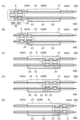
- FIGS. 5A to 5E are diagrams illustrating an example of the operation when the moving unit moves the vehicle.
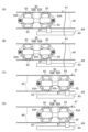
- 6(A) to 6(D) are diagrams illustrating another example of the operation when the moving unit moves the traveling vehicle.
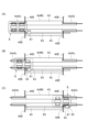
- FIGS. 7(A) to 7(C) are diagrams illustrating another example of the operation when the moving unit moves the traveling vehicle.
- the traveling vehicle system 1 uses an overhead traveling vehicle 6 (hereinafter referred to as traveling vehicle 6) that is movable along a traveling track 4 to place articles 10.
- traveling vehicle 6 This is a system for transporting between parts 9 and 9.
- the articles 10 include, for example, a FOUP (Front Opening Unified Pod) that stores a plurality of semiconductor wafers, a container that stores a glass substrate, a container such as a reticle pod, and general parts.
- the traveling vehicle system 1 includes a traveling track 4, a plurality of traveling vehicles 6, a plurality of mounting sections 9, a working track 41, and a moving unit 60.
- the running track 4 is laid, for example, near the ceiling, which is the space above the worker's head.
- the running track 4 is suspended from the ceiling, for example.
- the traveling track 4 is a predetermined traveling path on which the traveling vehicle 6 travels.
- the running track 4 is supported by struts 40A, 40A.
- the running track 4 of the running vehicle system 1 introduces the running vehicle 6 onto a working track 41 provided with a main line portion 4A that patrols a predetermined area in one direction and a work area 160 for maintaining the running vehicle 6. It has a retraction part 4B. Note that the traveling vehicle 6 also moves in one predetermined direction in the retraction section 4B.
- the running track 4 includes a cylindrical rail main body 40 consisting of a pair of lower surfaces 40B, 40B, a pair of side surfaces 40C, 40C, and a top surface 40D, a power supply line 40E, and a magnetic plate 40F. ing.
- the rail body portion 40 accommodates (includes) a traveling portion 50 of the traveling vehicle 6 .
- the lower surface portion 40B extends in the traveling direction of the traveling vehicle 6 and constitutes the lower surface of the rail main body portion 40.
- the lower surface portion 40B is a plate-like member on which the traveling rollers 51 of the traveling vehicle 6 roll.
- the side surface portion 40C extends in the traveling direction of the traveling vehicle 6 and constitutes a side surface of the rail body portion 40.
- the top surface portion 40D extends in the traveling direction of the traveling vehicle 6 and constitutes the upper surface of the rail body portion 40.
- the power supply line 40E is a part that supplies power to the power supply core 57 of the traveling vehicle 6 and transmits and receives signals to and from the power supply core 57.
- the power supply line 40E is fixed to each of the pair of side surfaces 40C, 40C, and extends along the running direction.
- the power supply line 40E supplies power to the power supply core 57 in a non-contact manner.
- the magnetic plate 40F generates a magnetic force for driving or stopping the LDM (Linear DC Motor) 59 of the traveling vehicle 6.
- the magnetic plate 40F is fixed to the top surface portion 40D and extends along the traveling direction.
- the traveling vehicle 6 travels on the traveling track 4 and conveys the article 10.
- the traveling vehicle 6 travels on the traveling track 4, it means that the traveling rollers 51 of the traveling vehicle 6 roll on the lower surface portion 40B of the traveling track 4.
- the traveling vehicle 6 is configured to be able to transfer the article 10 thereon.
- the traveling vehicle 6 is an unmanned vehicle that travels on the ceiling.
- the number of traveling vehicles 6 included in the traveling vehicle system 1 is not particularly limited, and is plural.
- the traveling vehicle 6 includes a main body portion 7, a traveling portion 50, and a traveling vehicle controller 35.
- the main body section 7 includes a main body frame 22, a transverse feed section 24, a ⁇ drive 26, an elevating drive section 28, an elevating table 30, and a cover 33.
- the main body frame 22 is connected to the traveling section 50 and supports the traversing section 24, the ⁇ drive 26, the elevating drive section 28, the elevating table 30, and the cover 33.
- the traversing section 24 collectively traverses the ⁇ drive 26, the elevating drive section 28, and the elevating platform 30 in a direction perpendicular to the traveling direction of the traveling track 4.
- the ⁇ drive 26 rotates at least one of the elevating drive unit 28 and the elevating table 30 within a predetermined angular range within a horizontal plane.
- the elevating and lowering drive section 28 raises and lowers the elevating platform 30 by winding or feeding out hanging materials such as wires, ropes, and belts.
- the elevating table 30 is provided with a chuck so that the article 10 can be gripped or released.
- a pair of covers 33 are provided at the front and rear of the vehicle 6 in the traveling direction.
- the cover 33 has claws (not shown) and the like to prevent the article 10 from falling during transportation.
- the traveling section 50 causes the traveling vehicle 6 to travel along the traveling track 4.
- the traveling portion 50 has two main bodies 50A and 50B, and the two main bodies 50A and 50B are connected to each other.
- each of the two main body parts 50A and 50B includes a running part 50, a running roller 51, a side roller 52, a branch roller (engaging part) 53, an auxiliary roller 54, an inclined roller 55, and a power supply. It has a core 57 and an LDM 59.
- illustration of the branch roller 53, the auxiliary roller 54, and the inclined roller 55 is omitted.
- the running rollers 51 are a roller pair consisting of an outer ring 51A as a running wheel and an inner ring 51B as a running auxiliary wheel.
- the running rollers 51 are arranged at both left and right ends of the front and back of the running section 50.
- the running rollers 51 roll on a pair of lower surface parts 40B, 40B of the running track 4 (or the lower support part 43 in FIG. 4, which will be described later).
- the side rollers 52 are arranged to sandwich each of the outer rings 51A of the running roller 51 in the front-rear direction.
- the side rollers 52 are provided so as to be able to come into contact with a side surface portion 40C of the traveling track 4 (or a side support portion 45 in FIG. 4, which will be described later).
- the branching roller 53 is provided to switch whether the traveling vehicle 6 (traveling section 50) travels straight or branches at a branching portion of the traveling track 4. More specifically, the branching roller 53 switches the running direction of the vehicle 6 by being guided by selectively contacting (abutting) a guide member provided at the branching portion.
- Four branching rollers 53 are provided for one main body portion 50A (50B) (see FIGS. 6(A) to 6(D)). Two or more branching rollers 53 are arranged in the traveling direction (one direction) of the traveling vehicle 6 at intervals less than or equal to the maximum moving distance D (see FIG. 3) of the moving block 61 in the moving mechanism 63.
- the branching rollers 53 that can be engaged with the moving block 61 are four branching rollers 53 arranged on the left side of the traveling vehicle 6.
- the branch roller 53 is provided so as to be movable in the left-right direction by a switching mechanism 53C.
- the branching roller 53 has a first position (see FIG. 6(B)) where it is engaged with a moving block 61, which will be described in detail later, and a second position (see FIG. 6(A)) where it is separated from the moving block 61. The position can be switched between.
- Each of the main body portion 50A and the main body portion 50B is provided with a switching mechanism 53C.
- Each of the switching mechanisms 53C has a support member 53A and a roller drive section 53B.
- the support member 53A supports the four branch rollers 53 and is provided movably in the left-right direction (width direction).
- the roller drive unit 53B moves the support member 53A in the left-right direction.
- the switching mechanism 53C moves the four branch rollers 53 in the left-right direction integrally by moving the support member 53A in the left-right direction.
- the driving of the roller drive unit 53B is controlled by the traveling vehicle controller 35 that receives a command from the area controller 90.
- the auxiliary rollers 54 are a group of three rollers provided before and after the running section 50.
- the auxiliary roller 54 prevents the LDM 59, power supply core 57, etc. from contacting the magnetic plate 40F disposed on the upper surface of the running track 4 when the running section 50 tilts back and forth during running due to acceleration or deceleration, etc. It is provided for.
- the inclined rollers 55 are provided at the four corners of the LDM 59.
- the inclined roller 55 is arranged in an inclined state from the front and rear directions.
- the inclined rollers 55 are provided to prevent the running section 50 from tilting due to centrifugal force when traveling through a curve section.
- the power feeding core 57 is arranged before and after the traveling section 50 so as to sandwich the LDM 59 in the left-right direction. Non-contact power supply and non-contact transmission and reception of various signals are performed between the power supply line 40E arranged on the running track 4 and the working track 41.
- the power supply core 57 exchanges signals with the traveling vehicle controller 35.
- the LDM 59 is provided before and after the running section 50.
- the LDM 59 generates magnetic force for running or stopping between it and a magnetic plate 40F arranged on the upper surface of the running track 4 using an electromagnet.
- the mounting section 9 is arranged along the traveling track 4 and is provided at a position where articles 10 can be delivered to and from the traveling vehicle 6.
- the mounting section 9 includes a buffer and a delivery port.
- the buffer is a placement section on which the article 10 is temporarily placed.
- the buffer is used to transfer the article 10 when the article 10 being conveyed by the traveling vehicle 6 cannot be transferred to the delivery port due to, for example, another article 10 being placed at the intended delivery port.
- This is a placement section where the item is temporarily placed.
- the delivery port is a loading port for delivering the article 10 to a semiconductor processing device (not shown) such as a cleaning device, a film forming device, a lithography device, an etching device, a heat treatment device, and a planarization device. Department.
- the processing device is not particularly limited, and may be any of various devices.
- the mounting section 9 is arranged on the side of the running track 4.
- the traveling vehicle 6 transfers the article 10 to and from the mounting section 9 by horizontally moving the elevating drive section 28 and the like using the transversely moving section 24 and slightly elevating and lowering the elevating table 30 .
- the mounting portion 9 may be placed directly below the running track 4. In this case, the traveling vehicle 6 transfers the article 10 to and from the mounting section 9 by raising and lowering the lifting platform 30.
- the vehicle controller 35 is an electronic control unit that includes a CPU (Central Processing Unit), a ROM (Read Only Memory), a RAM (Random Access Memory), and the like.
- the traveling vehicle controller 35 controls various operations in the traveling vehicle 6. Specifically, the traveling vehicle controller 35 controls the traveling section 50, the traverse section 24, the ⁇ drive 26, the elevation drive section 28, the elevator platform 30, and the roller drive section 53B.
- the vehicle controller 35 can be configured as software, for example, in which a program stored in a ROM is loaded onto a RAM and executed by a CPU.
- the vehicle controller 35 may be configured as hardware such as an electronic circuit.
- the traveling vehicle controller 35 communicates with the area controller 90 using a power supply line 40E such as a feeder line provided on the traveling track 4.
- the area controller 90 is an electronic control unit consisting of a CPU, ROM, RAM, etc.
- the area controller 90 can be configured as software, for example, in which a program stored in a ROM is loaded onto a RAM and executed by a CPU.
- the area controller 90 may be configured as hardware such as an electronic circuit.
- Area controller 90 transmits a transport command to cause traveling vehicle 6 to transport article 10 .
- the work area 160 is provided in a part of the retreat section 4B, and is an area where maintenance of the traveling rollers 51, power supply core 57, etc. of the traveling section 50 included in the traveling vehicle 6 is performed.
- the work area 160 is provided with a work track 41 (see FIG. 3) and a moving unit 60 (see FIGS. 5 and 6).
- the working track 41 extends in one direction (hereinafter referred to as the "extending direction") so that both ends thereof are continuous with the running tracks 4, 4, and as shown in FIGS. 3 and 4, An open portion 47 is formed that exposes at least a portion of the traveling portion 50 (for example, the power feeding core 57).
- the work track 41 is not provided with the side surface portions 40C and the top surface portion 40D that are provided on the travel track 4, nor is the magnetic plate 40F provided on the top surface portion 40D. Therefore, the traveling vehicle 6 cannot travel on the working track 41 by itself.
- the working track 41 forms a non-self-propelled section in which the traveling vehicle 6 cannot travel on its own.
- the running track 4 forms a self-running section in which the traveling vehicle 6 can run on its own.
- the work track 41 includes a frame 42 disposed at both ends of the work track 41, a pair of lower support parts 43, 43, a pair of side support parts 45, 45, and a power supply line 40E. There is.
- the frame 42 has a pair of column parts 42A, 42A and a horizontal part 42B.
- the pair of columnar parts 42A, 42A are columnar members arranged to face each other in the left-right direction and extend in the vertical direction.
- the horizontal portion 42B is fixed to the ceiling via a bracket (not shown) and a column (not shown).
- the horizontal portion 42B is a columnar member that connects the pair of columnar portions 42A, 42A at the upper ends of the pair of columnar portions 42A, 42A.
- the lower support part 43 supports the traveling part 50 from below. More specifically, the lower support portion 43 is a member that causes the inner ring 51B of the traveling roller 51 of the traveling vehicle 6 to roll and travel.
- the lower support portion 43 is fixed to the lower end of the column portion 42A of the frame 42.
- the lower support portion 43 is formed such that a first portion 43B facing the inner ring 51B is located above a second portion 43A facing the outer ring 51A in the vertical direction.
- the first portion 43B of the lower support portion 43 (that is, the rolling surface of the inner ring 51B) is at the same level as the upper surface of the lower surface portion 40B of the running track 4 (see FIG. 2) at the portion connected to the running track 4.
- the side support portion 45 is a member with which the side rollers 52 of the traveling vehicle 6 come into contact.
- the side support portion 45 is spanned between a pair of frames 42, 42.
- the power supply line 40E is spanned between a pair of frames 42, 42, and is arranged in an opening 47 on the side of the working track 41.
- a power feed line 40E provided on the work track 41 is connected to a power feed line 40E provided on the travel track 4. That is, the traveling vehicle 6 cannot run on its own on the work track 41, but can receive power supply.
- the moving unit 60 moves the traveling vehicle 6 along the extending direction (one direction) of the work track 41, which is a non-self-propelled section. Traveling tracks 4, 4 are connected to both ends of the working track 41.
- the moving unit 60 moves the traveling vehicle 6, which cannot self-propel, between one traveling track 4 and the other traveling track 4.
- the moving unit 60 includes a moving block 61 and a moving mechanism 63.
- the moving block 61 is a member that can engage the branching roller 53. More specifically, the moving block 61 is formed with a recess 61a into which the branching roller 53 can enter (engage).
- the moving unit 60 moves the branching roller 53 and thus the traveling section 50 integrally with the moving block 61 by moving the moving block 61 in which the branching roller 53 is engaged with the recess 61a.
- the moving mechanism 63 is a mechanism that moves the moving block 61 in the extending direction of the working track 41.
- the moving mechanism 63 is a linear motion mechanism (ball screw) having a screw shaft 63A, a nut 63B, a shaft drive section 63C, and a slide rail 63D.
- the screw shaft 63A is a long member having a thread groove formed on its outer circumferential surface and extending in one direction, and has one end connected to the shaft drive section 63C and the other end supported by the bearing section 63E.
- the screw shaft 63A is arranged so that its extending direction is substantially parallel to the extending direction of the working track 41.
- the nut 63B is a member that is screwed into the thread groove of the screw shaft 63A.
- the nut 63B moves along the direction of extension of the threaded shaft 63A, that is, the direction of extension of the working track 41, as the threaded shaft 63A is rotated.
- the nut 63B is slidably supported on the slide rail 63D.
- the shaft drive unit 63C is a motor, and its rotating shaft is connected to the screw shaft 63A.
- the drive of the shaft drive unit 63C is controlled by the area controller 90.
- the slide rail 63D supports a portion of the nut 63B from below so as to be slidable along the direction in which the working track 41 extends.
- the moving mechanism 63 is disposed on one of the pair of lower support parts 43, 43, and is supported from below by the left lower support part (support member) 43.
- the moving mechanism 63 is arranged in a part of the lower support part 43 that supports the vehicle 6 from below.
- a dedicated support member for supporting the mechanism 63 may be attached, and the moving mechanism 63 may be supported by the support member.
- the lower support portion 43 provided with the moving mechanism 63 may be provided with a cleaning device for cleaning the traveling vehicle 6 and a maintenance device such as a camera for inspecting each part of the traveling vehicle 6.
- the traveling vehicle 6 arrives at the work track 41 in response to a movement command from the area controller 90 to the work area 160 (work track 41).
- the working track 41 is not provided with the magnetic plate 40F, but the traveling vehicle 6 has at least a portion of the two main body parts 50A, 50B overlapping the magnetic plate 40F of the running track 4. If it is in position, it is possible to run.
- the traveling vehicle 6 stops with, for example, one main body portion 50A entering the work track 41.
- FIG. 5A and 5B the traveling vehicle 6 stops with, for example, one main body portion 50A entering the work track 41.
- the moving block 61 is waiting at a position to the side of the stopped vehicle 6 with one main body 50A entering the work track 41. More specifically, the moving block 61 is waiting on the side of the branching roller 53 in the front row of the traveling vehicle 6.
- the traveling vehicle 6 drives the roller drive section 53B of the switching mechanism 53C to move the support member 53A to the left. That is, the position of the branching roller 53 is switched from the second position where it is separated from the moving block 61 to the first position where it is engaged with the moving block 61. As a result, the branching roller 53 becomes engaged with the moving block 61.
- the moving mechanism 63 integrally moves the traveling vehicle 6 by moving the moving block 61, which is engaged with the branching roller 53 provided on the traveling vehicle 6, in the extending direction (one direction) of the work track 41. let The moving mechanism 63 moves the work track 41 to a predetermined position, for example. Maintenance equipment as described above is provided at a predetermined position, and predetermined maintenance is performed on the traveling vehicle 6. Thereafter, the moving mechanism 63 moves the moving block 61 to the end in the extending direction of the moving mechanism 63, as shown in FIG. 5(C).
- the traveling vehicle 6 drives the roller drive section 53B of the switching mechanism 53C to move the support member 53A to the right. That is, the position of the branching roller 53 is switched from the first position to the second position. As a result, the branching roller 53 is separated from the moving block 61, as shown in FIG. 6(D). Thereafter, as shown in FIG. 5(D), the moving mechanism 63 moves the moving block 61 in the opposite direction to the moving direction of the traveling vehicle 6, and moves the branching roller 53 disposed in the last row of the traveling vehicle 6. Stop on the side.
- the traveling vehicle 6 drives the roller drive unit 53B of the switching mechanism 53C to move the support member 53A to the left so that the branch roller 53 is engaged with the moving block 61. Make it. Thereafter, the moving mechanism 63 moves the traveling vehicle 6 until, for example, one main body portion 50A enters the traveling track 4, as shown in FIG. 5(E). As described above, the moving mechanism 63 of the present embodiment engages the branch roller (one engagement portion) 53 disposed in the front row of the traveling vehicle 6 with the moving block 61 to move the traveling vehicle 6 onto the working track. 41, the branching roller 53 (another engaging portion located downstream of the first engaging portion in one direction) disposed in the last row of the traveling vehicle 6 and the moving block 61 to move the vehicle 6 in one direction.
- the traveling vehicle 6 drives the roller drive section 53B of the switching mechanism 53C to move the support member 53A to the right. That is, the position of the branching roller 53 is switched from the first position to the second position. As a result, the branching roller 53 becomes separated from the moving block 61.
- the main body part 50A of the two main body parts 50A and 50B has advanced to a position where it overlaps the magnetic plate 40F of the running track 4, so the traveling vehicle 6 can move on its own. It is in a state.
- the traveling vehicle 6 leaves the work area 160 in response to a movement command from the area controller 90.
- the moving block 61 and the traveling vehicle 6 can be moved integrally by simply moving the moving block 61 in a state in which the branching roller 53 provided on the traveling vehicle 6 is engaged. can. Since the moving mechanism 63 only needs to move the moving block 61 in one direction, the configuration can be simplified. Moreover, since the configuration for engaging the branching roller 53 with the moving block 61 is provided on the traveling vehicle 6 side, the configuration on the moving mechanism 63 side can be simplified.
- the moving mechanism 63 is a linear motion mechanism (ball screw) including the screw shaft 63A and the shaft drive section 63C, so it has a simple configuration and can be moved in the direction in which the work track 41 extends.
- the moving block 61 can be moved.
- two or more branch rollers 53 are arranged in the traveling direction of the traveling vehicle 6 at an interval equal to or less than the maximum movement distance D of the moving block 61 in the linear motion mechanism, and After engaging the branching roller 53 in the front row and the moving block 61 to move the traveling vehicle 6 in the extending direction of the work track 41, the branching roller 53 in the last row and the moving block 61 are engaged. The vehicle 6 is moved in the direction in which the work track 41 extends. With this configuration, the vehicle 6 can be moved beyond the movable distance of the moving block 61. Thereby, the size of the moving mechanism 63 in the moving direction of the traveling vehicle 6 can be reduced.
- the branching roller 53 provided in the traveling vehicle 6 is engaged with the moving block 61 by switching the position of the branching roller 53 in the left-right direction.
- the members provided in the existing traveling vehicle 6 can be used as they are without the need to newly provide an engaging portion that engages with the moving block 61, so that manufacturing can be performed at low cost.
- the moving mechanism 63 is supported by the lower support part 43 attached to the work track 41, so that the supporting members supporting the moving mechanism 63 are individually suspended from the ceiling or the like. Compared to this, the number of installation steps can be significantly reduced.
- the traveling vehicle 6 of the traveling vehicle system 1 of the above embodiment is an overhead traveling vehicle that travels along the traveling track 4, and the working track 41 is suspended from the ceiling of the building or a mount installed on the ground. There is. With this configuration, it is possible to move the traveling vehicle 6 out of the reach of workers who work while standing on the ground of the building. This is highly effective because it saves the worker the trouble of preparing a stepladder or the like when manually moving the vehicle 6.
- the traveling vehicle 6 can be moved even if the working track 41 is not provided with the magnetic plate 40F. Thereby, in the working track 41, the top surface portion 40D on which the magnetic plate 40F is provided in the running track 4 can be opened, making it easier to perform maintenance on the upper part of the running section 50.
- the traveling vehicle 6 may be provided with a dedicated engaging member that can be engaged by the moving block 61.
- the engaging portion may be configured to be movable in the left-right direction or the vertical direction by the drive unit, and the drive unit may be configured to be controllable by the area controller 90. Even in this case, the same effects as in the above embodiment can be obtained.
- the working track 41 is provided with the power feed line 40E along the extending direction.
- the track (non-self-propelled section) 41 may have a configuration in which the power supply line 40E is not provided.
- the shaft drive section 63C that moves the engaging section in the left-right direction cannot be driven either. Therefore, as shown in FIG. 7(A), in the configuration of the traveling vehicle system 1 according to the modified example, the moving mechanism 63 is secured longer than the work track 41 in the traveling direction of the traveling vehicle 6, and the front row branch
- the moving block 61 that engages the roller 53 is configured to extend to the position of the traveling track 4. That is, in the configuration of the modified example, as shown in FIG. 7(C), the vehicle 6 is configured to be able to move beyond the range of the work track 41 in the traveling direction of the vehicle 6. .
- the traveling vehicle 6 When the traveling vehicle 6 is moved beyond the range of the work track 41, as shown in FIG. Since it overlaps with the power supply line 40E of the running track 4, it becomes possible to receive power supply, and it becomes possible to switch the position of the branching roller 53 in the left-right direction. Further, since the main body portion 50A, which is one of the two main body portions 50A and 50B of the traveling vehicle 6, overlaps with the magnetic plate 40F of the traveling track 4, the traveling vehicle 6 can run by itself. Even with the configuration according to such a modification, the traveling vehicle 6 can be moved on the work track 41 without the power supply line 40E. Further, in the work track 41, since the side surface 40C of the running track 4 where the power supply line 40E is provided can be opened, maintenance of the side surface of the running section 50 can be easily carried out.
- the working track 41 of the above embodiment has been described using an example in which the side of the traveling vehicle 6 is completely open, the wall portion (side surface portion) in which a hole into which the moving block 61 can be inserted is formed. It may have. Even in this case, since the moving block 61 can be moved in the extending direction of the work track 41 while the branching roller 53 is engaged, the traveling vehicle can be moved.
- the working area 160 (that is, the working track 41) has been described with reference to an example arranged between the running tracks 4, but the working area 160 is It may be arranged at the terminal end of the running track 4.
- the vehicle is applied to the traveling track 4 for suspending and running the traveling vehicle 6, but one aspect of the present invention is that the traveling vehicle runs on a track arranged on the ground. It can also be applied to a traveling vehicle system.
- a running track that forms a self-running section in which a running vehicle can run on its own; a work track forming a non-self-propelled section in which the traveling vehicle cannot self-propel; a traveling vehicle traveling along the traveling track; a moving unit that moves the traveling vehicle in one direction in the non-self-propelled section, The moving unit has a moving mechanism that moves the moving block in the one direction, The traveling vehicle is an engaging portion that can engage with the moving block; a switching mechanism that switches the position of the engaging portion between a first position where the engaging portion is engaged by the moving block and a second position where the engaging portion is separated from the moving block; The moving mechanism is a traveling vehicle system in which the traveling vehicle is moved by moving the moving block with the engaging portion engaged in the one direction.
- the running track is A branch and a plurality of guides that guide the traveling vehicle in respective directions branched at the branching portion; [1] to [3], wherein the engaging portion is a branching roller that switches the running direction of the vehicle at the branching portion by selectively abutting each of the guides at the branching portion.
- the traveling vehicle system described in any one of the above.
- the work track is suspended from the ceiling of the building or a pedestal installed on the ground,
- the traveling vehicle system according to any one of [1] to [5], wherein the traveling vehicle is an overhead traveling vehicle that transports articles by traveling along the work track.
- the traveling vehicle has a linear motor that runs by magnetic force generated between it and a magnetic plate provided on the traveling track, The traveling vehicle system according to any one of [1] to [6], wherein the working track is not provided with the magnetic plate.
- a power supply line that supplies power to the traveling vehicle is arranged on the traveling track, The traveling vehicle system according to any one of [1] to [7], wherein the power supply line is not provided on the work track.
- Switching mechanism 57 ...Power supply core, 60...Movement unit, 61...Movement block, 63...Movement mechanism, 63A...Screw shaft, 63B...Nut, 63C...Shaft drive section, 63D...Slide rail, 90...Area controller, 160...Work area.
Landscapes
- Engineering & Computer Science (AREA)
- Mechanical Engineering (AREA)
- Transportation (AREA)
- Chemical & Material Sciences (AREA)
- Combustion & Propulsion (AREA)
- Platform Screen Doors And Railroad Systems (AREA)
- Control Of Position, Course, Altitude, Or Attitude Of Moving Bodies (AREA)
Priority Applications (5)
| Application Number | Priority Date | Filing Date | Title |
|---|---|---|---|
| CN202380060193.7A CN119731067A (zh) | 2022-08-18 | 2023-06-20 | 行驶车系统 |
| US19/103,678 US20260048769A1 (en) | 2022-08-18 | 2023-06-20 | Traveling vehicle system |
| KR1020257004171A KR102919918B1 (ko) | 2022-08-18 | 2023-06-20 | 주행차 시스템 |
| EP23854709.5A EP4559774A1 (en) | 2022-08-18 | 2023-06-20 | Traveling vehicle system |
| JP2024541431A JPWO2024038671A1 (cg-RX-API-DMAC7.html) | 2022-08-18 | 2023-06-20 |
Applications Claiming Priority (2)
| Application Number | Priority Date | Filing Date | Title |
|---|---|---|---|
| JP2022-130661 | 2022-08-18 | ||
| JP2022130661 | 2022-08-18 |
Publications (1)
| Publication Number | Publication Date |
|---|---|
| WO2024038671A1 true WO2024038671A1 (ja) | 2024-02-22 |
Family
ID=89941439
Family Applications (1)
| Application Number | Title | Priority Date | Filing Date |
|---|---|---|---|
| PCT/JP2023/022791 Ceased WO2024038671A1 (ja) | 2022-08-18 | 2023-06-20 | 走行車システム |
Country Status (6)
| Country | Link |
|---|---|
| US (1) | US20260048769A1 (cg-RX-API-DMAC7.html) |
| EP (1) | EP4559774A1 (cg-RX-API-DMAC7.html) |
| JP (1) | JPWO2024038671A1 (cg-RX-API-DMAC7.html) |
| KR (1) | KR102919918B1 (cg-RX-API-DMAC7.html) |
| CN (1) | CN119731067A (cg-RX-API-DMAC7.html) |
| WO (1) | WO2024038671A1 (cg-RX-API-DMAC7.html) |
Cited By (1)
| Publication number | Priority date | Publication date | Assignee | Title |
|---|---|---|---|---|
| WO2025262650A1 (en) * | 2024-06-20 | 2025-12-26 | Anglo American Technical & Sustainability Services Ltd | External vehicle propulsion infrastructure |
Citations (3)
| Publication number | Priority date | Publication date | Assignee | Title |
|---|---|---|---|---|
| JP2010012972A (ja) * | 2008-07-04 | 2010-01-21 | Daifuku Co Ltd | スクリュー駆動の搬送台車装置 |
| JP2017088032A (ja) * | 2015-11-12 | 2017-05-25 | 株式会社ダイフク | 搬送装置 |
| WO2020202856A1 (ja) | 2019-04-03 | 2020-10-08 | 村田機械株式会社 | 走行車システム |
-
2023
- 2023-06-20 KR KR1020257004171A patent/KR102919918B1/ko active Active
- 2023-06-20 EP EP23854709.5A patent/EP4559774A1/en active Pending
- 2023-06-20 US US19/103,678 patent/US20260048769A1/en active Pending
- 2023-06-20 WO PCT/JP2023/022791 patent/WO2024038671A1/ja not_active Ceased
- 2023-06-20 CN CN202380060193.7A patent/CN119731067A/zh active Pending
- 2023-06-20 JP JP2024541431A patent/JPWO2024038671A1/ja active Pending
Patent Citations (3)
| Publication number | Priority date | Publication date | Assignee | Title |
|---|---|---|---|---|
| JP2010012972A (ja) * | 2008-07-04 | 2010-01-21 | Daifuku Co Ltd | スクリュー駆動の搬送台車装置 |
| JP2017088032A (ja) * | 2015-11-12 | 2017-05-25 | 株式会社ダイフク | 搬送装置 |
| WO2020202856A1 (ja) | 2019-04-03 | 2020-10-08 | 村田機械株式会社 | 走行車システム |
Cited By (1)
| Publication number | Priority date | Publication date | Assignee | Title |
|---|---|---|---|---|
| WO2025262650A1 (en) * | 2024-06-20 | 2025-12-26 | Anglo American Technical & Sustainability Services Ltd | External vehicle propulsion infrastructure |
Also Published As
| Publication number | Publication date |
|---|---|
| JPWO2024038671A1 (cg-RX-API-DMAC7.html) | 2024-02-22 |
| TW202421479A (zh) | 2024-06-01 |
| KR102919918B1 (ko) | 2026-01-28 |
| EP4559774A1 (en) | 2025-05-28 |
| CN119731067A (zh) | 2025-03-28 |
| KR20250034478A (ko) | 2025-03-11 |
| US20260048769A1 (en) | 2026-02-19 |
Similar Documents
| Publication | Publication Date | Title |
|---|---|---|
| TWI763871B (zh) | 搬運系統及搬運方法 | |
| TWI821552B (zh) | 行走車系統 | |
| WO2024038671A1 (ja) | 走行車システム | |
| US12522254B2 (en) | Overhead transport vehicle system | |
| TWI905483B (zh) | 高架搬運車系統 | |
| CN116605602A (zh) | 保管架及搬送车系统 | |
| TWI888826B (zh) | 高架搬送車 | |
| TWI922826B (zh) | 移行車系統 | |
| KR102637694B1 (ko) | 주행차 시스템 | |
| TW202546975A (zh) | 軌道設備及有軌道台車系統 | |
| JP2025151006A (ja) | 走行車システム | |
| WO2026088517A1 (ja) | 走行車システム | |
| TW202442557A (zh) | 有軌道台車系統 |
Legal Events
| Date | Code | Title | Description |
|---|---|---|---|
| 121 | Ep: the epo has been informed by wipo that ep was designated in this application |
Ref document number: 23854709 Country of ref document: EP Kind code of ref document: A1 |
|
| ENP | Entry into the national phase |
Ref document number: 20257004171 Country of ref document: KR Kind code of ref document: A |
|
| WWE | Wipo information: entry into national phase |
Ref document number: 1020257004171 Country of ref document: KR |
|
| WWE | Wipo information: entry into national phase |
Ref document number: 2024541431 Country of ref document: JP |
|
| WWE | Wipo information: entry into national phase |
Ref document number: 202380060193.7 Country of ref document: CN |
|
| WWE | Wipo information: entry into national phase |
Ref document number: 2023854709 Country of ref document: EP |
|
| ENP | Entry into the national phase |
Ref document number: 2023854709 Country of ref document: EP Effective date: 20250218 |
|
| WWP | Wipo information: published in national office |
Ref document number: 1020257004171 Country of ref document: KR |
|
| NENP | Non-entry into the national phase |
Ref country code: DE |
|
| WWE | Wipo information: entry into national phase |
Ref document number: 11202500991T Country of ref document: SG |
|
| WWP | Wipo information: published in national office |
Ref document number: 11202500991T Country of ref document: SG Ref document number: 202380060193.7 Country of ref document: CN |
|
| WWP | Wipo information: published in national office |
Ref document number: 2023854709 Country of ref document: EP |