WO2024033965A1 - トルクセンサのシール構造およびロボット - Google Patents
トルクセンサのシール構造およびロボット Download PDFInfo
- Publication number
- WO2024033965A1 WO2024033965A1 PCT/JP2022/030264 JP2022030264W WO2024033965A1 WO 2024033965 A1 WO2024033965 A1 WO 2024033965A1 JP 2022030264 W JP2022030264 W JP 2022030264W WO 2024033965 A1 WO2024033965 A1 WO 2024033965A1
- Authority
- WO
- WIPO (PCT)
- Prior art keywords
- torque sensor
- adapter
- axis
- ring
- torque
- Prior art date
- Legal status (The legal status is an assumption and is not a legal conclusion. Google has not performed a legal analysis and makes no representation as to the accuracy of the status listed.)
- Ceased
Links
Images







Classifications
-
- G—PHYSICS
- G01—MEASURING; TESTING
- G01L—MEASURING FORCE, STRESS, TORQUE, WORK, MECHANICAL POWER, MECHANICAL EFFICIENCY, OR FLUID PRESSURE
- G01L3/00—Measuring torque, work, mechanical power, or mechanical efficiency, in general
- G01L3/02—Rotary-transmission dynamometers
- G01L3/04—Rotary-transmission dynamometers wherein the torque-transmitting element comprises a torsionally-flexible shaft
- G01L3/10—Rotary-transmission dynamometers wherein the torque-transmitting element comprises a torsionally-flexible shaft involving electric or magnetic means for indicating
-
- G—PHYSICS
- G01—MEASURING; TESTING
- G01L—MEASURING FORCE, STRESS, TORQUE, WORK, MECHANICAL POWER, MECHANICAL EFFICIENCY, OR FLUID PRESSURE
- G01L5/00—Apparatus for, or methods of, measuring force, work, mechanical power, or torque, specially adapted for specific purposes
- G01L5/22—Apparatus for, or methods of, measuring force, work, mechanical power, or torque, specially adapted for specific purposes for measuring the force applied to control members, e.g. control members of vehicles, triggers
- G01L5/226—Apparatus for, or methods of, measuring force, work, mechanical power, or torque, specially adapted for specific purposes for measuring the force applied to control members, e.g. control members of vehicles, triggers to manipulators, e.g. the force due to gripping
Definitions
- the present disclosure relates to a support structure for a torque sensor and a robot.
- a torque detection device in which a sealing member is arranged between a housing surrounding a torque sensor (see, for example, Patent Document 1).
- an annular seal member is compressed by one casing that houses the reducer and another casing that fixes the torque sensor between the output shaft of the reducer.
- One aspect of the present disclosure is a reduction gear fixed between the fixed part and a first member, which includes a fixed part and a movable part rotatably supported around a predetermined axis with respect to the fixed part.
- a seal structure for a torque sensor wherein the torque sensor includes an annular seal member that detects torque around the axis and surrounds an outer periphery of the torque sensor, and the seal member includes a seal member that connects the fixing portion and the first member. This is the seal structure of the torque sensor compressed in the axial direction.
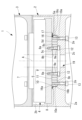
- FIG. 1 is a partial vertical cross-sectional view showing a robot according to a first embodiment of the present disclosure.
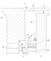
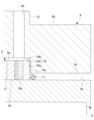
- FIG. 2 is a partially enlarged vertical cross-sectional view illustrating the seal structure of the torque sensor in the robot of FIG. 1;
- FIG. 2 is an exploded longitudinal cross-sectional view of a reduction gear, a torque sensor, and an O-ring in the robot of FIG. 1.
- FIG. FIG. 4 is an exploded longitudinal cross-sectional view showing the assembly and first member of the reducer, torque sensor, and O-ring of FIG. 3;
- FIG. 3 is a partially enlarged vertical cross-sectional view illustrating the assembly of the reducer, the torque sensor, and the first member in the seal structure of the torque sensor shown in FIG. 2;
- FIG. 6 is a partially enlarged vertical cross-sectional view showing a state in which the torque sensor starts to be fitted to the spigot part of the first member in FIG. 5;
- FIG. 6 is a partially enlarged vertical cross-sectional view showing a state in which the fitting between the spigot part and the torque sensor of FIG. 5 is completed;
- FIG. 5 is a longitudinal sectional view showing a state in which the assembly of FIG. 4 and the first member are assembled.
- FIG. 3 is a partial longitudinal sectional view showing a robot according to a second embodiment of the present disclosure.
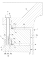
- 10 is a partially enlarged vertical sectional view illustrating the seal structure of the torque sensor in the robot of FIG. 9.
- FIG. 9 is a partially enlarged vertical cross-sectional view showing a state in which the torque sensor starts to be fitted to the spigot part of the first member in FIG. 5;
- FIG. 6 is a partially enlarged vertical cross-sectional view showing a state in which the fitting between the spigot part and the torque sensor of
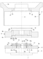
- FIG. 10 is an exploded longitudinal cross-sectional view showing the reducer, torque sensor, and O-ring assembly, adapter, O-ring, and base of the robot of FIG. 9.
- FIG. 11 is a partially enlarged vertical sectional view illustrating the assembly of the torque sensor and the adapter in the seal structure of the torque sensor of FIG. 10.
- FIG. 13 is a partially enlarged vertical cross-sectional view showing a state in which the torque sensor starts to be fitted into the spigot part of the adapter shown in FIG. 12;
- FIG. 13 is a partially enlarged vertical sectional view showing a state in which the fitting between the spigot part of the adapter shown in FIG. 12 and the torque sensor is completed;
- FIG. 12 is a longitudinal sectional view showing the assembled state of the assembly, adapter, O-ring, and base of FIG. 11;
- the robot 1 is, for example, a vertically articulated robot. As shown in FIG. 1, the robot 1 includes a first member 2 and a second member 3 rotatably supported around a first axis (axis) A with respect to the first member 2 at any joint. Be prepared.
- the first member 2 has a cylindrical shape with openings 2a and 2b opening on both sides in the first axis A direction.
- the first member 2 has a partition wall 2c that partitions the internal space in a direction along the first axis A.
- a speed reducer 4 is arranged between the first member 2 and the second member 3 to drive the second member 3 to rotate around the first axis A with respect to the first member 2 .
- Torque sensor 5 detects torque around the first axis A.
- the speed reducer 4 is formed in a cylindrical shape and includes a case (fixed part) 8 and an output part (movable part) 7 that is rotatably supported about the first axis A with respect to the case 8.
- the torque sensor 5 is fixed between the case 8 of the reducer 4 and the partition wall 2c of the first member 2.
- the torque sensor 5 is formed into a disk shape with an outer diameter smaller than that of the reducer 4.
- the torque sensor 5 includes a ring-shaped first portion 9 disposed radially inward and a ring-shaped second portion 10 disposed radially outward. Further, the torque sensor 5 includes a third portion 11 that connects the first portion 9 and the second portion 10.
- a sensor such as a strain gauge (not shown) is arranged in the third portion 11 to detect torque based on strain.
- the sensor may be placed close to either the first portion 9 or the second portion 10, or may be placed equidistant therefrom.
- the first portion 9 of the torque sensor 5 is provided with a plurality of through holes 9a that penetrate in the plate thickness direction and are spaced apart in the circumferential direction around the first axis A.
- the torque sensor 5 also includes a circular recess 5c centered on the first axis A on one end surface 5d of the first portion 9.
- the case 8 of the reducer 4 includes a convex portion 8b that fits into the concave portion 5c of the torque sensor 5, and an end surface 8c that brings the end surface 5d of the torque sensor 5 into close contact.
- the convex portion 8b of the case 8 and the concave portion 5c of the torque sensor 5 fit together with a very short fitting length, for example, 1 to 2 mm.
- the bolt 12 passed through the through hole 9a is fastened to the screw hole 8a with the protrusion 8b fitted into the recess 5c and the end surface 8c in close contact with the end surface 5d.
- the torque sensor 5 is fixed to the reduction gear 4.
- a plurality of screw holes 10a penetrating in the plate thickness direction are provided at intervals in the circumferential direction around the first axis A.
- the first member 2 includes a fitting portion 16 consisting of a circular recess into which the outer peripheral surface 5a of the torque sensor 5 is fitted.
- the fitting portion (recess) 16 includes an inner circumferential surface 16a that is disposed radially outward with a gap from the outer circumferential surface 5a of the torque sensor 5.
- the fitting portion 16 includes a bottom surface 16b against which the end surface 5b of the second portion 10 of the torque sensor 5 in the thickness direction abuts.
- the fitting part 16 includes a spigot part 16c that fits only one end of the outer circumferential surface 5a when the end surface 5b of the torque sensor 5 abuts against the bottom surface 16b.
- the fitting length of the pilot part 16c is set to be slightly larger than the appropriate crushing margin (compression amount) of the O-ring 17, which will be described later, but it is preferably as short as possible.
- the fitting length of the spigot part 16c is preferably greater than 0.7 mm and 2 mm or less.
- the first member 2 includes a plurality of through holes 2e that open in the bottom surface 16b of the fitting portion 16 and are spaced apart in the circumferential direction around the first axis A.
- the through hole 2e is provided at a position that matches the screw hole 10a when the outer circumferential surface 5a of the torque sensor 5 is fitted into the fitting portion 16.
- the bolt 13 passed through the through hole 2e of the first member 2 is fastened to the screw hole 10a of the torque sensor 5. Thereby, the torque sensor 5 can be fixed to the first member 2 with the bolt 13.
- the first member 2 has an end face (flat surface) 2f extending in a direction perpendicular to the first axis A, radially outward from the torque sensor 5. Further, the end surface (plane) 8c of the case 8 faces the end surface 2f of the first member 2 with a gap in the first axis A direction.
- An O-ring (sealing member) 17 is arranged between the end surface 2f of the first member 2 and the end surface 8c of the case 8.
- the gap between the end surface 2f of the first member 2 and the end surface 8c of the case 8 has a dimension that allows the O-ring 17 to be crushed with an appropriate crushing margin.
- the crushing allowance is the difference in wire diameter in the first axis A direction of the O-ring 17 when it is not crushed and when it is crushed.
- the O-ring 17 is crushed with an appropriate crushing amount to seal the gap so that liquid and gas cannot pass through.
- the O-ring 17 is formed in an annular shape surrounding the torque sensor 5, and has an inner diameter larger than the outer diameter of the outer circumferential surface 5a of the torque sensor 5 when it is not crushed, as shown in FIG. 4, for example. As shown in FIG. 2, the O-ring 17 has an inner diameter that does not contact or lightly contacts the outer circumferential surface 5a of the torque sensor 5 in the collapsed state. Thereby, the O-ring 17 is arranged at the edge around the fitting portion 16 (opening edge). The O-ring 17 seals the gap between the end surfaces 2f and 8c that contact the O-ring 17 from both sides in the first axis A direction.
- the first member 2, the torque sensor 5, and the reducer 4 are provided with a hollow hole 19 that communicates from the first member 2 to the inside of the rotating body 3 in a space that includes the first axis A.
- a filament (not shown) introduced from one side of the partition wall 2c of the first member 2 can be wired to the second member 3 side via the hollow hole 19.
- the seal structure of the torque sensor 5 and the operation of the robot 1 according to the present embodiment configured as described above will be described below.
- the robot 1 according to this embodiment is assembled as follows.
- the reducer 4 is arranged with the case 8 facing up and the first axis A being in the vertical direction. Then, the torque sensor 5 is brought close to the reducer 4 from above.
- the convex portion 8b of the case 8 is fitted into the concave portion 5c of the torque sensor 5, and the end surface 5d of the torque sensor 5 is brought into close contact with the end surface 8c of the case 8.
- the phase of the through hole 9a of the first portion 9 of the torque sensor 5 is adjusted to the phase of the screw hole 8a of the case 8. Then, as shown in FIG. 4, the bolt 12 passed through the through hole 9a of the first portion 9 of the torque sensor 5 is fastened to the screw hole 8a of the case 8. Thereby, the torque sensor 5 is fixed to the case 8 of the reduction gear 4 in a mutually positioned state in the first axis A direction and the direction perpendicular to the first axis A.
- an O-ring 17 is placed around the outer periphery of the torque sensor 5 fixed on the reduction gear 4, and placed on the end surface 8c of the case 8 radially outward of the outer circumferential surface 5a.
- the first member 2 is lowered from above the torque sensor 5.
- the torque sensor 5 is inserted into the fitting portion 16 of the first member 2. Then, as shown in FIG. 6, the outer peripheral surface 5a of the torque sensor 5 is fitted into the spigot part 16c near the bottom surface 16b of the fitting part 16.
- the fitting length of the torque sensor 5 to the spigot part 16c is set to be slightly larger than the appropriate crushing allowance of the O-ring 17. Therefore, as shown in FIG. 6, fitting of the torque sensor 5 to the spigot part 16c starts before the first member 2 contacts the O-ring 17.
- the outer peripheral surface 5a of the torque sensor 5 is fitted into the spigot part 16c.
- the O-ring 17 is crushed with an appropriate crushing margin.
- the torque sensor 5 is fixed to the first member 2. Then, the torque sensor 5 and the first member 2 are fixed in a mutually positioned state in the first axis A direction and in the direction orthogonal to the first axis A.
- the gap between the case 8 and the first member 2 becomes equal to the size of the O-ring 17 crushed with an appropriate crushing allowance.
- the gap between the case 8 and the first member 2 is sealed over the entire circumference by the O-ring 17 outside the torque sensor 5 in the radial direction.
- the fitting between the outer circumferential surface 5a of the torque sensor 5 and the first member 2 is achieved by the spigot part 16c having a sufficiently short fitting length.
- the gap between the case 8 of the reducer 4 and the first member 2 was sealed with an O-ring 17 on the radially outer side of the torque sensor 5. Thereby, liquid that has entered from the outside via the gap between the first member 2 and the second member 3 can be prevented from entering the torque sensor 5 side.
- the operator may not be able to recognize the start of fitting by touch. If the bolts 13 are fastened without being properly fitted, the fitting surfaces may be damaged or the parts may be assembled at an angle.
- the O-ring 17 is crushed between the end faces 2f and 8c perpendicular to the first axis A. Thereby, the sliding resistance of the O-ring 17 does not act during the operation of fitting the outer circumferential surface 5a of the torque sensor 5 into the recess 14 of the first member 2. Therefore, the operator can easily recognize the start of fitting by touch, and can properly assemble the parts.
- the O-ring 17 between the case 8 and the first member 2 is crushed on the radially outer side of the torque sensor 5.
- the crushed O-ring 17 does not come into contact with the outer circumferential surface 5a of the torque sensor 5, or only contacts it lightly.
- the force or moment that passes through the O-ring 17 does not have to act on the torque sensor 5. This can prevent the torque sensor 5 from detecting the force or moment acting on the torque sensor 5 via the O-ring 17 as torque.
- the robot 1 is a vertically articulated robot.
- the present invention may be applied to any other form of robot 1.
- the seal structure of the torque sensor 5 provided between the first member 2 and the second member 3 is illustrated.
- first member 2 for example, a rotating trunk can be applied
- second member 3 for example, a first arm can be applied
- a similar structure may be employed as a seal structure for a torque sensor disposed between the reducer and the first member of another joint shaft.
- the O-ring 17 is used as the sealing member, any other sealing member such as a ring-shaped gasket may be used instead.
- the radial position of the O-ring 17 is roughly guided by the outer peripheral surface 5a of the torque sensor 5.
- an O-ring groove may be formed in the case 8 or the first member 2 to define the radial position of the O-ring 17.
- the torque sensor 5 can accurately detect the torque acting on the first member 2 from the speed reducer 4. Further, according to the robot 1 according to the present disclosure, force control can be performed accurately due to the seal structure of the torque sensor 5 that can accurately detect torque.
- the case where the torque sensor 5 is directly fixed to the first member 2 has been described as an example. Instead, in this embodiment, as shown in FIG. 9, a case will be described in which the torque sensor 5 is fixed to the first member 2 with an adapter 6 interposed therebetween.
- the first member 2 is a base and the second member 3 is a rotating trunk. Hereinafter, it will also be referred to as the base 2 and the rotating body 3.
- the adapter 6 is made of a material that is more rigid than the material that makes up the base 2, and is formed into a disk shape that is larger radially outward than the torque sensor 5.
- the adapter 6 is preferably made of, for example, iron.
- the adapter 6 is provided with a plurality of through holes 6a that penetrate in the thickness direction and are spaced apart in the circumferential direction.
- the adapter 6 is fixed to the torque sensor 5 by fastening the bolt 13 passed through the through hole 6a to the screw hole 10a of the second portion 10.
- the adapter 6 has an outer diameter that is sufficiently larger than the outer diameter of the torque sensor 5. That is, the adapter 6 extends further radially outward beyond the outer peripheral surface 5a of the torque sensor 5. In the example shown in FIG. 9, the outer diameter of the adapter 6 is equivalent to the outer diameter of the reducer 4.
- the adapter 6 has a size that covers the entire area of the torque sensor 5 in the radial direction. That is, the adapter 6 has a size that extends inward in the radial direction of the second portion 10 of the torque sensor 5 necessary for fixation. Further, the adapter 6 has a thickness that is sufficiently larger than the thickness of the torque sensor 5. Thereby, the adapter 6 has sufficient rigidity to suppress deformation of the first member 2.
- the adapter 6 includes a first fitting portion 15 that is a circular convex portion that fits into a circular concave portion 14 provided in the first member 2 with the first axis A as the center.
- a fitting part hereinafter referred to as a second fitting part 16 is provided in the adapter 6.
- the outer diameter of the convex portion that constitutes the first fitting portion 15 and the inner diameter of the recessed portion that constitutes the second fitting portion 16 are set to be approximately equal.
- the through hole 6a is provided at a position that matches the screw hole 10a when the outer circumferential surface 5a of the torque sensor 5 is fitted into the second fitting portion 16. Furthermore, the through hole 2e of the base 2 is provided at a position that coincides with the through hole 6a when the first fitting portion 15 of the adapter 6 is fitted into the recess 14.
- the bolt 13 passed through the through hole 2e of the base 2 and the through hole 6a of the adapter 6 is fastened to the screw hole 10a of the torque sensor 5.
- the torque sensor 5 and the adapter 6 can be fixed to the base 2 by tightening the bolts 13 together.
- the outer portion of the adapter 6 that is radially outward than the torque sensor 5 has parallel end surfaces (planes) 6b and 6c perpendicular to the thickness direction on both sides in the thickness direction.
- the end surface 2f of the base 2 faces the end surface 6b of the adapter 6 with a gap in the first axis A direction.
- the end surface 8c of the case 8 of the reducer 4 faces the end surface 6c of the adapter 6 with a gap in the first axis A direction.
- the O-ring (second sealing member) 18 is formed in an annular shape surrounding the first fitting portion 15 and is disposed between the end surface 2f of the base 2 and the end surface 6b of the adapter 6. Further, an O-ring 17 is arranged between the end surface 8c of the case 8 of the reducer 4 and the end surface 6c of the adapter 6.
- the gap between the end surface 2f of the base 2 and the end surface 6b of the adapter 6 has a dimension that allows the O-ring 18 to be crushed with an appropriate crushing margin. Further, the gap between the flat surface 8c of the case 8 and the flat surface 6c of the adapter 6 has a dimension that allows the O-ring 17 to be crushed with an appropriate crushing margin.
- the O-rings 17 and 18 are crushed with an appropriate crushing amount to seal the gap to prevent liquid and gas from passing through.
- the O-ring 17 seals the gap between the flat surfaces 6c and 8c that contact the O-ring 17 from both sides in the first axis A direction.
- the O-ring 18 is compressed in the direction of the axis A between end surfaces 2f and 6b that contact the O-ring 18 from both sides in the direction of the first axis A, thereby sealing the gap.
- the adapter 6 also includes a hollow hole 19 that communicates with the space including the first axis A from the base 2 to the inside of the rotating body 3.
- the seal structure of the torque sensor 5 and the operation of the robot 1 according to the present embodiment configured as described above will be described below.
- the robot 1 according to this embodiment is assembled as follows. First, the assembly of the reducer 4, torque sensor 5, and O-ring 17 is the same as in the first embodiment.
- the fitting length of the torque sensor 5 into the spigot part 16c is set to be slightly larger than the appropriate crushing allowance of the O-ring 17. Therefore, as shown in FIG. 13, fitting of the torque sensor 5 to the spigot part 16c starts before the adapter 6 contacts the O-ring 17. By bringing the adapter 6 into contact with the O-ring 17 after the start of fitting, the operator can more reliably recognize the start of fitting, and the workability of the assembly work is improved.
- the outer peripheral surface 5a of the torque sensor 5 is fitted into the spigot part 16c.
- the O-ring 17 is crushed with an appropriate crushing margin. In this state, the phases of the through hole 6a of the adapter 6 and the screw hole 10a of the torque sensor 5 are aligned.
- the O-ring 18 is placed on the radially outer end surface 6b of the first fitting portion 15 of the adapter 6. Then, as shown in FIG. 11, the base 2 is brought close to the adapter 6 from above, and the first fitting part 15 of the adapter 6 is fitted into the recess 14 of the base 2.
- the torque sensor 5 and the adapter 6 are fixed to the base 2 by tightening them together. Then, the torque sensor 5, the adapter 6, and the base 2 are fixed in a mutually positioned state in the first axis A direction and the direction orthogonal to the first axis A.
- the torque sensor 5 and the adapter 6 and the adapter 6 and the base 2 can be fixed at the same distance in the radial direction. Compared to the case where the fixed distances differ in the radial direction, the torque sensor 5 can be made less susceptible to the influence of moments generated around an axis perpendicular to the first axis A.
- the gaps between the case 8 and the adapter 6 and between the base 2 and the adapter 6 become equal to the dimensions obtained by crushing the O-rings 17 and 18 with an appropriate crushing allowance.
- the gap between the case 8 of the reducer 4 and the adapter 6 is sealed over the entire circumference by the O-ring 17 radially outward of the torque sensor 5.
- the gap between the base 2 and the adapter 6 is also sealed over the entire circumference by an O-ring 18 radially outward of the first fitting portion 15 of the adapter 6.
- the torque sensor 5 is fixed to the base 2 with the adapter 6 interposed.
- the adapter 6 is made of a material that is more rigid than the base 2. Furthermore, the adapter 6 is thick and has a shape that extends not only to the second portion 10 of the torque sensor 5 to which it is fixed, but also to the outside and outside in the radial direction.
- the adapter 6 has sufficiently high rigidity, and deformation of the base 2 at the bottom surface of the recess 14 to which the adapter 6 is fixed can be sufficiently suppressed. That is, deformation of the base 2 due to force or torque applied to the torque sensor 5 from the speed reducer 4 side can be suppressed, and detection accuracy by the torque sensor 5 can be improved.
- the fitting between the outer peripheral surface 5a of the torque sensor 5 and the adapter 6 is achieved by the spigot part 16c having a sufficiently small fitting length.
- the gap between the case 8 of the reducer 4 and the adapter 6 was sealed with an O-ring 17 on the radially outer side of the torque sensor 5. Thereby, liquid that has entered from the outside via the gap between the base 2 and the rotating body 3 can be prevented from entering the torque sensor 5 side.
- the gap between the adapter 6 and the base 2 was also sealed with an O-ring 18. Thereby, liquid that has entered from the outside via the gap between the base 2 and the rotating body 3 can be prevented from entering further inward in the radial direction than the adapter 6.
- Another method of preventing liquid from entering through the gap between the base 2 and the rotating body 3 is to seal the cylindrical gap between the speed reducer 4 and the base 2. According to this, one O-ring is sufficient.
- the O-ring 17 is crushed between the planes 6c and 8c perpendicular to the first axis A. Thereby, during the operation of fitting the first fitting part 15 of the adapter 6 into the recess 14 of the base 2, the sliding resistance of the O-ring 17 does not act. Therefore, the operator can easily recognize the start of fitting by touch, and can properly assemble the parts.
- the O-ring 17 is crushed by being compressed in the direction of the axis A between the case 8 and the adapter 6 on the radially outer side of the torque sensor 5. This can prevent the torque sensor 5 from detecting the force or moment acting on the torque sensor 5 via the O-ring 17 as torque.
- the base 2, adapter 6, and torque sensor 5 are fixed at the same distance around the first axis A by tightening them together.
- the base 2 and the adapter 6 and the adapter 6 and the torque sensor 5 may be fixed separately at the same distance around the first axis A.
- the adapter 6 and the torque sensor 5 can be fixed in advance. Thereby, the torque sensor 5 and the adapter 6 can be managed as a unit.
- the base 2 and the adapter 6 may be fixed radially outward of the torque sensor 5.
- the size of the bolts 13 can be increased and the number of bolts 13 can be reduced.
- O-rings 17 and 18 are used as sealing members, any other sealing member such as a ring-shaped gasket may be used instead. Further, in the present embodiment, the radial positions of the O-rings 17 and 18 are roughly guided by the inner outer circumferential surface 5a or the first fitting portion 15. Alternatively, O-ring grooves may be formed in the adapter 6, the case 8, or the base 2 to define the radial positions of the O-rings 17 and 18.
- the adapter 6 one that has sufficiently higher rigidity than the base 2 and can suppress deformation of the base 2 is exemplified.
- the base 2 has high rigidity
- an adapter 6 with low rigidity may be used.
Landscapes
- Physics & Mathematics (AREA)
- General Physics & Mathematics (AREA)
- Manipulator (AREA)
- Retarders (AREA)
Abstract
Description
本実施形態に係るロボット1は、例えば、垂直多関節型ロボットである。ロボット1は、図1に示すように、任意の関節に、第1部材2と、第1部材2に対して第1軸線(軸線)A回りに回転可能に支持される第2部材3とを備える。
これにより、Oリング17は、嵌合部16の周囲の縁部(開口縁部)に配置される。そして、Oリング17は、Oリング17に第1軸線A方向の両側から接触する端面2f,8cとの間において隙間を密封する。
本実施形態に係るロボット1は、以下の通りに組み立てられる。
また、本実施形態においては、第1部材2と第2部材3との間に設けられたトルクセンサ5のシール構造を例示した。
また、本実施形態においては、Oリング17の径方向位置を、トルクセンサ5の外周面5aによって大まかに案内した。これに代えて、ケース8あるいは第1部材2に、Oリング溝を形成し、Oリング17の径方向位置を規定してもよい。
本実施形態の説明において、上述した第1の実施形態と構成を共通とする箇所には同一符号を付して説明を省略する。
すなわち、アダプタ6は、固定に必要なトルクセンサ5の第2部分10の径方向内方にも広がる大きさを有する。また、アダプタ6は、トルクセンサ5の厚さよりも十分に大きな厚さ寸法を有する。これにより、アダプタ6は、第1部材2の変形を抑制するのに十分な剛性を確保している。
また、ベース2の貫通孔2eは、凹部14にアダプタ6の第1嵌合部15を嵌合させたときに、貫通孔6aに一致する位置に設けられている。
Oリング17は、Oリング17に第1軸線A方向の両側から接触する平面6c,8cとの間において隙間を密封する。Oリング18は、Oリング18に第1軸線A方向の両側から接触する端面2f,6bとの間において軸線A方向に圧縮されることによって隙間を密封する。
アダプタ6も、第1軸線Aを含む空間にベース2から旋回胴3の内部まで連通する中空孔19を備える。
本実施形態に係るロボット1は、以下の通りに組み立てられる。
まず、減速機4、トルクセンサ5およびOリング17までの組立は、第1の実施形態と同様である。
嵌合の開始後にアダプタ6をOリング17に接触させることにより、作業者が嵌合の開始をより確実に認識でき、組立作業の作業性が向上する。
また、本実施形態においては、Oリング17,18の径方向位置を、内側の外周面5aあるいは第1嵌合部15によって大まかに案内した。これに代えて、アダプタ6、ケース8あるいはベース2に、Oリング溝を形成し、Oリング17,18の径方向位置を規定してもよい。
2 第1部材(ベース)
3 第2部材(旋回胴)
4 減速機
5 トルクセンサ
5a 外周面
6 アダプタ
7 出力部(可動部)
8 ケース(固定部)
16 嵌合部(凹部)
16a 内周面
17 Oリング(シール部材)
18 Oリング(第2のシール部材)
A 第1軸線(軸線)
Claims (6)
- 固定部と該固定部に対して所定の軸線回りに回転可能に支持された可動部とを備える減速機の前記固定部と、第1部材との間に固定されたトルクセンサのシール構造であって、
前記トルクセンサが、前記軸線回りのトルクを検出し、
前記トルクセンサの外周を取り囲む環状のシール部材を備え、
該シール部材が、前記固定部と前記第1部材とにより、前記軸線方向に圧縮されているトルクセンサのシール構造。 - 前記トルクセンサが円板状に形成され、
前記固定部または前記第1部材の一方に、前記トルクセンサの外周面の径方向外方に隙間を空けて配置される内周面を有する凹部が設けられ、
前記シール部材が、前記凹部の開口縁部において圧縮されている請求項1に記載のトルクセンサのシール構造。 - 固定部と該固定部に対して所定の軸線回りに回転可能に支持された可動部とを備える減速機の前記固定部と、第1部材との間に固定されたトルクセンサのシール構造であって、
前記トルクセンサが、アダプタを介在させて前記第1部材に固定されるとともに、前記軸線回りのトルクを検出し、
前記トルクセンサの外周を取り囲む環状のシール部材を備え、
該シール部材が、前記固定部と前記アダプタとにより、前記軸線方向に圧縮されているトルクセンサのシール構造。 - 前記トルクセンサが円板状に形成され、
前記固定部または前記アダプタの一方に、前記トルクセンサの外周面の径方向外方に隙間を空けて配置される内周面を有する凹部が設けられ、
前記シール部材が、前記凹部の開口縁部において圧縮されている請求項3に記載のトルクセンサのシール構造。 - 環状の第2のシール部材を備え、
該第2のシール部材が、前記第1部材と前記アダプタとにより、前記軸線方向に圧縮されている請求項3または請求項4に記載のトルクセンサのシール構造。 - 第1部材と、
第2部材と、
前記第1部材に対して前記第2部材を所定の軸線回りに回転可能に支持する減速機と、
前記減速機と前記第1部材との間に固定され、前記軸線回りのトルクを検出するトルクセンサと、
該トルクセンサの外周を取り囲む環状のシール部材とを備え、
前記減速機が、前記トルクセンサを固定する固定部と該固定部に対して前記軸線回りに回転可能に支持された可動部とを備え、
該シール部材が、前記固定部と前記第1部材とにより、前記軸線方向に圧縮されているロボット。
Priority Applications (5)
| Application Number | Priority Date | Filing Date | Title |
|---|---|---|---|
| PCT/JP2022/030264 WO2024033965A1 (ja) | 2022-08-08 | 2022-08-08 | トルクセンサのシール構造およびロボット |
| DE112022007264.4T DE112022007264T5 (de) | 2022-08-08 | 2022-08-08 | Dichtungsstruktur für einen Drehmomentsensor und Roboter |
| JP2024540083A JP7751117B2 (ja) | 2022-08-08 | 2022-08-08 | トルクセンサのシール構造およびロボット |
| CN202280098718.1A CN119654540A (zh) | 2022-08-08 | 2022-08-08 | 扭矩传感器的密封结构以及机器人 |
| TW112128918A TW202421397A (zh) | 2022-08-08 | 2023-08-01 | 扭矩感測器的密封結構以及機器人 |
Applications Claiming Priority (1)
| Application Number | Priority Date | Filing Date | Title |
|---|---|---|---|
| PCT/JP2022/030264 WO2024033965A1 (ja) | 2022-08-08 | 2022-08-08 | トルクセンサのシール構造およびロボット |
Publications (1)
| Publication Number | Publication Date |
|---|---|
| WO2024033965A1 true WO2024033965A1 (ja) | 2024-02-15 |
Family
ID=89851164
Family Applications (1)
| Application Number | Title | Priority Date | Filing Date |
|---|---|---|---|
| PCT/JP2022/030264 Ceased WO2024033965A1 (ja) | 2022-08-08 | 2022-08-08 | トルクセンサのシール構造およびロボット |
Country Status (5)
| Country | Link |
|---|---|
| JP (1) | JP7751117B2 (ja) |
| CN (1) | CN119654540A (ja) |
| DE (1) | DE112022007264T5 (ja) |
| TW (1) | TW202421397A (ja) |
| WO (1) | WO2024033965A1 (ja) |
Citations (5)
| Publication number | Priority date | Publication date | Assignee | Title |
|---|---|---|---|---|
| JP2018173343A (ja) * | 2017-03-31 | 2018-11-08 | セイコーエプソン株式会社 | 力検出装置およびロボット |
| US20200086479A1 (en) * | 2018-09-13 | 2020-03-19 | Kinova Inc. | Articulated mechanism with compact torque sensor |
| CN210678773U (zh) * | 2019-09-30 | 2020-06-05 | 深圳市优必选科技股份有限公司 | 集成关节及机器人 |
| WO2021187332A1 (ja) * | 2020-03-18 | 2021-09-23 | ファナック株式会社 | 力センサを備えた回転軸構造及びロボット |
| JP2022052789A (ja) * | 2020-09-24 | 2022-04-05 | アズビル株式会社 | トルク検出装置 |
-
2022
- 2022-08-08 JP JP2024540083A patent/JP7751117B2/ja active Active
- 2022-08-08 CN CN202280098718.1A patent/CN119654540A/zh active Pending
- 2022-08-08 WO PCT/JP2022/030264 patent/WO2024033965A1/ja not_active Ceased
- 2022-08-08 DE DE112022007264.4T patent/DE112022007264T5/de active Pending
-
2023
- 2023-08-01 TW TW112128918A patent/TW202421397A/zh unknown
Patent Citations (5)
| Publication number | Priority date | Publication date | Assignee | Title |
|---|---|---|---|---|
| JP2018173343A (ja) * | 2017-03-31 | 2018-11-08 | セイコーエプソン株式会社 | 力検出装置およびロボット |
| US20200086479A1 (en) * | 2018-09-13 | 2020-03-19 | Kinova Inc. | Articulated mechanism with compact torque sensor |
| CN210678773U (zh) * | 2019-09-30 | 2020-06-05 | 深圳市优必选科技股份有限公司 | 集成关节及机器人 |
| WO2021187332A1 (ja) * | 2020-03-18 | 2021-09-23 | ファナック株式会社 | 力センサを備えた回転軸構造及びロボット |
| JP2022052789A (ja) * | 2020-09-24 | 2022-04-05 | アズビル株式会社 | トルク検出装置 |
Also Published As
| Publication number | Publication date |
|---|---|
| DE112022007264T5 (de) | 2025-03-27 |
| TW202421397A (zh) | 2024-06-01 |
| JPWO2024033965A1 (ja) | 2024-02-15 |
| CN119654540A (zh) | 2025-03-18 |
| JP7751117B2 (ja) | 2025-10-07 |
Similar Documents
| Publication | Publication Date | Title |
|---|---|---|
| JP6527734B2 (ja) | 固定装置、蒸気タービン、回転機械の製造方法及び組立方法 | |
| JPH04231775A (ja) | 分割メカニカル端面シール | |
| KR20180123433A (ko) | 스크롤 압축기 | |
| JPH07190013A (ja) | 旋回モータ及びその組み立て方法 | |
| US5294132A (en) | Semi-cartridge seal | |
| WO2024033965A1 (ja) | トルクセンサのシール構造およびロボット | |
| WO2024033962A1 (ja) | トルクセンサの支持構造およびロボット | |
| US20230235816A1 (en) | Drive having a housing, adapter plate, and cover hood | |
| JP7464641B2 (ja) | 減速機の防水構造、及び、回転装置 | |
| US20160116070A1 (en) | Mechanical seal having a precisely positioned bandage | |
| JP2526753Y2 (ja) | トルクセンサ付きメカニカルシール | |
| JP6847804B2 (ja) | 軸封装置及び軸封装置の組み立て方法 | |
| JP2018080795A (ja) | 分割型メカニカルシール | |
| JP3127076B2 (ja) | アウトサイド型メカニカルシール装置 | |
| KR20240031025A (ko) | 공작 기계 | |
| CN108026878B (zh) | 高压燃料泵 | |
| US12429120B2 (en) | Waterproof structure and robot | |
| JPS6320878Y2 (ja) | ||
| JP2006077835A (ja) | シール装置 | |
| JP4698237B2 (ja) | 管の挿口突部の形成方法 | |
| JPH0735143Y2 (ja) | 油圧固定フランジ | |
| JP4671109B2 (ja) | スクロール式流体機械 | |
| JP2547923Y2 (ja) | メカニカルシール | |
| WO2020170903A1 (ja) | タービンロータの固定装置、これを備えたタービンモジュール、及びタービンモジュールの輸送方法 | |
| JP2003314701A (ja) | 分割形メカニカルシール |
Legal Events
| Date | Code | Title | Description |
|---|---|---|---|
| 121 | Ep: the epo has been informed by wipo that ep was designated in this application |
Ref document number: 22954887 Country of ref document: EP Kind code of ref document: A1 |
|
| WWE | Wipo information: entry into national phase |
Ref document number: 2024540083 Country of ref document: JP |
|
| WWE | Wipo information: entry into national phase |
Ref document number: 112022007264 Country of ref document: DE |
|
| WWE | Wipo information: entry into national phase |
Ref document number: 202280098718.1 Country of ref document: CN |
|
| WWP | Wipo information: published in national office |
Ref document number: 202280098718.1 Country of ref document: CN |
|
| WWP | Wipo information: published in national office |
Ref document number: 112022007264 Country of ref document: DE |
|
| 122 | Ep: pct application non-entry in european phase |
Ref document number: 22954887 Country of ref document: EP Kind code of ref document: A1 |