WO2024029601A1 - 送風装置 - Google Patents
送風装置 Download PDFInfo
- Publication number
- WO2024029601A1 WO2024029601A1 PCT/JP2023/028464 JP2023028464W WO2024029601A1 WO 2024029601 A1 WO2024029601 A1 WO 2024029601A1 JP 2023028464 W JP2023028464 W JP 2023028464W WO 2024029601 A1 WO2024029601 A1 WO 2024029601A1
- Authority
- WO
- WIPO (PCT)
- Prior art keywords
- air
- intake port
- ultraviolet
- ultraviolet irradiation
- outside air
- Prior art date
- Legal status (The legal status is an assumption and is not a legal conclusion. Google has not performed a legal analysis and makes no representation as to the accuracy of the status listed.)
- Ceased
Links
Images


Classifications
-
- B—PERFORMING OPERATIONS; TRANSPORTING
- B60—VEHICLES IN GENERAL
- B60H—ARRANGEMENTS OF HEATING, COOLING, VENTILATING OR OTHER AIR-TREATING DEVICES SPECIALLY ADAPTED FOR PASSENGER OR GOODS SPACES OF VEHICLES
- B60H3/00—Other air-treating devices
- B60H3/0071—Electrically conditioning the air, e.g. by ionizing
- B60H3/0078—Electrically conditioning the air, e.g. by ionizing comprising electric purifying means
-
- B—PERFORMING OPERATIONS; TRANSPORTING
- B60—VEHICLES IN GENERAL
- B60H—ARRANGEMENTS OF HEATING, COOLING, VENTILATING OR OTHER AIR-TREATING DEVICES SPECIALLY ADAPTED FOR PASSENGER OR GOODS SPACES OF VEHICLES
- B60H3/00—Other air-treating devices
- B60H3/06—Filtering
- B60H3/0608—Filter arrangements in the air stream
-
- B—PERFORMING OPERATIONS; TRANSPORTING
- B60—VEHICLES IN GENERAL
- B60H—ARRANGEMENTS OF HEATING, COOLING, VENTILATING OR OTHER AIR-TREATING DEVICES SPECIALLY ADAPTED FOR PASSENGER OR GOODS SPACES OF VEHICLES
- B60H1/00—Heating, cooling or ventilating devices
- B60H1/00642—Control systems or circuits; Control members or indication devices for heating, cooling or ventilating devices
- B60H1/00664—Construction or arrangement of damper doors
-
- B—PERFORMING OPERATIONS; TRANSPORTING
- B60—VEHICLES IN GENERAL
- B60H—ARRANGEMENTS OF HEATING, COOLING, VENTILATING OR OTHER AIR-TREATING DEVICES SPECIALLY ADAPTED FOR PASSENGER OR GOODS SPACES OF VEHICLES
- B60H1/00—Heating, cooling or ventilating devices
- B60H1/00007—Combined heating, ventilating, or cooling devices
- B60H1/00021—Air flow details of HVAC devices
- B60H2001/00078—Assembling, manufacturing or layout details
- B60H2001/00085—Assembling, manufacturing or layout details of air intake
-
- F—MECHANICAL ENGINEERING; LIGHTING; HEATING; WEAPONS; BLASTING
- F24—HEATING; RANGES; VENTILATING
- F24F—AIR-CONDITIONING; AIR-HUMIDIFICATION; VENTILATION; USE OF AIR CURRENTS FOR SCREENING
- F24F8/00—Treatment, e.g. purification, of air supplied to human living or working spaces otherwise than by heating, cooling, humidifying or drying
- F24F8/20—Treatment, e.g. purification, of air supplied to human living or working spaces otherwise than by heating, cooling, humidifying or drying by sterilisation
- F24F8/22—Treatment, e.g. purification, of air supplied to human living or working spaces otherwise than by heating, cooling, humidifying or drying by sterilisation using UV light
Definitions
- the present disclosure relates to an air blower.
- a vehicle air conditioner is installed inside the dashboard of a vehicle to adjust the temperature of the air inside the vehicle.
- a vehicle air conditioner is an HVAC unit (Heating Ventilation and Air Conditioning Unit) that adjusts the temperature of air outside the vehicle (hereinafter referred to as "outside air") or air inside the vehicle (hereinafter referred to as “inside air”) and blows it into the vehicle interior. ) and a blower unit that supplies outside air or inside air to the HVAC unit.
- HVAC unit Heating Ventilation and Air Conditioning Unit
- the blower unit may be equipped with a device that inactivates microorganisms and viruses that adhere to particles floating in the air by irradiating the circulating air with ultraviolet rays.
- a device that inactivates microorganisms and viruses that adhere to particles floating in the air by irradiating the circulating air with ultraviolet rays.
- particles floating in the air are irradiated with ultraviolet rays, there is a possibility that microorganisms and viruses cannot be suitably inactivated unless the air is circulated and the ultraviolet rays are repeatedly irradiated.
- Patent Document 1 Japanese Patent Document 1
- Patent Document 1 discloses a blower unit in which an ultraviolet lamp is disposed near a rotating shaft as a light emitting means for emitting light with a wavelength that causes a photoexcitation effect of a photocatalyst to be generated on an intake door, and a filter is irradiated with ultraviolet rays from the ultraviolet lamp.
- a vehicle air conditioner equipped with the following is described.
- an ultraviolet lamp is disposed on the rotating shaft of the intake door.
- the rotation shaft of the intake door rotates when the intake door selectively opens and closes the inside air circulation passage and the outside air introduction passage.
- parts such as ultraviolet lamps
- the wiring may become complicated. Ta. For this reason, there was a possibility that the installation work would become complicated.
- the present disclosure has been made in view of these circumstances, and an object of the present disclosure is to provide a blower device that can simplify the installation work of an ultraviolet irradiation unit.
- a blower device supplies outside air or inside air to a temperature adjustment device that adjusts the temperature of outside air, which is air outside the vehicle, or inside air, which is air inside the vehicle interior, and blows it into the vehicle interior.
- the blowing device includes a casing forming an outer shell, an inside air inlet provided in the casing for sucking inside air into the inside of the casing, and an inside air inlet provided in the casing for sucking outside air into the inside of the casing.
- an intake damper that selectively closes the inside air intake port or the outside air intake port; and an intake damper that selectively closes the inside air intake port or the outside air intake port; a trapping section that traps an object; a first ultraviolet irradiation section that irradiates the trapping section with ultraviolet rays; and a mounting section to which the first ultraviolet ray irradiation section is attached, and the first ultraviolet ray irradiation section is provided so as to overlap with the inside air inlet when the inside air inlet is viewed from above.
- the installation work of the ultraviolet irradiation unit can be simplified.
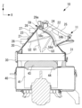
- FIG. 1 is a longitudinal cross-sectional view showing a blower unit according to an embodiment of the present disclosure.
- 2 is a sectional view taken along the line AA in FIG. 1.
- FIG. 3 is a sectional view taken along the line BB in FIG. 2.
- FIG. 3 is a sectional view showing a modification of FIG. 2.
- blower device blower unit
- the vertical direction will be referred to as the Z-axis direction
- one direction perpendicular to the Z-axis direction will be referred to as the X-axis direction
- the direction perpendicular to the Z-axis direction and the X-axis direction will be referred to as the Y-axis direction.
- the air blower according to the present embodiment is applied, for example, to a vehicle air conditioner installed in a space defined by an instrument panel of an automobile.
- the blower device will be referred to as a "blower unit.”
- a vehicle air conditioner is a temperature regulating device (HVAC unit) that controls the temperature of air outside the vehicle (hereinafter referred to as “outside air") or air inside the vehicle (hereinafter referred to as “inside air”) and blows it into the vehicle interior.
- HVAC unit includes an air conditioning unit (Air Conditioning Unit) and a blower unit 10 that supplies outside air or inside air to the HVAC unit. The illustration of the HVAC unit is omitted.
- the blower unit 10 includes a casing 11 that serves as an outer shell.
- the housing 11 has an air flow path formed therein through which outside air or inside air flows.
- the housing 11 sucks inside air or outside air from inside air suction port 23 or outside air suction port 24 formed at the upper end, and sucks inside air or outside air from fan suction port 44 formed at the lower end.
- the housing 11 includes an inclined part 20 provided at the upper part, a filter accommodating part 30 connected to the lower end of the inclined part 20 and accommodating a filter (capturing part) 31 inside, and a filter accommodating part 30.
- the fan accommodating part 40 is connected to the lower end of the fan accommodating part 40 and accommodates a fan 41 therein.
- the inclined part 20 includes a plate-shaped internal air suction part 21 extending diagonally downward from the center in the X-axis direction toward one side in the X-axis direction, and a plate-shaped inside air suction part 21 extending diagonally downward from the center in the X-axis direction toward the other side in the It has a plate-shaped outside air suction part 22 that extends.
- the inside air suction section 21 and the outside air suction section 22 are connected at their upper ends and at their inner ends.
- a inside air intake port 23 is formed in the inside air intake section 21 .
- the internal air intake port 23 connects the external space and internal space of the housing 11 .
- the inside air suction port 23 is connected to an inside air suction duct (not shown) whose upstream end communicates with the interior space of the vehicle. The inside air sucked from the inside air suction duct is sucked into the inside of the housing 11 via the inside air intake port 23.
- the inside air intake port 23 is provided with a lattice portion (attachment portion) 26.
- the grid portion 26 covers the inside air intake port 23 from the outside.
- the grid portion 26 includes a plate-shaped member extending in the X-axis direction along the inside air intake port 23 and a plate-shaped member extending in the Y-axis direction.
- the lattice portion 26 is fixed to the housing 11 (inside air intake portion 21).
- a first ultraviolet ray irradiation device (first ultraviolet irradiation unit) 27 and a second ultraviolet ray irradiation device (second ultraviolet ray irradiation unit) 28 are attached to the grid portion 26 .
- the first ultraviolet irradiation device 27 and the second ultraviolet irradiation device 28 are arranged at positions overlapping the inside air inlet 23 when the inside air inlet 23 is viewed from above.
- the first ultraviolet irradiation device 27 is provided above the second ultraviolet irradiation device 28.
- the first ultraviolet irradiation device 27 is provided above the center of the inclined portion 20 in the Z-axis direction.
- the second ultraviolet irradiation device 28 is provided below the center of the inclined portion 20 in the Z-axis direction.
- the first ultraviolet irradiation device 27 is provided closer to the center in the X-axis direction (the center of the inclined portion 20) than the second ultraviolet irradiation device 28 is.
- the first ultraviolet irradiation device 27 is provided on the other side of the center of the inside air intake section 21 in the X-axis direction (on the right side of the paper in FIG. 2).
- the second ultraviolet irradiation device 28 is provided on one side of the center of the inside air suction section 21 in the X-axis direction (on the left side of the paper in FIG. 2).
- the first ultraviolet irradiation device 27 and the second ultraviolet irradiation device 28 irradiate ultraviolet rays.
- the first ultraviolet irradiation device 27 and the second ultraviolet irradiation device 28 sterilize and inactivate viruses and microorganisms attached to particles or mist floating in the air flowing inside the housing by irradiating ultraviolet rays. Purify the air.
- the first ultraviolet irradiation device 27 and the second ultraviolet irradiation device 28 irradiate a filter 31, which will be described later, with ultraviolet rays (in detail, the second ultraviolet irradiation device 28 has a reflection plate (reflection part) 29c (The filter 31 is irradiated with ultraviolet light through the filter 31.) Therefore, the first ultraviolet irradiation device 27 and the second ultraviolet irradiation device 28 mainly sterilize and inactivate viruses and microorganisms that adhere to particles and mist captured by the filter 31.
- the first ultraviolet irradiation device 27 and the second ultraviolet irradiation device 28 are not limited as long as they are devices that irradiate ultraviolet rays.
- the first ultraviolet irradiation device 27 and the second ultraviolet irradiation device 28 are devices that have some degree of directivity in irradiating ultraviolet rays, such as devices in which an LED that irradiates ultraviolet rays is attached to a substrate. You can.
- the first ultraviolet ray irradiation device 27 irradiates ultraviolet rays toward the filter 31, as shown by arrow U1 in FIG. Specifically, the first ultraviolet irradiation device 27 irradiates ultraviolet rays toward a predetermined area A (see FIG. 3) of the filter 31.
- the predetermined region A is a region through which the main flow of air within the casing 11 passes.
- the predetermined area A includes an area that overlaps with the bellmouth-shaped fan suction port 44 when the filter 31 is viewed from above, as shown by the two-dot chain line in FIG.
- the second ultraviolet ray irradiation device 28 irradiates ultraviolet rays toward a reflecting plate 29c, which will be described later, as shown by arrow U2 in FIG.
- a part of the ultraviolet rays reflected by the reflection plate 29c is irradiated toward a predetermined area A of the filter 31, as shown by an arrow U3.
- the ultraviolet rays irradiated from the first ultraviolet irradiation device 27 and the second ultraviolet ray irradiation device 28 are shown by one arrow, but in reality, the ultraviolet rays irradiated from the first ultraviolet ray irradiation device 27 and the second ultraviolet ray irradiation device 28 are shown in each direction with the direction shown by the arrow as the center. It is irradiated with a spread of about 60 degrees. In the first ultraviolet irradiation device 27 and the second ultraviolet irradiation device 28, the amount of ultraviolet rays decreases as the distance from the center of ultraviolet irradiation (in the direction indicated by the arrow) increases; Not reduced.
- the distance L from the center of the inside air intake port 23 to the center of the filter 31 is approximately 100 mm.
- the diameter D (see FIG. 3) of the area above the bell mouth through which a large amount of wind passes is set to be 200 mm or more and 250 mm or less. Therefore, when the first ultraviolet ray irradiation device 27 irradiates ultraviolet light toward the center of the filter 31, the above-mentioned predetermined area A can be included in the range of 30 degrees from the center. Therefore, the predetermined region A where particles and the like are likely to be captured can be more effectively irradiated with ultraviolet rays.
- An outside air intake port 24 is formed in the outside air intake section 22 .
- the outside air intake port 24 connects the external space and internal space of the housing 11.
- An outside air intake duct 25 for sucking outside air is connected to the outside air intake port 24 .
- the outside air sucked in from the outside air intake duct 25 is sucked into the interior of the casing 11 via the outside air intake port 24.
- an intake damper 29 is provided inside the inclined portion 20.
- the intake damper 29 is provided on the lower surface of the connecting portion between the inside air intake section 21 and the outside air intake section 22.
- the intake damper 29 has a cylindrical rotating shaft portion 29a extending along the Y-axis direction, and a plate-shaped closing portion 29b having one end fixed to the rotating shaft portion 29a.
- the rotating shaft portion 29a is fixed to the lower surface of the connecting portion between the inside air suction portion 21 and the outside air suction portion 22 so as to be rotatable at a predetermined angle about a central axis extending along the Y-axis direction.
- the closing portion 29b is larger than the inside air suction port 23 and the outside air suction port 24, and is capable of closing the inside air suction port 23 and the outside air suction port 24.
- the closing portion 29b moves with the rotation of the rotating shaft portion 29a. Specifically, it moves between a position where the inside air intake port 23 is covered and closed from the inside and a position where the outside air intake port 24 is covered and closed from the inside. That is, the intake damper 29 can switch between a state in which the inside air intake port 23 is closed and a state in which the outside air intake port 24 is closed.
- a reflecting plate 29c is provided on one surface of the closing portion 29b (the surface facing the internal space of the housing 11 when the intake damper 29 closes the outside air inlet 24).
- the reflecting plate 29c is made of a material (for example, aluminum) that can reflect ultraviolet rays.
- the reflecting plate 29c is a flat member.
- the reflecting plate 29c is attached to one surface of the closing portion 29b so as to cover substantially the entire surface thereof.
- the reflecting plate 29c is provided so as to face the filter 31 when the intake damper 29 closes the outside air intake port 24.
- the filter accommodating portion 30 is a rectangular frame-shaped member when viewed from above.
- the filter accommodating part 30 has an upper end connected to the lower end of the inclined part 20, and a lower end connected to the upper end of the fan accommodating part 40.
- a filter 31 is accommodated within the filter accommodating portion 30 over substantially the entire area in the X-axis direction and the Y-axis direction.
- the filter 31 is provided so as to cover substantially the entire cross section of the flow path.
- the filter 31 is provided within the filter housing section 30.
- the filter 31 is provided downstream of the first ultraviolet irradiation device 27 .
- the filter 31 captures particles or mist floating in the air when the air (inside air or outside air) flowing through the housing 11 passes through.
- the filter 31 may be made of a nonwoven fabric, or may be made of a material having photocatalytic properties.
- viruses and the like are inactivated by irradiating the filter 31 with ultraviolet rays, so an inexpensive filter such as a non-woven fabric can be used instead of using an expensive filter such as a photocatalyst filter.
- it can purify the air sufficiently. Therefore, when an inexpensive filter such as a nonwoven fabric is employed, it is possible to obtain a sufficient air purifying effect and reduce costs.
- the filter 31 has a plurality of pleats. That is, in the filter 31, mountain-like portions and valley-like portions extending in the X-axis direction are arranged alternately along the Y-axis direction.
- the first ultraviolet irradiation device 27 irradiates ultraviolet rays in the X-axis direction. In this way, by irradiating ultraviolet rays from the same direction as the extending direction of the mountain-like portions, it is possible to make the ultraviolet rays less likely to be blocked by the mountain-like portions. Therefore, even the valley-shaped portions can be suitably irradiated with ultraviolet rays.
- the fan accommodating portion 40 is a circular member when viewed from above, and accommodates a fan 41 therein, as shown in FIGS. 1 and 2.
- the fan accommodating portion 40 has a fan suction port 44 formed in the bottom portion.
- the fan suction port 44 communicates the internal space of the housing 11 with the external space.
- the fan 41 has a plurality of blades 42 arranged at regular intervals along the edge of the fan suction port 44.
- the fan accommodating portion 40 is provided with a plate-shaped reinforcing member 43 so as to straddle the fan suction port 44 .
- the two reinforcing members 43 are arranged to form a cross in plan view, and prevent the filter from being sucked in.
- the blower unit 10 also includes a control section (not shown). By controlling the intake damper 29, the control unit can switch between a state where the intake damper 29 closes the inside air intake port 23 and a state where the intake damper 29 closes the outside air intake port 24. It also controls starting and stopping of the first ultraviolet irradiation device 27 and the second ultraviolet irradiation device 28 .
- the control unit has an inside air mode and an outside air mode.
- the inside air mode is a mode in which the air (inside air) inside the vehicle is sucked in, the temperature of the sucked air is adjusted, and then the air is discharged into the cabin.
- the outside air mode is a mode in which air outside the vehicle (outside air) is sucked in, the temperature of the sucked air is adjusted, and then the air is discharged into the passenger compartment.
- the control unit controls the first ultraviolet irradiation device 27 and the second ultraviolet irradiation device 28 so as to stop irradiation of ultraviolet rays when the intake damper 29 closes the inside air intake port 23 in the outside air mode. Further, in the inside air mode, the control unit controls the first ultraviolet irradiation device 27 and the second ultraviolet irradiation device 28 so as to irradiate the ultraviolet rays while the intake damper 29 closes the outside air inlet 24.
- the controller includes, for example, a CPU (Central Processing Unit), a main memory, a secondary storage (memory), and the like. Furthermore, the control unit may include a communication unit for transmitting and receiving information to and from other devices.
- the main storage device is made up of a writable memory such as a cache memory or a RAM (Random Access Memory), and is used as a work area for reading an execution program of the CPU, writing processing data by the execution program, and the like.
- Secondary storage is a non-transitory computer readable storage medium.
- the secondary storage device is, for example, a magnetic disk, a magneto-optical disk, a CD-ROM, a DVD-ROM, a semiconductor memory, or the like.
- a series of processes for realizing various functions is stored in a secondary storage device in the form of a program, for example, and the CPU reads this program into the main storage device and executes information processing and arithmetic processing. By doing so, various functions are realized.
- the program may be pre-installed in a secondary storage device, stored in a computer-readable storage medium, or distributed via wired or wireless communication means. may be applied.
- Computer-readable storage media include magnetic disks, magneto-optical disks, CD-ROMs, DVD-ROMs, semiconductor memories, and the like.
- FIG. 2 illustrates a state in which the intake damper 29 closes the outside air intake port 24 and opens the inside air intake port 23 (that is, the state in the inside air mode).
- the control section controls the intake damper 29 so that the closing section 29b closes the outside air intake port 24.
- the inside air intake port 23 is in an open state, so that inside air (air inside the vehicle interior) is sucked into the housing 11 through the inside air intake port 23.
- the internal air sucked into the housing 11 flows within the housing 11 from above to below.
- it passes through a filter 31.
- the main flow of inside air passes through a predetermined region A of the filter 31 because it flows through a route with little pressure loss.
- the filter 31 In the predetermined region A of the filter 31, a large amount of internal air passes through, so more particles and the like are captured than in other regions.
- the inside air that has passed through the filter 31 and been purified is discharged from the fan suction port 44 to the outside of the housing 11, and is supplied to the HVAC unit via a duct (not shown) or the like, and the temperature is adjusted by the HVAC unit.
- the temperature-adjusted internal air is blown into the vehicle interior.
- the control unit irradiates ultraviolet rays from the first ultraviolet irradiation device 27 and the second ultraviolet irradiation device 28 .
- the first ultraviolet irradiation device 27 irradiates ultraviolet rays toward a predetermined area A of the filter 31 (see arrow U1 in FIG. 2). This inactivates viruses and the like attached to particles and the like captured by the filter 31 (particularly in the predetermined area A).
- the second ultraviolet ray irradiation device 28 irradiates ultraviolet rays toward the reflecting plate 29c, as shown by arrow U2 in FIG. A part of the ultraviolet rays reflected by the reflection plate 29c is irradiated toward a predetermined area A of the filter 31, as shown by an arrow U3. This inactivates viruses and the like attached to particles and the like captured by the filter 31 (particularly in the predetermined area A).
- control section controls the intake damper 29 so that the closing section 29b closes the inside air intake port 23.
- the outside air intake port 24 is in an open state, so outside air (air outside the vehicle) is sucked into the housing 11 through the outside air intake port 24.
- the flow of outside air sucked into the housing 11 is the same as the flow of inside air inside the housing 11, so a detailed explanation will be omitted.
- the ultraviolet irradiation section is provided so as to overlap the inside air inlet 23 when the inside air inlet 23 is viewed from above. Therefore, in the outside air mode in which the intake damper 29 closes the inside air intake port 23, even if the first ultraviolet ray irradiation device 27 and the second ultraviolet ray irradiation device 28 emit ultraviolet rays, the closed portion 29b of the intake damper 29 is obstructed and does not reach the filter 31. In addition, in outside air mode, the inside of the car can be ventilated, so irradiation with ultraviolet rays is not necessary. Therefore, in the outside air mode, the control unit does not irradiate ultraviolet light from the first ultraviolet irradiation device 27 and the second ultraviolet irradiation device 28 .
- the first ultraviolet irradiation device 27 and the second ultraviolet irradiation device 28 irradiate the filter 31 with ultraviolet rays. This makes it possible to inactivate microorganisms, viruses, etc. attached to the floating matter captured by the filter 31.
- the first ultraviolet irradiation device 27 and the second ultraviolet irradiation device 28 are provided in the covering part, which is a stationary object fixed to the housing 11.
- the first ultraviolet irradiation device 27 and the second ultraviolet irradiation device 28 are provided on a moving body such as a rotating body, the first ultraviolet irradiation device 27 and the second ultraviolet ray irradiation device 28 are connected to other devices (e.g. , power supply, etc.), the wiring can be simplified. Therefore, the installation work of the first ultraviolet irradiation device 27 and the second ultraviolet irradiation device 28 can be simplified.
- the control unit controls the first ultraviolet irradiation device 27 and the second ultraviolet irradiation device 28 so as to irradiate ultraviolet rays while the intake damper 29 opens the inside air inlet 23.
- the first ultraviolet irradiation device 27 and the second ultraviolet irradiation device 28 are provided so as to overlap with the inside air inlet 23 when the inside air inlet 23 is viewed from above. Therefore, when the intake damper 29 closes the inside air intake port 23, even if ultraviolet rays are irradiated, the ultraviolet rays are blocked by the intake damper 29 and do not reach the filter 31.
- the control unit stops irradiation of ultraviolet rays while the intake damper 29 closes the inside air intake port 23, so that unnecessary irradiation of ultraviolet rays can be suppressed. Therefore, energy can be saved and energy efficiency can be improved.
- a first ultraviolet irradiation device 27 is provided in a grid portion 26 provided so as to cover the inside air intake port 23 .
- the ultraviolet rays emitted from the first ultraviolet irradiation device 27 are strongly irradiated to the region of the filter 31 on the inside air intake port 23 side, which is close to the first ultraviolet irradiation device 27.
- a region of the filter 31 on the outside air intake port 24 side, which is relatively far away, is weakly irradiated.
- the reflection plate 29c is provided so as to face the filter 31 in a state where the intake damper 29 closes the outside air intake port 24.
- the reflection plate 29c can reflect the ultraviolet rays irradiated from the second ultraviolet irradiation device 28 to the filter 31.
- the ultraviolet rays reflected by the reflection plate 29c are strongly irradiated to a region of the filter 31 on the outside air intake port 24 side, which is close to the reflection plate 29c.
- a region of the filter 31 on the inside air intake port 23 side, which is relatively far from the reflection plate 29c, is weakly irradiated.
- the region of the filter 31 on the inside air intake port 23 side is strongly irradiated with ultraviolet rays from the first ultraviolet ray irradiation device 27 and the second ultraviolet ray irradiation device 28, the first ultraviolet rays reflected by the reflection plate 29c
- the ultraviolet rays from the irradiation device 27 and the second ultraviolet irradiation device 28 are weakly irradiated.
- the region of the filter 31 on the outside air intake port 24 side is weakly irradiated with ultraviolet rays from the first ultraviolet irradiation device 27 and the second ultraviolet ray irradiation device 28, the first ultraviolet ray irradiation reflected by the reflector plate 29c
- the ultraviolet rays from the device 27 and the second ultraviolet irradiation device 28 are intensely irradiated. Therefore, variations in the intensity of the ultraviolet rays irradiated onto the filter 31 can be reduced.
- the first ultraviolet irradiation device 27 located above irradiates the filter 31 with ultraviolet rays.
- the first ultraviolet irradiation device 27 is placed above (that is, placed away from the filter 31). Therefore, the ultraviolet rays irradiated from the first ultraviolet irradiation device 27 tend to spread to reach the filter 31. Therefore, for example, compared to a structure in which the filter 31 is irradiated with ultraviolet rays by the second ultraviolet irradiation device 28, a wider range of the filter 31 can be irradiated with ultraviolet rays.
- the closing portion 59b of the intake damper 59 has a concave central region. Specifically, the closing portion 59b is formed with a recessed portion 59d having a spherical recess on one surface (the surface facing the internal space of the housing 11 when the intake damper 29 closes the outside air inlet 24). Note that the region other than the central region of the closing portion 59b (other than the recessed portion 59d) is shaped like a flat plate. By doing this, when closing the inside air intake port 23 and the outside air intake port 24, surface contact can be made with the edges of each opening, so the inside air intake port 23 and the outside air intake port 24 can be effectively closed. be able to.
- the reflector 59c is curved to correspond to the shape of the recess 59d. Specifically, one surface (the surface facing the internal space of the housing 11) is curved in a spherical concave manner.
- the reflective plate 59c is attached to the recess 59d so as to cover the entire area of the recess 59d.
- the reflecting plate 59c is recessed so that when reflecting the ultraviolet rays emitted from the second ultraviolet irradiation device 28, the reflected ultraviolet rays are concentrated on the filter 31.
- the reflecting plate 59c is recessed so that the reflected ultraviolet rays are concentrated on the filter 31.
- more ultraviolet rays can be irradiated onto the filter 31, so that viruses and the like attached to the floating matter captured by the filter 31 can be more preferably inactivated. Therefore, the air blown into the vehicle interior can be purified.
- the present disclosure is not limited to the above-described embodiments, and can be modified as appropriate without departing from the gist thereof.
- two ultraviolet irradiation devices the first ultraviolet irradiation device 27 and the second ultraviolet irradiation device 28, are provided, but the present disclosure is not limited thereto. Only either the first ultraviolet irradiation device 27 or the second ultraviolet irradiation device 28 may be provided. Further, a plurality of first ultraviolet irradiation devices 27 may be provided, and a plurality of second ultraviolet irradiation devices 28 may be provided.
- the first ultraviolet irradiation device 27 and the second ultraviolet irradiation device 28 are automatically started and stopped by the control device.
- the first ultraviolet ray irradiation device 27 and the second ultraviolet ray irradiation device 28 may be started and stopped by a limit switch.
- the blower device described in the embodiment described above can be understood, for example, as follows.
- the blower device according to the first aspect of the present disclosure supplies outside air or inside air to the temperature adjustment device that adjusts the temperature of outside air, which is air outside the vehicle, or inside air, which is air inside the vehicle interior, and blows it into the vehicle interior.
- a blower device comprising: a casing (11) forming an outer shell; an inside air intake port (23) provided in the casing for sucking inside air into the inside of the casing; an outside air intake port (24) that is provided and that sucks outside air into the interior of the casing; an intake damper (29) that selectively closes the inside air intake port or the outside air intake port; a trapping section (31) that captures floating matter floating in the air sucked into the housing; a first ultraviolet irradiation section (27) that irradiates the trapping section with ultraviolet rays; a mounting part (26) fixed to the inside air inlet, provided so as to cover the inside air inlet, and to which the first ultraviolet ray irradiation part is attached, the first ultraviolet ray irradiation part when the inside air inlet is viewed from above. In some cases, it is provided so as to overlap with the inside air intake port.
- the first ultraviolet irradiation unit irradiates the capture unit with ultraviolet rays. Thereby, it is possible to inactivate microorganisms, viruses, etc. attached to the floating matter captured by the capturing section.
- the first ultraviolet irradiation section is provided in the covering section, which is a stationary object fixed to the casing.
- the first ultraviolet irradiation section is provided on a moving body such as a rotating body, when the first ultraviolet ray irradiation section is connected to another device (for example, a power source, etc.) by wiring, wiring, etc.
- the handling can be simplified. Therefore, the work of attaching the first ultraviolet irradiation section can be simplified.
- irradiation of ultraviolet rays is stopped in a state in which the intake damper closes the inside air intake port, and the intake damper closes the outside air intake port.
- a control unit that controls the first ultraviolet irradiation unit so as to irradiate the ultraviolet rays when the first ultraviolet ray irradiation unit is closed.
- the control section controls the first ultraviolet ray irradiation section so as to irradiate the ultraviolet rays while the intake damper opens the inside air inlet. This makes it possible to inactivate viruses and the like adhering to floating matter captured by the capture unit when circulating indoor air that is likely to be contaminated. Therefore, the air blown into the vehicle interior can be purified.
- the first ultraviolet irradiation section is provided so as to overlap the inside air inlet when the inside air inlet is viewed from above. Therefore, in a state where the intake damper closes the inside air intake port, even if ultraviolet rays are irradiated, the ultraviolet rays are blocked by the intake damper and do not reach the trapping portion.
- the control unit stops irradiation of ultraviolet rays while the intake damper closes the inside air intake port, so that unnecessary irradiation of ultraviolet rays can be suppressed. Therefore, energy can be saved and energy efficiency can be improved.
- the blower device includes a reflecting part (29c) that reflects ultraviolet rays, and a second ultraviolet irradiation part that irradiates ultraviolet rays to the reflecting part. (28), wherein the reflecting portion is provided on a surface of the intake damper that faces the inside of the casing when the intake damper closes the outside air intake port, and the reflection portion It is provided so as to face the trapping part when the outside air intake port is closed.
- the first ultraviolet irradiation section is provided in the mounting section provided so as to cover the inside air intake port.
- the ultraviolet rays irradiated from the first ultraviolet ray irradiation section are strongly irradiated to a region of the trapping section on the inside air intake port side that is close to the first ultraviolet irradiation section.
- a region of the trapping section on the outside air intake port side, which is relatively far away, is weakly irradiated.
- the reflecting section is provided so as to face the capturing section in a state where the intake damper closes the outside air intake port.
- the reflecting section can reflect the ultraviolet rays irradiated from the second ultraviolet irradiating section to the capturing section.
- the ultraviolet rays reflected by the reflection part are strongly irradiated to a region of the trapping part on the outside air intake port side, which is close to the reflection part.
- a region of the trapping section on the inside air inlet side which is relatively far from the reflecting section, is weakly irradiated.
- the region of the trapping section on the inside air inlet side is strongly irradiated with ultraviolet rays from the first ultraviolet irradiating section, but is weakly irradiated with ultraviolet rays from the second ultraviolet irradiating section that is reflected by the reflecting section. .
- the region of the trapping section on the outside air inlet side is weakly irradiated with ultraviolet rays from the first ultraviolet irradiating section, but is strongly irradiated with ultraviolet rays from the second ultraviolet irradiating section that is reflected by the reflecting section. Therefore, variations in the intensity of the ultraviolet rays irradiated onto the trapping section can be reduced.
- the reflecting section collects reflected ultraviolet rays in the trapping section in a state where the intake damper closes the outside air inlet. It's recessed like that.
- the reflecting section is recessed so that the reflected ultraviolet rays are concentrated on the capturing section.
- more ultraviolet rays can be irradiated onto the trapping section, so that viruses and the like attached to the floating matter captured by the trapping section can be more suitably inactivated. Therefore, the air blown into the vehicle interior can be purified.
Landscapes
- Engineering & Computer Science (AREA)
- Mechanical Engineering (AREA)
- Disinfection, Sterilisation Or Deodorisation Of Air (AREA)
- Air-Conditioning For Vehicles (AREA)
Abstract
Description
本開示の一態様に係る送風装置は、車両外部の空気である外気又は車室内の空気である内気の温度を調整し前記車室内に吹出す温度調整装置に対して、外気又は内気を供給する送風装置であって、外殻を為す筐体と、前記筐体に設けられ、前記筐体の内部に内気を吸入する内気吸入口と、前記筐体に設けられ、前記筐体の内部に外気を吸入する外気吸入口と、前記内気吸入口又は前記外気吸入口を選択的に閉鎖するインテークダンパと、前記筐体の内部に設けられ、前記筐体の内部に吸入した空気中を浮遊する浮遊物を捕捉する捕捉部と、前記捕捉部に対して紫外線を照射する第1紫外線照射部と、前記筐体に固定され、前記内気吸入口を覆うように設けられ、前記第1紫外線照射部が取り付けられる取付部と、を備え、前記第1紫外線照射部は、前記内気吸入口を平面視した際に、前記内気吸入口と重複するように設けられている。
第1紫外線照射装置27は、第2紫外線照射装置28よりも上方に設けられている。第1紫外線照射装置27は、傾斜部20におけるZ軸方向の中心よりも上方に設けられている。第2紫外線照射装置28は、傾斜部20におけるZ軸方向の中心よりも下方に設けられている。
また、第1紫外線照射装置27は、第2紫外線照射装置28よりもX軸方向の中心(傾斜部20の中心)側に設けられている。第1紫外線照射装置27は、内気吸入部21におけるX軸方向の中心よりも他側(図2における紙面右側)に設けられている。第2紫外線照射装置28は、内気吸入部21におけるX軸方向の中心よりも一側(図2における紙面左側)に設けられている。
また、第2紫外線照射装置28は、図2の矢印U2に示すように、紫外線を後述の反射板29cに向かって照射する。反射板29cによって反射した紫外線の一部は、矢印U3で示すように、フィルタ31の所定の領域Aに向かって照射される。
本実施形態では、内気吸入口23の中心からフィルタ31の中心までの距離Lが略100mmとされている。また、ベルマウス上の風が多く通過する範囲の直径D(図3参照)は、200mm以上であって250mm以下とされている。このため、第1紫外線照射装置27からフィルタ31の中心に向かって紫外線を照射した場合、中心から30度の範囲に上述の所定の領域Aを含めることができる。このため、粒子等が捕捉され易い所定の領域Aに対して、より効果的に紫外線を照射することができる。
インテークダンパ29は、Y軸方向に沿って延在する円柱状の回転軸部29aと、一端が回転軸部29aに固定されている板状の閉鎖部29bと、を有する。回転軸部29aは、内気吸入部21と外気吸入部22との接続部分の下面に、Y軸方向に沿って延在する中心軸線を中心として所定の角度回動可能に固定されている。閉鎖部29bは、内気吸入口23及び外気吸入口24よりも大きく、内気吸入口23及び外気吸入口24を閉鎖可能とされている。
図3に示すように、フィルタ収容部30の内部には、X軸方向及びY軸方向の略全域に亘ってフィルタ31が収容されている。フィルタ31は、流路断面の略全域を覆うように設けられている。
本実施形態では、図2に示すように、第1紫外線照射装置27は、X軸方向に紫外線を照射している。このように、山状の部分の延在方向と同じ方向から紫外線を照射することで、山状の部分に紫外線を遮られ難くすることができる。したがって、谷状の部分にも紫外線を好適に照射することができる。
ファン41は、図3に示すように、ファン吸い込み口44の縁に沿って並んで等間隔に配置された複数の羽根42を有する。ファン41が駆動することで、複数の羽根42が回転し、内気吸入口23又は外気吸入口24を介して筐体11内に内気又は外気を吸入する。
ファン収容部40は、ファン吸い込み口44と跨ぐように、板状の補強部材43が設けられている。2枚の補強部材43は、平面視で十字となるように配置されており、フィルタが吸い込まれることを防止している。
制御部は、外気モードにおいてインテークダンパ29が内気吸入口23を閉鎖している状態において紫外線の照射を停止するように第1紫外線照射装置27及び第2紫外線照射装置28を制御する。また、制御部は、内気モードにおいて、インテークダンパ29が外気吸入口24を閉鎖している状態において紫外線を照射するように第1紫外線照射装置27及び第2紫外線照射装置28を制御する。
主記憶装置は、例えば、キャッシュメモリ、RAM(Random Access Memory)等の書き込み可能なメモリで構成され、CPUの実行プログラムの読み出し、実行プログラムによる処理データの書き込み等を行う作業領域として利用される。
二次記憶装置は、非一時的なコンピュータ読み取り可能な記録媒体(non-transitory computer readable storage medium)である。二次記憶装置は、例えば、磁気ディスク、光磁気ディスク、CD-ROM、DVD-ROM、半導体メモリなどである。
各種機能を実現するための一連の処理は、一例として、プログラムの形式で二次記憶装置に記憶されており、このプログラムをCPUが主記憶装置に読み出して、情報の加工・演算処理を実行することにより、各種機能が実現される。なお、プログラムは、二次記憶装置に予めインストールしておく形態や、コンピュータ読み取り可能な記憶媒体に記憶された状態で提供される形態、有線又は無線による通信手段を介して配信される形態等が適用されてもよい。コンピュータ読み取り可能な記憶媒体とは、磁気ディスク、光磁気ディスク、CD-ROM、DVD-ROM、半導体メモリ等である。
まず、内気モードにおける空気の流れ等について説明する。
筐体11内に吸入された内気は、筐体11内を上方から下方へ流通する。その際に、フィルタ31を通過する。この時、内気の主流は、圧力損失が少ないルートを流通するため、フィルタ31のうち、所定の領域Aを通過する。フィルタ31を通過する際に、内気中を浮遊する粒子等がフィルタ31に捕捉される。フィルタ31の所定の領域Aは、多くの内気が通過することから他の領域よりも多くの粒子等が捕捉される。
フィルタ31を通過して清浄化された内気はファン吸い込み口44から筐体11の外部へ排出され、ダクト(図示省略)等を介してHVACユニットに供給され、HVACユニットで温度が調整される。温度が調整された内気は、車室内に吹出される。
また、第2紫外線照射装置28は、図2の矢印U2に示すように、紫外線を反射板29cに向かって照射する。反射板29cで反射した紫外線の一部は、矢印U3で示すように、フィルタ31の所定の領域Aに向かって照射される。これにより、フィルタ31(特に所定の領域A)に捕捉された粒子等に付着したウイルス等を不活化する。
まず、外気モードにおける空気の流れ等について説明する。
筐体11内に吸入された外気の流れは、筐体11内の内気の流れと同じであるので、詳細な説明は省略する。
本実施形態では、第1紫外線照射装置27及び第2紫外線照射装置28がフィルタ31に対して紫外線を照射している。これにより、フィルタ31で捕捉した浮遊物に付着している微生物やウイルス等を不活化することができる。
本実施形態では、制御部が、インテークダンパ29が内気吸入口23を開放している状態において紫外線を照射するように第1紫外線照射装置27及び第2紫外線照射装置28を制御している。これにより、空気が汚染され易い内気を循環させる場合において、フィルタ31で捕捉した浮遊物に付着しているウイルス等を不活化することができる。したがって、車室内に吹出される空気を清浄化することができる。
一方で、本実施形態では、反射板29cが、インテークダンパ29が外気吸入口24を閉鎖している状態において、フィルタ31と対向するように設けられている。これにより、反射板29cは、第2紫外線照射装置28から照射された紫外線をフィルタ31へ反射することができる。反射板29cが反射した紫外線は、フィルタ31のうち、反射板29cからの距離が近い外気吸入口24側の領域には強く照射される。一方で、フィルタ31のうち、反射板29cからの距離が比較的遠い内気吸入口23側の領域には弱く照射される。
このように、フィルタ31のうち内気吸入口23側の領域には、第1紫外線照射装置27及び第2紫外線照射装置28からの紫外線が強く照射されるものの、反射板29cが反射する第1紫外線照射装置27及び第2紫外線照射装置28からの紫外線は弱く照射される。一方で、フィルタ31のうち外気吸入口24側の領域には、第1紫外線照射装置27及び第2紫外線照射装置28からの紫外線が弱く照射されるものの、反射板29cが反射する第1紫外線照射装置27及び第2紫外線照射装置28からの紫外線は強く照射される。したがって、フィルタ31に照射される紫外線の強さのばらつきを低減することができる。
次に、上記実施形態の変形例について図4を用いて説明する。
本変形例では、インテークダンパの閉鎖部の形状及び反射板の形状が上記実施形態と異なっている。その他の点は上記実施形態と同様であるので、同様の構成について同一の符号を付してその詳細な説明は省略する。
なお、閉鎖部59bの中心領域以外(凹部59d以外)の領域は、平板状とされている。このようにすることで、内気吸入口23及び外気吸入口24を閉鎖する際に、各開口の縁と面接触することができるので、効果的に内気吸入口23及び外気吸入口24を閉鎖することができる。
本変形例では、反射板59cが、反射する紫外線がフィルタ31に集約するように凹んでいる。これにより、より多くの紫外線をフィルタ31に照射することができるので、より好適に、フィルタ31で捕捉した浮遊物に付着しているウイルス等を不活化することができる。したがって、車室内に吹出される空気を清浄化することができる。
例えば、上記実施形態では、第1紫外線照射装置27及び第2紫外線照射装置28の2つを設ける例について説明したが、本開示はこれに限定されない。第1紫外線照射装置27または第2紫外線照射装置28のどちらか一方のみを設けてもよい。また、第1紫外線照射装置27を複数設けてもよく、また、第2紫外線照射装置28を複数設けてもよい。
本開示の第1態様に係る送風装置は、車両外部の空気である外気又は車室内の空気である内気の温度を調整し前記車室内に吹出す温度調整装置に対して、外気又は内気を供給する送風装置(10)であって、外殻を為す筐体(11)と、前記筐体に設けられ、前記筐体の内部に内気を吸入する内気吸入口(23)と、前記筐体に設けられ、前記筐体の内部に外気を吸入する外気吸入口(24)と、前記内気吸入口又は前記外気吸入口を選択的に閉鎖するインテークダンパ(29)と、前記筐体の内部に設けられ、前記筐体の内部に吸入した空気中を浮遊する浮遊物を捕捉する捕捉部(31)と、前記捕捉部に対して紫外線を照射する第1紫外線照射部(27)と、前記筐体に固定され、前記内気吸入口を覆うように設けられ、前記第1紫外線照射部が取り付けられる取付部(26)と、を備え、前記第1紫外線照射部は、前記内気吸入口を平面視した際に、前記内気吸入口と重複するように設けられている。
上記構成では、制御部が、インテークダンパが内気吸入口を開放している状態において紫外線を照射するように第1紫外線照射部を制御している。これにより、空気が汚染され易い内気を循環させる場合において、捕捉部で捕捉した浮遊物に付着しているウイルス等を不活化することができる。したがって、車室内に吹出される空気を清浄化することができる。
一方で、上記構成では、反射部が、インテークダンパが外気吸入口を閉鎖している状態において、捕捉部と対向するように設けられている。これにより、反射部は、第2紫外線照射部から照射された紫外線を捕捉部へ反射することができる。反射部が反射した紫外線は、捕捉部のうち、反射部からの距離が近い外気吸入口側の領域には強く照射される。一方で、捕捉部のうち、反射部からの距離が比較的遠い内気吸入口側の領域には弱く照射される。
このように、捕捉部のうち内気吸入口側の領域には、第1紫外線照射部からの紫外線が強く照射されるものの、反射部が反射する第2紫外線照射部からの紫外線は弱く照射される。一方で、捕捉部のうち外気吸入口側の領域には、第1紫外線照射部からの紫外線が弱く照射されるものの、反射部が反射する第2紫外線照射部からの紫外線は強く照射される。したがって、捕捉部に照射される紫外線の強さのばらつきを低減することができる。
11 :筐体
20 :傾斜部
21 :内気吸入部
22 :外気吸入部
23 :内気吸入口
24 :外気吸入口
25 :外気吸入ダクト
26 :格子部(取付部)
27 :第1紫外線照射装置(第1紫外線照射部)
28 :第2紫外線照射装置(第2紫外線照射部)
29 :インテークダンパ
29a :回転軸部
29b :閉鎖部
29c :反射板(反射部)
30 :フィルタ収容部
31 :フィルタ(捕捉部)
40 :ファン収容部
41 :ファン
42 :羽根
43 :補強部材
44 :ファン吸い込み口
59 :インテークダンパ
59b :閉鎖部
59c :反射板
59d :凹部
Claims (4)
- 車両外部の空気である外気又は車室内の空気である内気の温度を調整し前記車室内に吹出す温度調整装置に対して、外気又は内気を供給する送風装置であって、
外殻を為す筐体と、
前記筐体に設けられ、前記筐体の内部に内気を吸入する内気吸入口と、
前記筐体に設けられ、前記筐体の内部に外気を吸入する外気吸入口と、
前記内気吸入口又は前記外気吸入口を選択的に閉鎖するインテークダンパと、
前記筐体の内部に設けられ、前記筐体の内部に吸入した空気中を浮遊する浮遊物を捕捉する捕捉部と、
前記捕捉部に対して紫外線を照射する第1紫外線照射部と、
前記筐体に固定され、前記内気吸入口を覆うように設けられ、前記第1紫外線照射部が取り付けられる取付部と、を備え、
前記第1紫外線照射部は、前記内気吸入口を平面視した際に、前記内気吸入口と重複するように設けられている送風装置。 - 前記インテークダンパが前記内気吸入口を閉鎖している状態において紫外線の照射を停止し、前記インテークダンパが前記外気吸入口を閉鎖している状態において紫外線を照射するように前記第1紫外線照射部を制御する制御部を備える請求項1に記載の送風装置。
- 紫外線を反射する反射部と、
前記反射部に対して紫外線を照射する第2紫外線照射部と、を備え、
前記反射部は、前記インテークダンパが前記外気吸入口を閉鎖する際に前記筐体の内部に面する前記インテークダンパの面に設けられていて、前記インテークダンパが前記外気吸入口を閉鎖している状態において、前記捕捉部と対向するように設けられている請求項1または請求項2に記載の送風装置。 - 前記反射部は、前記インテークダンパが前記外気吸入口を閉鎖している状態において、反射する紫外線が前記捕捉部に集約するように凹んでいる請求項3に記載の送風装置。
Priority Applications (2)
| Application Number | Priority Date | Filing Date | Title |
|---|---|---|---|
| CN202380057040.7A CN119630546A (zh) | 2022-08-05 | 2023-08-03 | 送风装置 |
| DE112023002550.9T DE112023002550T5 (de) | 2022-08-05 | 2023-08-03 | Gebläsevorrichtung |
Applications Claiming Priority (2)
| Application Number | Priority Date | Filing Date | Title |
|---|---|---|---|
| JP2022125549A JP2024022168A (ja) | 2022-08-05 | 2022-08-05 | 送風装置 |
| JP2022-125549 | 2022-08-05 |
Publications (1)
| Publication Number | Publication Date |
|---|---|
| WO2024029601A1 true WO2024029601A1 (ja) | 2024-02-08 |
Family
ID=89849489
Family Applications (1)
| Application Number | Title | Priority Date | Filing Date |
|---|---|---|---|
| PCT/JP2023/028464 Ceased WO2024029601A1 (ja) | 2022-08-05 | 2023-08-03 | 送風装置 |
Country Status (4)
| Country | Link |
|---|---|
| JP (1) | JP2024022168A (ja) |
| CN (1) | CN119630546A (ja) |
| DE (1) | DE112023002550T5 (ja) |
| WO (1) | WO2024029601A1 (ja) |
Citations (4)
| Publication number | Priority date | Publication date | Assignee | Title |
|---|---|---|---|---|
| JP2004001616A (ja) * | 2002-05-31 | 2004-01-08 | Mitsubishi Heavy Ind Ltd | 車両用空調装置 |
| JP2007097797A (ja) * | 2005-10-04 | 2007-04-19 | Calsonic Kansei Corp | 光触媒フィルター |
| KR20220043479A (ko) * | 2020-09-29 | 2022-04-05 | 한온시스템 주식회사 | 살균장치가 구비된 차량용 공조장치 |
| JP2022084410A (ja) * | 2020-11-26 | 2022-06-07 | 本田技研工業株式会社 | 車両用空調装置 |
-
2022
- 2022-08-05 JP JP2022125549A patent/JP2024022168A/ja active Pending
-
2023
- 2023-08-03 WO PCT/JP2023/028464 patent/WO2024029601A1/ja not_active Ceased
- 2023-08-03 CN CN202380057040.7A patent/CN119630546A/zh active Pending
- 2023-08-03 DE DE112023002550.9T patent/DE112023002550T5/de active Pending
Patent Citations (4)
| Publication number | Priority date | Publication date | Assignee | Title |
|---|---|---|---|---|
| JP2004001616A (ja) * | 2002-05-31 | 2004-01-08 | Mitsubishi Heavy Ind Ltd | 車両用空調装置 |
| JP2007097797A (ja) * | 2005-10-04 | 2007-04-19 | Calsonic Kansei Corp | 光触媒フィルター |
| KR20220043479A (ko) * | 2020-09-29 | 2022-04-05 | 한온시스템 주식회사 | 살균장치가 구비된 차량용 공조장치 |
| JP2022084410A (ja) * | 2020-11-26 | 2022-06-07 | 本田技研工業株式会社 | 車両用空調装置 |
Also Published As
| Publication number | Publication date |
|---|---|
| JP2024022168A (ja) | 2024-02-16 |
| DE112023002550T5 (de) | 2025-05-15 |
| CN119630546A (zh) | 2025-03-14 |
Similar Documents
| Publication | Publication Date | Title |
|---|---|---|
| JP6250155B2 (ja) | 光触媒装置及びこれを備える車両用空調装置 | |
| KR101935813B1 (ko) | 광촉매 장치 및 이를 포함하는 차량용 공조장치 | |
| KR101973536B1 (ko) | 광촉매 장치 | |
| KR20040023602A (ko) | 습도 조정용 엘리먼트, 습도 조정 장치, 및 공기 조화장치의 가습 유닛 | |
| US12115293B2 (en) | Photocatalytic oxidation centrifugal fan | |
| JP2024022168A (ja) | 送風装置 | |
| JP2004352235A (ja) | 騒音減衰器付き車室の送風装置 | |
| JP2022160293A (ja) | 紫外線照射装置、および、その紫外線照射装置を備えた空気調和機用室内機 | |
| WO2021124925A1 (ja) | 車両用空調装置 | |
| KR20160036853A (ko) | 차량용 공조장치 | |
| WO2023074587A1 (ja) | 空気調和機 | |
| JP3028806B2 (ja) | 空気清浄装置 | |
| JP3230454B2 (ja) | 空気清浄装置 | |
| JP4461786B2 (ja) | 空気清浄システム | |
| JP7356042B2 (ja) | 空気調和機 | |
| JP2023066160A (ja) | 空気調和機 | |
| KR20160036857A (ko) | 차량용 공조장치 | |
| KR20160035828A (ko) | 광촉매 장치 | |
| KR20200049960A (ko) | 광촉매 기능을 구비하는 전기자동차용 공조장치 | |
| JP2022127074A (ja) | 車両用空調システム | |
| JP2004291864A (ja) | 車両用空調装置のブロアユニット | |
| JP2022084410A (ja) | 車両用空調装置 | |
| JP7332932B2 (ja) | 空気調和機 | |
| KR20180076681A (ko) | 광촉매 장치 및 이를 포함하는 차량용 공조장치 | |
| JP2022051137A (ja) | 循環送風機器 |
Legal Events
| Date | Code | Title | Description |
|---|---|---|---|
| 121 | Ep: the epo has been informed by wipo that ep was designated in this application |
Ref document number: 23850154 Country of ref document: EP Kind code of ref document: A1 |
|
| WWE | Wipo information: entry into national phase |
Ref document number: 202380057040.7 Country of ref document: CN |
|
| WWE | Wipo information: entry into national phase |
Ref document number: 2501000649 Country of ref document: TH |
|
| WWE | Wipo information: entry into national phase |
Ref document number: 112023002550 Country of ref document: DE |
|
| WWP | Wipo information: published in national office |
Ref document number: 202380057040.7 Country of ref document: CN |
|
| WWP | Wipo information: published in national office |
Ref document number: 112023002550 Country of ref document: DE |
|
| 122 | Ep: pct application non-entry in european phase |
Ref document number: 23850154 Country of ref document: EP Kind code of ref document: A1 |