WO2024029235A1 - 半導体装置 - Google Patents
半導体装置 Download PDFInfo
- Publication number
- WO2024029235A1 WO2024029235A1 PCT/JP2023/023839 JP2023023839W WO2024029235A1 WO 2024029235 A1 WO2024029235 A1 WO 2024029235A1 JP 2023023839 W JP2023023839 W JP 2023023839W WO 2024029235 A1 WO2024029235 A1 WO 2024029235A1
- Authority
- WO
- WIPO (PCT)
- Prior art keywords
- lead
- resin
- semiconductor device
- thickness direction
- back surface
- Prior art date
- Legal status (The legal status is an assumption and is not a legal conclusion. Google has not performed a legal analysis and makes no representation as to the accuracy of the status listed.)
- Ceased
Links
Images




Classifications
-
- H—ELECTRICITY
- H10—SEMICONDUCTOR DEVICES; ELECTRIC SOLID-STATE DEVICES NOT OTHERWISE PROVIDED FOR
- H10W—GENERIC PACKAGES, INTERCONNECTIONS, CONNECTORS OR OTHER CONSTRUCTIONAL DETAILS OF DEVICES COVERED BY CLASS H10
- H10W72/00—Interconnections or connectors in packages
-
- H—ELECTRICITY
- H10—SEMICONDUCTOR DEVICES; ELECTRIC SOLID-STATE DEVICES NOT OTHERWISE PROVIDED FOR
- H10W—GENERIC PACKAGES, INTERCONNECTIONS, CONNECTORS OR OTHER CONSTRUCTIONAL DETAILS OF DEVICES COVERED BY CLASS H10
- H10W74/00—Encapsulations, e.g. protective coatings
-
- H—ELECTRICITY
- H10—SEMICONDUCTOR DEVICES; ELECTRIC SOLID-STATE DEVICES NOT OTHERWISE PROVIDED FOR
- H10W—GENERIC PACKAGES, INTERCONNECTIONS, CONNECTORS OR OTHER CONSTRUCTIONAL DETAILS OF DEVICES COVERED BY CLASS H10
- H10W74/00—Encapsulations, e.g. protective coatings
- H10W74/40—Encapsulations, e.g. protective coatings characterised by their materials
Definitions
- the present disclosure relates to a semiconductor device.
- Patent Document 1 describes a first lead, a second lead, and a third lead including a die pad portion having a main surface and a back surface, a semiconductor element mounted on the main surface, and a die pad part that is in contact with the main surface and which supports the semiconductor element.
- An example of a semiconductor device including a sealing resin for covering the semiconductor device is disclosed. The back surface of the die pad portion is exposed from the sealing resin.
- the back surface of the die pad section is used to radiate heat from the semiconductor element to the outside. For this reason, it is preferable that the back surface of the die pad portion be maintained in an appropriate state.
- An object of the present disclosure is to provide a semiconductor device that is improved over the conventional semiconductor device. Particularly, in view of the above-mentioned circumstances, one object of the present disclosure is to provide a semiconductor device that can bring the back surface of a die pad portion into a more appropriate state.
- a semiconductor device provided by one aspect of the present disclosure includes a semiconductor element, a first lead main surface facing one side in the thickness direction and on which the semiconductor element is mounted, and a first lead main surface facing the other side in the thickness direction.
- a first lead including a die pad portion having a back surface of the first lead, a first terminal portion, a first resin surface facing the one side in the thickness direction, and a second resin surface facing the other side in the thickness direction.
- a sealing resin having a surface and covering the semiconductor element and a part of the die pad portion.
- the back surface of the first lead is exposed from the second resin surface.
- the first terminal portion includes a portion located on the one side in the thickness direction with respect to the first lead main surface and used for mounting. At least one of the first lead back surface and the second resin surface has a surface roughness greater than that of the first resin surface.
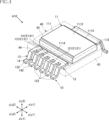
- FIG. 1 is a perspective view showing a semiconductor device according to a first embodiment of the present disclosure.
- FIG. 2 is a perspective view showing a semiconductor device according to the first embodiment of the present disclosure.
- FIG. 3 is a perspective view showing a semiconductor device according to the first embodiment of the present disclosure.
- FIG. 4 is a perspective view of essential parts of a semiconductor device according to a first embodiment of the present disclosure.
- FIG. 5 is a perspective view of a main part of a semiconductor device according to a first embodiment of the present disclosure.
- FIG. 6 is a plan view showing a semiconductor device according to the first embodiment of the present disclosure.
- FIG. 7 is a bottom view showing the semiconductor device according to the first embodiment of the present disclosure.
- FIG. 1 is a perspective view showing a semiconductor device according to a first embodiment of the present disclosure.
- FIG. 2 is a perspective view showing a semiconductor device according to the first embodiment of the present disclosure.
- FIG. 3 is a perspective view showing a semiconductor device according to the first embodiment
- FIG. 8 is a front view showing the semiconductor device according to the first embodiment of the present disclosure.
- FIG. 9 is a side view showing the semiconductor device according to the first embodiment of the present disclosure.
- FIG. 10 is a plan view of main parts showing a semiconductor device according to a first embodiment of the present disclosure.
- FIG. 11 is a bottom view of essential parts showing the semiconductor device according to the first embodiment of the present disclosure.
- FIG. 12 is a sectional view taken along line XII-XII in FIG. 11.
- FIG. 13 is a cross-sectional view taken along line XIII-XIII in FIG. 11.
- FIG. 14 is a sectional view taken along line XIV-XIV in FIG. 11.
- FIG. 15 is a sectional view taken along line XV-XV in FIG. 11.
- FIG. 11 is a sectional view taken along line XV-XV in FIG. 11.
- FIG. 16 is an enlarged cross-sectional view of a main part of the semiconductor device according to the first embodiment of the present disclosure.
- FIG. 17 is an enlarged cross-sectional view of a main part of the semiconductor device according to the first embodiment of the present disclosure.
- FIG. 18 is a cross-sectional view showing how the semiconductor device according to the first embodiment of the present disclosure is used.
- FIG. 19 is a plan view showing one state in the manufacturing process of the semiconductor device according to the first embodiment of the present disclosure.
- FIG. 20 is an enlarged sectional view of a main part showing one state in the manufacturing process of the semiconductor device according to the first embodiment of the present disclosure.
- FIG. 21 is an enlarged cross-sectional view of a main part showing a manufacturing process of a semiconductor device according to a first embodiment of the present disclosure.
- FIG. 22 is a plan view showing a first modification of the semiconductor device according to the first embodiment of the present disclosure.
- FIG. 23 is an enlarged cross-sectional view of main parts showing a first modification of the semiconductor device according to the first embodiment of the present disclosure.
- FIG. 24 is a plan view showing a second modification of the semiconductor device according to the first embodiment of the present disclosure.
- FIG. 25 is a plan view showing a third modification of the semiconductor device according to the first embodiment of the present disclosure.
- FIG. 26 is a plan view showing a fourth modification of the semiconductor device according to the first embodiment of the present disclosure.
- FIG. 27 is an enlarged cross-sectional view of a main part showing a manufacturing process of a fourth modification example of the semiconductor device according to the first embodiment of the present disclosure.
- FIG. 28 is an enlarged sectional view of a main part of a semiconductor device according to a second embodiment of the present disclosure.
- FIG. 29 is an enlarged cross-sectional view of main parts showing a first modification of the semiconductor device according
- a thing A is formed on a thing B and "a thing A is formed on a thing B” mean “a thing A is formed on a thing B” unless otherwise specified.
- "something A is placed on something B” and “something A is placed on something B” mean "something A is placed on something B” unless otherwise specified.
- a certain surface A faces (one side or the other side of) the direction B is not limited to the case where the angle of the surface A with respect to the direction B is 90 degrees; Including cases where it is tilted to the opposite direction.
- First embodiment: 1 to 21 show a semiconductor device according to a first embodiment of the present disclosure.
- the semiconductor device A10 of this embodiment includes a conductive member 10, a semiconductor element 20, connection members 31, 32, 33, and a sealing resin 40.
- the thickness direction of the present disclosure is defined as the thickness direction z.
- One side in the thickness direction z is referred to as the z1 side, and the other side opposite to the one side in the thickness direction z is referred to as the z2 side.
- one direction perpendicular to the thickness direction z is defined as a first direction x.
- One side in the first direction x is referred to as the x1 side, and the other side opposite to the x1 side is referred to as the x2 side.
- a direction perpendicular to the thickness direction z and the first direction x is defined as a second direction y.
- One side in the second direction y is referred to as the y1 side, and the other side opposite to the y1 side is referred to as the y2 side.
- the conductive member 10 is a member that constitutes a conductive path to the semiconductor element 20.
- the conductive member 10 of this embodiment includes a first lead 11, a second lead 12, a third lead 13, and a fourth lead 14.
- the materials of the first lead 11, second lead 12, third lead 13, and fourth lead 14 are not limited at all, and include, for example, copper (Cu) or a copper alloy. Further, the first lead 11, the second lead 12, the third lead 13, and the fourth lead 14 may be plated with silver (Ag), nickel (Ni), bell (Sn), etc. at appropriate locations. .
- the first lead 11 has a die pad portion 111 and a first terminal portion 112.
- the die pad portion 111 has a first lead main surface 1111 and a first lead back surface 1112.
- the first lead main surface 1111 is a surface facing the z1 side in the thickness direction z.
- the first lead back surface 1112 is a surface facing the z2 side in the thickness direction z.
- a semiconductor element 20 is mounted on the first lead main surface 1111.
- the die pad section 111 of this embodiment further includes a first lead side surface 1113, a first intermediate surface 1114, and a second intermediate surface 1115.
- the first lead side surface 1113 is located between the first lead main surface 1111 and the first lead back surface 1112 in the thickness direction z, and is a surface facing the x1 side in the first direction x.
- the first intermediate surface 1114 is located between the first lead main surface 1111 and the first lead back surface 1112 in the thickness direction z, and is located on the z2 side (the same side as the first lead back surface 1112) in the thickness direction z. This is the side that faces.
- the first intermediate surface 1114 is located on the x2 side in the first direction x with respect to the first lead back surface 1112.
- the second intermediate surface 1115 is located between the first lead main surface 1111 and the first lead back surface 1112 in the thickness direction z, and is located on the z2 side (the same side as the first lead back surface 1112) in the thickness direction z. This is the side that faces.
- the second intermediate surface 1115 is located on the x1 side in the first direction x with respect to the first lead back surface 1112.
- the shape of the die pad portion 111 is not limited at all.
- the die pad portion 111 has a rectangular shape when viewed in the thickness direction z.
- the shapes of the first lead main surface 1111 and the first lead back surface 1112 are not limited in any way, and in the illustrated example, they are rectangular when viewed in the thickness direction z.
- the first terminal section 112 has a first section 1121, two second sections 1122, and two third sections 1123.
- the first part 1121 is connected to the die pad part 111, extends from the die pad part 111 in the x1 side of the first direction x, and is parallel to the xy plane in the illustrated example.
- the die pad portion 111 is larger in the thickness direction z than the first portion 1121.
- the first terminal section 112 of this embodiment has only one first section 1121.
- the shape of the first portion 1121 is not limited at all, and in the illustrated example, it is rectangular when viewed in the thickness direction z.
- the first portion 1121 is separated from the first lead back surface 1112 in the thickness direction z, and is in contact with the first lead main surface 1111 in the illustrated example. One side of the first portion 1121 is flush with the first lead main surface 1111.
- the two second parts 1122 are located on the z1 side in the thickness direction z with respect to the first part 1121.
- the two second parts 1122 are used when surface mounting the semiconductor device A10 on a circuit board or the like.
- the two third parts 1123 are interposed between the first part 1121 and the two second parts 1122.
- the third portion 1123 extends from the first portion 1121 toward the z1 side in the thickness direction z.
- the third portion 1123 is inclined with respect to the thickness direction z so as to extend outward from the first portion 1121 in the second direction y.
- the shape of the third portion 1123 is not limited at all, and in the illustrated example, it has a rectangular shape when viewed in the first direction x.
- the two second parts 1122 extend outward in the first direction x from the two third parts 1123. Moreover, the two second parts 1122 are parallel to the second direction y. The two second parts 1122 do not protrude from the two third parts 1123 toward the x1 side in the first direction x. In the illustrated example, the two second parts 1122 and the two third parts 1123 are at the same (or substantially the same) position in the first direction x.
- the second lead 12 is located away from the first lead 11 (die pad portion 111) on the x2 side in the first direction x.
- the second lead 12 has a pad portion 121 and a plurality of second terminal portions 122.
- the pad portion 121 has a second lead main surface 1211 and a second lead back surface 1212.
- the second lead main surface 1211 is a surface facing the z1 side in the thickness direction z.
- the second lead back surface 1212 is a surface facing the z2 side in the thickness direction z.
- a connecting member 31 is connected to the second lead main surface 1211.
- the shape of the pad portion 121 is not limited at all, and in the illustrated example, it is a long rectangular shape whose longitudinal direction is the second direction y.
- the pad portion 121 is smaller than the die pad portion 111 when viewed in the thickness direction z. Further, the pad portion 121 has a smaller size in the thickness direction z than the die pad portion 111, and is the same (or approximately the same) as the first terminal portion 112.
- the second lead main surface 1211 is located at the same (or substantially the same) position in the thickness direction z as the first lead main surface 1111 of the die pad portion 111 .
- the plurality of second terminal portions 122 are arranged in line in the second direction y.
- the second terminal section 122 has a fourth section 1221, a fifth section 1222, and a sixth section 1223.
- the fourth portion 1221 is connected to the pad portion 121, extends from the pad portion 121 toward the x2 side in the first direction x, and is parallel to the xy plane in the illustrated example.
- the shape of the fourth portion 1221 is not limited in any way, and in the illustrated example, it has a rectangular shape when viewed in the thickness direction z.
- the fifth portion 1222 is located on the z1 side in the thickness direction z with respect to the fourth portion 1221.
- the fifth portion 1222 is used when surface mounting the semiconductor device A10 on a circuit board or the like.
- the fifth portion 1222 has a shape extending along the first direction x.
- the sixth part 1223 is interposed between the fourth part 1221 and the fifth part 1222.
- the sixth portion 1223 extends from the fourth portion 1221 toward the z1 side in the thickness direction z.
- the sixth portion 1223 is inclined with respect to the thickness direction z (yz plane).
- the shape of the sixth portion 1223 is not limited in any way, and in the illustrated example, it has a rectangular shape when viewed in the first direction x.
- the third lead 13 is located away from the first lead 11 (die pad portion 111) on the x2 side in the first direction x. Further, the third lead 13 is lined up with the second lead 12 in the second direction y, and is located on the y2 side of the second lead 12 in the second direction y. The third lead 13 has a pad portion 131 and a third terminal portion 132.
- the pad portion 131 has a third lead main surface 1311 and a third lead back surface 1312.
- the third lead main surface 1311 is a surface facing the z1 side in the thickness direction z.
- the third lead back surface 1312 is a surface facing the z2 side in the thickness direction z.
- a connecting member 32 is connected to the third lead main surface 1311.
- the shape of the pad portion 131 is not limited in any way, and in the illustrated example, it has a rectangular shape when viewed in the thickness direction z. Further, the pad portion 131 is smaller than the pad portion 121 when viewed in the thickness direction z. Furthermore, the pad portion 131 has a smaller size in the thickness direction z than the die pad portion 111, and is the same (or approximately the same) as the pad portion 121.
- the third lead main surface 1311 is located at the same (or substantially the same) position in the thickness direction z as the first lead main surface 1111 of the die pad portion 111 .
- the third terminal section 132 has a seventh section 1321, an eighth section 1322, and a ninth section 1323.
- the seventh portion 1321 is connected to the pad portion 131, extends from the pad portion 131 toward the x2 side in the first direction x, and is parallel to the xy plane in the illustrated example.
- the shape of the seventh portion 1321 is not limited at all, and in the illustrated example, it has a rectangular shape when viewed in the thickness direction z.
- the eighth portion 1322 is located on the z1 side in the thickness direction z with respect to the seventh portion 1321.
- the eighth portion 1322 is used when surface mounting the semiconductor device A10 on a circuit board or the like.
- the eighth portion 1322 has a shape extending along the first direction x.
- the ninth part 1323 is interposed between the seventh part 1321 and the eighth part 1322.
- the ninth portion 1323 extends from the seventh portion 1321 toward the z1 side in the thickness direction z.
- the ninth portion 1323 is inclined with respect to the thickness direction z (yz plane).
- the shape of the ninth portion 1323 is not limited in any way, and in the illustrated example, it has a rectangular shape when viewed in the first direction x.
- the fourth lead 14 is located away from the first lead 11 (die pad portion 111) on the x2 side in the first direction x. Further, the fourth lead 14 is located between the second lead 12 and the third lead 13 in the second direction y. The fourth lead 14 has a pad portion 141 and a fourth terminal portion 142.
- the pad portion 141 has a fourth lead main surface 1411 and a fourth lead back surface 1412.
- the fourth lead main surface 1411 is a surface facing the z1 side in the thickness direction z.
- the fourth lead back surface 1412 is a surface facing the z2 side in the thickness direction z.
- a connecting member 33 is connected to the fourth lead main surface 1411.
- the shape of the pad portion 141 is not limited in any way, and in the illustrated example, it has a rectangular shape when viewed in the thickness direction z. Further, when viewed in the thickness direction z, the pad portion 141 is smaller than the pad portion 121 and approximately the same size as the pad portion 131.
- the pad portion 141 has a smaller size in the thickness direction z than the die pad portion 111, and is the same (or approximately the same) as the pad portion 121 and the pad portion 131.
- the position of the fourth lead main surface 1411 in the thickness direction z is the same (or substantially the same) as the first lead main surface 1111 of the die pad portion 111 .
- the fourth terminal section 142 has a tenth section 1421, an eleventh section 1422, and a twelfth section 1423.
- the tenth portion 1421 is connected to the pad portion 141, extends from the pad portion 141 toward the x2 side in the first direction x, and is parallel to the xy plane in the illustrated example.
- the shape of the tenth portion 1421 is not limited in any way, and in the illustrated example, it is rectangular when viewed in the thickness direction z.
- the eleventh part 1422 is located on the z1 side in the thickness direction z with respect to the tenth part 1421.
- the eleventh portion 1422 is used when surface mounting the semiconductor device A10 on a circuit board or the like.
- the eleventh portion 1422 has a shape extending along the first direction x.
- the twelfth part 1423 is interposed between the tenth part 1421 and the eleventh part 1422.
- the twelfth portion 1423 extends from the tenth portion 1421 toward the z1 side in the thickness direction z.
- the twelfth portion 1423 is inclined with respect to the thickness direction z (yz plane).
- the shape of the twelfth portion 1423 is not limited at all, and in the illustrated example, it has a rectangular shape when viewed in the first direction x.
- the semiconductor element 20 is mounted on the first lead main surface 1111 of the die pad section 111, as shown in FIG. 5 and FIGS. 11 to 15.
- the semiconductor element 20 is an n-channel type MOSFET (Metal-Oxide-Semiconductor Field-Effect Transistor) with a vertical structure.
- the semiconductor element 20 is not limited to a MOSFET.
- the semiconductor element 20 may be another transistor such as an IGBT (Insulated Gate Bipolar Transistor).
- the semiconductor element 20 may be a diode.
- the semiconductor element 20 has a semiconductor layer 205, a first electrode 201, a second electrode 202, and a third electrode 203.
- the semiconductor layer 205 includes a compound semiconductor substrate.
- the main material of the compound semiconductor substrate is silicon carbide (SiC).
- silicon (Si) may be used as the main material of the compound semiconductor substrate.
- the first electrode 201 is provided in a portion of the semiconductor layer 205 on the side (z1 side) toward which the first lead main surface 1111 of the die pad portion 111 of the first lead 11 faces in the thickness direction z.
- the first electrode 201 corresponds to the source electrode of the semiconductor element 20.
- the second electrode 202 is provided in a portion of the semiconductor layer 205 on the opposite side to the first electrode 201 in the thickness direction z.
- the second electrode 202 faces the first lead main surface 1111 of the die pad portion 111 of the first lead 11 .
- the second electrode 202 corresponds to the drain electrode of the semiconductor element 20.
- the second electrode 202 is bonded to the first lead main surface 1111 via the bonding layer 29.
- the bonding layer 29 is, for example, solder, silver (Ag) paste, fired silver, or the like.
- the third electrode 203 is provided in a portion of the semiconductor layer 205 on the same side as the first electrode 201 in the thickness direction z, and is located away from the first electrode 201 .
- the third electrode 203 corresponds to the gate electrode of the semiconductor element 20.
- the area of the third electrode 203 is smaller than the area of the first electrode 201 when viewed in the thickness direction z.
- connection members 31, 32, 33 The connecting member 31 is joined to the first electrode 201 of the semiconductor element 20 and the second lead main surface 1211 of the pad portion 121 of the second lead 12 .
- the material of the connecting member 31 is not limited at all, and includes metals such as aluminum (Al), copper (Cu), and gold (Au).
- the number of connection members 31 is not limited at all, and a plurality of connection members 31 may be provided.
- the connecting member 31 includes aluminum (Al) and is a flat strip-shaped member.
- the connecting member 32 is connected to the third electrode 203 of the semiconductor element 20 and the third lead main surface 1311 of the pad portion 131 of the third lead 13.
- the connecting member 32 is a linear member that contains gold (Au) and is thinner than the connecting member 31 .
- the connecting member 33 is connected to the first electrode 201 of the semiconductor element 20 and the fourth lead main surface 1411 of the pad portion 141 of the fourth lead 14.
- the connecting member 33 is a linear member that contains gold (Au) and is thinner than the connecting member 31 .
- the first terminal portion 112 of the first lead 11 is a drain terminal
- the second terminal portion 122 of the second lead 12 is a source terminal
- the third terminal portion 132 of the third lead 13 is a drain terminal.
- the fourth terminal portion 142 of the fourth lead 14 is a source sense terminal.
- Sealing resin 40 As shown in FIGS. 1 to 15, the sealing resin 40 seals the semiconductor element 20, the connecting members 31, 32, 33, and each of the first lead 11, second lead 12, third lead 13, and fourth lead 14. partially covered.
- the sealing resin 40 has electrical insulation properties.
- the sealing resin 40 is made of a material containing, for example, a black epoxy resin.
- the sealing resin 40 has a first resin surface 41 , a second resin surface 42 , a third resin surface 43 , a fourth resin surface 44 , a fifth resin surface 45 , and a sixth resin surface 46 .
- the first resin surface 41 faces the same side (z1 side) as the first lead main surface 1111 of the die pad portion 111 of the first lead 11 in the thickness direction z.
- the second resin surface 42 faces the opposite side (z2 side) from the first resin surface 41 in the thickness direction z.
- a first lead back surface 1112 of the die pad portion 111 of the first lead 11 is exposed from the second resin surface 42 .
- the second resin surface 42 and the first lead back surface 1112 are flush with each other.
- the first lead back surface 1112 is separated from the third resin surface 43 in the first direction x.
- the third resin surface 43 faces the x1 side in the first direction x.
- the first portion 1121 of the first terminal portion 112 of the first lead 11 penetrates the third resin surface 43 .
- only one first portion 1121 penetrates the third resin surface 43.
- the first portion 1121 is separated from the second resin surface 42 in the thickness direction z.
- the fourth resin surface 44 faces the opposite side (x2 side) from the third resin surface 43 in the first direction x.
- the second terminal portion 122 of the plurality of second terminal portions 122 of the second lead 12, the seventh portion 1321 of the third terminal portion 132 of the third lead 13, and the fourth terminal portion of the fourth lead 14 are The tenth portion 1421 of 142 penetrates the fourth resin surface 44 .
- the fifth resin surface 45 faces the y1 side in the second direction y.
- the sixth resin surface 46 faces the y2 side in the second direction y.
- the second direction y ends of the two second parts 1122 of the second terminal part 122 of the first lead 11 are connected to the fifth resin surface 45 of the sealing resin 40 and the 6 is located at approximately the same position as the resin surface 46.
- the two second parts 1122 do not protrude from the fifth resin surface 45 and the sixth resin surface 46 in the second direction y.
- the sealing resin 40 has grooves 49.
- the groove 49 is recessed from the second resin surface 42 toward the z1 side in the thickness direction z, and extends along the second direction y.
- the groove 49 reaches the fifth resin surface 45 and the sixth resin surface 46.
- the groove 49 is located between the first lead back surface 1112 and the fourth resin surface 44.
- the sealing resin 40 has two recesses 47.
- the two recesses 47 are recessed from the first resin surface 41 toward the z2 side in the thickness direction z.
- the illustrated recess 47 is constituted by a through hole extending from the first resin surface 41 to the first lead main surface 1111. Therefore, a portion of the first lead main surface 1111 is exposed from the recess 47.
- the semiconductor device A10 has grinding marks CM formed across the first lead back surface 1112 and the second resin surface 42.
- the appearance (specific shape) of the grinding marks CM is not limited at all.
- the grinding mark CM consists of a plurality of circular lines. Note that in FIG. 10, the grinding marks CM are omitted.
- the state shown in these figures is a state in which the sealing resin 40 has been formed through a resin molding process using a mold, for example.
- the illustrated sealing resin 40 has an extending portion 409 .
- the extending portion 409 covers a portion of the first lead back surface 1112 of the die pad portion 111, and constitutes a portion of the second resin surface 42 in the illustrated state.
- Such an extending portion 409 may be caused by, for example, the degree to which the first lead back surface 1112 of the die pad portion 111 is not pressed against the mold toward the z2 side in the thickness direction z during a resin molding process using a mold. This may occur due to the fact that the flatness of the back surface 1112 of the first lead is not sufficient.
- the first resin surface 41 and the second resin surface 42 are both surfaces formed by a mold, have almost the same surface roughness, and have no significant difference.
- FIG. 21 shows the process of removing the extending portion 409.
- the first lead back surface 1112 and the second resin surface 42 of the die pad portion 111 are ground using a grinding tool CT such as a rotating grindstone tool.
- a grinding tool CT such as a rotating grindstone tool.
- the extending portion 409 is removed, and grinding marks CM shown in FIGS. 6 and 16 are formed on the first lead back surface 1112 and the second resin surface 42.
- the grinding marks CM shown in FIG. 6 are an example of a case where the grinding tool CT is a rotating grinding tool or the like, and the specific pattern shape of the grinding marks CM is not limited at all. As shown in FIG.
- the hardness of the grinding tool as the grinding tool CT or the hardness of the abrasive grains contained in the polishing slurry , etc. may be harder than both the first lead back surface 1112 and the second resin surface 42.
- Grinding marks CM are formed on at least one of the first lead back surface 1112 and the second resin surface 42 that have been processed using the grinding tool CT.
- the area where the grinding marks CM are formed has a larger surface roughness than the first resin surface 41 which has not been processed using the grinding tool CT.
- FIG. 18 shows the usage state of the semiconductor device A10.
- the semiconductor device A10 is surface mounted on the circuit board 92. That is, the second part 1122 of the first terminal part 112, the fifth part 1222 of the second terminal part 122, the eighth part 1322 of the third terminal part 132, and the eleventh part 1422 of the fourth terminal part 142 are, for example, solder 921. It is electrically connected to the wiring pattern (not shown) of the circuit board 92 by means of the circuit board 92 . Further, a heat sink 91 is disposed opposite to the first lead back surface 1112 of the die pad portion 111 . In the illustrated example, a sheet material 919 is disposed between the first lead back surface 1112 and the heat sink 91. The sheet material 919 is, for example, an insulating sheet.
- the first lead back surface 1112 is exposed from the second resin surface 42.
- the heat sink 91 can be placed opposite the first lead back surface 1112.
- at least one of the first lead back surface 1112 and the second resin surface 42 has a larger surface roughness than the first resin surface 41.
- Such a configuration is an aspect obtained as a result of removing the extension portion 409 shown in FIG. 19 by the method illustrated in FIG. 21 or the like. Therefore, it is possible to prevent the first lead back surface 1112 from being covered by a part of the sealing resin 40 and to arrange the entire surface of the first lead back surface 1112 to face the heat sink 91, for example. Therefore, the back surface 1112 of the first lead can be brought into a more appropriate state.
- both the first lead back surface 1112 and the second resin surface 42 have greater surface roughness than the first resin surface 41.
- Such a configuration is obtained as a result of sufficiently grinding both the die pad portion 111 and the sealing resin 40 using the grinding tool CT in the method illustrated in FIG. 21 or the like. Therefore, it is preferable to bring the back surface 1112 of the first lead into a more appropriate state.
- the second portion 1122 is located on one side of the first portion 1121 in the z direction. Thereby, it is possible to surface-mount the semiconductor device A10 onto the circuit board 92 or the like using the second portion 1122. Further, the first lead back surface 1112 is separated from the third resin surface 43 in the x direction. Further, the first portion 1121 is separated from the second resin surface 42 in the z direction. Therefore, a portion of the sealing resin 40 exists between the first lead back surface 1112 and the first portion 1121. Thereby, the first lead 11 can be held more firmly by the sealing resin 40.
- the first terminal section 112 has a third section 1123. Thereby, the second portion 1122 can be supported more reliably.
- the third portion 1123 is parallel to the thickness direction z. Therefore, the x dimension of the semiconductor device A10 in the first direction can be reduced.
- the first terminal section 112 has two second sections 1122. Thereby, the mounting strength of the semiconductor device A10 can be increased.
- the two second parts 1122 extend outward in the first direction x from the third part 1123. Thereby, the mounting strength of the semiconductor device A10 can be further increased.
- the size of the first portion 1121 in the second direction y is smaller than the size of the die pad portion 111 in the second direction y. Thereby, the holding force of the first lead 11 by the sealing resin 40 can be further increased.
- the second portion 1122 does not protrude from the third portion 1123 in the first direction x. Thereby, the x dimension of the semiconductor device A10 in the first direction can be reduced.
- a groove 49 is formed in the sealing resin 40.
- the surface of the sealing resin 40 from the first lead back surface 1112 to the second lead 12 (fourth part 1221), third lead 13 (seventh part 1321), and fourth lead 14 (tenth part 1421) (hereinafter referred to as creepage distance) can be extended.
- First embodiment First modification 22 and 23 show a first modification of the semiconductor device A10.
- grinding marks CM are formed on the second resin surface 42, and no clear grinding marks CM are formed on the first lead back surface 1112.
- the surface roughness of the second resin surface 42 is greater than that of the first resin surface 41, and the surface roughness of the first lead back surface 1112 is the same as that of the first resin surface 41. It is about the same level.
- the second resin surface 42 is located closer to the z1 side in the thickness direction z than the first lead back surface 1112.
- Conditions for forming the first lead back surface 1112 and the second resin surface 42 of this modification include, for example, the hardness of the grinding tool as the grinding tool CT, the hardness of the abrasive grains contained in the polishing slurry, etc.
- the hardness may be softer than that of the back surface 1112 and harder than both of the second resin surface 42.
- This modification also allows the first lead back surface 1112 to be in a more appropriate state. Moreover, as understood from this modification, since the grinding marks CM are clearly formed only on the second resin surface 42, the surface roughness of the second resin surface 42 is greater than that of the first resin surface 41. , the surface roughness of the first lead back surface 1112 may be equivalent to the surface roughness of the first resin surface 41. Further, the second resin surface 42 is located on the z1 side in the thickness direction z than the first lead back surface 1112, and the first lead back surface 1112 is located on the z2 side in the thickness direction z than the second resin surface 42. Thereby, in the usage state described with reference to FIG. 18, the first lead back surface 1112 and the heat sink 91 can be pressed with a higher pressing force. Thereby, heat radiation from the first lead 11 can be further promoted.
- FIG. 24 shows a second modification of the semiconductor device A10.
- clear grinding marks CM are formed on the first lead back surface 1112, and no clear grinding marks CM are formed on the second resin surface 42.
- Such variations may occur depending on the configuration of the specific method selected as the method for removing the extension portion 409.
- This modification also allows the first lead back surface 1112 to be in a more appropriate state. Further, as understood from this modification, in the present disclosure, the surface roughness of at least one of the first lead back surface 1112 and the second resin surface 42 is greater than the surface roughness of the first resin surface 41.
- FIG. 25 shows a third modification of the semiconductor device A10.
- the grinding marks CM are composed of a plurality of straight lines. Such grinding marks CM may occur, for example, when the above-mentioned grinding tool CT is reciprocated linearly.
- This modification also allows the first lead back surface 1112 to be in a more appropriate state. Moreover, as understood from this modification, the specific shape (pattern) of the grinding marks CM is not limited at all.
- FIG. 26 shows a fourth modification of the semiconductor device A10.
- the sealing resin 40 includes a resin base material 401 and a plurality of fillers 402.
- the resin base material 401 is a continuous body made of a resin material, and includes, for example, black epoxy resin.
- a plurality of fillers 402 are mixed into the resin base material 401 in order to make desired properties of the sealing resin 40.
- the plurality of fillers 402 are made of silica (silicon dioxide), for example.
- the plurality of fillers 402 include a spherical filler 402 that is entirely buried in the resin base material 401 and a filler 402 that is exposed from the second resin surface 42 and forms a part of the second resin surface 42 .
- the filler 402 exposed from the second resin surface 42 has a spherical shape with a part removed, and forms a part of the second resin surface 42 (grinding marks CM).
- FIG. 27 shows the manufacturing process of the semiconductor device A14.
- the sealing resin 40 has the extending portion 409. Furthermore, in this state, almost all of the plurality of fillers 402 are buried in the resin base material 401 and maintain a spherical shape.
- the sealing resin 40 is ground by the grinding tool CT. At this time, a portion of the filler 402 existing near the second resin surface 42 is ground by the grinding tool CT, resulting in the state shown in FIG. 26.
- This modification also allows the first lead back surface 1112 to be in a more appropriate state. Moreover, as understood from this modification, the specific configuration of the sealing resin 40 is not limited at all.
- FIG. 28 shows a semiconductor device according to a second embodiment of the present disclosure.
- the die pad portion 111 includes a metal base material 1110 and a plating layer 1119.
- the metal base material 1110 is a portion that constitutes the majority of the die pad portion 111.
- the metal base material 1110 includes, for example, copper (Cu) or a copper alloy.
- Plating layer 1119 covers the surface of metal base material 1110.
- the plating layer 1119 contains, for example, silver (Ag), nickel (Ni), Suzu (Sn), or the like.
- the die pad portion 111 has the metal base material 1110 and does not have the plating layer 1119 yet.
- grinding marks CM of the same extent are formed on the metal base material 1110 and the second resin surface 42.
- the metal base material 1110 is subjected to an etching process. Through this treatment, the surface of the metal base material 1110 is positioned on the z1 side in the thickness direction z with respect to the second resin surface 42. Furthermore, the grinding marks CM existing on the surface of the metal base material 1110 are slightly flattened by etching, thereby becoming grinding marks CM2 having a surface roughness smaller than that of the grinding marks CM.
- a plating process is performed on the etched metal base material 1110 to form a plating layer 1119.
- grinding marks CM2 may remain on the interface 1118 between the metal base material 1110 and the plating layer 1119.
- the back surface 1112 of the first lead formed by the plating layer 1119 has a shape in which grinding marks CM2 remain or a substantially flat shape. Further, in the illustrated example, the first lead back surface 1112 constituted by the plating layer 1119 is located on the z1 side in the thickness direction z relative to the second resin surface 42.
- the first lead back surface 1112 can be brought into a more appropriate state. Further, in the case of the present embodiment, a configuration can be realized in which the first lead back surface 1112 is located on the z1 side in the thickness direction z rather than the second resin surface 42.
- FIG. 29 shows a first modification of the semiconductor device A20.
- the first lead back surface 1112 formed by the plating layer 1119 is located closer to the z2 side in the thickness direction z than the second resin surface 42.
- Such a configuration can be realized, for example, when the plating thickness in the plating process described in the semiconductor device A20 is thick.
- This modification also allows the first lead back surface 1112 to be in a more appropriate state. Further, according to this modification, it is possible to press the first lead back surface 1112 and the heat sink 91 with a higher pressing force while appropriately removing an oxide film or the like that may remain on the metal base material 1110.
- the semiconductor device according to the present disclosure is not limited to the embodiments described above.
- the specific configuration of each part of the semiconductor device according to the present disclosure can be changed in design in various ways.
- the present disclosure includes the embodiments described in the appendix below.
- a semiconductor element including a first lead main surface facing one side in the thickness direction and having the semiconductor element mounted thereon and a first lead back surface facing the other side in the thickness direction, and a first terminal portion.
- a sealing resin having a first resin surface facing the one side in the thickness direction and a second resin surface facing the other side in the thickness direction, and covering the semiconductor element and a part of the die pad portion; , comprising;
- the back surface of the first lead is exposed from the second resin surface
- the first terminal portion includes a portion located on the one side in the thickness direction with respect to the first lead main surface and used for mounting,
- a semiconductor device wherein at least one of the first lead back surface and the second resin surface has a larger surface roughness than the first resin surface.
- Appendix 2 The semiconductor device according to appendix 1, wherein both the first lead back surface and the second resin surface have a surface roughness greater than that of the first resin surface.
- Appendix 3. The semiconductor device according to appendix 2, having grinding marks formed across the back surface of the first lead and the second resin surface.
- the sealing resin includes a resin base material and a plurality of fillers, According to appendix 3, the plurality of fillers include a spherical filler completely buried in the resin base material, and a filler that is exposed from the second resin surface and forms a part of the second resin surface.
- the die pad portion includes a metal base material and a plating layer, 5.
- the semiconductor device according to any one of appendices 1 to 7, wherein the second resin surface is located on the other side in the thickness direction from the back surface of the first lead.
- the sealing resin has a third resin surface facing one side in a first direction perpendicular to the thickness direction, 9.
- the semiconductor device according to any one of appendices 1 to 9, wherein the first lead back surface is separated from the third resin surface on the other side in the first direction.
- Appendix 11 The first terminal part has a first part and a second part, The first part penetrates the third resin surface,
- the semiconductor device according to appendix 10, wherein the second part is located on the one side in the thickness direction with respect to the first part and is used for mounting.
- Appendix 13 The semiconductor device according to appendix 12, wherein the first terminal section has a third section interposed between the first section and the second section.
- Appendix 14 The semiconductor device according to attachment 13, wherein the third portion extends from the first portion to the one side in the thickness direction.
- Appendix 15. The semiconductor device according to appendix 14, wherein the third portion is parallel to the thickness direction.
- Appendix 16. 16 The semiconductor device according to appendix 14 or 15, wherein the first terminal section has two second sections.
- Appendix 17. 17 The semiconductor device according to any one of appendices 1 to 16, wherein the sealing resin has a groove recessed from the second resin surface toward the one side in the thickness direction.
Landscapes
- Structures Or Materials For Encapsulating Or Coating Semiconductor Devices Or Solid State Devices (AREA)
Priority Applications (1)
| Application Number | Priority Date | Filing Date | Title |
|---|---|---|---|
| JP2024538857A JPWO2024029235A1 (https=) | 2022-08-01 | 2023-06-27 |
Applications Claiming Priority (2)
| Application Number | Priority Date | Filing Date | Title |
|---|---|---|---|
| JP2022122797 | 2022-08-01 | ||
| JP2022-122797 | 2022-08-01 |
Publications (1)
| Publication Number | Publication Date |
|---|---|
| WO2024029235A1 true WO2024029235A1 (ja) | 2024-02-08 |
Family
ID=89848868
Family Applications (1)
| Application Number | Title | Priority Date | Filing Date |
|---|---|---|---|
| PCT/JP2023/023839 Ceased WO2024029235A1 (ja) | 2022-08-01 | 2023-06-27 | 半導体装置 |
Country Status (2)
| Country | Link |
|---|---|
| JP (1) | JPWO2024029235A1 (https=) |
| WO (1) | WO2024029235A1 (https=) |
Citations (6)
| Publication number | Priority date | Publication date | Assignee | Title |
|---|---|---|---|---|
| JPH0590464A (ja) * | 1991-09-27 | 1993-04-09 | Sanyo Electric Co Ltd | 表面実装型半導体装置 |
| JP2006203048A (ja) * | 2005-01-21 | 2006-08-03 | Matsushita Electric Ind Co Ltd | 半導体装置 |
| JP2008283138A (ja) * | 2007-05-14 | 2008-11-20 | Mitsubishi Electric Corp | 半導体装置及びその製造方法 |
| WO2012137760A1 (ja) * | 2011-04-04 | 2012-10-11 | ローム株式会社 | 半導体装置および半導体装置の製造方法 |
| JP2014143240A (ja) * | 2013-01-22 | 2014-08-07 | Shindengen Electric Mfg Co Ltd | モールド金型、該モールド金型を用いた樹脂封止型半導体装置の製造方法、および樹脂封止型半導体装置 |
| WO2020059751A1 (ja) * | 2018-09-19 | 2020-03-26 | ローム株式会社 | 半導体装置 |
-
2023
- 2023-06-27 WO PCT/JP2023/023839 patent/WO2024029235A1/ja not_active Ceased
- 2023-06-27 JP JP2024538857A patent/JPWO2024029235A1/ja active Pending
Patent Citations (6)
| Publication number | Priority date | Publication date | Assignee | Title |
|---|---|---|---|---|
| JPH0590464A (ja) * | 1991-09-27 | 1993-04-09 | Sanyo Electric Co Ltd | 表面実装型半導体装置 |
| JP2006203048A (ja) * | 2005-01-21 | 2006-08-03 | Matsushita Electric Ind Co Ltd | 半導体装置 |
| JP2008283138A (ja) * | 2007-05-14 | 2008-11-20 | Mitsubishi Electric Corp | 半導体装置及びその製造方法 |
| WO2012137760A1 (ja) * | 2011-04-04 | 2012-10-11 | ローム株式会社 | 半導体装置および半導体装置の製造方法 |
| JP2014143240A (ja) * | 2013-01-22 | 2014-08-07 | Shindengen Electric Mfg Co Ltd | モールド金型、該モールド金型を用いた樹脂封止型半導体装置の製造方法、および樹脂封止型半導体装置 |
| WO2020059751A1 (ja) * | 2018-09-19 | 2020-03-26 | ローム株式会社 | 半導体装置 |
Also Published As
| Publication number | Publication date |
|---|---|
| JPWO2024029235A1 (https=) | 2024-02-08 |
Similar Documents
| Publication | Publication Date | Title |
|---|---|---|
| US8497164B2 (en) | Semiconductor die package and method for making the same | |
| JP4547279B2 (ja) | 半導体装置の製造方法 | |
| US9824961B2 (en) | Semiconductor device | |
| US20150214138A1 (en) | Semiconductor device | |
| CN114424335B (zh) | 电子装置 | |
| CN114446916A (zh) | 三层级互连夹 | |
| WO2023100659A1 (ja) | 半導体装置 | |
| WO2024029235A1 (ja) | 半導体装置 | |
| WO2023021938A1 (ja) | 半導体装置 | |
| WO2022196278A1 (ja) | 半導体装置 | |
| JP3427492B2 (ja) | 凸型ヒートシンク付き半導体装置及びその凸型ヒートシンクの製造方法 | |
| JP7460051B2 (ja) | 半導体装置 | |
| JP2006100750A (ja) | 回路装置およびその製造方法 | |
| CN118318300A (zh) | 半导体装置 | |
| JP2023127285A (ja) | 半導体装置 | |
| JP5124329B2 (ja) | 半導体装置 | |
| JP7542512B2 (ja) | 半導体装置 | |
| US11823985B2 (en) | Leadframe, semiconductor device, and method for manufacturing semiconductor device | |
| CN118318301A (zh) | 半导体装置 | |
| WO2023100759A1 (ja) | 半導体装置 | |
| JP4845097B2 (ja) | 半導体装置 | |
| US20240312880A1 (en) | Semiconductor device, method of manufacturing the same, and power conversion device | |
| CN118318302A (zh) | 半导体装置 | |
| US20240047315A1 (en) | Semiconductor device | |
| WO2024219244A1 (ja) | 半導体装置 |
Legal Events
| Date | Code | Title | Description |
|---|---|---|---|
| 121 | Ep: the epo has been informed by wipo that ep was designated in this application |
Ref document number: 23849794 Country of ref document: EP Kind code of ref document: A1 |
|
| WWE | Wipo information: entry into national phase |
Ref document number: 2024538857 Country of ref document: JP |
|
| NENP | Non-entry into the national phase |
Ref country code: DE |
|
| 122 | Ep: pct application non-entry in european phase |
Ref document number: 23849794 Country of ref document: EP Kind code of ref document: A1 |