WO2024029203A1 - Cathéter à ballonnet - Google Patents
Cathéter à ballonnet Download PDFInfo
- Publication number
- WO2024029203A1 WO2024029203A1 PCT/JP2023/021750 JP2023021750W WO2024029203A1 WO 2024029203 A1 WO2024029203 A1 WO 2024029203A1 JP 2023021750 W JP2023021750 W JP 2023021750W WO 2024029203 A1 WO2024029203 A1 WO 2024029203A1
- Authority
- WO
- WIPO (PCT)
- Prior art keywords
- balloon
- balloon catheter
- shaft body
- tip
- stiffness
- Prior art date
Links
- 238000005452 bending Methods 0.000 claims abstract description 67
- 210000004204 blood vessel Anatomy 0.000 description 36
- 230000003902 lesion Effects 0.000 description 25
- 230000002966 stenotic effect Effects 0.000 description 22
- 238000010586 diagram Methods 0.000 description 5
- 239000000463 material Substances 0.000 description 5
- 238000000034 method Methods 0.000 description 4
- 230000000694 effects Effects 0.000 description 3
- 239000012530 fluid Substances 0.000 description 3
- 238000003466 welding Methods 0.000 description 3
- 230000009194 climbing Effects 0.000 description 2
- 230000003247 decreasing effect Effects 0.000 description 2
- 229920001971 elastomer Polymers 0.000 description 2
- 229920006122 polyamide resin Polymers 0.000 description 2
- 239000004952 Polyamide Substances 0.000 description 1
- 229920002614 Polyether block amide Polymers 0.000 description 1
- 239000000806 elastomer Substances 0.000 description 1
- 238000010438 heat treatment Methods 0.000 description 1
- 238000004519 manufacturing process Methods 0.000 description 1
- 239000003550 marker Substances 0.000 description 1
- 229920002647 polyamide Polymers 0.000 description 1
- 239000011347 resin Substances 0.000 description 1
- 229920005989 resin Polymers 0.000 description 1
Images


Classifications
-
- A—HUMAN NECESSITIES
- A61—MEDICAL OR VETERINARY SCIENCE; HYGIENE
- A61M—DEVICES FOR INTRODUCING MEDIA INTO, OR ONTO, THE BODY; DEVICES FOR TRANSDUCING BODY MEDIA OR FOR TAKING MEDIA FROM THE BODY; DEVICES FOR PRODUCING OR ENDING SLEEP OR STUPOR
- A61M25/00—Catheters; Hollow probes
-
- A—HUMAN NECESSITIES
- A61—MEDICAL OR VETERINARY SCIENCE; HYGIENE
- A61M—DEVICES FOR INTRODUCING MEDIA INTO, OR ONTO, THE BODY; DEVICES FOR TRANSDUCING BODY MEDIA OR FOR TAKING MEDIA FROM THE BODY; DEVICES FOR PRODUCING OR ENDING SLEEP OR STUPOR
- A61M25/00—Catheters; Hollow probes
- A61M25/10—Balloon catheters
Definitions
- the present invention relates to a balloon catheter.
- a balloon catheter is known as a medical device that dilates a stenotic lesion in a blood vessel by inflating a balloon. Furthermore, various techniques have been proposed for quickly bringing a balloon to the vicinity of a stenotic lesion (see, for example, Patent Document 1).
- An object of the present invention is to provide a balloon catheter that can easily overcome curved portions of blood vessels and obstacles within blood vessels.
- the balloon catheter according to the present invention includes a shaft body extending between a first distal end and a first proximal end, and a balloon body connected to the vicinity of the first distal end of the shaft body, the balloon catheter comprising: A second distal end portion is connected to a first connecting portion that is a portion spaced apart from the first proximal end portion of the shaft body toward the first proximal end portion, and The second proximal end portion is connected to a second connecting portion that is a portion spaced apart from the proximal end portion, and the balloon body extends between the second distal end portion and the second proximal end portion.
- the shaft body has a bending region including at least one bending part in a portion between the first tip part and the first connection part, and In the stretching direction, which is the direction along the center of the shaft body, the stiffness of the first portion, which is the part closer to the first tip than the bending region, is the first stiffness;
- the stiffness of a second portion that overlaps with the bending region in the direction is the second stiffness, and is a portion of the balloon catheter that is closer to the first proximal end than the bending region in the stretching direction.
- the third part has a third rigidity, the second rigidity is greater than the first rigidity, and the third rigidity is greater than the second rigidity.
- the rigidity of the second portion of the balloon catheter that overlaps with the bending region is greater than the rigidity of the first portion of the balloon catheter, which is the portion of the balloon catheter that is closer to the first tip than the bending region. Note that the greater the rigidity, the more stably the bent state can be maintained. Therefore, the balloon catheter can stably maintain the state in which the shaft body included in the second portion is bent at the bending portion of the bending region.
- the rigidity of the third portion of the balloon catheter which is the portion closer to the first proximal end than the second portion, is greater than the rigidity of the first and second portions. Therefore, the balloon catheter achieves good pushability. Therefore, the user can efficiently push the balloon catheter having the bent portion toward the lesion. As a result, the user can easily operate the balloon catheter so that the balloon body reaches the diseased area by overcoming the curved portion of the blood vessel and obstacles within the blood vessel.
- the shaft body includes a shaft body having a lumen, and a tip provided at an end of the shaft body closest to the first tip and having a lower rigidity than the shaft body.
- the bending portion may be provided in the shaft main body.
- the balloon catheter can stably maintain a state in which the shaft body is bent at the bending portion by forming a bending portion in the shaft main body portion having relatively high rigidity.
- the tip can prevent the first tip from damaging the inner wall of the blood vessel when the shaft body moves.
- the shaft body may include a covering portion that covers at least the bending region.
- the cover can stably maintain the state in which the shaft body is bent at the bending portion of the bending region.
- the balloon body includes an inflatable balloon and an element provided on the balloon, and the balloon body may have greater rigidity than the balloon.
- the balloon catheter facilitates the relationship that the stiffness in the third portion (third stiffness) is greater than the stiffness in the first and second portions (first stiffness, second stiffness) by the elements of the balloon body. can be realized. Therefore, the balloon catheter can achieve good pushability due to the elements of the balloon body.
- the element may extend between the second distal end and the second base end.
- the balloon catheter can have increased rigidity over the entire region in the stretching direction of the balloon body. Therefore, the balloon catheter can achieve good pushability.
- the bending region may include two or more of the bending parts.
- the balloon catheter allows the balloon body to reach the lesion by adjusting the bending directions of the two or more bent portions of the shaft body according to the curved portion of the blood vessel or the shape of the obstruction within the blood vessel. can.
- the first tip of the shaft body may be rounded. In this case, if the first tip comes into contact with an obstacle when the balloon catheter is pushed into a blood vessel, the force that the shaft receives from the obstacle causes the first tip of the shaft to easily overcome the obstacle. change direction. Therefore, the user can change the orientation of the first tip of the shaft body without having to manually rotate the shaft body.
- the thickness of the outer portion of the bent portion of the shaft body may be thinner than the thickness of the inner portion.
- the balloon catheter can stably maintain the state in which the shaft body is bent at the bending portion.
- the length of the shaft body from the first tip end to the bent part in the stretching direction may be 1 cm or more.
- the user can easily operate the balloon catheter so that the balloon body reaches the diseased area by overcoming the curved portion of the blood vessel and the obstacles within the blood vessel.
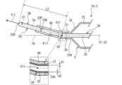
- FIG. 2 is an enlarged cross-sectional view of the distal end portion of the balloon catheter 1A. It is a figure which shows the relationship of the rigidity of the 1st part Q1, the 2nd part Q2, and the 3rd part Q3 of 1 A of balloon catheters.
- FIG. 2 is an explanatory diagram of a first example of the operation of the balloon catheter 1A.
- FIG. 2 is an explanatory diagram of a first example of the operation of the balloon catheter 1A.
- FIG. 2 is an explanatory diagram of a first example of the operation of the balloon catheter 1A. It is explanatory drawing of the 1st example and the 2nd example of the example of operation of balloon catheter 1A.
- FIG. 3 is an explanatory diagram of a second example of the operation of the balloon catheter 1A.
- FIG. 3 is an explanatory diagram of a second example of the operation of the balloon catheter 1A. It is a figure showing balloon catheter 1B. It is a figure showing balloon catheter 1C.
- Embodiments of the balloon catheter 1 (balloon catheters 1A to 1C) according to the present invention will be described with reference to the drawings.
- the drawings referred to are used to explain technical features that may be adopted by the present invention.
- the configuration of the device described is not intended to be limiting, but is merely an illustrative example.
- the balloon catheter 1A will be described with reference to FIGS. 1 to 3.
- the balloon catheter 1A includes a shaft body 20, a balloon body 30, and a covering portion 40.
- the shaft body 20 has a tubular shape and has a bent portion 26 which will be described later.
- the balloon body 30 is inflatable and deflated and is connected to the shaft body 20.
- the covering portion 40 covers a bending region 2R, which will be described later, of the shaft body 20.
- the shaft body 20 One side of both ends of the shaft body 20 is referred to as the "tip side.” The other side of both ends of the shaft body 20 is referred to as the “base end side.”
- the direction extending along the shaft body 20 is referred to as the “stretching direction.”
- the axis passing through the center of the shaft body 20 and extending in the stretching direction is referred to as a central axis C1.
- the radial direction centered on the central axis C1 is simply referred to as the "radial direction.”
- a cross section taken along a plane perpendicular to the central axis C1 is simply referred to as a "cross section.”
- the side closer to the central axis C1 in the radial direction is referred to as the “inner side”
- the side farther away from the central axis C1 is referred to as the “outer side”.
- the circumferential direction centered on the central axis C1 is simply referred to as the "circumferential direction.”
- the shaft body 20 has a shaft main body portion 2A and a tip 2B.
- the shaft main body portion 2A is formed by an outer tube 21 and an inner tube 22, each of which has an inner cavity.
- the outer tube 21 and the inner tube 22 each have flexibility.
- the inner diameter of the outer tube 21 is larger than the outer diameter of the inner tube 22.
- the inner tube 22 is arranged in the inner cavity of the outer tube 21 except for a predetermined portion on the distal end side.
- a predetermined portion on the distal side of the inner tube 22 protrudes toward the distal end from an end on the distal side of the outer tube 21 (hereinafter referred to as "distal end portion 21D").
- the distal end of the inner tube 22 (hereinafter referred to as the “distal end 22D”) is disposed closer to the distal end than the distal end 21D of the outer tube 21.
- the predetermined portion on the distal end side of the inner tube 22 will be referred to as the "protruding portion 225.”
- the proximal end of the outer tube 21 is referred to as a “first proximal end 21P.”
- the proximal end of the inner tube 22 is referred to as a “first proximal end 22P.”
- a hub is connected to at least the first base end portion 21P.
- the materials for the outer tube 21 and the inner tube 22 are not particularly limited, but polyamide resin is used as an example.
- the compressed fluid supplied from the hub flows through the inner cavity of the outer tube 21 other than the inner cavity of the inner tube 22.
- a guide wire G (see FIG. 4, etc.) is inserted into the inner lumen of the inner tube 22.
- the tip 2B is provided in the inner tube 22 of the shaft main body 2A.
- Chip 2B has a rod shape.
- the cross-sectional shape of the chip 2B is circular.
- the outer diameter of the tip 2B is the same as the outer diameter of the inner tube 22.
- the proximal end of the tip 2B (hereinafter referred to as the "proximal end 23P") is connected to the distal end 22D of the inner tube 22.
- the tip 2B extends from the tip portion 22D toward the tip side along the stretching direction.
- the tip end of the tip 2B is referred to as a "first tip 23D.”
- the first tip 23D of the tip 2B has a hemispherical shape and is rounded.
- a through hole extending along the stretching direction is provided at the center of the chip 2B.
- a guide wire G is inserted through the through hole.
- the material of the chip 2B is not particularly limited, but rubber is used as an example.
- the rigidity of the tip 2B is smaller than the rigidity of the shaft main body 2A. Therefore, the tip 2B is softer than the shaft body 2A.
- the balloon body 30 includes at least the balloon 3.
- the balloon 3 can be deformed between a deflated state and an expanded state by changing its internal pressure depending on whether compressed fluid is supplied by a hub (not shown).
- Figure 1 shows the balloon 3 in an inflated state.
- a plurality of wings are formed on the balloon 3 in the deflated state.
- the balloon 3 is connected to the shaft body 20 near the first tip 23D.
- a distal end connection section 31 a distal end connection section 32, an inflatable section 33, a proximal end connection section 34, and a proximal end connection section 35 are defined.
- the inflatable portion 33 has a cylindrical shape whose diameter is approximately the same in the stretching direction in the inflated state.
- the distal end of the inflatable portion 33 is referred to as a "distal end 33D," and the proximal end is referred to as a "proximal end 33P.”
- the length of the expansion part 33 in the stretching direction is, for example, 13 mm.
- the distal end connecting portion 32 extends from the distal end portion 33D toward the distal end side while decreasing in diameter.
- the proximal end connecting portion 34 extends from the proximal end portion 33P toward the proximal end side while decreasing in diameter.
- the length of the distal end connecting portion 32 and the proximal end connecting portion 34 in the extending direction is, for example, 3 mm each.
- the tip connecting portion 31 is provided on the side of the tip connecting portion 32 opposite to the side that connects with the expansion portion 33.
- the distal end connecting portion 31 is a portion of the shaft body 20 that is proximal to the first distal end portion 23D, more specifically, a portion of the outer surface of the inner tube 22 of the shaft body 20 that is proximal to the distal end portion 22D. It is connected to laterally spaced parts by heat welding.
- the part of the inner tube 22 to which the tip connection part 31 of the balloon 3 is connected will be referred to as the "first connection part 226.”
- the end of the tip connecting portion 31 opposite to the side connecting to the tip connecting portion 32 is referred to as a “second tip portion 3D”.
- the second tip 3D corresponds to the tip end of the balloon 3.
- the length of the tip connecting portion 31 in the extending direction is, for example, 1.5 mm.
- the proximal connecting portion 35 is provided on the side of the proximal connecting portion 34 opposite to the side that connects with the inflatable portion 33.
- the proximal connecting portion 35 is a portion of the shaft body 20 that is spaced away from the first connecting portion 226 toward the proximal side, more specifically, a portion of the outer surface of the outer tube 21 of the shaft body 20 near the distal end portion 21D. It is connected to the part by heat welding.
- the part of the outer tube 21 to which the proximal end connection part 35 of the balloon 3 is connected will be referred to as the "second connection part 216."
- the end portion of the proximal end connecting portion 35 on the opposite side to the side connected to the proximal end connecting portion 34 is referred to as a “second proximal end portion 3P”.
- the second proximal end portion 3P corresponds to the end portion of the balloon 3 on the proximal side.
- the length of the proximal end connecting portion 35 in the extending direction is, for example, 2.5 mm.
- the balloon 3 extends between the second distal end 3D and the second proximal end 3P, and covers the protruding portion 225 of the inner tube 22 from the outside.
- the length between the second distal end 3D and the second proximal end 3P of the balloon 3 is expressed as L1.
- the length L1 corresponds to the sum of the lengths of the distal end connecting portion 31, the distal end connecting portion 32, the inflatable portion 33, the proximal end connecting portion 34, and the proximal end connecting portion 35 in the respective stretching directions, and is 23 mm as an example.
- the material of the balloon 3 is not particularly limited, but polyamide resin or polyamide elastomer resin is used as an example.
- the axis extending through the center of the balloon 3 is referred to as the "central axis C2.”
- the central axis C2 overlaps a portion of the central axis C1 extending through the center of the shaft body 20, more specifically, the central axis C1 in the protruding portion 225 of the inner tube 22.
- an axis extending linearly toward the distal end along a portion where the central axes C1 and C2 overlap is referred to as a "reference axis Cb.”
- the shaft main body portion 2A of the shaft body 20 is bent at a portion slightly closer to the distal end than the first connecting portion 226 to which the distal end connecting portion 31 of the balloon 3 is connected.
- this portion will be referred to as the "bent portion 26.”
- the bent portion 26 is formed between the first tip portion 23D of the shaft body 20 and the first connecting portion 226, more specifically, between the tip portion 22D of the shaft body portion 2A of the shaft body 20 and the first connecting portion 226.
- L2 is, for example, 1 cm. Note that the length L2 is not limited to 1 cm, but may be 1 cm or more.
- a portion of the central axis C1 of the shaft body 20 that is closer to the tip than the bent portion 26 is referred to as a "partial axis Ca.”
- the partial axis Ca is inclined with respect to the reference axis Cb.
- the position of the intersection X11 between the partial axis Ca and the reference axis Cb coincides with the bent portion 26 in the stretching direction.
- the angle formed by the reference axis Cb and the partial axis Ca is referred to as a "bending angle ⁇ 11."
- the bending angle ⁇ 11 is, for example, 30°.
- the direction extending along the stretching direction through the first tip 23D of the tip 2B and facing the side opposite to the bending portion 26 with respect to the first tip 23D is referred to as a "bending direction Y11."
- the inner and outer portions have different thicknesses.
- the inner portion indicates a portion of the bent portion 26 that is close to the center of bending.
- the outer portion indicates the portion of the bent portion 26 that is far from the center of bending.
- the thickness of the inner part is written as d1
- the thickness of the outer part is written as d2.
- the thickness d2 is thinner than the thickness d1 (d1>d2). Therefore, the inner portion of the shaft body portion 2A is thicker than the outer portion.
- a covering portion 40 is provided in the shaft body 20 on the distal side of the first connecting portion 226 to which the distal end connecting portion 31 of the balloon 3 is connected.
- the covering portion 40 has a cylindrical shape.
- the covering portion 40 covers a portion of the shaft body 20 including at least the bent portion 26 from the outside.
- the proximal end of the cover 40 contacts the second tip 3D of the balloon 3.
- the distal end of the cover 40 is located on the distal side of the distal end 22D of the shaft body 2A and the proximal end 23P of the tip 2B.
- the covering part 40 covers a part of the shaft body 20 on the distal end side of the shaft main body part 2A, and a part of the tip 2B on the proximal end side.
- the region of the shaft body 20 covered by the covering portion 40 will be referred to as a bending region 2R.
- the bent region 2R includes a bent portion 26.
- the material of the covering part 40 is not particularly limited, but polyether block amide is used as an example.
- the thickness of the cover 40 is greater than the thickness of the inner tube 22. Therefore, the rigidity of the covering portion 40 is greater than the rigidity of the shaft body 20.
- the thickness of the covering portion 40 does not have to be uniform.
- the thickness of the cover 40 may gradually increase from the distal end to the proximal end.
- the rigidity of the cover 40 may gradually increase from the distal end to the proximal end.
- the first portion Q1 is a portion of the balloon catheter 1A that is closer to the distal end than the bending region 2R in the stretching direction.
- the first portion Q1 includes a portion of the tip 2B of the shaft body 20.
- the second portion Q2 is a portion of the balloon catheter 1A that overlaps with the bending region 2R in the stretching direction.
- the second portion Q2 includes a portion of the shaft body portion 2A of the shaft body 20, a portion of the tip 2B, and the covering portion 40.
- the third portion Q3 is a portion of the balloon catheter 1A that is closer to the proximal end than the bending region 2R in the stretching direction.
- the third portion Q3 includes a part of the shaft main body portion 2A and the balloon 3.
- the rigidity of the first portion Q1 of the balloon catheter 1A is referred to as "first rigidity G1.”
- the stiffness of the second portion Q2 of the balloon catheter 1A is referred to as “second stiffness G2.”
- the stiffness of the third portion Q3 of the balloon catheter 1A is referred to as “third stiffness G3.”
- the second stiffness G2 is larger than the first stiffness G1
- the third stiffness G3 is larger than the second stiffness G2 (G1 ⁇ G2 ⁇ G3).
- the respective rigidities (second rigidity G2, third rigidity G3) of the second portion Q2 and the third portion Q3 are not uniform in the stretching direction.
- the second portion Q2 having the second rigidity G2 includes a portion Q21 including a portion of the tip 2B and the covering portion 40, and a portion Q21 including a portion of the shaft body portion 2A and the covering portion 40 in the stretching direction.
- the third portion Q3 includes, in the stretching direction, a portion including the balloon 3 and the inner tube 22, a portion including the balloon 3, the inner tube 22, and the outer tube 21, and an inner portion.
- the first portion Q1 includes only the chip 2B, and the first rigidity G1 matches the rigidity of the chip 2B. Therefore, the first stiffness G1 is uniform in the stretching direction.
- Balloon catheter 1A is manufactured by the following method. A bent rod-shaped mandrel is prepared and inserted into the lumen of the inner tube 22. In this state, the inner tube 22 is bent. Next, the outer tube 21 is placed outside the inner tube 22, and the balloon 3 is placed on the protruding portion 225 of the inner tube 22.
- the outer tube 21, inner tube 22, and balloon 3 are attached to a welding device and heated. Thereby, the tip connection portion 31 of the balloon 3 is connected to the first connection portion 226 of the inner tube 22. Further, the proximal end connection portion 35 of the balloon 3 is connected to the second connection portion 216 of the outer tube 21 .
- the tip 2B is connected to the tip 22D of the inner tube 22, and the shaft body 20 is formed.
- a portion of the shaft body 20 that includes the bent portion 26 is covered with a covering portion 40, and the covering portion 40 is thermally welded to the shaft body 20 by heating.
- the balloon catheter 1A is manufactured.
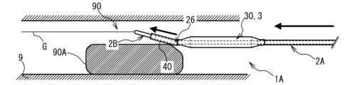
- FIGS. 4 to 9 A first example of the operation of the balloon catheter 1A will be described with reference to FIGS. 4 to 9.
- a case will be illustrated in which the balloon catheter 1A is used to dilate a stenotic lesion (not shown) that has occurred in a part of the inner wall of the blood vessel 9.
- an obstacle 90A such as a calcified inner wall or an indwelled stent is placed on the proximal side of the stenotic lesion.
- the diameter of the lumen of the blood vessel 9 becomes smaller at the location where the obstacle 90A is placed.
- the portion of the lumen of the blood vessel 9 whose diameter is reduced due to the obstruction 90A will be referred to as the "narrow lumen 90.”
- the guide wire G is inserted into the blood vessel 9.
- a balloon catheter 1A including a deflated balloon 3 is prepared.
- a portion of the balloon catheter 1A that includes at least the balloon 3 is placed within the blood vessel 9.
- a guide wire G is inserted through the shaft body 20 of the balloon catheter 1A.
- the balloon catheter 1A is pushed into the blood vessel 9 along the guide wire G by operating the shaft body 20 (see FIG. 1) of the balloon catheter 1A.
- the balloon catheter 1A moves distally within the vessel 9 toward the stenotic lesion with the balloon 3 placed at the front in the moving direction.
- the tip 2B of the balloon catheter 1A comes into contact with the obstacle 90A before the balloon 3 reaches the stenotic lesion.
- the tip 2B contacts the obstacle 90A in a direction in which the reference axis Cb of the balloon catheter 1A intersects the obstacle 90A. Movement of the balloon catheter 1A to the distal side is temporarily restricted by the obstacle 90A.
- the shaft body 20 is operated, and the balloon catheter 1A is further pushed into the blood vessel 9.
- the tip 2B of the balloon catheter 1A since the first tip 23D of the tip 2B of the balloon catheter 1A is rounded, the tip 2B does not get caught on the obstacle 90A, as shown in FIG.
- the shaft main body portion 2A is bent at the bending portion 26, the balloon catheter 1A is bent so that the bending direction Y11 is directed away from the obstacle 90A in response to the force with which the balloon catheter 1A is pushed into the blood vessel 9. Rotate to.
- the tip 2B and the balloon 3 move toward the narrow lumen 90, as shown in FIG. As shown in FIG. 8, the tip 2B moves distally through the narrow lumen 90.
- the balloon 3 overcomes the obstacle 90A, passes through the narrow lumen 90, and moves distally.
- the movement of the balloon catheter 1A is stopped.
- supply of compressed fluid to the balloon 3 is started, and the balloon 3 is in an expanded state.
- the inflated balloon 3 dilates the stenotic lesion.
- a second example of the operation of the balloon catheter 1A will be described with reference to FIGS. 10 and 11.
- the difference from the first example is the arrangement of the reference axis Cb when the chip 2B contacts the obstacle 90A.
- the reference axis Cb of the balloon catheter 1A does not intersect with the obstacle 90A.
- the shaft body 20 is operated, and the balloon catheter 1A is further pushed into the blood vessel 9. Note that since the first tip 23D of the tip 2B of the balloon catheter 1A is rounded, the tip 2B does not get caught on the obstacle 90A. Further, since the shaft main body portion 2A is bent at the bending portion 26, the balloon catheter 1A rotates about the central axis C1 as shown in FIG. do. The bending direction Y11 changes in a direction away from the obstacle 90A.
- the subsequent behavior of the balloon catheter 1A is similar to that of the first example shown in FIGS. 7 to 9.
- the tip 2B and the balloon 3 move toward the narrow lumen 90 (see FIG. 7).
- the tip 2B passes through the narrow lumen 90 and moves distally (see FIG. 8).
- the balloon 3 overcomes the obstacle 90A and moves distally through the narrow lumen 90 (see FIG. 9).
- the balloon 3 becomes inflated and dilates the stenotic lesion.
- the shaft body 20 of the balloon catheter 1A is bent at a bending portion 26. Therefore, when the tip 2B comes into contact with the obstacle 90A, the user can easily direct the bending direction Y11 away from the obstacle 90A by simply pushing the balloon catheter 1A into the blood vessel 9. It becomes possible. Therefore, the balloon catheter 1A allows the balloon 3 to easily reach the stenotic lesion located on the distal side of the obstacle 90A.
- the rigidity of the second portion Q2 of the shaft body 20 that overlaps with the bending region 2R is equal to the stiffness of the first portion Q1 of the shaft body 20 that is closer to the first tip portion 23D than the bending region 2R. (first rigidity G1). Note that the greater the rigidity of the shaft body 20, the more stably it can be maintained in the bent state. In other words, the shaft body 20 is stably maintained in a bent state with the bent portion 26 of the second portion Q2, and is difficult to return to a straightly extended state. Therefore, the balloon catheter 1A can stably maintain the function of allowing the balloon 3 to overcome the obstacle 90A over a long period of time.
- the rigidity (third rigidity G3) of the third portion Q3, which is a portion of the shaft body 20 closer to the first base end portions 21P and 22P than the bending region 2R, is even greater than the second rigidity G2. Therefore, the balloon catheter 1A can achieve good pushability when being pushed into the blood vessel 9. Therefore, the user can efficiently push the balloon catheter 1A having the shaft body 20 including the bent portion 26 toward the stenotic lesion within the blood vessel 9. Thereby, the user can easily operate the balloon catheter 1A so that the balloon 3 can overcome the obstacle 90A in the blood vessel 9 and reach the stenotic lesion.
- the shaft body 20 has a shaft main body 2A provided with a bent portion 26 and a tip 2B having a lower rigidity than the shaft main body 2A. That is, in the balloon catheter 1A, the bent portion 26 is provided in the shaft main body portion 2A, which has relatively high rigidity. Therefore, the balloon catheter 1A can stably maintain the state in which the shaft main body portion 2A is bent at the bending portion 26. Furthermore, by making the rigidity of the tip 2B relatively small, the balloon catheter 1A can prevent the first tip 23D of the tip 2B from damaging the inner wall of the blood vessel 9 when the shaft body 20 moves.
- the balloon catheter 1A has a covering portion 40 that covers a portion of the shaft body 20 that includes the bent portion 26.
- the covering portion 40 can stably maintain the state in which the shaft body 20 is bent at the bending portion 26.
- the tip 2B When the first tip 23D contacts the obstacle 90A when the balloon catheter 1A is pushed into the blood vessel 9, the tip 2B receives force from the obstacle 90A.
- the first tip 23D of the tip 2B is rounded.
- the balloon catheter 1A automatically changes the orientation of the bending direction Y11 so that the balloon 3 can easily overcome the obstacle 90A. Therefore, the user can change the orientation of the bending direction Y11 so that the balloon 3 can easily overcome the obstacle 90A without operating the shaft body 20.
- the thickness d2 of the outer portion of the bent portion 26 is thinner than the thickness d1 of the inner portion of the bent portion 26.
- the balloon catheter 1A can stably maintain the state in which the shaft body 20 is bent at the bending portion 26.
- the length L2 in the extending direction from the first tip 23D of the shaft body 20 to the bent portion 26 is 1 cm or more. In this case, the user can easily operate the balloon catheter 1A so that the balloon 3 can overcome the obstacle 90A in the vessel 9 and reach the stenotic lesion.
- Each value is an example, and other values may be used.
- a portion of the shaft body 20 between the first tip portion 23D and the bent portion 26 may be curved.
- the bent portion 26 does not need to be provided in the vicinity of the first connecting portion 226 of the inner tube 22 to which the tip connecting portion 31 of the balloon 3 is connected.
- the bent portion 26 may be provided near the distal end portion 22D of the inner tube 22.
- a member for increasing the rigidity of the third portion Q3 of the balloon catheter 1A may be further provided.
- the shaft body 20 may be provided with an auxiliary body extending between the second tip 3D of the balloon 3 and the first base ends 21P, 22P of the shaft body 20.
- the auxiliary body may have a wire shape or may be an annular braided tube.
- the bent portion 26 may be provided on the tip 2B of the shaft body 20.
- the shaft body 2A and tip 2B of the shaft body 20 may have the same rigidity.
- the first tip 23D of the tip 2B is not rounded and may be angular.
- the shaft body 20 may have only the shaft body portion 2A without the tip 2B.
- the shaft main body portion 2A may protrude further toward the distal end than the distal end of the covering portion 40.
- the tip end of the shaft main body 2A may be angular or rounded.
- the covering part 40 covers only the part of the inner tube 22 of the shaft body 20 that is closer to the distal end than the first connecting part 226 to which the distal end connecting part 31 of the balloon 3 is connected, and does not need to cover a part of the tip 2B. .
- the proximal end of the covering part 40 may cover the distal end connection part 31 of the balloon 3 from the outside.
- the tip end of the cover 40 may be thinner toward the tip so that no step is formed between it and the chip 2B.
- the cover 40 may have the function of a radiopaque marker. In this case, the user can push the balloon catheter 1A while grasping the position of the bent part 26 by checking the position of the cover part 40 in the body.
- the balloon catheter 1A does not need to have the covering part 40.
- a portion of the inner tube 22 of the shaft body 20 that is closer to the distal end than the first connecting portion 226 to which the distal end connecting portion 31 of the balloon 3 is connected may be defined as the bent region 2R including the bent portion 26.
- the thickness d1 of the inner portion of the bent portion 26 may be thinner than the thickness d2 of the outer portion of the bent portion 26, or the thicknesses d1 and d2 may be the same.
- the process of the balloon 3 getting over the obstacle 90A in the blood vessel 9 was described.
- the balloon 3 can overcome the curved part of the blood vessel 9 and reach the stenotic lesion by the same operation as in the first or second example. It can be reached.
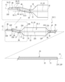
- the shaft main body portion 2A of the shaft body 20 has a portion (hereinafter referred to as “bent portion 27”) slightly closer to the distal end than the first connecting portion 226 to which the distal end connecting portion 31 of the balloon 3 connects, and a distal end portion to which the tip 2B connects. It is bent at a portion slightly closer to the proximal end than the portion 22D (hereinafter referred to as the “bent portion 28”).
- the bent portions 27 and 28 are both connected between the first distal end portion 23D of the shaft body 20 and the first connection portion 226, more specifically, between the distal end portion 22D of the shaft body portion 2A of the shaft body 20 and the first connection. 226.
- the portion sandwiched between the bent portions 27 and 28 is referred to as a "partial axis Ca(1).”
- a portion of the central axis C1 of the shaft body 20 that is closer to the tip than the bent portion 28 is referred to as a "partial axis Ca(2).”
- An axis extending linearly toward the distal end along the overlap between the central axis C2 and the central axis C1 extending through the center of the balloon 3 is referred to as a "reference axis Cb(1).”
- the axis extending linearly toward the tip side along the partial axis Ca(1) is referred to as a "reference axis Cb(2).”
- the partial axis Ca(1) is inclined with respect to the reference axis Cb(1).
- the angle formed by the reference axis Cb(1) and the partial axis Ca(1) is referred to as "bending angle ⁇ 21.”
- the bending angle ⁇ 21 is, for example, 30°.
- Partial axis Ca(2) is inclined with respect to reference axis Cb(2).
- the angle formed by the reference axis Cb (2) and the partial axis Ca (2) is referred to as "bending angle ⁇ 22".
- the bending angle ⁇ 22 is, for example, 30°.
- the bending angles ⁇ 21 and ⁇ 22 are equal.
- the shaft body 20 of the balloon catheter 1B has two bent portions (bent portions 27 and 28).
- the user can easily operate the balloon catheter 1B so that the balloon 3 reaches the stenotic lesion by climbing over the obstacle 90A.
- the user can easily operate the balloon catheter 1B so that the balloon 3 reaches the stenotic lesion by climbing over the plurality of curved portions.
- the values of the bending angles ⁇ 21 and ⁇ 22 are merely examples, and other values may be used.
- the bending angles ⁇ 21 and ⁇ 22 may be different.
- the number of bent portions provided on the shaft body 20 is not limited to two, and may be three or more.
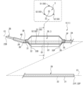
- Balloon catheter 1C differs from balloon catheter 1A in that balloon body 30 includes elements 51, 52, and 53 (hereinafter referred to as "element 50" if not distinguished from each other) in addition to balloon 3.
- the element 50 has a triangular prism shape and extends in the stretching direction along the outer surface of the balloon 3.
- the elements 51, 52, 53 are arranged at equal intervals in the circumferential direction along the outer surface of the balloon 3.
- One of the three sides of the element 50 connects to the outer surface of the balloon 3.
- the width of the element 50 in the circumferential direction becomes narrower toward the outside, and the outside is pointed.
- the stiffness of the element 50 is greater than the stiffness of the balloon 3.
- the position of the distal end of the element 50 coincides with the position of the second distal end 3D of the balloon 3 in the stretching direction.
- the position of the proximal end of the element 50 coincides with the position of the second proximal end 3P of the balloon 3 in the stretching direction.
- the element 50 extends between the second distal end 3D and the second proximal end 3P of the balloon 3.
- the balloon catheter 1C When the balloon 3 reaches the stenotic lesion of the vessel 9 and is inflated, the balloon catheter 1C causes the element 50 to bite into the stenotic lesion. Thereby, the balloon catheter 1C can suppress the position of the balloon 3 from shifting relative to the stenotic lesion when the balloon 3 is inflated. Further, the balloon catheter 1C can cut a stenotic lesion using the element 50. Due to these, the balloon catheter 1C can efficiently dilate the stenotic lesion according to the inflation of the balloon 3.
- the rigidity of the portion overlapping with the element 50 can be increased in the third portion Q3 (see FIG. 3), which is the portion on the proximal side of the bending region 2R. That is, in the balloon catheter 1C, the first portion Q1 (see FIG. 3), which is a portion on the distal side of the bending region 2R, and the second portion Q2 (see FIG. 3), which is a portion overlapping with the bending region 2R, A configuration in which the third portion Q3 has high rigidity can be easily realized by the element 50 of the balloon body 30. Therefore, the balloon catheter 1C can achieve good pushability due to the element 50 of the balloon body 30.
- the element 50 can increase the rigidity over the entire region between the second distal end 3D and the second proximal end 3P of the balloon 3. Therefore, when the balloon catheter 1C is pushed into the blood vessel 9, the balloon 3 can be prevented from being bent, and at the same time, good pushability can be achieved by the element 50.
- the number of elements 50 is not limited to three, and may be one, two, four or more.
- the element 50 may extend between the distal end 33D and the proximal end 33P of the inflation section 33 of the balloon 3. Alternatively, the element 50 may extend further toward the distal end than the second distal end portion 3D. In this case, the distal end of the element 50 may be placed near the bent portion 26.
- the stiffness of the element 50 may be the same as the stiffness of the balloon 3 or may be smaller than the stiffness of the balloon 3.
- the element 50 may be provided on the inner surface of the balloon 3.
- the outer surface of the balloon 3 is smooth and does not need to protrude outward at the portion where the element 50 is provided.
- a member for increasing the rigidity of a portion of the balloon catheter 1C closer to the proximal end than the balloon 3 may be further provided.
- an auxiliary body may be provided in a portion of the shaft body 20 that is closer to the proximal end than the second proximal end portion 3P of the balloon 3.
- the auxiliary body may have a wire shape or may be an annular braided tube.
- the element 50 may be made of the same material as the balloon 3. In this case, the rigidity of the element 50 may be increased by making the molecular orientation of the element 50 different from that of the balloon 3.
Landscapes
- Health & Medical Sciences (AREA)
- Life Sciences & Earth Sciences (AREA)
- Heart & Thoracic Surgery (AREA)
- Engineering & Computer Science (AREA)
- Biophysics (AREA)
- Pulmonology (AREA)
- Anesthesiology (AREA)
- Biomedical Technology (AREA)
- Hematology (AREA)
- Animal Behavior & Ethology (AREA)
- General Health & Medical Sciences (AREA)
- Public Health (AREA)
- Veterinary Medicine (AREA)
- Child & Adolescent Psychology (AREA)
- Media Introduction/Drainage Providing Device (AREA)
Abstract
Un corps de tige (20) du cathéter à ballonnet (1A) selon l'invention présente une région de courbure (2R) comprenant au moins une section de courbure (26) dans une partie entre une première section pointe (23D) et une première section liaison (226). Dans la direction d'étirement du cathéter à ballonnet (1A), la rigidité d'une première partie (Q1) qui est plus proche de la première section pointe (23D) que la région de courbure (2R) représente une première rigidité (G1), la rigidité d'une partie (Q2) qui chevauche la région de courbure (2R) représente une deuxième rigidité (G2), et la rigidité d'une troisième partie (Q3) qui est plus proche d'une première section de base que la région de courbure (2R) représente une troisième rigidité (G3). La deuxième rigidité (G2) est supérieure à la première rigidité (G1), et la troisième rigidité (G3) est supérieure à la deuxième rigidité (G2).
Applications Claiming Priority (2)
| Application Number | Priority Date | Filing Date | Title |
|---|---|---|---|
| JP2022-123322 | 2022-08-02 | ||
| JP2022123322 | 2022-08-02 |
Publications (1)
| Publication Number | Publication Date |
|---|---|
| WO2024029203A1 true WO2024029203A1 (fr) | 2024-02-08 |
Family
ID=89849257
Family Applications (1)
| Application Number | Title | Priority Date | Filing Date |
|---|---|---|---|
| PCT/JP2023/021750 WO2024029203A1 (fr) | 2022-08-02 | 2023-06-12 | Cathéter à ballonnet |
Country Status (1)
| Country | Link |
|---|---|
| WO (1) | WO2024029203A1 (fr) |
Citations (4)
| Publication number | Priority date | Publication date | Assignee | Title |
|---|---|---|---|---|
| JPH021292A (ja) * | 1988-06-01 | 1990-01-05 | Terumo Corp | カテーテルチューブ |
| JP2005125101A (ja) * | 2003-10-23 | 2005-05-19 | Cordis Corp | 操作可能なバルーンカテーテル |
| JP2008200317A (ja) * | 2007-02-21 | 2008-09-04 | Goodman Co Ltd | バルーンカテーテル |
| WO2022102766A1 (fr) * | 2020-11-16 | 2022-05-19 | 株式会社カネカ | Ballonnet pour cathéter à ballonnet |
-
2023
- 2023-06-12 WO PCT/JP2023/021750 patent/WO2024029203A1/fr unknown
Patent Citations (4)
| Publication number | Priority date | Publication date | Assignee | Title |
|---|---|---|---|---|
| JPH021292A (ja) * | 1988-06-01 | 1990-01-05 | Terumo Corp | カテーテルチューブ |
| JP2005125101A (ja) * | 2003-10-23 | 2005-05-19 | Cordis Corp | 操作可能なバルーンカテーテル |
| JP2008200317A (ja) * | 2007-02-21 | 2008-09-04 | Goodman Co Ltd | バルーンカテーテル |
| WO2022102766A1 (fr) * | 2020-11-16 | 2022-05-19 | 株式会社カネカ | Ballonnet pour cathéter à ballonnet |
Similar Documents
| Publication | Publication Date | Title |
|---|---|---|
| US10207083B2 (en) | Balloon catheter and method for manufacturing balloon | |
| US6113579A (en) | Catheter tip designs and methods for improved stent crossing | |
| US7189229B2 (en) | Balloon alignment and collapsing system | |
| JP5237572B2 (ja) | バルーンカテーテル及びその製造方法 | |
| WO2020195697A1 (fr) | Cathéter à ballonnet | |
| JP2005021684A (ja) | 自動センタリング先端部を備えたバルーンカテーテル | |
| US20220088354A1 (en) | Balloon catheter | |
| WO2024029203A1 (fr) | Cathéter à ballonnet | |
| JP6749847B2 (ja) | バルーンカテーテル | |
| US10532191B2 (en) | Catheter | |
| WO2020255923A1 (fr) | Cathéter à ballonnet | |
| JP7148308B2 (ja) | バルーンカテーテル | |
| WO2024042978A1 (fr) | Ballonnet pour cathéter à ballonnet et cathéter à ballonnet pourvu de celui-ci | |
| WO2022137764A1 (fr) | Ballonnet pour cathéter à ballonnet | |
| WO2022137763A1 (fr) | Ballonnet pour cathéter à ballonnet | |
| JP7465696B2 (ja) | バルーンカテーテル | |
| WO2024106402A1 (fr) | Ballonnet de cathéter à ballonnet, cathéter à ballonnet équipé de celui-ci, et procédé de fabrication de cathéter à ballonnet | |
| JP7460294B2 (ja) | バルーンカテーテル | |
| JP2020039376A (ja) | バルーンカテーテル | |
| WO2023157533A1 (fr) | Cathéter à ballonnet | |
| WO2023079906A1 (fr) | Ballonnet pour cathéter à ballonnet | |
| US20240108867A1 (en) | Balloon catheter | |
| WO2023157535A1 (fr) | Cathéter à ballon | |
| WO2024042977A1 (fr) | Ballonnet d'utilisation de cathéter à ballonnet, et cathéter à ballonnet le comprenant | |
| WO2024106083A1 (fr) | Ballonnet pour cathéter à ballonnet, et cathéter à ballonnet |
Legal Events
| Date | Code | Title | Description |
|---|---|---|---|
| 121 | Ep: the epo has been informed by wipo that ep was designated in this application |
Ref document number: 23849763 Country of ref document: EP Kind code of ref document: A1 |