WO2024029203A1 - Balloon catheter - Google Patents
Balloon catheter Download PDFInfo
- Publication number
- WO2024029203A1 WO2024029203A1 PCT/JP2023/021750 JP2023021750W WO2024029203A1 WO 2024029203 A1 WO2024029203 A1 WO 2024029203A1 JP 2023021750 W JP2023021750 W JP 2023021750W WO 2024029203 A1 WO2024029203 A1 WO 2024029203A1
- Authority
- WO
- WIPO (PCT)
- Prior art keywords
- balloon
- balloon catheter
- shaft body
- tip
- stiffness
- Prior art date
Links
- 238000005452 bending Methods 0.000 claims abstract description 67
- 210000004204 blood vessel Anatomy 0.000 description 36
- 230000003902 lesion Effects 0.000 description 25
- 230000002966 stenotic effect Effects 0.000 description 22
- 238000010586 diagram Methods 0.000 description 5
- 239000000463 material Substances 0.000 description 5
- 238000000034 method Methods 0.000 description 4
- 230000000694 effects Effects 0.000 description 3
- 239000012530 fluid Substances 0.000 description 3
- 238000003466 welding Methods 0.000 description 3
- 230000009194 climbing Effects 0.000 description 2
- 230000003247 decreasing effect Effects 0.000 description 2
- 229920001971 elastomer Polymers 0.000 description 2
- 229920006122 polyamide resin Polymers 0.000 description 2
- 239000004952 Polyamide Substances 0.000 description 1
- 229920002614 Polyether block amide Polymers 0.000 description 1
- 239000000806 elastomer Substances 0.000 description 1
- 238000010438 heat treatment Methods 0.000 description 1
- 238000004519 manufacturing process Methods 0.000 description 1
- 239000003550 marker Substances 0.000 description 1
- 229920002647 polyamide Polymers 0.000 description 1
- 239000011347 resin Substances 0.000 description 1
- 229920005989 resin Polymers 0.000 description 1
Images


Classifications
-
- A—HUMAN NECESSITIES
- A61—MEDICAL OR VETERINARY SCIENCE; HYGIENE
- A61M—DEVICES FOR INTRODUCING MEDIA INTO, OR ONTO, THE BODY; DEVICES FOR TRANSDUCING BODY MEDIA OR FOR TAKING MEDIA FROM THE BODY; DEVICES FOR PRODUCING OR ENDING SLEEP OR STUPOR
- A61M25/00—Catheters; Hollow probes
-
- A—HUMAN NECESSITIES
- A61—MEDICAL OR VETERINARY SCIENCE; HYGIENE
- A61M—DEVICES FOR INTRODUCING MEDIA INTO, OR ONTO, THE BODY; DEVICES FOR TRANSDUCING BODY MEDIA OR FOR TAKING MEDIA FROM THE BODY; DEVICES FOR PRODUCING OR ENDING SLEEP OR STUPOR
- A61M25/00—Catheters; Hollow probes
- A61M25/10—Balloon catheters
Definitions
- the present invention relates to a balloon catheter.
- a balloon catheter is known as a medical device that dilates a stenotic lesion in a blood vessel by inflating a balloon. Furthermore, various techniques have been proposed for quickly bringing a balloon to the vicinity of a stenotic lesion (see, for example, Patent Document 1).
- An object of the present invention is to provide a balloon catheter that can easily overcome curved portions of blood vessels and obstacles within blood vessels.
- the balloon catheter according to the present invention includes a shaft body extending between a first distal end and a first proximal end, and a balloon body connected to the vicinity of the first distal end of the shaft body, the balloon catheter comprising: A second distal end portion is connected to a first connecting portion that is a portion spaced apart from the first proximal end portion of the shaft body toward the first proximal end portion, and The second proximal end portion is connected to a second connecting portion that is a portion spaced apart from the proximal end portion, and the balloon body extends between the second distal end portion and the second proximal end portion.
- the shaft body has a bending region including at least one bending part in a portion between the first tip part and the first connection part, and In the stretching direction, which is the direction along the center of the shaft body, the stiffness of the first portion, which is the part closer to the first tip than the bending region, is the first stiffness;
- the stiffness of a second portion that overlaps with the bending region in the direction is the second stiffness, and is a portion of the balloon catheter that is closer to the first proximal end than the bending region in the stretching direction.
- the third part has a third rigidity, the second rigidity is greater than the first rigidity, and the third rigidity is greater than the second rigidity.
- the rigidity of the second portion of the balloon catheter that overlaps with the bending region is greater than the rigidity of the first portion of the balloon catheter, which is the portion of the balloon catheter that is closer to the first tip than the bending region. Note that the greater the rigidity, the more stably the bent state can be maintained. Therefore, the balloon catheter can stably maintain the state in which the shaft body included in the second portion is bent at the bending portion of the bending region.
- the rigidity of the third portion of the balloon catheter which is the portion closer to the first proximal end than the second portion, is greater than the rigidity of the first and second portions. Therefore, the balloon catheter achieves good pushability. Therefore, the user can efficiently push the balloon catheter having the bent portion toward the lesion. As a result, the user can easily operate the balloon catheter so that the balloon body reaches the diseased area by overcoming the curved portion of the blood vessel and obstacles within the blood vessel.
- the shaft body includes a shaft body having a lumen, and a tip provided at an end of the shaft body closest to the first tip and having a lower rigidity than the shaft body.
- the bending portion may be provided in the shaft main body.
- the balloon catheter can stably maintain a state in which the shaft body is bent at the bending portion by forming a bending portion in the shaft main body portion having relatively high rigidity.
- the tip can prevent the first tip from damaging the inner wall of the blood vessel when the shaft body moves.
- the shaft body may include a covering portion that covers at least the bending region.
- the cover can stably maintain the state in which the shaft body is bent at the bending portion of the bending region.
- the balloon body includes an inflatable balloon and an element provided on the balloon, and the balloon body may have greater rigidity than the balloon.
- the balloon catheter facilitates the relationship that the stiffness in the third portion (third stiffness) is greater than the stiffness in the first and second portions (first stiffness, second stiffness) by the elements of the balloon body. can be realized. Therefore, the balloon catheter can achieve good pushability due to the elements of the balloon body.
- the element may extend between the second distal end and the second base end.
- the balloon catheter can have increased rigidity over the entire region in the stretching direction of the balloon body. Therefore, the balloon catheter can achieve good pushability.
- the bending region may include two or more of the bending parts.
- the balloon catheter allows the balloon body to reach the lesion by adjusting the bending directions of the two or more bent portions of the shaft body according to the curved portion of the blood vessel or the shape of the obstruction within the blood vessel. can.
- the first tip of the shaft body may be rounded. In this case, if the first tip comes into contact with an obstacle when the balloon catheter is pushed into a blood vessel, the force that the shaft receives from the obstacle causes the first tip of the shaft to easily overcome the obstacle. change direction. Therefore, the user can change the orientation of the first tip of the shaft body without having to manually rotate the shaft body.
- the thickness of the outer portion of the bent portion of the shaft body may be thinner than the thickness of the inner portion.
- the balloon catheter can stably maintain the state in which the shaft body is bent at the bending portion.
- the length of the shaft body from the first tip end to the bent part in the stretching direction may be 1 cm or more.
- the user can easily operate the balloon catheter so that the balloon body reaches the diseased area by overcoming the curved portion of the blood vessel and the obstacles within the blood vessel.
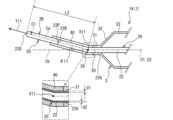
- FIG. 2 is an enlarged cross-sectional view of the distal end portion of the balloon catheter 1A. It is a figure which shows the relationship of the rigidity of the 1st part Q1, the 2nd part Q2, and the 3rd part Q3 of 1 A of balloon catheters.
- FIG. 2 is an explanatory diagram of a first example of the operation of the balloon catheter 1A.
- FIG. 2 is an explanatory diagram of a first example of the operation of the balloon catheter 1A.
- FIG. 2 is an explanatory diagram of a first example of the operation of the balloon catheter 1A. It is explanatory drawing of the 1st example and the 2nd example of the example of operation of balloon catheter 1A.
- FIG. 3 is an explanatory diagram of a second example of the operation of the balloon catheter 1A.
- FIG. 3 is an explanatory diagram of a second example of the operation of the balloon catheter 1A. It is a figure showing balloon catheter 1B. It is a figure showing balloon catheter 1C.
- Embodiments of the balloon catheter 1 (balloon catheters 1A to 1C) according to the present invention will be described with reference to the drawings.
- the drawings referred to are used to explain technical features that may be adopted by the present invention.
- the configuration of the device described is not intended to be limiting, but is merely an illustrative example.
- the balloon catheter 1A will be described with reference to FIGS. 1 to 3.
- the balloon catheter 1A includes a shaft body 20, a balloon body 30, and a covering portion 40.
- the shaft body 20 has a tubular shape and has a bent portion 26 which will be described later.
- the balloon body 30 is inflatable and deflated and is connected to the shaft body 20.
- the covering portion 40 covers a bending region 2R, which will be described later, of the shaft body 20.
- the shaft body 20 One side of both ends of the shaft body 20 is referred to as the "tip side.” The other side of both ends of the shaft body 20 is referred to as the “base end side.”
- the direction extending along the shaft body 20 is referred to as the “stretching direction.”
- the axis passing through the center of the shaft body 20 and extending in the stretching direction is referred to as a central axis C1.
- the radial direction centered on the central axis C1 is simply referred to as the "radial direction.”
- a cross section taken along a plane perpendicular to the central axis C1 is simply referred to as a "cross section.”
- the side closer to the central axis C1 in the radial direction is referred to as the “inner side”
- the side farther away from the central axis C1 is referred to as the “outer side”.
- the circumferential direction centered on the central axis C1 is simply referred to as the "circumferential direction.”
- the shaft body 20 has a shaft main body portion 2A and a tip 2B.
- the shaft main body portion 2A is formed by an outer tube 21 and an inner tube 22, each of which has an inner cavity.
- the outer tube 21 and the inner tube 22 each have flexibility.
- the inner diameter of the outer tube 21 is larger than the outer diameter of the inner tube 22.
- the inner tube 22 is arranged in the inner cavity of the outer tube 21 except for a predetermined portion on the distal end side.
- a predetermined portion on the distal side of the inner tube 22 protrudes toward the distal end from an end on the distal side of the outer tube 21 (hereinafter referred to as "distal end portion 21D").
- the distal end of the inner tube 22 (hereinafter referred to as the “distal end 22D”) is disposed closer to the distal end than the distal end 21D of the outer tube 21.
- the predetermined portion on the distal end side of the inner tube 22 will be referred to as the "protruding portion 225.”
- the proximal end of the outer tube 21 is referred to as a “first proximal end 21P.”
- the proximal end of the inner tube 22 is referred to as a “first proximal end 22P.”
- a hub is connected to at least the first base end portion 21P.
- the materials for the outer tube 21 and the inner tube 22 are not particularly limited, but polyamide resin is used as an example.
- the compressed fluid supplied from the hub flows through the inner cavity of the outer tube 21 other than the inner cavity of the inner tube 22.
- a guide wire G (see FIG. 4, etc.) is inserted into the inner lumen of the inner tube 22.
- the tip 2B is provided in the inner tube 22 of the shaft main body 2A.
- Chip 2B has a rod shape.
- the cross-sectional shape of the chip 2B is circular.
- the outer diameter of the tip 2B is the same as the outer diameter of the inner tube 22.
- the proximal end of the tip 2B (hereinafter referred to as the "proximal end 23P") is connected to the distal end 22D of the inner tube 22.
- the tip 2B extends from the tip portion 22D toward the tip side along the stretching direction.
- the tip end of the tip 2B is referred to as a "first tip 23D.”
- the first tip 23D of the tip 2B has a hemispherical shape and is rounded.
- a through hole extending along the stretching direction is provided at the center of the chip 2B.
- a guide wire G is inserted through the through hole.
- the material of the chip 2B is not particularly limited, but rubber is used as an example.
- the rigidity of the tip 2B is smaller than the rigidity of the shaft main body 2A. Therefore, the tip 2B is softer than the shaft body 2A.
- the balloon body 30 includes at least the balloon 3.
- the balloon 3 can be deformed between a deflated state and an expanded state by changing its internal pressure depending on whether compressed fluid is supplied by a hub (not shown).
- Figure 1 shows the balloon 3 in an inflated state.
- a plurality of wings are formed on the balloon 3 in the deflated state.
- the balloon 3 is connected to the shaft body 20 near the first tip 23D.
- a distal end connection section 31 a distal end connection section 32, an inflatable section 33, a proximal end connection section 34, and a proximal end connection section 35 are defined.
- the inflatable portion 33 has a cylindrical shape whose diameter is approximately the same in the stretching direction in the inflated state.
- the distal end of the inflatable portion 33 is referred to as a "distal end 33D," and the proximal end is referred to as a "proximal end 33P.”
- the length of the expansion part 33 in the stretching direction is, for example, 13 mm.
- the distal end connecting portion 32 extends from the distal end portion 33D toward the distal end side while decreasing in diameter.
- the proximal end connecting portion 34 extends from the proximal end portion 33P toward the proximal end side while decreasing in diameter.
- the length of the distal end connecting portion 32 and the proximal end connecting portion 34 in the extending direction is, for example, 3 mm each.
- the tip connecting portion 31 is provided on the side of the tip connecting portion 32 opposite to the side that connects with the expansion portion 33.
- the distal end connecting portion 31 is a portion of the shaft body 20 that is proximal to the first distal end portion 23D, more specifically, a portion of the outer surface of the inner tube 22 of the shaft body 20 that is proximal to the distal end portion 22D. It is connected to laterally spaced parts by heat welding.
- the part of the inner tube 22 to which the tip connection part 31 of the balloon 3 is connected will be referred to as the "first connection part 226.”
- the end of the tip connecting portion 31 opposite to the side connecting to the tip connecting portion 32 is referred to as a “second tip portion 3D”.
- the second tip 3D corresponds to the tip end of the balloon 3.
- the length of the tip connecting portion 31 in the extending direction is, for example, 1.5 mm.
- the proximal connecting portion 35 is provided on the side of the proximal connecting portion 34 opposite to the side that connects with the inflatable portion 33.
- the proximal connecting portion 35 is a portion of the shaft body 20 that is spaced away from the first connecting portion 226 toward the proximal side, more specifically, a portion of the outer surface of the outer tube 21 of the shaft body 20 near the distal end portion 21D. It is connected to the part by heat welding.
- the part of the outer tube 21 to which the proximal end connection part 35 of the balloon 3 is connected will be referred to as the "second connection part 216."
- the end portion of the proximal end connecting portion 35 on the opposite side to the side connected to the proximal end connecting portion 34 is referred to as a “second proximal end portion 3P”.
- the second proximal end portion 3P corresponds to the end portion of the balloon 3 on the proximal side.
- the length of the proximal end connecting portion 35 in the extending direction is, for example, 2.5 mm.
- the balloon 3 extends between the second distal end 3D and the second proximal end 3P, and covers the protruding portion 225 of the inner tube 22 from the outside.
- the length between the second distal end 3D and the second proximal end 3P of the balloon 3 is expressed as L1.
- the length L1 corresponds to the sum of the lengths of the distal end connecting portion 31, the distal end connecting portion 32, the inflatable portion 33, the proximal end connecting portion 34, and the proximal end connecting portion 35 in the respective stretching directions, and is 23 mm as an example.
- the material of the balloon 3 is not particularly limited, but polyamide resin or polyamide elastomer resin is used as an example.
- the axis extending through the center of the balloon 3 is referred to as the "central axis C2.”
- the central axis C2 overlaps a portion of the central axis C1 extending through the center of the shaft body 20, more specifically, the central axis C1 in the protruding portion 225 of the inner tube 22.
- an axis extending linearly toward the distal end along a portion where the central axes C1 and C2 overlap is referred to as a "reference axis Cb.”
- the shaft main body portion 2A of the shaft body 20 is bent at a portion slightly closer to the distal end than the first connecting portion 226 to which the distal end connecting portion 31 of the balloon 3 is connected.
- this portion will be referred to as the "bent portion 26.”
- the bent portion 26 is formed between the first tip portion 23D of the shaft body 20 and the first connecting portion 226, more specifically, between the tip portion 22D of the shaft body portion 2A of the shaft body 20 and the first connecting portion 226.
- L2 is, for example, 1 cm. Note that the length L2 is not limited to 1 cm, but may be 1 cm or more.
- a portion of the central axis C1 of the shaft body 20 that is closer to the tip than the bent portion 26 is referred to as a "partial axis Ca.”
- the partial axis Ca is inclined with respect to the reference axis Cb.
- the position of the intersection X11 between the partial axis Ca and the reference axis Cb coincides with the bent portion 26 in the stretching direction.
- the angle formed by the reference axis Cb and the partial axis Ca is referred to as a "bending angle ⁇ 11."
- the bending angle ⁇ 11 is, for example, 30°.
- the direction extending along the stretching direction through the first tip 23D of the tip 2B and facing the side opposite to the bending portion 26 with respect to the first tip 23D is referred to as a "bending direction Y11."
- the inner and outer portions have different thicknesses.
- the inner portion indicates a portion of the bent portion 26 that is close to the center of bending.
- the outer portion indicates the portion of the bent portion 26 that is far from the center of bending.
- the thickness of the inner part is written as d1
- the thickness of the outer part is written as d2.
- the thickness d2 is thinner than the thickness d1 (d1>d2). Therefore, the inner portion of the shaft body portion 2A is thicker than the outer portion.
- a covering portion 40 is provided in the shaft body 20 on the distal side of the first connecting portion 226 to which the distal end connecting portion 31 of the balloon 3 is connected.
- the covering portion 40 has a cylindrical shape.
- the covering portion 40 covers a portion of the shaft body 20 including at least the bent portion 26 from the outside.
- the proximal end of the cover 40 contacts the second tip 3D of the balloon 3.
- the distal end of the cover 40 is located on the distal side of the distal end 22D of the shaft body 2A and the proximal end 23P of the tip 2B.
- the covering part 40 covers a part of the shaft body 20 on the distal end side of the shaft main body part 2A, and a part of the tip 2B on the proximal end side.
- the region of the shaft body 20 covered by the covering portion 40 will be referred to as a bending region 2R.
- the bent region 2R includes a bent portion 26.
- the material of the covering part 40 is not particularly limited, but polyether block amide is used as an example.
- the thickness of the cover 40 is greater than the thickness of the inner tube 22. Therefore, the rigidity of the covering portion 40 is greater than the rigidity of the shaft body 20.
- the thickness of the covering portion 40 does not have to be uniform.
- the thickness of the cover 40 may gradually increase from the distal end to the proximal end.
- the rigidity of the cover 40 may gradually increase from the distal end to the proximal end.
- the first portion Q1 is a portion of the balloon catheter 1A that is closer to the distal end than the bending region 2R in the stretching direction.
- the first portion Q1 includes a portion of the tip 2B of the shaft body 20.
- the second portion Q2 is a portion of the balloon catheter 1A that overlaps with the bending region 2R in the stretching direction.
- the second portion Q2 includes a portion of the shaft body portion 2A of the shaft body 20, a portion of the tip 2B, and the covering portion 40.
- the third portion Q3 is a portion of the balloon catheter 1A that is closer to the proximal end than the bending region 2R in the stretching direction.
- the third portion Q3 includes a part of the shaft main body portion 2A and the balloon 3.
- the rigidity of the first portion Q1 of the balloon catheter 1A is referred to as "first rigidity G1.”
- the stiffness of the second portion Q2 of the balloon catheter 1A is referred to as “second stiffness G2.”
- the stiffness of the third portion Q3 of the balloon catheter 1A is referred to as “third stiffness G3.”
- the second stiffness G2 is larger than the first stiffness G1
- the third stiffness G3 is larger than the second stiffness G2 (G1 ⁇ G2 ⁇ G3).
- the respective rigidities (second rigidity G2, third rigidity G3) of the second portion Q2 and the third portion Q3 are not uniform in the stretching direction.
- the second portion Q2 having the second rigidity G2 includes a portion Q21 including a portion of the tip 2B and the covering portion 40, and a portion Q21 including a portion of the shaft body portion 2A and the covering portion 40 in the stretching direction.
- the third portion Q3 includes, in the stretching direction, a portion including the balloon 3 and the inner tube 22, a portion including the balloon 3, the inner tube 22, and the outer tube 21, and an inner portion.
- the first portion Q1 includes only the chip 2B, and the first rigidity G1 matches the rigidity of the chip 2B. Therefore, the first stiffness G1 is uniform in the stretching direction.
- Balloon catheter 1A is manufactured by the following method. A bent rod-shaped mandrel is prepared and inserted into the lumen of the inner tube 22. In this state, the inner tube 22 is bent. Next, the outer tube 21 is placed outside the inner tube 22, and the balloon 3 is placed on the protruding portion 225 of the inner tube 22.
- the outer tube 21, inner tube 22, and balloon 3 are attached to a welding device and heated. Thereby, the tip connection portion 31 of the balloon 3 is connected to the first connection portion 226 of the inner tube 22. Further, the proximal end connection portion 35 of the balloon 3 is connected to the second connection portion 216 of the outer tube 21 .
- the tip 2B is connected to the tip 22D of the inner tube 22, and the shaft body 20 is formed.
- a portion of the shaft body 20 that includes the bent portion 26 is covered with a covering portion 40, and the covering portion 40 is thermally welded to the shaft body 20 by heating.
- the balloon catheter 1A is manufactured.
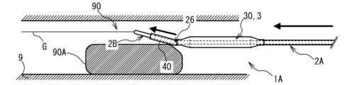
- FIGS. 4 to 9 A first example of the operation of the balloon catheter 1A will be described with reference to FIGS. 4 to 9.
- a case will be illustrated in which the balloon catheter 1A is used to dilate a stenotic lesion (not shown) that has occurred in a part of the inner wall of the blood vessel 9.
- an obstacle 90A such as a calcified inner wall or an indwelled stent is placed on the proximal side of the stenotic lesion.
- the diameter of the lumen of the blood vessel 9 becomes smaller at the location where the obstacle 90A is placed.
- the portion of the lumen of the blood vessel 9 whose diameter is reduced due to the obstruction 90A will be referred to as the "narrow lumen 90.”
- the guide wire G is inserted into the blood vessel 9.
- a balloon catheter 1A including a deflated balloon 3 is prepared.
- a portion of the balloon catheter 1A that includes at least the balloon 3 is placed within the blood vessel 9.
- a guide wire G is inserted through the shaft body 20 of the balloon catheter 1A.
- the balloon catheter 1A is pushed into the blood vessel 9 along the guide wire G by operating the shaft body 20 (see FIG. 1) of the balloon catheter 1A.
- the balloon catheter 1A moves distally within the vessel 9 toward the stenotic lesion with the balloon 3 placed at the front in the moving direction.
- the tip 2B of the balloon catheter 1A comes into contact with the obstacle 90A before the balloon 3 reaches the stenotic lesion.
- the tip 2B contacts the obstacle 90A in a direction in which the reference axis Cb of the balloon catheter 1A intersects the obstacle 90A. Movement of the balloon catheter 1A to the distal side is temporarily restricted by the obstacle 90A.
- the shaft body 20 is operated, and the balloon catheter 1A is further pushed into the blood vessel 9.
- the tip 2B of the balloon catheter 1A since the first tip 23D of the tip 2B of the balloon catheter 1A is rounded, the tip 2B does not get caught on the obstacle 90A, as shown in FIG.
- the shaft main body portion 2A is bent at the bending portion 26, the balloon catheter 1A is bent so that the bending direction Y11 is directed away from the obstacle 90A in response to the force with which the balloon catheter 1A is pushed into the blood vessel 9. Rotate to.
- the tip 2B and the balloon 3 move toward the narrow lumen 90, as shown in FIG. As shown in FIG. 8, the tip 2B moves distally through the narrow lumen 90.
- the balloon 3 overcomes the obstacle 90A, passes through the narrow lumen 90, and moves distally.
- the movement of the balloon catheter 1A is stopped.
- supply of compressed fluid to the balloon 3 is started, and the balloon 3 is in an expanded state.
- the inflated balloon 3 dilates the stenotic lesion.
- a second example of the operation of the balloon catheter 1A will be described with reference to FIGS. 10 and 11.
- the difference from the first example is the arrangement of the reference axis Cb when the chip 2B contacts the obstacle 90A.
- the reference axis Cb of the balloon catheter 1A does not intersect with the obstacle 90A.
- the shaft body 20 is operated, and the balloon catheter 1A is further pushed into the blood vessel 9. Note that since the first tip 23D of the tip 2B of the balloon catheter 1A is rounded, the tip 2B does not get caught on the obstacle 90A. Further, since the shaft main body portion 2A is bent at the bending portion 26, the balloon catheter 1A rotates about the central axis C1 as shown in FIG. do. The bending direction Y11 changes in a direction away from the obstacle 90A.
- the subsequent behavior of the balloon catheter 1A is similar to that of the first example shown in FIGS. 7 to 9.
- the tip 2B and the balloon 3 move toward the narrow lumen 90 (see FIG. 7).
- the tip 2B passes through the narrow lumen 90 and moves distally (see FIG. 8).
- the balloon 3 overcomes the obstacle 90A and moves distally through the narrow lumen 90 (see FIG. 9).
- the balloon 3 becomes inflated and dilates the stenotic lesion.
- the shaft body 20 of the balloon catheter 1A is bent at a bending portion 26. Therefore, when the tip 2B comes into contact with the obstacle 90A, the user can easily direct the bending direction Y11 away from the obstacle 90A by simply pushing the balloon catheter 1A into the blood vessel 9. It becomes possible. Therefore, the balloon catheter 1A allows the balloon 3 to easily reach the stenotic lesion located on the distal side of the obstacle 90A.
- the rigidity of the second portion Q2 of the shaft body 20 that overlaps with the bending region 2R is equal to the stiffness of the first portion Q1 of the shaft body 20 that is closer to the first tip portion 23D than the bending region 2R. (first rigidity G1). Note that the greater the rigidity of the shaft body 20, the more stably it can be maintained in the bent state. In other words, the shaft body 20 is stably maintained in a bent state with the bent portion 26 of the second portion Q2, and is difficult to return to a straightly extended state. Therefore, the balloon catheter 1A can stably maintain the function of allowing the balloon 3 to overcome the obstacle 90A over a long period of time.
- the rigidity (third rigidity G3) of the third portion Q3, which is a portion of the shaft body 20 closer to the first base end portions 21P and 22P than the bending region 2R, is even greater than the second rigidity G2. Therefore, the balloon catheter 1A can achieve good pushability when being pushed into the blood vessel 9. Therefore, the user can efficiently push the balloon catheter 1A having the shaft body 20 including the bent portion 26 toward the stenotic lesion within the blood vessel 9. Thereby, the user can easily operate the balloon catheter 1A so that the balloon 3 can overcome the obstacle 90A in the blood vessel 9 and reach the stenotic lesion.
- the shaft body 20 has a shaft main body 2A provided with a bent portion 26 and a tip 2B having a lower rigidity than the shaft main body 2A. That is, in the balloon catheter 1A, the bent portion 26 is provided in the shaft main body portion 2A, which has relatively high rigidity. Therefore, the balloon catheter 1A can stably maintain the state in which the shaft main body portion 2A is bent at the bending portion 26. Furthermore, by making the rigidity of the tip 2B relatively small, the balloon catheter 1A can prevent the first tip 23D of the tip 2B from damaging the inner wall of the blood vessel 9 when the shaft body 20 moves.
- the balloon catheter 1A has a covering portion 40 that covers a portion of the shaft body 20 that includes the bent portion 26.
- the covering portion 40 can stably maintain the state in which the shaft body 20 is bent at the bending portion 26.
- the tip 2B When the first tip 23D contacts the obstacle 90A when the balloon catheter 1A is pushed into the blood vessel 9, the tip 2B receives force from the obstacle 90A.
- the first tip 23D of the tip 2B is rounded.
- the balloon catheter 1A automatically changes the orientation of the bending direction Y11 so that the balloon 3 can easily overcome the obstacle 90A. Therefore, the user can change the orientation of the bending direction Y11 so that the balloon 3 can easily overcome the obstacle 90A without operating the shaft body 20.
- the thickness d2 of the outer portion of the bent portion 26 is thinner than the thickness d1 of the inner portion of the bent portion 26.
- the balloon catheter 1A can stably maintain the state in which the shaft body 20 is bent at the bending portion 26.
- the length L2 in the extending direction from the first tip 23D of the shaft body 20 to the bent portion 26 is 1 cm or more. In this case, the user can easily operate the balloon catheter 1A so that the balloon 3 can overcome the obstacle 90A in the vessel 9 and reach the stenotic lesion.
- Each value is an example, and other values may be used.
- a portion of the shaft body 20 between the first tip portion 23D and the bent portion 26 may be curved.
- the bent portion 26 does not need to be provided in the vicinity of the first connecting portion 226 of the inner tube 22 to which the tip connecting portion 31 of the balloon 3 is connected.
- the bent portion 26 may be provided near the distal end portion 22D of the inner tube 22.
- a member for increasing the rigidity of the third portion Q3 of the balloon catheter 1A may be further provided.
- the shaft body 20 may be provided with an auxiliary body extending between the second tip 3D of the balloon 3 and the first base ends 21P, 22P of the shaft body 20.
- the auxiliary body may have a wire shape or may be an annular braided tube.
- the bent portion 26 may be provided on the tip 2B of the shaft body 20.
- the shaft body 2A and tip 2B of the shaft body 20 may have the same rigidity.
- the first tip 23D of the tip 2B is not rounded and may be angular.
- the shaft body 20 may have only the shaft body portion 2A without the tip 2B.
- the shaft main body portion 2A may protrude further toward the distal end than the distal end of the covering portion 40.
- the tip end of the shaft main body 2A may be angular or rounded.
- the covering part 40 covers only the part of the inner tube 22 of the shaft body 20 that is closer to the distal end than the first connecting part 226 to which the distal end connecting part 31 of the balloon 3 is connected, and does not need to cover a part of the tip 2B. .
- the proximal end of the covering part 40 may cover the distal end connection part 31 of the balloon 3 from the outside.
- the tip end of the cover 40 may be thinner toward the tip so that no step is formed between it and the chip 2B.
- the cover 40 may have the function of a radiopaque marker. In this case, the user can push the balloon catheter 1A while grasping the position of the bent part 26 by checking the position of the cover part 40 in the body.
- the balloon catheter 1A does not need to have the covering part 40.
- a portion of the inner tube 22 of the shaft body 20 that is closer to the distal end than the first connecting portion 226 to which the distal end connecting portion 31 of the balloon 3 is connected may be defined as the bent region 2R including the bent portion 26.
- the thickness d1 of the inner portion of the bent portion 26 may be thinner than the thickness d2 of the outer portion of the bent portion 26, or the thicknesses d1 and d2 may be the same.
- the process of the balloon 3 getting over the obstacle 90A in the blood vessel 9 was described.
- the balloon 3 can overcome the curved part of the blood vessel 9 and reach the stenotic lesion by the same operation as in the first or second example. It can be reached.
- the shaft main body portion 2A of the shaft body 20 has a portion (hereinafter referred to as “bent portion 27”) slightly closer to the distal end than the first connecting portion 226 to which the distal end connecting portion 31 of the balloon 3 connects, and a distal end portion to which the tip 2B connects. It is bent at a portion slightly closer to the proximal end than the portion 22D (hereinafter referred to as the “bent portion 28”).
- the bent portions 27 and 28 are both connected between the first distal end portion 23D of the shaft body 20 and the first connection portion 226, more specifically, between the distal end portion 22D of the shaft body portion 2A of the shaft body 20 and the first connection. 226.
- the portion sandwiched between the bent portions 27 and 28 is referred to as a "partial axis Ca(1).”
- a portion of the central axis C1 of the shaft body 20 that is closer to the tip than the bent portion 28 is referred to as a "partial axis Ca(2).”
- An axis extending linearly toward the distal end along the overlap between the central axis C2 and the central axis C1 extending through the center of the balloon 3 is referred to as a "reference axis Cb(1).”
- the axis extending linearly toward the tip side along the partial axis Ca(1) is referred to as a "reference axis Cb(2).”
- the partial axis Ca(1) is inclined with respect to the reference axis Cb(1).
- the angle formed by the reference axis Cb(1) and the partial axis Ca(1) is referred to as "bending angle ⁇ 21.”
- the bending angle ⁇ 21 is, for example, 30°.
- Partial axis Ca(2) is inclined with respect to reference axis Cb(2).
- the angle formed by the reference axis Cb (2) and the partial axis Ca (2) is referred to as "bending angle ⁇ 22".
- the bending angle ⁇ 22 is, for example, 30°.
- the bending angles ⁇ 21 and ⁇ 22 are equal.
- the shaft body 20 of the balloon catheter 1B has two bent portions (bent portions 27 and 28).
- the user can easily operate the balloon catheter 1B so that the balloon 3 reaches the stenotic lesion by climbing over the obstacle 90A.
- the user can easily operate the balloon catheter 1B so that the balloon 3 reaches the stenotic lesion by climbing over the plurality of curved portions.
- the values of the bending angles ⁇ 21 and ⁇ 22 are merely examples, and other values may be used.
- the bending angles ⁇ 21 and ⁇ 22 may be different.
- the number of bent portions provided on the shaft body 20 is not limited to two, and may be three or more.
- Balloon catheter 1C differs from balloon catheter 1A in that balloon body 30 includes elements 51, 52, and 53 (hereinafter referred to as "element 50" if not distinguished from each other) in addition to balloon 3.
- the element 50 has a triangular prism shape and extends in the stretching direction along the outer surface of the balloon 3.
- the elements 51, 52, 53 are arranged at equal intervals in the circumferential direction along the outer surface of the balloon 3.
- One of the three sides of the element 50 connects to the outer surface of the balloon 3.
- the width of the element 50 in the circumferential direction becomes narrower toward the outside, and the outside is pointed.
- the stiffness of the element 50 is greater than the stiffness of the balloon 3.
- the position of the distal end of the element 50 coincides with the position of the second distal end 3D of the balloon 3 in the stretching direction.
- the position of the proximal end of the element 50 coincides with the position of the second proximal end 3P of the balloon 3 in the stretching direction.
- the element 50 extends between the second distal end 3D and the second proximal end 3P of the balloon 3.
- the balloon catheter 1C When the balloon 3 reaches the stenotic lesion of the vessel 9 and is inflated, the balloon catheter 1C causes the element 50 to bite into the stenotic lesion. Thereby, the balloon catheter 1C can suppress the position of the balloon 3 from shifting relative to the stenotic lesion when the balloon 3 is inflated. Further, the balloon catheter 1C can cut a stenotic lesion using the element 50. Due to these, the balloon catheter 1C can efficiently dilate the stenotic lesion according to the inflation of the balloon 3.
- the rigidity of the portion overlapping with the element 50 can be increased in the third portion Q3 (see FIG. 3), which is the portion on the proximal side of the bending region 2R. That is, in the balloon catheter 1C, the first portion Q1 (see FIG. 3), which is a portion on the distal side of the bending region 2R, and the second portion Q2 (see FIG. 3), which is a portion overlapping with the bending region 2R, A configuration in which the third portion Q3 has high rigidity can be easily realized by the element 50 of the balloon body 30. Therefore, the balloon catheter 1C can achieve good pushability due to the element 50 of the balloon body 30.
- the element 50 can increase the rigidity over the entire region between the second distal end 3D and the second proximal end 3P of the balloon 3. Therefore, when the balloon catheter 1C is pushed into the blood vessel 9, the balloon 3 can be prevented from being bent, and at the same time, good pushability can be achieved by the element 50.
- the number of elements 50 is not limited to three, and may be one, two, four or more.
- the element 50 may extend between the distal end 33D and the proximal end 33P of the inflation section 33 of the balloon 3. Alternatively, the element 50 may extend further toward the distal end than the second distal end portion 3D. In this case, the distal end of the element 50 may be placed near the bent portion 26.
- the stiffness of the element 50 may be the same as the stiffness of the balloon 3 or may be smaller than the stiffness of the balloon 3.
- the element 50 may be provided on the inner surface of the balloon 3.
- the outer surface of the balloon 3 is smooth and does not need to protrude outward at the portion where the element 50 is provided.
- a member for increasing the rigidity of a portion of the balloon catheter 1C closer to the proximal end than the balloon 3 may be further provided.
- an auxiliary body may be provided in a portion of the shaft body 20 that is closer to the proximal end than the second proximal end portion 3P of the balloon 3.
- the auxiliary body may have a wire shape or may be an annular braided tube.
- the element 50 may be made of the same material as the balloon 3. In this case, the rigidity of the element 50 may be increased by making the molecular orientation of the element 50 different from that of the balloon 3.
Abstract
A shaft body (20) of this balloon catheter (1A) has a bending region (2R) including at least one bending section (26) in a portion between a first tip section (23D) and a first connection section (226). In the stretching direction of the balloon catheter (1A), the stiffness of a first portion (Q1) that is closer to the first tip section (23D) than the bending region (2R) is a first stiffness (G1), the stiffness of a portion (Q2) that overlaps with the bending region (2R) is a second stiffness (G2), and the stiffness of a third portion (Q3) that is closer to a first base section than the bending region (2R) is a third stiffness (G3). The second stiffness (G2) is larger than the first stiffness (G1), and the third stiffness (G3) is larger than the second stiffness (G2).
Description
本発明は、バルーンカテーテルに関する。
The present invention relates to a balloon catheter.
血管内の狭窄病変をバルーンの膨張により拡張する医療機器として、バルーンカテーテルが知られている。又、狭窄病変の近傍までバルーンを速やかに到達させるための技術が各種提案されている(例えば、特許文献1参照)。
A balloon catheter is known as a medical device that dilates a stenotic lesion in a blood vessel by inflating a balloon. Furthermore, various techniques have been proposed for quickly bringing a balloon to the vicinity of a stenotic lesion (see, for example, Patent Document 1).
従来のバルーンカテーテルでは、血管の湾曲部分や血管内の障害物を乗り越えて病変にバルーンを到達させることが難しい。
With conventional balloon catheters, it is difficult to get the balloon to reach the lesion by overcoming curved parts of blood vessels and obstacles within the blood vessels.
本発明の目的は、血管の湾曲部分や血管内の障害物を容易に乗り越えられるバルーンカテーテルを提供することである。
An object of the present invention is to provide a balloon catheter that can easily overcome curved portions of blood vessels and obstacles within blood vessels.
本発明に係るバルーンカテーテルは、第1先端部と第1基端部との間に亘って延びるシャフト体と、前記シャフト体の前記第1先端部の近傍に接続したバルーン体であって、前記シャフト体の前記第1先端部に対して前記第1基端部の側に離隔した部位である第1接続部に、第2先端部が連結し、前記第1接続部に対して前記第1基端部の側に離隔した部位である第2接続部に、第2基端部が連結し、前記第2先端部と前記第2基端部との間に亘って延びるバルーン体とを備えたバルーンカテーテルであって、前記シャフト体は、前記第1先端部と前記第1接続部との間の部分に、屈曲部を少なくとも1つ含む屈曲領域を有し、前記バルーンカテーテルのうち、前記シャフト体の中心に沿った方向である延伸方向において、前記屈曲領域よりも前記第1先端部の側の部分である第1部分の剛性が第1剛性であり、前記バルーンカテーテルのうち、前記延伸方向において前記屈曲領域と重複する部分である第2部分の剛性が第2剛性であり、前記バルーンカテーテルのうち、前記延伸方向において前記屈曲領域よりも前記第1基端部の側の部分である第3部分の剛性が第3剛性であり、前記第1剛性よりも前記第2剛性の方が大きく、且つ、前記第2剛性よりも前記第3剛性の方が大きいことを特徴とする。
The balloon catheter according to the present invention includes a shaft body extending between a first distal end and a first proximal end, and a balloon body connected to the vicinity of the first distal end of the shaft body, the balloon catheter comprising: A second distal end portion is connected to a first connecting portion that is a portion spaced apart from the first proximal end portion of the shaft body toward the first proximal end portion, and The second proximal end portion is connected to a second connecting portion that is a portion spaced apart from the proximal end portion, and the balloon body extends between the second distal end portion and the second proximal end portion. In the balloon catheter, the shaft body has a bending region including at least one bending part in a portion between the first tip part and the first connection part, and In the stretching direction, which is the direction along the center of the shaft body, the stiffness of the first portion, which is the part closer to the first tip than the bending region, is the first stiffness; The stiffness of a second portion that overlaps with the bending region in the direction is the second stiffness, and is a portion of the balloon catheter that is closer to the first proximal end than the bending region in the stretching direction. The third part has a third rigidity, the second rigidity is greater than the first rigidity, and the third rigidity is greater than the second rigidity.
本発明において、バルーンカテーテルのうち屈曲領域と重複する第2部分の剛性は、バルーンカテーテルのうち屈曲領域よりも第1先端部の側の部分である第1部分の剛性よりも大きい。なお、剛性が大きい程、屈曲した状態は安定的に維持される。従って、バルーンカテーテルは、第2部分に含まれるシャフト体が屈曲領域の屈曲部で屈曲した状態を安定的に維持できる。
In the present invention, the rigidity of the second portion of the balloon catheter that overlaps with the bending region is greater than the rigidity of the first portion of the balloon catheter, which is the portion of the balloon catheter that is closer to the first tip than the bending region. Note that the greater the rigidity, the more stably the bent state can be maintained. Therefore, the balloon catheter can stably maintain the state in which the shaft body included in the second portion is bent at the bending portion of the bending region.
又、バルーンカテーテルのうち第2部分よりも第1基端部の側の部分である第3部分の剛性は、第1部分及び第2部分の剛性よりも大きい。従って、バルーンカテーテルは、良好なプッシャビリティを実現する。このためユーザは、屈曲部を有するバルーンカテーテルを、病変に向けて効率良く押し込むことができる。これによりユーザは、血管の湾曲部分や血管内の障害物を乗り越えてバルーン体が病変部に到達するよう、バルーンカテーテルを容易に操作できる。
Further, the rigidity of the third portion of the balloon catheter, which is the portion closer to the first proximal end than the second portion, is greater than the rigidity of the first and second portions. Therefore, the balloon catheter achieves good pushability. Therefore, the user can efficiently push the balloon catheter having the bent portion toward the lesion. As a result, the user can easily operate the balloon catheter so that the balloon body reaches the diseased area by overcoming the curved portion of the blood vessel and obstacles within the blood vessel.
本発明において、前記シャフト体は、内腔を有するシャフト本体部と、前記シャフト本体部のうち前記第1先端部に最も近接する端部に設けられ、前記シャフト本体部よりも剛性が小さいチップとを有し、前記屈曲部は、前記シャフト本体部に設けられてもよい。この場合、バルーンカテーテルは、剛性が相対的に大きいシャフト本体部に屈曲部を形成させることにより、シャフト体が屈曲部で屈曲した状態を安定的に維持できる。又、シャフト体の移動時において第1先端部が血管の内壁を傷つけてしまうことを、チップにより抑制できる。
In the present invention, the shaft body includes a shaft body having a lumen, and a tip provided at an end of the shaft body closest to the first tip and having a lower rigidity than the shaft body. The bending portion may be provided in the shaft main body. In this case, the balloon catheter can stably maintain a state in which the shaft body is bent at the bending portion by forming a bending portion in the shaft main body portion having relatively high rigidity. Further, the tip can prevent the first tip from damaging the inner wall of the blood vessel when the shaft body moves.
本発明において、前記シャフト体の前記屈曲領域を少なくとも覆う覆部を有してもよい。この場合、覆部は、シャフト体が屈曲領域の屈曲部で屈曲した状態を安定的に維持できる。
In the present invention, the shaft body may include a covering portion that covers at least the bending region. In this case, the cover can stably maintain the state in which the shaft body is bent at the bending portion of the bending region.
本発明において、前記バルーン体は、膨縮可能なバルーンと、前記バルーンに設けられたエレメントと、を有し、前記バルーン体の剛性は、前記バルーンの剛性よりも大きくてもよい。この場合、バルーンカテーテルは、第3部分における剛性(第3剛性)が、第1部分及び第2部分における剛性(第1剛性、第2剛性)よりも大きいという関係を、バルーン体のエレメントにより容易に実現できる。従って、バルーンカテーテルは、バルーン体のエレメントにより、良好なプッシャビリティを実現できる。
In the present invention, the balloon body includes an inflatable balloon and an element provided on the balloon, and the balloon body may have greater rigidity than the balloon. In this case, the balloon catheter facilitates the relationship that the stiffness in the third portion (third stiffness) is greater than the stiffness in the first and second portions (first stiffness, second stiffness) by the elements of the balloon body. can be realized. Therefore, the balloon catheter can achieve good pushability due to the elements of the balloon body.
本発明において、前記エレメントは、前記第2先端部と前記第2基端部との間に亘って延びてもよい。この場合、バルーンカテーテルは、バルーン体の延伸方向の全域に亘って、剛性を大きくできる。従って、バルーンカテーテルは、良好なプッシャビリティを実現できる。
In the present invention, the element may extend between the second distal end and the second base end. In this case, the balloon catheter can have increased rigidity over the entire region in the stretching direction of the balloon body. Therefore, the balloon catheter can achieve good pushability.
本発明において、前記屈曲領域は、2つ以上の前記屈曲部を含んでいてもよい。この場合、バルーンカテーテルは、シャフト体の2つ以上の屈曲部における屈曲方向を、血管の湾曲部分や血管内の障害物の形状に応じて調整することにより、バルーン体を病変に到達させることができる。
In the present invention, the bending region may include two or more of the bending parts. In this case, the balloon catheter allows the balloon body to reach the lesion by adjusting the bending directions of the two or more bent portions of the shaft body according to the curved portion of the blood vessel or the shape of the obstruction within the blood vessel. can.
本発明において、前記シャフト体の前記第1先端部が丸みを帯びていてもよい。この場合、バルーンカテーテルを血管に押し込んだときに第1先端部が障害物に接触した場合、シャフト体が障害物から受ける力により、シャフト体の第1先端部は、障害物を乗り越えやすいように向きを変える。従ってユーザは、シャフト体を手動で回転させることを要せず、シャフト体の第1先端部の向きを変えることができる。
In the present invention, the first tip of the shaft body may be rounded. In this case, if the first tip comes into contact with an obstacle when the balloon catheter is pushed into a blood vessel, the force that the shaft receives from the obstacle causes the first tip of the shaft to easily overcome the obstacle. change direction. Therefore, the user can change the orientation of the first tip of the shaft body without having to manually rotate the shaft body.
本発明において、前記シャフト体の前記屈曲部の内側部分の厚さよりも外側部分の厚さの方が薄くてもよい。この場合、バルーンカテーテルは、シャフト体が屈曲部で屈曲した状態を安定的に維持できる。
In the present invention, the thickness of the outer portion of the bent portion of the shaft body may be thinner than the thickness of the inner portion. In this case, the balloon catheter can stably maintain the state in which the shaft body is bent at the bending portion.
第1態様において、前記シャフト体の前記第1先端部から前記屈曲部までの間の前記延伸方向の長さは、1cm以上であってもよい。この場合、ユーザは、血管の湾曲部分や血管内の障害物を乗り越えてバルーン体が病変部に到達するよう、バルーンカテーテルを容易に操作できる。
In the first aspect, the length of the shaft body from the first tip end to the bent part in the stretching direction may be 1 cm or more. In this case, the user can easily operate the balloon catheter so that the balloon body reaches the diseased area by overcoming the curved portion of the blood vessel and the obstacles within the blood vessel.
本発明に係るバルーンカテーテル1の実施形態(バルーンカテーテル1A~1C)について、図面を参照して説明する。参照する図面は、本発明が採用しうる技術的特徴を説明するために用いられるものである。記載されている装置の構成等は、それのみに限定する趣旨ではなく、単なる説明例である。
Embodiments of the balloon catheter 1 (balloon catheters 1A to 1C) according to the present invention will be described with reference to the drawings. The drawings referred to are used to explain technical features that may be adopted by the present invention. The configuration of the device described is not intended to be limiting, but is merely an illustrative example.
<第1実施形態(バルーンカテーテル1A)>
図1~図3を参照し、バルーンカテーテル1Aについて説明する。バルーンカテーテル1Aは、シャフト体20、バルーン体30、及び覆部40を有する。シャフト体20は管状を有し、後述する屈曲部26を有する。バルーン体30は膨縮可能であり、シャフト体20に接続する。覆部40は、シャフト体20のうち後述する屈曲領域2Rを覆う。 <First embodiment (balloon catheter 1A)>
Theballoon catheter 1A will be described with reference to FIGS. 1 to 3. The balloon catheter 1A includes a shaft body 20, a balloon body 30, and a covering portion 40. The shaft body 20 has a tubular shape and has a bent portion 26 which will be described later. The balloon body 30 is inflatable and deflated and is connected to the shaft body 20. The covering portion 40 covers a bending region 2R, which will be described later, of the shaft body 20.
図1~図3を参照し、バルーンカテーテル1Aについて説明する。バルーンカテーテル1Aは、シャフト体20、バルーン体30、及び覆部40を有する。シャフト体20は管状を有し、後述する屈曲部26を有する。バルーン体30は膨縮可能であり、シャフト体20に接続する。覆部40は、シャフト体20のうち後述する屈曲領域2Rを覆う。 <First embodiment (
The
シャフト体20の両端のうち一方側を、「先端側」という。シャフト体20の両端のうち他方側を、「基端側」という。シャフト体20に沿って延びる方向を、「延伸方向」という。シャフト体20の中心を通って延伸方向に延びる軸を、中心軸C1という。中心軸C1を中心とする半径方向を、単に「半径方向」という。中心軸C1と直交する平面において切断した場合の断面を、単に「断面」という。断面において、半径方向のうち中心軸C1に近接する側を「内側」といい、中心軸C1から離隔する側を「外側」という。中心軸C1を中心とした周方向を、単に「周方向」という。
One side of both ends of the shaft body 20 is referred to as the "tip side." The other side of both ends of the shaft body 20 is referred to as the "base end side." The direction extending along the shaft body 20 is referred to as the "stretching direction." The axis passing through the center of the shaft body 20 and extending in the stretching direction is referred to as a central axis C1. The radial direction centered on the central axis C1 is simply referred to as the "radial direction." A cross section taken along a plane perpendicular to the central axis C1 is simply referred to as a "cross section." In the cross section, the side closer to the central axis C1 in the radial direction is referred to as the "inner side", and the side farther away from the central axis C1 is referred to as the "outer side". The circumferential direction centered on the central axis C1 is simply referred to as the "circumferential direction."
<シャフト体20>
シャフト体20は、シャフト本体部2A及びチップ2Bを有する。 <Shaft body 20>
Theshaft body 20 has a shaft main body portion 2A and a tip 2B.
シャフト体20は、シャフト本体部2A及びチップ2Bを有する。 <
The
図1に示すように、シャフト本体部2Aは、それぞれが内腔を有する外側チューブ21及び内側チューブ22により形成される。外側チューブ21及び内側チューブ22は、それぞれ可撓性を有する。外側チューブ21の内径は、内側チューブ22の外径よりも大きい。内側チューブ22は、先端側の所定部分を除き、外側チューブ21の内腔に配置される。内側チューブ22の先端側の所定部分は、外側チューブ21の先端側の端部(以下、「先端部21D」という。)から先端側に向けて突出する。内側チューブ22の先端側の端部(以下、「先端部22D」という。)は、外側チューブ21の先端部21Dよりも先端側に配置される。
As shown in FIG. 1, the shaft main body portion 2A is formed by an outer tube 21 and an inner tube 22, each of which has an inner cavity. The outer tube 21 and the inner tube 22 each have flexibility. The inner diameter of the outer tube 21 is larger than the outer diameter of the inner tube 22. The inner tube 22 is arranged in the inner cavity of the outer tube 21 except for a predetermined portion on the distal end side. A predetermined portion on the distal side of the inner tube 22 protrudes toward the distal end from an end on the distal side of the outer tube 21 (hereinafter referred to as "distal end portion 21D"). The distal end of the inner tube 22 (hereinafter referred to as the "distal end 22D") is disposed closer to the distal end than the distal end 21D of the outer tube 21.
以下、内側チューブ22の先端側の所定部分を、「突出部分225」という。外側チューブ21の基端側の端部を、「第1基端部21P」という。内側チューブ22の基端側の端部を、「第1基端部22P」という。少なくとも第1基端部21Pには、ハブが接続される。外側チューブ21及び内側チューブ22の材料は特に限定されないが、一例としてポリアミド系樹脂が用いられる。
Hereinafter, the predetermined portion on the distal end side of the inner tube 22 will be referred to as the "protruding portion 225." The proximal end of the outer tube 21 is referred to as a "first proximal end 21P." The proximal end of the inner tube 22 is referred to as a "first proximal end 22P." A hub is connected to at least the first base end portion 21P. The materials for the outer tube 21 and the inner tube 22 are not particularly limited, but polyamide resin is used as an example.
外側チューブ21の内腔のうち、内側チューブ22の内腔以外の空間には、ハブから供給される圧縮流体が通流する。内側チューブ22の内腔には、ガイドワイヤG(図4等参照)が挿通される。
The compressed fluid supplied from the hub flows through the inner cavity of the outer tube 21 other than the inner cavity of the inner tube 22. A guide wire G (see FIG. 4, etc.) is inserted into the inner lumen of the inner tube 22.
図2に示すように、チップ2Bは、シャフト本体部2Aの内側チューブ22に設けられる。チップ2Bは棒状を有する。チップ2Bの断面形状は円形である。チップ2Bの外径は、内側チューブ22の外径と同一である。チップ2Bの基端側の端部(以下、「基端部23P」という。)は、内側チューブ22の先端部22Dに接続する。チップ2Bは、先端部22Dから先端側に向けて、延伸方向に沿って延びる。チップ2Bの先端側の端部を、「第1先端部23D」という。
As shown in FIG. 2, the tip 2B is provided in the inner tube 22 of the shaft main body 2A. Chip 2B has a rod shape. The cross-sectional shape of the chip 2B is circular. The outer diameter of the tip 2B is the same as the outer diameter of the inner tube 22. The proximal end of the tip 2B (hereinafter referred to as the "proximal end 23P") is connected to the distal end 22D of the inner tube 22. The tip 2B extends from the tip portion 22D toward the tip side along the stretching direction. The tip end of the tip 2B is referred to as a "first tip 23D."
チップ2Bの第1先端部23Dは半球状を有し、丸みを帯びている。チップ2Bの中心には、延伸方向に沿って伸びる貫通孔が設けられる。貫通孔には、ガイドワイヤGが挿通される。チップ2Bの材料は特に限定されないが、一例としてゴムが用いられる。チップ2Bの剛性は、シャフト本体部2Aの剛性よりも小さい。このため、チップ2Bはシャフト本体部2Aよりも柔らかい。
The first tip 23D of the tip 2B has a hemispherical shape and is rounded. A through hole extending along the stretching direction is provided at the center of the chip 2B. A guide wire G is inserted through the through hole. The material of the chip 2B is not particularly limited, but rubber is used as an example. The rigidity of the tip 2B is smaller than the rigidity of the shaft main body 2A. Therefore, the tip 2B is softer than the shaft body 2A.
<バルーン体30>
図1に示すように、バルーン体30は、バルーン3を少なくとも含む。バルーン3は、非図示のハブによる圧縮流体の供給の有無に応じて内圧が変化することにより、収縮状態と膨張状態との間で変形可能である。図1は、膨張状態のバルーン3を示す。一方、収縮状態のバルーン3には複数の羽根が形成される。 <Balloon body 30>
As shown in FIG. 1, the balloon body 30 includes at least theballoon 3. The balloon 3 can be deformed between a deflated state and an expanded state by changing its internal pressure depending on whether compressed fluid is supplied by a hub (not shown). Figure 1 shows the balloon 3 in an inflated state. On the other hand, a plurality of wings are formed on the balloon 3 in the deflated state.
図1に示すように、バルーン体30は、バルーン3を少なくとも含む。バルーン3は、非図示のハブによる圧縮流体の供給の有無に応じて内圧が変化することにより、収縮状態と膨張状態との間で変形可能である。図1は、膨張状態のバルーン3を示す。一方、収縮状態のバルーン3には複数の羽根が形成される。 <Balloon body 30>
As shown in FIG. 1, the balloon body 30 includes at least the
バルーン3は、シャフト体20のうち第1先端部23Dの近傍に接続する。バルーン3において、先端接続部31、先端連結部32、膨張部33、基端連結部34、及び基端接続部35が定義される。
The balloon 3 is connected to the shaft body 20 near the first tip 23D. In the balloon 3, a distal end connection section 31, a distal end connection section 32, an inflatable section 33, a proximal end connection section 34, and a proximal end connection section 35 are defined.
膨張部33は、膨張状態において延伸方向に亘って径が略同一となる筒状を有する。膨張部33の先端側の端部を「先端部33D」といい、基端側の端部を「基端部33P」という。膨張部33の延伸方向の長さは、一例として13mmである。先端連結部32は、膨張状態において先端部33Dから先端側に向けて縮径しながら延びる。基端連結部34は、膨張状態において基端部33Pから基端側に向けて縮径しながら延びる。先端連結部32及び基端連結部34の延伸方向の長さは、一例として、それぞれ3mmである。
The inflatable portion 33 has a cylindrical shape whose diameter is approximately the same in the stretching direction in the inflated state. The distal end of the inflatable portion 33 is referred to as a "distal end 33D," and the proximal end is referred to as a "proximal end 33P." The length of the expansion part 33 in the stretching direction is, for example, 13 mm. In the expanded state, the distal end connecting portion 32 extends from the distal end portion 33D toward the distal end side while decreasing in diameter. In the expanded state, the proximal end connecting portion 34 extends from the proximal end portion 33P toward the proximal end side while decreasing in diameter. The length of the distal end connecting portion 32 and the proximal end connecting portion 34 in the extending direction is, for example, 3 mm each.
先端接続部31は、先端連結部32のうち膨張部33と連結する側と反対側に設けられる。先端接続部31は、シャフト体20のうち第1先端部23Dに対して基端に離隔した部位、より詳細には、シャフト体20の内側チューブ22の外面のうち先端部22Dに対して基端側に離隔した部位に、熱溶着によって接続される。以下、内側チューブ22のうちバルーン3の先端接続部31が接続される部位を、「第1接続部226」という。先端接続部31のうち先端連結部32と接続する側と反対側の端部を、「第2先端部3D」という。第2先端部3Dは、バルーン3の先端側の端部に対応する。先端接続部31の延伸方向の長さは、一例として1.5mmである。
The tip connecting portion 31 is provided on the side of the tip connecting portion 32 opposite to the side that connects with the expansion portion 33. The distal end connecting portion 31 is a portion of the shaft body 20 that is proximal to the first distal end portion 23D, more specifically, a portion of the outer surface of the inner tube 22 of the shaft body 20 that is proximal to the distal end portion 22D. It is connected to laterally spaced parts by heat welding. Hereinafter, the part of the inner tube 22 to which the tip connection part 31 of the balloon 3 is connected will be referred to as the "first connection part 226." The end of the tip connecting portion 31 opposite to the side connecting to the tip connecting portion 32 is referred to as a “second tip portion 3D”. The second tip 3D corresponds to the tip end of the balloon 3. The length of the tip connecting portion 31 in the extending direction is, for example, 1.5 mm.
基端接続部35は、基端連結部34のうち膨張部33と連結する側と反対側に設けられる。基端接続部35は、シャフト体20のうち第1接続部226に対して基端側に離隔した部位、より詳細には、シャフト体20の外側チューブ21の外面のうち先端部21Dの近傍の部位に、熱溶着によって接続される。以下、外側チューブ21のうちバルーン3の基端接続部35が接続される部位を、「第2接続部216」という。基端接続部35のうち基端連結部34と接続する側と反対側の端部を、「第2基端部3P」という。第2基端部3Pは、バルーン3の基端側の端部に対応する。基端接続部35の延伸方向の長さは、一例として2.5mmである。
The proximal connecting portion 35 is provided on the side of the proximal connecting portion 34 opposite to the side that connects with the inflatable portion 33. The proximal connecting portion 35 is a portion of the shaft body 20 that is spaced away from the first connecting portion 226 toward the proximal side, more specifically, a portion of the outer surface of the outer tube 21 of the shaft body 20 near the distal end portion 21D. It is connected to the part by heat welding. Hereinafter, the part of the outer tube 21 to which the proximal end connection part 35 of the balloon 3 is connected will be referred to as the "second connection part 216." The end portion of the proximal end connecting portion 35 on the opposite side to the side connected to the proximal end connecting portion 34 is referred to as a “second proximal end portion 3P”. The second proximal end portion 3P corresponds to the end portion of the balloon 3 on the proximal side. The length of the proximal end connecting portion 35 in the extending direction is, for example, 2.5 mm.
バルーン3は、第2先端部3Dと第2基端部3Pとの間に亘って延び、内側チューブ22の突出部分225を外側から覆う。バルーン3の第2先端部3Dと第2基端部3Pとの間の長さを、L1と表記する。長さL1は、先端接続部31、先端連結部32、膨張部33、基端連結部34、及び基端接続部35のそれぞれの延伸方向の長さの和と一致し、一例として23mmである。バルーン3の材料は特に限定されないが、一例としてポリアミド系樹脂やポリアミドエラストマー系樹脂が用いられる。
The balloon 3 extends between the second distal end 3D and the second proximal end 3P, and covers the protruding portion 225 of the inner tube 22 from the outside. The length between the second distal end 3D and the second proximal end 3P of the balloon 3 is expressed as L1. The length L1 corresponds to the sum of the lengths of the distal end connecting portion 31, the distal end connecting portion 32, the inflatable portion 33, the proximal end connecting portion 34, and the proximal end connecting portion 35 in the respective stretching directions, and is 23 mm as an example. . The material of the balloon 3 is not particularly limited, but polyamide resin or polyamide elastomer resin is used as an example.
バルーン3の中心を通って延びる軸を、「中心軸C2」という。中心軸C2は、シャフト体20の中心を通って延びる中心軸C1の一部、より詳細には、内側チューブ22の突出部分225における中心軸C1と重複する。図2に示すように、中心軸C1、C2が重複する部分に沿って先端側に直線状に延びる軸を、「基準軸Cb」という。
The axis extending through the center of the balloon 3 is referred to as the "central axis C2." The central axis C2 overlaps a portion of the central axis C1 extending through the center of the shaft body 20, more specifically, the central axis C1 in the protruding portion 225 of the inner tube 22. As shown in FIG. 2, an axis extending linearly toward the distal end along a portion where the central axes C1 and C2 overlap is referred to as a "reference axis Cb."
<屈曲部26>
図2に示すように、シャフト体20のシャフト本体部2Aは、バルーン3の先端接続部31が接続する第1接続部226よりも僅かに先端側の部分で屈曲する。以下、この部分を「屈曲部26」という。屈曲部26は、シャフト体20の第1先端部23Dと第1接続部226との間、より詳細には、シャフト体20のシャフト本体部2Aの先端部22Dと第1接続部226との間に位置する。シャフト体20の第1先端部23Dと屈曲部26との間の長さを、L2と表記する。長さL2は、一例として1cmである。なお、長さL2は1cmに限定されず、1cm以上であればよい。 <Bending portion 26>
As shown in FIG. 2, the shaftmain body portion 2A of the shaft body 20 is bent at a portion slightly closer to the distal end than the first connecting portion 226 to which the distal end connecting portion 31 of the balloon 3 is connected. Hereinafter, this portion will be referred to as the "bent portion 26." The bent portion 26 is formed between the first tip portion 23D of the shaft body 20 and the first connecting portion 226, more specifically, between the tip portion 22D of the shaft body portion 2A of the shaft body 20 and the first connecting portion 226. Located in The length between the first tip portion 23D of the shaft body 20 and the bent portion 26 is expressed as L2. The length L2 is, for example, 1 cm. Note that the length L2 is not limited to 1 cm, but may be 1 cm or more.
図2に示すように、シャフト体20のシャフト本体部2Aは、バルーン3の先端接続部31が接続する第1接続部226よりも僅かに先端側の部分で屈曲する。以下、この部分を「屈曲部26」という。屈曲部26は、シャフト体20の第1先端部23Dと第1接続部226との間、より詳細には、シャフト体20のシャフト本体部2Aの先端部22Dと第1接続部226との間に位置する。シャフト体20の第1先端部23Dと屈曲部26との間の長さを、L2と表記する。長さL2は、一例として1cmである。なお、長さL2は1cmに限定されず、1cm以上であればよい。 <
As shown in FIG. 2, the shaft
シャフト体20の中心軸C1のうち、屈曲部26よりも先端側の部分を、「部分軸Ca」という。部分軸Caは、基準軸Cbに対して傾斜する。部分軸Caと基準軸Cbとの交点X11の位置は、延伸方向において屈曲部26と一致する。基準軸Cbと部分軸Caとのなす角度を、「屈曲角θ11」という。屈曲角θ11は、一例として30°である。チップ2Bの第1先端部23Dを通って延伸方向に沿って延び、且つ、第1先端部23Dに対して屈曲部26の側と反対側に向かう方向を、「屈曲方向Y11」という。
A portion of the central axis C1 of the shaft body 20 that is closer to the tip than the bent portion 26 is referred to as a "partial axis Ca." The partial axis Ca is inclined with respect to the reference axis Cb. The position of the intersection X11 between the partial axis Ca and the reference axis Cb coincides with the bent portion 26 in the stretching direction. The angle formed by the reference axis Cb and the partial axis Ca is referred to as a "bending angle θ11." The bending angle θ11 is, for example, 30°. The direction extending along the stretching direction through the first tip 23D of the tip 2B and facing the side opposite to the bending portion 26 with respect to the first tip 23D is referred to as a "bending direction Y11."
シャフト本体部2Aの屈曲部26では、内側部分と外側部分とで厚さが相違する。内側部分は、屈曲部26のうち曲げの中心に近い部分を示す。外側部分は、屈曲部26のうち曲げの中心から遠い部分を示す。内側部分の厚さをd1と表記し、外側部分の厚さをd2と表記する。この場合、厚さd1よりも厚さd2の方が薄い(d1>d2)。従って、シャフト本体部2Aは、内側部分の方が外側部分よりも厚さが厚い。
In the bent portion 26 of the shaft main body portion 2A, the inner and outer portions have different thicknesses. The inner portion indicates a portion of the bent portion 26 that is close to the center of bending. The outer portion indicates the portion of the bent portion 26 that is far from the center of bending. The thickness of the inner part is written as d1, and the thickness of the outer part is written as d2. In this case, the thickness d2 is thinner than the thickness d1 (d1>d2). Therefore, the inner portion of the shaft body portion 2A is thicker than the outer portion.
<覆部40>
図1、図2に示すように、シャフト体20のうち、バルーン3の先端接続部31が接続する第1接続部226よりも先端側に、覆部40が設けられる。覆部40は筒状を有する。覆部40は、シャフト体20のうち屈曲部26を少なくとも含む一部分を、外側から覆う。覆部40の基端側の端部は、バルーン3の第2先端部3Dに接触する。覆部40の先端側の端部は、シャフト本体部2Aの先端部22D、及び、チップ2Bの基端部23Pよりも先端側に位置する。従って覆部40は、シャフト体20のうちシャフト本体部2Aの先端側の一部、及び、チップ2Bのうち基端側の一部をそれぞれ覆う。以下、シャフト体20のうち覆部40により覆われる領域を、屈曲領域2Rという。屈曲領域2Rには、屈曲部26が含まれる。 <Coverpart 40>
As shown in FIGS. 1 and 2, a coveringportion 40 is provided in the shaft body 20 on the distal side of the first connecting portion 226 to which the distal end connecting portion 31 of the balloon 3 is connected. The covering portion 40 has a cylindrical shape. The covering portion 40 covers a portion of the shaft body 20 including at least the bent portion 26 from the outside. The proximal end of the cover 40 contacts the second tip 3D of the balloon 3. The distal end of the cover 40 is located on the distal side of the distal end 22D of the shaft body 2A and the proximal end 23P of the tip 2B. Therefore, the covering part 40 covers a part of the shaft body 20 on the distal end side of the shaft main body part 2A, and a part of the tip 2B on the proximal end side. Hereinafter, the region of the shaft body 20 covered by the covering portion 40 will be referred to as a bending region 2R. The bent region 2R includes a bent portion 26.
図1、図2に示すように、シャフト体20のうち、バルーン3の先端接続部31が接続する第1接続部226よりも先端側に、覆部40が設けられる。覆部40は筒状を有する。覆部40は、シャフト体20のうち屈曲部26を少なくとも含む一部分を、外側から覆う。覆部40の基端側の端部は、バルーン3の第2先端部3Dに接触する。覆部40の先端側の端部は、シャフト本体部2Aの先端部22D、及び、チップ2Bの基端部23Pよりも先端側に位置する。従って覆部40は、シャフト体20のうちシャフト本体部2Aの先端側の一部、及び、チップ2Bのうち基端側の一部をそれぞれ覆う。以下、シャフト体20のうち覆部40により覆われる領域を、屈曲領域2Rという。屈曲領域2Rには、屈曲部26が含まれる。 <Cover
As shown in FIGS. 1 and 2, a covering
覆部40の材料は特に限定されないが、一例としてポリエーテルブロックアミドが用いられる。覆部40の厚さは、内側チューブ22の厚さよりも大きい。このため、覆部40の剛性は、シャフト体20の剛性よりも大きい。
The material of the covering part 40 is not particularly limited, but polyether block amide is used as an example. The thickness of the cover 40 is greater than the thickness of the inner tube 22. Therefore, the rigidity of the covering portion 40 is greater than the rigidity of the shaft body 20.
なお、覆部40の厚さは均一でなくてもよい。例えば覆部40の厚さは、先端側の端部から基端側の端部に向けて、次第に大きくなってもよい。これにより、覆部40の剛性は、先端側の端部から基端側の端部に向けて、次第に大きくなってもよい。
Note that the thickness of the covering portion 40 does not have to be uniform. For example, the thickness of the cover 40 may gradually increase from the distal end to the proximal end. Thereby, the rigidity of the cover 40 may gradually increase from the distal end to the proximal end.
<バルーンカテーテル1Aの剛性>
図3に示すように、バルーンカテーテル1Aにおいて3つの部分(第1部分Q1、第2部分Q2、第3部分Q3)を定義する。第1部分Q1は、バルーンカテーテル1Aのうち延伸方向において屈曲領域2Rよりも先端側の部分である。第1部分Q1には、シャフト体20のチップ2Bの一部が含まれる。第2部分Q2は、バルーンカテーテル1Aのうち延伸方向において屈曲領域2Rと重複する部分である。第2部分Q2には、シャフト体20のシャフト本体部2Aの一部、チップ2Bの一部、及び、覆部40が含まれる。第3部分Q3は、バルーンカテーテル1Aのうち延伸方向において屈曲領域2Rよりも基端側の部分である。第3部分Q3には、シャフト本体部2Aの一部、及びバルーン3が含まれる。 <Rigidity ofballoon catheter 1A>
As shown in FIG. 3, three parts (a first part Q1, a second part Q2, and a third part Q3) are defined in theballoon catheter 1A. The first portion Q1 is a portion of the balloon catheter 1A that is closer to the distal end than the bending region 2R in the stretching direction. The first portion Q1 includes a portion of the tip 2B of the shaft body 20. The second portion Q2 is a portion of the balloon catheter 1A that overlaps with the bending region 2R in the stretching direction. The second portion Q2 includes a portion of the shaft body portion 2A of the shaft body 20, a portion of the tip 2B, and the covering portion 40. The third portion Q3 is a portion of the balloon catheter 1A that is closer to the proximal end than the bending region 2R in the stretching direction. The third portion Q3 includes a part of the shaft main body portion 2A and the balloon 3.
図3に示すように、バルーンカテーテル1Aにおいて3つの部分(第1部分Q1、第2部分Q2、第3部分Q3)を定義する。第1部分Q1は、バルーンカテーテル1Aのうち延伸方向において屈曲領域2Rよりも先端側の部分である。第1部分Q1には、シャフト体20のチップ2Bの一部が含まれる。第2部分Q2は、バルーンカテーテル1Aのうち延伸方向において屈曲領域2Rと重複する部分である。第2部分Q2には、シャフト体20のシャフト本体部2Aの一部、チップ2Bの一部、及び、覆部40が含まれる。第3部分Q3は、バルーンカテーテル1Aのうち延伸方向において屈曲領域2Rよりも基端側の部分である。第3部分Q3には、シャフト本体部2Aの一部、及びバルーン3が含まれる。 <Rigidity of
As shown in FIG. 3, three parts (a first part Q1, a second part Q2, and a third part Q3) are defined in the
バルーンカテーテル1Aの第1部分Q1の剛性を、「第1剛性G1」という。バルーンカテーテル1Aの第2部分Q2の剛性を、「第2剛性G2」という。バルーンカテーテル1Aの第3部分Q3の剛性を、「第3剛性G3」という。この場合、第1剛性G1よりも第2剛性G2の方が大きくなり、第2剛性G2よりも第3剛性G3の方が大きくなる(G1<G2<G3)。
The rigidity of the first portion Q1 of the balloon catheter 1A is referred to as "first rigidity G1." The stiffness of the second portion Q2 of the balloon catheter 1A is referred to as "second stiffness G2." The stiffness of the third portion Q3 of the balloon catheter 1A is referred to as "third stiffness G3." In this case, the second stiffness G2 is larger than the first stiffness G1, and the third stiffness G3 is larger than the second stiffness G2 (G1<G2<G3).
なお、第2部分Q2、第3部分Q3のそれぞれの剛性(第2剛性G2、第3剛性G3)は、それぞれ、延伸方向において均一とはならない。例えば、第2剛性G2となる第2部分Q2には、延伸方向において、チップ2Bの一部と覆部40とが含まれる部分Q21、及び、シャフト本体部2Aの一部と覆部40とが含まれる部分Q22がある。このため、部分Q21と部分Q22とでは剛性が相違し、第2剛性G2は均一とはならない。また、図示されていないが、第3部分Q3には、延伸方向において、バルーン3と内側チューブ22とが含まれる部分、バルーン3と内側チューブ22と外側チューブ21とが含まれる部分、及び、内側チューブ22と外側チューブ21とが含まれる部分がある。このため、各部分における剛性は相違し、第3剛性G3は均一でとはならない。一方、第1部分Q1にはチップ2Bのみ含まれ、第1剛性G1はチップ2Bの剛性と一致する。このため、第1剛性G1は延伸方向において均一となる
Note that the respective rigidities (second rigidity G2, third rigidity G3) of the second portion Q2 and the third portion Q3 are not uniform in the stretching direction. For example, the second portion Q2 having the second rigidity G2 includes a portion Q21 including a portion of the tip 2B and the covering portion 40, and a portion Q21 including a portion of the shaft body portion 2A and the covering portion 40 in the stretching direction. There is a part Q22 included. Therefore, the portion Q21 and the portion Q22 have different rigidities, and the second rigidity G2 is not uniform. Although not shown, the third portion Q3 includes, in the stretching direction, a portion including the balloon 3 and the inner tube 22, a portion including the balloon 3, the inner tube 22, and the outer tube 21, and an inner portion. There is a portion that includes the tube 22 and the outer tube 21. Therefore, the rigidity of each part is different, and the third rigidity G3 is not uniform. On the other hand, the first portion Q1 includes only the chip 2B, and the first rigidity G1 matches the rigidity of the chip 2B. Therefore, the first stiffness G1 is uniform in the stretching direction.
<バルーンカテーテル1Aの製造方法>
バルーンカテーテル1Aは、以下の方法で製造される。屈曲した棒状のマンドレルが準備され、内側チューブ22の内腔に挿通される。この状態で、内側チューブ22は屈曲する。次に、内側チューブ22の外側に外側チューブ21が配置され、内側チューブ22の突出部分225にバルーン3が配置される。 <Method formanufacturing balloon catheter 1A>
Balloon catheter 1A is manufactured by the following method. A bent rod-shaped mandrel is prepared and inserted into the lumen of the inner tube 22. In this state, the inner tube 22 is bent. Next, the outer tube 21 is placed outside the inner tube 22, and the balloon 3 is placed on the protruding portion 225 of the inner tube 22.
バルーンカテーテル1Aは、以下の方法で製造される。屈曲した棒状のマンドレルが準備され、内側チューブ22の内腔に挿通される。この状態で、内側チューブ22は屈曲する。次に、内側チューブ22の外側に外側チューブ21が配置され、内側チューブ22の突出部分225にバルーン3が配置される。 <Method for
外側チューブ21、内側チューブ22、及びバルーン3は、ウエルダー装置に装着され、加熱される。これにより、バルーン3の先端接続部31は、内側チューブ22の第1接続部226に接続される。又、バルーン3の基端接続部35は、外側チューブ21の第2接続部216に接続される。
The outer tube 21, inner tube 22, and balloon 3 are attached to a welding device and heated. Thereby, the tip connection portion 31 of the balloon 3 is connected to the first connection portion 226 of the inner tube 22. Further, the proximal end connection portion 35 of the balloon 3 is connected to the second connection portion 216 of the outer tube 21 .
次に、内側チューブ22の先端部22Dにチップ2Bが接続され、シャフト体20が形成される。次に、シャフト体20のうち屈曲部26を含む部分が覆部40により覆われ、加熱により覆部40がシャフト体20に熱溶着される。以上により、バルーンカテーテル1Aは製造される。
Next, the tip 2B is connected to the tip 22D of the inner tube 22, and the shaft body 20 is formed. Next, a portion of the shaft body 20 that includes the bent portion 26 is covered with a covering portion 40, and the covering portion 40 is thermally welded to the shaft body 20 by heating. Through the above steps, the balloon catheter 1A is manufactured.
<動作例>
バルーンカテーテル1Aの動作例の第1例について、図4~図9を参照して説明する。脈管9の内壁の一部に発生した非図示の狭窄病変を拡張するためにバルーンカテーテル1Aが使用される場合を例示する。又、脈管9内には、石灰化した内壁や留置されたステント等の障害物90Aが、狭窄病変よりも近位側に配置されている。脈管9の内腔の径は、障害物90Aが配置されている箇所で小さくなっている。以下、脈管9の内腔のうち障害物90Aにより径が小さくなっている部分を、「狭小内腔90」という。 <Operation example>
A first example of the operation of theballoon catheter 1A will be described with reference to FIGS. 4 to 9. A case will be illustrated in which the balloon catheter 1A is used to dilate a stenotic lesion (not shown) that has occurred in a part of the inner wall of the blood vessel 9. Further, within the vessel 9, an obstacle 90A such as a calcified inner wall or an indwelled stent is placed on the proximal side of the stenotic lesion. The diameter of the lumen of the blood vessel 9 becomes smaller at the location where the obstacle 90A is placed. Hereinafter, the portion of the lumen of the blood vessel 9 whose diameter is reduced due to the obstruction 90A will be referred to as the "narrow lumen 90."
バルーンカテーテル1Aの動作例の第1例について、図4~図9を参照して説明する。脈管9の内壁の一部に発生した非図示の狭窄病変を拡張するためにバルーンカテーテル1Aが使用される場合を例示する。又、脈管9内には、石灰化した内壁や留置されたステント等の障害物90Aが、狭窄病変よりも近位側に配置されている。脈管9の内腔の径は、障害物90Aが配置されている箇所で小さくなっている。以下、脈管9の内腔のうち障害物90Aにより径が小さくなっている部分を、「狭小内腔90」という。 <Operation example>
A first example of the operation of the
はじめに、脈管9内にガイドワイヤGが挿通される。収縮状態のバルーン3を含むバルーンカテーテル1Aが準備される。バルーンカテーテル1Aのうちバルーン3を少なくとも含む部分が、脈管9内に配置される。バルーンカテーテル1Aのシャフト体20にガイドワイヤGが挿通される。
First, the guide wire G is inserted into the blood vessel 9. A balloon catheter 1A including a deflated balloon 3 is prepared. A portion of the balloon catheter 1A that includes at least the balloon 3 is placed within the blood vessel 9. A guide wire G is inserted through the shaft body 20 of the balloon catheter 1A.
図4に示すように、バルーンカテーテル1Aのシャフト体20(図1参照)が操作されることにより、バルーンカテーテル1AはガイドワイヤGに沿って脈管9内に押し込まれる。バルーンカテーテル1Aは、バルーン3が移動方向の先頭に配置された状態で、狭窄病変に向けて脈管9内を遠位側に移動する。
As shown in FIG. 4, the balloon catheter 1A is pushed into the blood vessel 9 along the guide wire G by operating the shaft body 20 (see FIG. 1) of the balloon catheter 1A. The balloon catheter 1A moves distally within the vessel 9 toward the stenotic lesion with the balloon 3 placed at the front in the moving direction.
図5に示すように、バルーンカテーテル1Aのチップ2Bは、バルーン3が狭窄病変に到達する前に障害物90Aに接触する。なお第1例では、バルーンカテーテル1Aの基準軸Cbが障害物90Aと交差する向きで、チップ2Bが障害物90Aに接触したとする。バルーンカテーテル1Aの遠位側への移動は、障害物90Aにより一時的に制限される。
As shown in FIG. 5, the tip 2B of the balloon catheter 1A comes into contact with the obstacle 90A before the balloon 3 reaches the stenotic lesion. In the first example, it is assumed that the tip 2B contacts the obstacle 90A in a direction in which the reference axis Cb of the balloon catheter 1A intersects the obstacle 90A. Movement of the balloon catheter 1A to the distal side is temporarily restricted by the obstacle 90A.
シャフト体20が操作され、バルーンカテーテル1Aは脈管9内に更に押し込まれる。ここで、バルーンカテーテル1Aのチップ2Bの第1先端部23Dは丸みを帯びているので、図6に示すように、チップ2Bは障害物90Aに引っ掛らない。又、シャフト本体部2Aは屈曲部26で屈曲しているので、バルーンカテーテル1Aが脈管9内に押し込まれる力に応じ、バルーンカテーテル1Aは、屈曲方向Y11が障害物90Aから離れる向きとなるように回転する。
The shaft body 20 is operated, and the balloon catheter 1A is further pushed into the blood vessel 9. Here, since the first tip 23D of the tip 2B of the balloon catheter 1A is rounded, the tip 2B does not get caught on the obstacle 90A, as shown in FIG. Further, since the shaft main body portion 2A is bent at the bending portion 26, the balloon catheter 1A is bent so that the bending direction Y11 is directed away from the obstacle 90A in response to the force with which the balloon catheter 1A is pushed into the blood vessel 9. Rotate to.
その後、バルーンカテーテル1Aが更に脈管9内に押し込まれることに応じ、図7に示すように、チップ2B及びバルーン3は狭小内腔90に向けて移動する。図8に示すように、チップ2Bは、狭小内腔90を通過して遠位側に移動する。図9に示すように、バルーンカテーテル1Aが更に脈管9内に押し込まれることに応じ、バルーン3は障害物90Aを乗り越え、狭小内腔90を通過して遠位側に移動する。
Thereafter, as the balloon catheter 1A is further pushed into the blood vessel 9, the tip 2B and the balloon 3 move toward the narrow lumen 90, as shown in FIG. As shown in FIG. 8, the tip 2B moves distally through the narrow lumen 90. As shown in FIG. 9, as the balloon catheter 1A is further pushed into the blood vessel 9, the balloon 3 overcomes the obstacle 90A, passes through the narrow lumen 90, and moves distally.
バルーン3が脈管9内の狭窄病変に到達した後、バルーンカテーテル1Aの移動は停止される。次に、バルーン3への圧縮流体の供給が開始され、バルーン3は膨張状態となる。膨張状態となったバルーン3は、狭窄病変を拡張する。
After the balloon 3 reaches the stenotic lesion within the vessel 9, the movement of the balloon catheter 1A is stopped. Next, supply of compressed fluid to the balloon 3 is started, and the balloon 3 is in an expanded state. The inflated balloon 3 dilates the stenotic lesion.
バルーンカテーテル1Aの動作例の第2例について、図10、図11を参照して説明する。第1例と異なる点は、チップ2Bが障害物90Aに接触したときの基準軸Cbの配置である。図10に示すように、チップ2Bが障害物90Aに接触した状態で、バルーンカテーテル1Aの基準軸Cbは、障害物90Aと交差しない。
A second example of the operation of the balloon catheter 1A will be described with reference to FIGS. 10 and 11. The difference from the first example is the arrangement of the reference axis Cb when the chip 2B contacts the obstacle 90A. As shown in FIG. 10, when the tip 2B is in contact with the obstacle 90A, the reference axis Cb of the balloon catheter 1A does not intersect with the obstacle 90A.
シャフト体20が操作され、バルーンカテーテル1Aは脈管9内に更に押し込まれる。なお、バルーンカテーテル1Aのチップ2Bの第1先端部23Dは丸みを帯びているので、チップ2Bは障害物90Aに引っ掛らない。又、シャフト本体部2Aは屈曲部26で屈曲しているので、バルーンカテーテル1Aが脈管9内に押し込まれる力に応じ、図11に示すように、バルーンカテーテル1Aは中心軸C1を中心として回転する。屈曲方向Y11は、障害物90Aから離れる向きに変化する。
The shaft body 20 is operated, and the balloon catheter 1A is further pushed into the blood vessel 9. Note that since the first tip 23D of the tip 2B of the balloon catheter 1A is rounded, the tip 2B does not get caught on the obstacle 90A. Further, since the shaft main body portion 2A is bent at the bending portion 26, the balloon catheter 1A rotates about the central axis C1 as shown in FIG. do. The bending direction Y11 changes in a direction away from the obstacle 90A.
その後のバルーンカテーテル1Aの挙動は、第1例の図7~図9と同様である。バルーンカテーテル1Aが更に押し込まれることに応じ、チップ2B及びバルーン3は狭小内腔90に向けて移動する(図7参照)。チップ2Bは、狭小内腔90を通過して遠位側に移動する(図8参照)。バルーンカテーテル1Aが更に押し込まれることに応じ、バルーン3は障害物90Aを乗り越え、狭小内腔90を通過して遠位側に移動する(図9参照)。バルーン3が脈管9内の狭窄病変に到達した後、バルーン3は膨張状態となり、狭窄病変を拡張する。
The subsequent behavior of the balloon catheter 1A is similar to that of the first example shown in FIGS. 7 to 9. As the balloon catheter 1A is further pushed in, the tip 2B and the balloon 3 move toward the narrow lumen 90 (see FIG. 7). The tip 2B passes through the narrow lumen 90 and moves distally (see FIG. 8). As the balloon catheter 1A is pushed further, the balloon 3 overcomes the obstacle 90A and moves distally through the narrow lumen 90 (see FIG. 9). After the balloon 3 reaches the stenotic lesion within the vessel 9, the balloon 3 becomes inflated and dilates the stenotic lesion.
<第1実施形態の作用、効果>
バルーンカテーテル1Aのシャフト体20は、屈曲部26にて屈曲する。このため、障害物90Aにチップ2Bが接触した場合において、ユーザは、バルーンカテーテル1Aを脈管9内に押し込む操作を行うだけで、屈曲方向Y11を障害物90Aから離れる方向に容易に向けることが可能となる。従って、バルーンカテーテル1Aは、障害物90Aの遠位側にある狭窄病変までバルーン3を到達させることが容易に可能となる。 <Actions and effects of the first embodiment>
Theshaft body 20 of the balloon catheter 1A is bent at a bending portion 26. Therefore, when the tip 2B comes into contact with the obstacle 90A, the user can easily direct the bending direction Y11 away from the obstacle 90A by simply pushing the balloon catheter 1A into the blood vessel 9. It becomes possible. Therefore, the balloon catheter 1A allows the balloon 3 to easily reach the stenotic lesion located on the distal side of the obstacle 90A.
バルーンカテーテル1Aのシャフト体20は、屈曲部26にて屈曲する。このため、障害物90Aにチップ2Bが接触した場合において、ユーザは、バルーンカテーテル1Aを脈管9内に押し込む操作を行うだけで、屈曲方向Y11を障害物90Aから離れる方向に容易に向けることが可能となる。従って、バルーンカテーテル1Aは、障害物90Aの遠位側にある狭窄病変までバルーン3を到達させることが容易に可能となる。 <Actions and effects of the first embodiment>
The
シャフト体20のうち屈曲領域2Rと重複する第2部分Q2の剛性(第2剛性G2)は、シャフト体20のうち屈曲領域2Rよりも第1先端部23Dの側の部分である第1部分Q1の剛性(第1剛性G1)よりも大きい。なお、シャフト体20は、剛性が大きい程、屈曲した状態で安定的に維持される。つまり、シャフト体20は、第2部分Q2の屈曲部26が屈曲した状態で安定的に維持され、真っ直ぐに延びた状態に戻り難い。従って、バルーンカテーテル1Aは、バルーン3が障害物90Aを乗り越えられるという機能を、長期に亘って安定的に維持できる。
The rigidity of the second portion Q2 of the shaft body 20 that overlaps with the bending region 2R (second rigidity G2) is equal to the stiffness of the first portion Q1 of the shaft body 20 that is closer to the first tip portion 23D than the bending region 2R. (first rigidity G1). Note that the greater the rigidity of the shaft body 20, the more stably it can be maintained in the bent state. In other words, the shaft body 20 is stably maintained in a bent state with the bent portion 26 of the second portion Q2, and is difficult to return to a straightly extended state. Therefore, the balloon catheter 1A can stably maintain the function of allowing the balloon 3 to overcome the obstacle 90A over a long period of time.
又、シャフト体20のうち屈曲領域2Rよりも第1基端部21P、22Pの側の部分である第3部分Q3の剛性(第3剛性G3)は、第2剛性G2よりも更に大きい。従って、バルーンカテーテル1Aは、脈管9内に押し込まれる場合における良好なプッシャビリティを実現できる。このためユーザは、屈曲部26を含むシャフト体20を有するバルーンカテーテル1Aを、脈管9内の狭窄病変に向けて効率良く押し込むことができる。これによりユーザは、脈管9内の障害物90Aを乗り越えてバルーン3が狭窄病変に到達するよう、バルーンカテーテル1Aを容易に操作できる。
Further, the rigidity (third rigidity G3) of the third portion Q3, which is a portion of the shaft body 20 closer to the first base end portions 21P and 22P than the bending region 2R, is even greater than the second rigidity G2. Therefore, the balloon catheter 1A can achieve good pushability when being pushed into the blood vessel 9. Therefore, the user can efficiently push the balloon catheter 1A having the shaft body 20 including the bent portion 26 toward the stenotic lesion within the blood vessel 9. Thereby, the user can easily operate the balloon catheter 1A so that the balloon 3 can overcome the obstacle 90A in the blood vessel 9 and reach the stenotic lesion.
シャフト体20は、屈曲部26が設けられたシャフト本体部2Aと、シャフト本体部2Aよりも剛性が小さいチップ2Bとを有する。つまり、バルーンカテーテル1Aでは、剛性が相対的に大きいシャフト本体部2Aに屈曲部26が設けられることになる。このため、バルーンカテーテル1Aは、シャフト本体部2Aが屈曲部26で屈曲した状態を、安定的に維持できる。又、バルーンカテーテル1Aは、チップ2Bの剛性を相対的に小さくすることにより、シャフト体20の移動時においてチップ2Bの第1先端部23Dが脈管9の内壁を傷つけてしまうことを抑制できる。
The shaft body 20 has a shaft main body 2A provided with a bent portion 26 and a tip 2B having a lower rigidity than the shaft main body 2A. That is, in the balloon catheter 1A, the bent portion 26 is provided in the shaft main body portion 2A, which has relatively high rigidity. Therefore, the balloon catheter 1A can stably maintain the state in which the shaft main body portion 2A is bent at the bending portion 26. Furthermore, by making the rigidity of the tip 2B relatively small, the balloon catheter 1A can prevent the first tip 23D of the tip 2B from damaging the inner wall of the blood vessel 9 when the shaft body 20 moves.
バルーンカテーテル1Aは、シャフト体20のうち屈曲部26を含む部分を覆う覆部40を有する。覆部40は、シャフト体20が屈曲部26で屈曲した状態を、安定的に維持できる。
The balloon catheter 1A has a covering portion 40 that covers a portion of the shaft body 20 that includes the bent portion 26. The covering portion 40 can stably maintain the state in which the shaft body 20 is bent at the bending portion 26.
バルーンカテーテル1Aを脈管9内に押し込んだときに第1先端部23Dが障害物90Aに接触した場合、チップ2Bは障害物90Aから力を受ける。ここで、チップ2Bの第1先端部23Dは丸みを帯びている。この場合、バルーンカテーテル1Aは、バルーン3が障害物90Aを乗り越えやすいように屈曲方向Y11の向きを自動的に変化させる。従ってユーザは、シャフト体20の操作を要せず、バルーン3が障害物90Aを乗り越えやすいように屈曲方向Y11の向きを変化させることができる。
When the first tip 23D contacts the obstacle 90A when the balloon catheter 1A is pushed into the blood vessel 9, the tip 2B receives force from the obstacle 90A. Here, the first tip 23D of the tip 2B is rounded. In this case, the balloon catheter 1A automatically changes the orientation of the bending direction Y11 so that the balloon 3 can easily overcome the obstacle 90A. Therefore, the user can change the orientation of the bending direction Y11 so that the balloon 3 can easily overcome the obstacle 90A without operating the shaft body 20.
シャフト本体部2Aにおいて、屈曲部26における内側部分の厚さd1よりも、屈曲部26における外側部分の厚さd2の方が薄い。この場合、バルーンカテーテル1Aは、シャフト体20が屈曲部26で屈曲した状態を安定的に維持できる。
In the shaft body portion 2A, the thickness d2 of the outer portion of the bent portion 26 is thinner than the thickness d1 of the inner portion of the bent portion 26. In this case, the balloon catheter 1A can stably maintain the state in which the shaft body 20 is bent at the bending portion 26.
シャフト体20の第1先端部23Dから屈曲部26までの間の延伸方向の長さL2は1cm以上である。この場合、ユーザは、脈管9内の障害物90Aを乗り越えてバルーン3が狭窄病変に到達するよう、バルーンカテーテル1Aを容易に操作できる。
The length L2 in the extending direction from the first tip 23D of the shaft body 20 to the bent portion 26 is 1 cm or more. In this case, the user can easily operate the balloon catheter 1A so that the balloon 3 can overcome the obstacle 90A in the vessel 9 and reach the stenotic lesion.
<第1実施形態の特記事項>
バルーン3の第2先端部3Dと第2基端部3Pとの間の長さL1、シャフト体20の第1先端部23Dと屈曲部26との間の長さL2、及び、屈曲角θ11のそれぞれの値は一例であり、他の値でもよい。シャフト体20のうち第1先端部23Dと屈曲部26との間の部分は湾曲してもよい。屈曲部26は、内側チューブ22のうちバルーン3の先端接続部31が接続する第1接続部226の近傍に設けられなくてもよい。例えば屈曲部26は、内側チューブ22の先端部22Dの近傍に設けられていてもよい。 <Special notes on the first embodiment>
The length L1 between the seconddistal end 3D and the second proximal end 3P of the balloon 3, the length L2 between the first distal end 23D and the bent portion 26 of the shaft body 20, and the bending angle θ11. Each value is an example, and other values may be used. A portion of the shaft body 20 between the first tip portion 23D and the bent portion 26 may be curved. The bent portion 26 does not need to be provided in the vicinity of the first connecting portion 226 of the inner tube 22 to which the tip connecting portion 31 of the balloon 3 is connected. For example, the bent portion 26 may be provided near the distal end portion 22D of the inner tube 22.
バルーン3の第2先端部3Dと第2基端部3Pとの間の長さL1、シャフト体20の第1先端部23Dと屈曲部26との間の長さL2、及び、屈曲角θ11のそれぞれの値は一例であり、他の値でもよい。シャフト体20のうち第1先端部23Dと屈曲部26との間の部分は湾曲してもよい。屈曲部26は、内側チューブ22のうちバルーン3の先端接続部31が接続する第1接続部226の近傍に設けられなくてもよい。例えば屈曲部26は、内側チューブ22の先端部22Dの近傍に設けられていてもよい。 <Special notes on the first embodiment>
The length L1 between the second
バルーンカテーテル1Aのうち第3部分Q3の剛性を大きくするための部材が更に設けられていてもよい。例えば、バルーン3の第2先端部3Dとシャフト体20の第1基端部21P、22Pとの間に亘って延びる補助体が、シャフト体20に設けられていてもよい。補助体は、ワイヤ状を有していてもよいし、環状の編組チューブであってもよい。
A member for increasing the rigidity of the third portion Q3 of the balloon catheter 1A may be further provided. For example, the shaft body 20 may be provided with an auxiliary body extending between the second tip 3D of the balloon 3 and the first base ends 21P, 22P of the shaft body 20. The auxiliary body may have a wire shape or may be an annular braided tube.
屈曲部26は、シャフト体20のチップ2Bに設けられてもよい。シャフト体20のシャフト本体部2Aとチップ2Bとのそれぞれの剛性は同一でもよい。チップ2Bの第1先端部23Dは丸みを帯びておらず、角張っていてもよい。シャフト体20は、チップ2Bを有さず、シャフト本体部2Aのみ有していてもよい。この場合、シャフト本体部2Aは、覆部40の先端側の端部よりも先端側に突出していてもよい。更にこの場合、シャフト本体部2Aの先端側の端部は角張っていてもよいし、丸みを帯びていてもよい。
The bent portion 26 may be provided on the tip 2B of the shaft body 20. The shaft body 2A and tip 2B of the shaft body 20 may have the same rigidity. The first tip 23D of the tip 2B is not rounded and may be angular. The shaft body 20 may have only the shaft body portion 2A without the tip 2B. In this case, the shaft main body portion 2A may protrude further toward the distal end than the distal end of the covering portion 40. Furthermore, in this case, the tip end of the shaft main body 2A may be angular or rounded.
覆部40は、シャフト体20の内側チューブ22のうちバルーン3の先端接続部31が接続する第1接続部226よりも先端側の部分のみを覆い、チップ2Bの一部を覆わなくてもよい。覆部40の基端側の端部は、バルーン3の先端接続部31を外側から覆ってもよい。覆部40の先端側の端部は、チップ2Bとの間で段差が形成されないよう、先端に向かう程厚さが薄くなっていてもよい。覆部40は、放射線不透過マーカの機能を有していてもよい。この場合、ユーザは、体内における覆部40の位置を確認することにより屈曲部26の位置を把握しながら、バルーンカテーテル1Aを押し込む操作を行うことができる。
The covering part 40 covers only the part of the inner tube 22 of the shaft body 20 that is closer to the distal end than the first connecting part 226 to which the distal end connecting part 31 of the balloon 3 is connected, and does not need to cover a part of the tip 2B. . The proximal end of the covering part 40 may cover the distal end connection part 31 of the balloon 3 from the outside. The tip end of the cover 40 may be thinner toward the tip so that no step is formed between it and the chip 2B. The cover 40 may have the function of a radiopaque marker. In this case, the user can push the balloon catheter 1A while grasping the position of the bent part 26 by checking the position of the cover part 40 in the body.
バルーンカテーテル1Aは、覆部40を有さなくてもよい。この場合、シャフト体20の内側チューブ22のうちバルーン3の先端接続部31が接続する第1接続部226よりも先端側の部分が、屈曲部26を含む屈曲領域2Rとして規定されてもよい。
The balloon catheter 1A does not need to have the covering part 40. In this case, a portion of the inner tube 22 of the shaft body 20 that is closer to the distal end than the first connecting portion 226 to which the distal end connecting portion 31 of the balloon 3 is connected may be defined as the bent region 2R including the bent portion 26.
シャフト本体部2Aにおいて、屈曲部26における内側部分の厚さd1の方が、屈曲部26における外側部分の厚さd2より薄くてもよいし、厚さd1、d2は同一でもよい。
In the shaft main body portion 2A, the thickness d1 of the inner portion of the bent portion 26 may be thinner than the thickness d2 of the outer portion of the bent portion 26, or the thicknesses d1 and d2 may be the same.
動作例として説明した第1例及び第2例では、脈管9内の障害物90Aをバルーン3が乗り越える過程を説明した。これに対し、例えば、湾曲した脈管9にバルーンカテーテル1Aが挿通される場合でも、第1例又は第2例と同様の動作により、バルーン3は脈管9の湾曲部分を乗り越えて狭窄病変まで到達できる。
In the first and second examples described as operation examples, the process of the balloon 3 getting over the obstacle 90A in the blood vessel 9 was described. On the other hand, for example, even when the balloon catheter 1A is inserted into a curved blood vessel 9, the balloon 3 can overcome the curved part of the blood vessel 9 and reach the stenotic lesion by the same operation as in the first or second example. It can be reached.
<第2実施形態(バルーンカテーテル1B)>
図12を参照し、バルーンカテーテル1Bについて説明する。バルーンカテーテル1Bは、シャフト体20のシャフト本体部2Aが屈曲部27、28を有するという点で、バルーンカテーテル1Aと相違する。 <Second embodiment (balloon catheter 1B)>
Referring to FIG. 12, theballoon catheter 1B will be described. The balloon catheter 1B is different from the balloon catheter 1A in that the shaft body 2A of the shaft body 20 has bent portions 27 and 28.
図12を参照し、バルーンカテーテル1Bについて説明する。バルーンカテーテル1Bは、シャフト体20のシャフト本体部2Aが屈曲部27、28を有するという点で、バルーンカテーテル1Aと相違する。 <Second embodiment (
Referring to FIG. 12, the
シャフト体20のシャフト本体部2Aは、バルーン3の先端接続部31が接続する第1接続部226よりも僅かに先端側の部分(以下、「屈曲部27」)と、チップ2Bが接続する先端部22Dよりも僅かに基端側の部分(以下、「屈曲部28」という。)とで屈曲する。屈曲部27、28は、何れも、シャフト体20の第1先端部23Dと第1接続部226との間、より詳細には、シャフト体20のシャフト本体部2Aの先端部22Dと第1接続部226との間に位置する。
The shaft main body portion 2A of the shaft body 20 has a portion (hereinafter referred to as “bent portion 27”) slightly closer to the distal end than the first connecting portion 226 to which the distal end connecting portion 31 of the balloon 3 connects, and a distal end portion to which the tip 2B connects. It is bent at a portion slightly closer to the proximal end than the portion 22D (hereinafter referred to as the “bent portion 28”). The bent portions 27 and 28 are both connected between the first distal end portion 23D of the shaft body 20 and the first connection portion 226, more specifically, between the distal end portion 22D of the shaft body portion 2A of the shaft body 20 and the first connection. 226.
シャフト体20の中心軸C1のうち、屈曲部27、28で挟まれた部分を、「部分軸Ca(1)」という。シャフト体20の中心軸C1のうち、屈曲部28よりも先端側の部分を、「部分軸Ca(2)」という。バルーン3の中心を通って延びる中心軸C2と中心軸C1とが重複する部分に沿って先端側に直線状に延びる軸を、「基準軸Cb(1)」という。部分軸Ca(1)に沿って先端側に直線状に延びる軸を、「基準軸Cb(2)」という。部分軸Ca(1)は、基準軸Cb(1)に対して傾斜する。基準軸Cb(1)と部分軸Ca(1)とのなす角度を、「屈曲角θ21」という。屈曲角θ21は、一例として30°である。部分軸Ca(2)は、基準軸Cb(2)に対して傾斜する。基準軸Cb(2)と部分軸Ca(2)とのなす角度を、「屈曲角θ22」という。屈曲角θ22は、一例として30°である。屈曲角θ21、θ22は等しい。
Of the central axis C1 of the shaft body 20, the portion sandwiched between the bent portions 27 and 28 is referred to as a "partial axis Ca(1)." A portion of the central axis C1 of the shaft body 20 that is closer to the tip than the bent portion 28 is referred to as a "partial axis Ca(2)." An axis extending linearly toward the distal end along the overlap between the central axis C2 and the central axis C1 extending through the center of the balloon 3 is referred to as a "reference axis Cb(1)." The axis extending linearly toward the tip side along the partial axis Ca(1) is referred to as a "reference axis Cb(2)." The partial axis Ca(1) is inclined with respect to the reference axis Cb(1). The angle formed by the reference axis Cb(1) and the partial axis Ca(1) is referred to as "bending angle θ21." The bending angle θ21 is, for example, 30°. Partial axis Ca(2) is inclined with respect to reference axis Cb(2). The angle formed by the reference axis Cb (2) and the partial axis Ca (2) is referred to as "bending angle θ22". The bending angle θ22 is, for example, 30°. The bending angles θ21 and θ22 are equal.
<第2実施形態の作用、効果>
バルーンカテーテル1Bのシャフト体20は、2つの屈曲部(屈曲部27、28)を有する。この場合、ユーザは、脈管9の障害物90Aが複雑な形状を有する場合でも、障害物90Aを乗り越えてバルーン3が狭窄病変に到達するようバルーンカテーテル1Bを容易に操作できる。又、ユーザは、脈管9の湾曲部分が複数連続する場合でも、複数の湾曲部分を乗り越えてバルーン3が狭窄病変に到達するようバルーンカテーテル1Bを容易に操作できる。 <Actions and effects of the second embodiment>
Theshaft body 20 of the balloon catheter 1B has two bent portions (bent portions 27 and 28). In this case, even if the obstacle 90A of the blood vessel 9 has a complicated shape, the user can easily operate the balloon catheter 1B so that the balloon 3 reaches the stenotic lesion by climbing over the obstacle 90A. Further, even when a plurality of curved portions of the blood vessel 9 are continuous, the user can easily operate the balloon catheter 1B so that the balloon 3 reaches the stenotic lesion by climbing over the plurality of curved portions.
バルーンカテーテル1Bのシャフト体20は、2つの屈曲部(屈曲部27、28)を有する。この場合、ユーザは、脈管9の障害物90Aが複雑な形状を有する場合でも、障害物90Aを乗り越えてバルーン3が狭窄病変に到達するようバルーンカテーテル1Bを容易に操作できる。又、ユーザは、脈管9の湾曲部分が複数連続する場合でも、複数の湾曲部分を乗り越えてバルーン3が狭窄病変に到達するようバルーンカテーテル1Bを容易に操作できる。 <Actions and effects of the second embodiment>
The
<第2実施形態の特記事項>
屈曲角θ21、θ22の値は一例であり、他の値でもよい。屈曲角θ21、θ22は異なっていてもよい。シャフト体20に設けられる屈曲部の数は2つに限定されず、3つ以上でもよい。 <Special notes on the second embodiment>
The values of the bending angles θ21 and θ22 are merely examples, and other values may be used. The bending angles θ21 and θ22 may be different. The number of bent portions provided on theshaft body 20 is not limited to two, and may be three or more.
屈曲角θ21、θ22の値は一例であり、他の値でもよい。屈曲角θ21、θ22は異なっていてもよい。シャフト体20に設けられる屈曲部の数は2つに限定されず、3つ以上でもよい。 <Special notes on the second embodiment>
The values of the bending angles θ21 and θ22 are merely examples, and other values may be used. The bending angles θ21 and θ22 may be different. The number of bent portions provided on the
<第3実施形態(バルーンカテーテル1C)>
図13を参照し、バルーンカテーテル1Cについて説明する。バルーンカテーテル1Cは、バルーン体30がバルーン3に加えてエレメント51、52、53(以下、それぞれを区別しない場合、「エレメント50」という。)を有するという点で、バルーンカテーテル1Aと相違する。 <Third embodiment (balloon catheter 1C)>
Referring to FIG. 13, theballoon catheter 1C will be described. Balloon catheter 1C differs from balloon catheter 1A in that balloon body 30 includes elements 51, 52, and 53 (hereinafter referred to as "element 50" if not distinguished from each other) in addition to balloon 3.
図13を参照し、バルーンカテーテル1Cについて説明する。バルーンカテーテル1Cは、バルーン体30がバルーン3に加えてエレメント51、52、53(以下、それぞれを区別しない場合、「エレメント50」という。)を有するという点で、バルーンカテーテル1Aと相違する。 <Third embodiment (
Referring to FIG. 13, the
エレメント50は三角柱状を有し、バルーン3の外面に沿って延伸方向に延びる。エレメント51、52、53は、バルーン3の外面に沿った周方向に等間隔に配置される。エレメント50の3つの側面のうち1つは、バルーン3の外面に接続する。エレメント50は、外側に向かうに従って周方向の幅が細くなっており、外側が尖っている。エレメント50の剛性は、バルーン3の剛性よりも大きい。
The element 50 has a triangular prism shape and extends in the stretching direction along the outer surface of the balloon 3. The elements 51, 52, 53 are arranged at equal intervals in the circumferential direction along the outer surface of the balloon 3. One of the three sides of the element 50 connects to the outer surface of the balloon 3. The width of the element 50 in the circumferential direction becomes narrower toward the outside, and the outside is pointed. The stiffness of the element 50 is greater than the stiffness of the balloon 3.
エレメント50の先端側の端部の位置は、延伸方向において、バルーン3の第2先端部3Dの位置と一致する。エレメント50の基端側の端部の位置は、延伸方向において、バルーン3の第2基端部3Pの位置と一致する。エレメント50は、バルーン3の第2先端部3Dと第2基端部3Pとの間に亘って延びる。
The position of the distal end of the element 50 coincides with the position of the second distal end 3D of the balloon 3 in the stretching direction. The position of the proximal end of the element 50 coincides with the position of the second proximal end 3P of the balloon 3 in the stretching direction. The element 50 extends between the second distal end 3D and the second proximal end 3P of the balloon 3.
バルーンカテーテル1Cは、脈管9の狭窄病変に到達したバルーン3が膨張した場合、狭窄病変にエレメント50を喰い込ませる。これによりバルーンカテーテル1Cは、バルーン3の膨張時において狭窄病変に対するバルーン3の位置がずれることを抑制できる。又、バルーンカテーテル1Cは、エレメント50により狭窄病変を切断することができる。これらにより、バルーンカテーテル1Cは、バルーン3の膨張に応じて狭窄病変を効率的に拡張させることができる。
When the balloon 3 reaches the stenotic lesion of the vessel 9 and is inflated, the balloon catheter 1C causes the element 50 to bite into the stenotic lesion. Thereby, the balloon catheter 1C can suppress the position of the balloon 3 from shifting relative to the stenotic lesion when the balloon 3 is inflated. Further, the balloon catheter 1C can cut a stenotic lesion using the element 50. Due to these, the balloon catheter 1C can efficiently dilate the stenotic lesion according to the inflation of the balloon 3.
<第3実施形態の作用、効果>
バルーンカテーテル1Cは、屈曲領域2Rよりも基端側の部分である第3部分Q3(図3参照)のうちエレメント50と重複する部分の剛性を大きくできる。つまり、バルーンカテーテル1Cでは、屈曲領域2Rよりも先端側の部分である第1部分Q1(図3参照)、及び、屈曲領域2Rと重複する部分である第2部分Q2(図3参照)よりも第3部分Q3の剛性が大きい構成を、バルーン体30のエレメント50により容易に実現できる。従って、バルーンカテーテル1Cは、バルーン体30のエレメント50により、良好なプッシャビリティを実現できる。 <Actions and effects of the third embodiment>
In theballoon catheter 1C, the rigidity of the portion overlapping with the element 50 can be increased in the third portion Q3 (see FIG. 3), which is the portion on the proximal side of the bending region 2R. That is, in the balloon catheter 1C, the first portion Q1 (see FIG. 3), which is a portion on the distal side of the bending region 2R, and the second portion Q2 (see FIG. 3), which is a portion overlapping with the bending region 2R, A configuration in which the third portion Q3 has high rigidity can be easily realized by the element 50 of the balloon body 30. Therefore, the balloon catheter 1C can achieve good pushability due to the element 50 of the balloon body 30.
バルーンカテーテル1Cは、屈曲領域2Rよりも基端側の部分である第3部分Q3(図3参照)のうちエレメント50と重複する部分の剛性を大きくできる。つまり、バルーンカテーテル1Cでは、屈曲領域2Rよりも先端側の部分である第1部分Q1(図3参照)、及び、屈曲領域2Rと重複する部分である第2部分Q2(図3参照)よりも第3部分Q3の剛性が大きい構成を、バルーン体30のエレメント50により容易に実現できる。従って、バルーンカテーテル1Cは、バルーン体30のエレメント50により、良好なプッシャビリティを実現できる。 <Actions and effects of the third embodiment>
In the
エレメント50は、バルーン3の第2先端部3Dと第2基端部3Pとの間の全域に亘って剛性を大きくできる。従って、バルーンカテーテル1Cを脈管9内に押し込むときにバルーン3が撓むことを抑制できると同時に、良好なプッシャビリティをエレメント50により実現できる。
The element 50 can increase the rigidity over the entire region between the second distal end 3D and the second proximal end 3P of the balloon 3. Therefore, when the balloon catheter 1C is pushed into the blood vessel 9, the balloon 3 can be prevented from being bent, and at the same time, good pushability can be achieved by the element 50.
<第3実施形態の特記事項>
エレメント50の数は3つに限定されず、1、2、4以上の何れかでもよい。エレメント50は、バルーン3の膨張部33の先端部33Dと基端部33Pとの間に亘って延びていてもよい。又は、エレメント50は、第2先端部3Dよりも先端側に延びてもよい。この場合、エレメント50の先端側の端部は、屈曲部26の近傍に配置されてもよい。エレメント50の剛性は、バルーン3の剛性と同一でもよいし、バルーン3の剛性より小さくてもよい。 <Special notes on the third embodiment>
The number ofelements 50 is not limited to three, and may be one, two, four or more. The element 50 may extend between the distal end 33D and the proximal end 33P of the inflation section 33 of the balloon 3. Alternatively, the element 50 may extend further toward the distal end than the second distal end portion 3D. In this case, the distal end of the element 50 may be placed near the bent portion 26. The stiffness of the element 50 may be the same as the stiffness of the balloon 3 or may be smaller than the stiffness of the balloon 3.
エレメント50の数は3つに限定されず、1、2、4以上の何れかでもよい。エレメント50は、バルーン3の膨張部33の先端部33Dと基端部33Pとの間に亘って延びていてもよい。又は、エレメント50は、第2先端部3Dよりも先端側に延びてもよい。この場合、エレメント50の先端側の端部は、屈曲部26の近傍に配置されてもよい。エレメント50の剛性は、バルーン3の剛性と同一でもよいし、バルーン3の剛性より小さくてもよい。 <Special notes on the third embodiment>
The number of
エレメント50は、バルーン3の内面に設けられてもよい。この場合、バルーン3の外面は平滑となり、エレメント50が設けられた部分で外側に突出しなくてもよい。
The element 50 may be provided on the inner surface of the balloon 3. In this case, the outer surface of the balloon 3 is smooth and does not need to protrude outward at the portion where the element 50 is provided.
バルーンカテーテル1Cのうち、バルーン3よりも基端側の部分の剛性を大きくするための部材が更に設けられていてもよい。例えば、シャフト体20うちバルーン3の第2基端部3Pよりも基端側の部分に、補助体が設けられていてもよい。補助体は、ワイヤ状を有していてもよいし、環状の編組チューブであってもよい。
A member for increasing the rigidity of a portion of the balloon catheter 1C closer to the proximal end than the balloon 3 may be further provided. For example, an auxiliary body may be provided in a portion of the shaft body 20 that is closer to the proximal end than the second proximal end portion 3P of the balloon 3. The auxiliary body may have a wire shape or may be an annular braided tube.
エレメント50は、バルーン3と同一材料により形成されてもよい。この場合、エレメント50の分子配向の状態をバルーン3と異ならせることにより、エレメント50の剛性を大きくしてもよい。
The element 50 may be made of the same material as the balloon 3. In this case, the rigidity of the element 50 may be increased by making the molecular orientation of the element 50 different from that of the balloon 3.
Claims (9)
- 第1先端部と第1基端部との間に亘って延びるシャフト体と、
前記シャフト体の前記第1先端部の近傍に接続したバルーン体であって、
前記シャフト体の前記第1先端部に対して前記第1基端部の側に離隔した部位である第1接続部に、第2先端部が連結し、
前記第1接続部に対して前記第1基端部の側に離隔した部位である第2接続部に、第2基端部が連結し、
前記第2先端部と前記第2基端部との間に亘って延びる
バルーン体と
を備えたバルーンカテーテルであって、
前記シャフト体は、
前記第1先端部と前記第1接続部との間の部分に、屈曲部を少なくとも1つ含む屈曲領域を有し、
前記バルーンカテーテルのうち、前記シャフト体の中心に沿った方向である延伸方向において、前記屈曲領域よりも前記第1先端部の側の部分である第1部分の剛性が第1剛性であり、
前記バルーンカテーテルのうち、前記延伸方向において前記屈曲領域と重複する部分である第2部分の剛性が第2剛性であり、
前記バルーンカテーテルのうち、前記延伸方向において前記屈曲領域よりも前記第1基端部の側の部分である第3部分の剛性が第3剛性であり、
前記第1剛性よりも前記第2剛性の方が大きく、且つ、前記第2剛性よりも前記第3剛性の方が大きいことを特徴とするバルーンカテーテル。 a shaft body extending between the first tip end and the first base end;
A balloon body connected near the first tip of the shaft body,
A second distal end portion is connected to a first connecting portion that is a part of the shaft body that is spaced apart from the first proximal end portion toward the first proximal end portion,
A second base end portion is connected to a second connection portion that is a part spaced apart from the first base end portion to the first base end side,
A balloon catheter comprising a balloon body extending between the second distal end and the second proximal end,
The shaft body is
a bent region including at least one bent portion in a portion between the first tip portion and the first connecting portion;
The stiffness of a first portion of the balloon catheter that is a portion closer to the first tip than the bending region in the stretching direction that is the direction along the center of the shaft body is the first stiffness,
The stiffness of a second portion of the balloon catheter that overlaps with the bending region in the stretching direction is a second stiffness,
The stiffness of a third portion of the balloon catheter that is a portion closer to the first proximal end than the bending region in the stretching direction is a third stiffness,
A balloon catheter characterized in that the second stiffness is greater than the first stiffness, and the third stiffness is greater than the second stiffness. - 前記シャフト体は、
内腔を有するシャフト本体部と、
前記シャフト本体部のうち前記第1先端部に最も近接する端部に設けられ、前記シャフト本体部よりも剛性が小さいチップと
を有し、
前記屈曲部は、前記シャフト本体部に設けられたことを特徴とする請求項1に記載のバルーンカテーテル。 The shaft body is
a shaft main body having a lumen;
a tip provided at an end portion of the shaft body portion closest to the first tip portion and having a lower rigidity than the shaft body portion;
The balloon catheter according to claim 1, wherein the bent portion is provided on the shaft main body. - 前記シャフト体の前記屈曲領域を少なくとも覆う覆部を有することを特徴とする請求項1に記載のバルーンカテーテル。 The balloon catheter according to claim 1, further comprising a covering portion that covers at least the bending region of the shaft body.
- 前記バルーン体は、
膨縮可能なバルーンと、
前記バルーンに設けられたエレメントと、
を有し、
前記バルーン体の剛性は、前記バルーンの剛性よりも大きいことを特徴とする請求項1に記載のバルーンカテーテル。 The balloon body is
an inflatable balloon,
an element provided on the balloon;
has
The balloon catheter according to claim 1, wherein the balloon body has a greater rigidity than the balloon. - 前記エレメントは、
前記第2先端部と前記第2基端部との間に亘って延びることを特徴とする請求項4に記載のバルーンカテーテル。 The element is
The balloon catheter according to claim 4, wherein the balloon catheter extends between the second distal end and the second proximal end. - 前記屈曲領域は、2つ以上の前記屈曲部を含むことを特徴とする請求項1に記載のバルーンカテーテル。 The balloon catheter according to claim 1, wherein the bending region includes two or more of the bending parts.
- 前記シャフト体の前記第1先端部が丸みを帯びたことを特徴とする請求項1に記載のバルーンカテーテル。 The balloon catheter according to claim 1, wherein the first tip of the shaft body is rounded.
- 前記シャフト体の前記屈曲部の内側部分の厚さよりも外側部分の厚さの方が薄いことを特徴とする請求項1に記載のバルーンカテーテル。 The balloon catheter according to claim 1, wherein the thickness of the outer portion of the bent portion of the shaft body is thinner than the thickness of the inner portion.
- 前記シャフト体の前記第1先端部から前記屈曲部までの間の前記延伸方向の長さは、1cm以上であることを特徴とする請求項1に記載のバルーンカテーテル。 The balloon catheter according to claim 1, wherein the length of the shaft body in the stretching direction from the first tip end to the bent part is 1 cm or more.
Applications Claiming Priority (2)
| Application Number | Priority Date | Filing Date | Title |
|---|---|---|---|
| JP2022-123322 | 2022-08-02 | ||
| JP2022123322 | 2022-08-02 |
Publications (1)
| Publication Number | Publication Date |
|---|---|
| WO2024029203A1 true WO2024029203A1 (en) | 2024-02-08 |
Family
ID=89849257
Family Applications (1)
| Application Number | Title | Priority Date | Filing Date |
|---|---|---|---|
| PCT/JP2023/021750 WO2024029203A1 (en) | 2022-08-02 | 2023-06-12 | Balloon catheter |
Country Status (1)
| Country | Link |
|---|---|
| WO (1) | WO2024029203A1 (en) |
Citations (4)
| Publication number | Priority date | Publication date | Assignee | Title |
|---|---|---|---|---|
| JPH021292A (en) * | 1988-06-01 | 1990-01-05 | Terumo Corp | Catheter tube |
| JP2005125101A (en) * | 2003-10-23 | 2005-05-19 | Cordis Corp | Operable balloon catheter |
| JP2008200317A (en) * | 2007-02-21 | 2008-09-04 | Goodman Co Ltd | Balloon catheter |
| WO2022102766A1 (en) * | 2020-11-16 | 2022-05-19 | 株式会社カネカ | Balloon for balloon catheter |
-
2023
- 2023-06-12 WO PCT/JP2023/021750 patent/WO2024029203A1/en unknown
Patent Citations (4)
| Publication number | Priority date | Publication date | Assignee | Title |
|---|---|---|---|---|
| JPH021292A (en) * | 1988-06-01 | 1990-01-05 | Terumo Corp | Catheter tube |
| JP2005125101A (en) * | 2003-10-23 | 2005-05-19 | Cordis Corp | Operable balloon catheter |
| JP2008200317A (en) * | 2007-02-21 | 2008-09-04 | Goodman Co Ltd | Balloon catheter |
| WO2022102766A1 (en) * | 2020-11-16 | 2022-05-19 | 株式会社カネカ | Balloon for balloon catheter |
Similar Documents
| Publication | Publication Date | Title |
|---|---|---|
| US10207083B2 (en) | Balloon catheter and method for manufacturing balloon | |
| US6113579A (en) | Catheter tip designs and methods for improved stent crossing | |
| US6375774B1 (en) | Method of making a medical catheter with grooved soft distal segment | |
| US7189229B2 (en) | Balloon alignment and collapsing system | |
| JP5237572B2 (en) | Balloon catheter and manufacturing method thereof | |
| WO2020195697A1 (en) | Balloon catheter | |
| JP2005021684A (en) | Balloon catheter equipped with automatic centering tip | |
| WO2024029203A1 (en) | Balloon catheter | |
| JP6749847B2 (en) | Balloon catheter | |
| US10532191B2 (en) | Catheter | |
| US20220088354A1 (en) | Balloon catheter | |
| WO2020255923A1 (en) | Balloon catheter | |
| JP7148308B2 (en) | balloon catheter | |
| WO2024042978A1 (en) | Balloon for balloon catheter and balloon catheter provided therewith | |
| WO2022137764A1 (en) | Balloon for balloon catheter | |
| WO2022137763A1 (en) | Balloon for balloon catheter | |
| JP7465696B2 (en) | Balloon catheter | |
| JP7460294B2 (en) | Balloon catheter | |
| JP2020039376A (en) | Balloon catheter | |
| WO2023157533A1 (en) | Balloon catheter | |
| WO2023079906A1 (en) | Balloon for balloon catheter | |
| US20240108867A1 (en) | Balloon catheter | |
| WO2023157535A1 (en) | Balloon catheter | |
| WO2024042977A1 (en) | Balloon catheter-use balloon, and balloon catheter provided with same | |
| JP2018149082A (en) | Medical long body |
Legal Events
| Date | Code | Title | Description |
|---|---|---|---|
| 121 | Ep: the epo has been informed by wipo that ep was designated in this application |
Ref document number: 23849763 Country of ref document: EP Kind code of ref document: A1 |