WO2022137764A1 - Balloon for balloon catheter - Google Patents
Balloon for balloon catheter Download PDFInfo
- Publication number
- WO2022137764A1 WO2022137764A1 PCT/JP2021/038820 JP2021038820W WO2022137764A1 WO 2022137764 A1 WO2022137764 A1 WO 2022137764A1 JP 2021038820 W JP2021038820 W JP 2021038820W WO 2022137764 A1 WO2022137764 A1 WO 2022137764A1
- Authority
- WO
- WIPO (PCT)
- Prior art keywords
- balloon
- proximal
- distal
- tip
- protrusion
- Prior art date
Links
- 239000000463 material Substances 0.000 claims description 16
- 238000004519 manufacturing process Methods 0.000 claims description 14
- 238000000034 method Methods 0.000 claims description 8
- 208000031481 Pathologic Constriction Diseases 0.000 description 18
- 230000036262 stenosis Effects 0.000 description 18
- 208000037804 stenosis Diseases 0.000 description 18
- 230000003902 lesion Effects 0.000 description 16
- 239000012530 fluid Substances 0.000 description 15
- 229920005989 resin Polymers 0.000 description 15
- 239000011347 resin Substances 0.000 description 15
- 238000003780 insertion Methods 0.000 description 8
- 230000037431 insertion Effects 0.000 description 8
- 229920002647 polyamide Polymers 0.000 description 8
- 229920001971 elastomer Polymers 0.000 description 7
- 239000000806 elastomer Substances 0.000 description 7
- -1 polyethylene Polymers 0.000 description 6
- 238000011282 treatment Methods 0.000 description 6
- 239000004952 Polyamide Substances 0.000 description 4
- 210000004204 blood vessel Anatomy 0.000 description 4
- 230000008602 contraction Effects 0.000 description 4
- 230000001154 acute effect Effects 0.000 description 3
- 238000002399 angioplasty Methods 0.000 description 3
- 238000002347 injection Methods 0.000 description 3
- 239000007924 injection Substances 0.000 description 3
- 230000002452 interceptive effect Effects 0.000 description 3
- 229920001225 polyester resin Polymers 0.000 description 3
- 229920005672 polyolefin resin Polymers 0.000 description 3
- 229920002635 polyurethane Polymers 0.000 description 3
- 239000004814 polyurethane Substances 0.000 description 3
- 238000003466 welding Methods 0.000 description 3
- RTZKZFJDLAIYFH-UHFFFAOYSA-N Diethyl ether Chemical compound CCOCC RTZKZFJDLAIYFH-UHFFFAOYSA-N 0.000 description 2
- YCKRFDGAMUMZLT-UHFFFAOYSA-N Fluorine atom Chemical compound [F] YCKRFDGAMUMZLT-UHFFFAOYSA-N 0.000 description 2
- 244000043261 Hevea brasiliensis Species 0.000 description 2
- XEEYBQQBJWHFJM-UHFFFAOYSA-N Iron Chemical compound [Fe] XEEYBQQBJWHFJM-UHFFFAOYSA-N 0.000 description 2
- JHWNWJKBPDFINM-UHFFFAOYSA-N Laurolactam Chemical compound O=C1CCCCCCCCCCCN1 JHWNWJKBPDFINM-UHFFFAOYSA-N 0.000 description 2
- 229920000299 Nylon 12 Polymers 0.000 description 2
- 239000000853 adhesive Substances 0.000 description 2
- 230000001070 adhesive effect Effects 0.000 description 2
- 238000000071 blow moulding Methods 0.000 description 2
- 230000002308 calcification Effects 0.000 description 2
- 239000011737 fluorine Substances 0.000 description 2
- 229910052731 fluorine Inorganic materials 0.000 description 2
- 238000005304 joining Methods 0.000 description 2
- 229920003052 natural elastomer Polymers 0.000 description 2
- 229920001194 natural rubber Polymers 0.000 description 2
- 229920006146 polyetheresteramide block copolymer Polymers 0.000 description 2
- 239000002861 polymer material Substances 0.000 description 2
- 206010002383 Angina Pectoris Diseases 0.000 description 1
- RYGMFSIKBFXOCR-UHFFFAOYSA-N Copper Chemical compound [Cu] RYGMFSIKBFXOCR-UHFFFAOYSA-N 0.000 description 1
- 229920000571 Nylon 11 Polymers 0.000 description 1
- 208000002193 Pain Diseases 0.000 description 1
- 229930182556 Polyacetal Natural products 0.000 description 1
- 239000004698 Polyethylene Substances 0.000 description 1
- 229920000265 Polyparaphenylene Polymers 0.000 description 1
- 239000004743 Polypropylene Substances 0.000 description 1
- UCKMPCXJQFINFW-UHFFFAOYSA-N Sulphide Chemical compound [S-2] UCKMPCXJQFINFW-UHFFFAOYSA-N 0.000 description 1
- BZHJMEDXRYGGRV-UHFFFAOYSA-N Vinyl chloride Chemical compound ClC=C BZHJMEDXRYGGRV-UHFFFAOYSA-N 0.000 description 1
- 230000015572 biosynthetic process Effects 0.000 description 1
- 229920001577 copolymer Polymers 0.000 description 1
- 229910052802 copper Inorganic materials 0.000 description 1
- 239000010949 copper Substances 0.000 description 1
- 230000007423 decrease Effects 0.000 description 1
- 201000010099 disease Diseases 0.000 description 1
- 208000037265 diseases, disorders, signs and symptoms Diseases 0.000 description 1
- 238000010494 dissociation reaction Methods 0.000 description 1
- 230000005593 dissociations Effects 0.000 description 1
- 230000012447 hatching Effects 0.000 description 1
- 229910052742 iron Inorganic materials 0.000 description 1
- 229920000126 latex Polymers 0.000 description 1
- 239000002184 metal Substances 0.000 description 1
- 229910052751 metal Inorganic materials 0.000 description 1
- 238000012986 modification Methods 0.000 description 1
- 230000004048 modification Effects 0.000 description 1
- 208000010125 myocardial infarction Diseases 0.000 description 1
- 230000002093 peripheral effect Effects 0.000 description 1
- 229920006122 polyamide resin Polymers 0.000 description 1
- 229920005668 polycarbonate resin Polymers 0.000 description 1
- 239000004431 polycarbonate resin Substances 0.000 description 1
- 229920000728 polyester Polymers 0.000 description 1
- 239000004645 polyester resin Substances 0.000 description 1
- 229920000573 polyethylene Polymers 0.000 description 1
- 229920000139 polyethylene terephthalate Polymers 0.000 description 1
- 239000005020 polyethylene terephthalate Substances 0.000 description 1
- 229920006324 polyoxymethylene Polymers 0.000 description 1
- 229920001155 polypropylene Polymers 0.000 description 1
- 229920001296 polysiloxane Polymers 0.000 description 1
- 229920003225 polyurethane elastomer Polymers 0.000 description 1
- 229920005749 polyurethane resin Polymers 0.000 description 1
- 238000003825 pressing Methods 0.000 description 1
- 208000037803 restenosis Diseases 0.000 description 1
- 238000000926 separation method Methods 0.000 description 1
- 229920002050 silicone resin Polymers 0.000 description 1
- 229910001220 stainless steel Inorganic materials 0.000 description 1
- 239000010935 stainless steel Substances 0.000 description 1
- 238000001356 surgical procedure Methods 0.000 description 1
- 229920003002 synthetic resin Polymers 0.000 description 1
- 239000000057 synthetic resin Substances 0.000 description 1
- 238000002560 therapeutic procedure Methods 0.000 description 1
- 238000004804 winding Methods 0.000 description 1
Images


Classifications
-
- A—HUMAN NECESSITIES
- A61—MEDICAL OR VETERINARY SCIENCE; HYGIENE
- A61M—DEVICES FOR INTRODUCING MEDIA INTO, OR ONTO, THE BODY; DEVICES FOR TRANSDUCING BODY MEDIA OR FOR TAKING MEDIA FROM THE BODY; DEVICES FOR PRODUCING OR ENDING SLEEP OR STUPOR
- A61M25/00—Catheters; Hollow probes
- A61M25/10—Balloon catheters
- A61M25/1002—Balloon catheters characterised by balloon shape
-
- A—HUMAN NECESSITIES
- A61—MEDICAL OR VETERINARY SCIENCE; HYGIENE
- A61M—DEVICES FOR INTRODUCING MEDIA INTO, OR ONTO, THE BODY; DEVICES FOR TRANSDUCING BODY MEDIA OR FOR TAKING MEDIA FROM THE BODY; DEVICES FOR PRODUCING OR ENDING SLEEP OR STUPOR
- A61M25/00—Catheters; Hollow probes
- A61M25/10—Balloon catheters
- A61M25/1027—Making of balloon catheters
-
- A—HUMAN NECESSITIES
- A61—MEDICAL OR VETERINARY SCIENCE; HYGIENE
- A61M—DEVICES FOR INTRODUCING MEDIA INTO, OR ONTO, THE BODY; DEVICES FOR TRANSDUCING BODY MEDIA OR FOR TAKING MEDIA FROM THE BODY; DEVICES FOR PRODUCING OR ENDING SLEEP OR STUPOR
- A61M25/00—Catheters; Hollow probes
- A61M25/10—Balloon catheters
- A61M25/104—Balloon catheters used for angioplasty
-
- A—HUMAN NECESSITIES
- A61—MEDICAL OR VETERINARY SCIENCE; HYGIENE
- A61M—DEVICES FOR INTRODUCING MEDIA INTO, OR ONTO, THE BODY; DEVICES FOR TRANSDUCING BODY MEDIA OR FOR TAKING MEDIA FROM THE BODY; DEVICES FOR PRODUCING OR ENDING SLEEP OR STUPOR
- A61M25/00—Catheters; Hollow probes
- A61M25/10—Balloon catheters
- A61M2025/1043—Balloon catheters with special features or adapted for special applications
- A61M2025/1086—Balloon catheters with special features or adapted for special applications having a special balloon surface topography, e.g. pores, protuberances, spikes or grooves
Definitions
- the present invention relates to a balloon for a balloon catheter.
- Angioplasty which uses a balloon catheter to dilate the stenosis.
- Angioplasty is a minimally invasive therapy that does not require thoracotomy, such as bypass surgery, and is widely practiced.
- ISR Intr-Stent-Restenosis
- Patent Document 1 has a scoring element made of a polymer material having a higher rigidity than the polymer material forming the balloon body, and the scoring element is provided at one end and the other end of the balloon.
- Patent Document 2 has a scoring balloon structure in which the height of the scoring element decreases along the tapered shape of the balloon. Discloses a balloon catheter provided with a medial protrusion.
- Patent Documents 1 to 3 the height of the scoring element is reduced at both ends of the balloon, and the inner protrusion is provided instead of the outer protrusion.
- Patent Document 4 there is also a balloon catheter in which the protrusion amount of the protrusion arranged on the distal side taper portion is larger than that of the protrusion arranged on the straight tube portion of the balloon, which is a high protrusion.
- the balloon catheter is inserted into the body cavity in a contracted and folded state and delivered to the treatment site. Therefore, in the balloon catheters disclosed in Patent Documents 1 to 3, the height of the scoring element at the tip of the balloon is suppressed so that the balloon can be easily inserted into the body cavity, thereby suppressing the increase in the outer diameter of the balloon. We are trying to improve the passability of the balloon. Further, in the balloon catheter disclosed in Patent Document 4, when introducing only the distal cone region into the lesion and expanding the balloon, the balloon is cut into the lesion with an element provided in the distal cone region. The height of the protruding portion arranged in the tapered portion on the tip side is increased so that the can be expanded. However, in any of these balloons, it has not been assumed that the stenosis is obliquely incised or a wide area is incised in one motion while advancing or retracting the balloon in the contracted state of the balloon.
- the present invention is for a balloon catheter capable of making an oblique incision in a stenosis or a wide incision in a stenosis in a contracted state during delivery of a balloon or when the balloon is delivered to a lesion.
- the purpose is to provide a balloon.
- a balloon for a balloon catheter of the present invention that has solved the above problems is a balloon for a balloon catheter having a balloon body having an outer surface and an inner surface, and the balloon body has a straight tube portion and a straight tube portion. It has a distal taper portion located distal to the tube portion and a proximal taper portion located proximal to the straight tube portion, and has a distal taper portion.
- the straight tube portion and the proximal side tapered portion have a protruding portion that protrudes radially outward from the outer surface of the balloon body and extends in the longitudinal axis direction of the balloon body, and the protruding portion has a protruding portion.
- the tip of the protruding portion of the distal tapered portion is the tip of the proximal end of the distal tapered portion and the tip of the distal end of the distal tapered portion. It is arranged on the first direction side in the circumferential direction of the balloon body with respect to the straight line L d connecting the balloon body, and is not arranged on the second direction side, or is arranged on the second direction side and is arranged in the first direction. Not arranged on the side.
- the tip of the protruding portion of the proximal tapered portion is the tip of the distal end of the proximal tapered portion and the tip of the proximal end of the proximal tapered portion. It is arranged on the first direction side in the circumferential direction of the balloon body with respect to the straight line L p connecting the balloon body, and is not arranged on the second direction side, or is arranged on the second direction side and is arranged in the first direction. Not arranged on the side.
- the balloon for the balloon catheter is folded in the contracted state of the balloon for the balloon catheter.
- the tip of the protruding portion in the entire section from the 20% position to the 70% position of the proximal side tapered portion is arranged on the first direction side or the second direction side with respect to the straight line Lp .
- the tip of the protrusion in the section from the 90% position to the 100% position of the proximal side taper portion is not arranged on the first direction side and the second direction side with respect to the straight line L p . In this case, it is more preferable that at least one of the following (1) and (2) is satisfied.
- (1) The distance from the straight line Ld of the tip of the protrusion at 40% of the distal taper is from the straight line Ld of the tip of the protrusion at 60% of the distal taper. It is more than 1.2 times the distance.
- the distance from the straight line L p of the tip of the protrusion at 40% of the proximal taper is from the straight line L p of the tip of the protrusion at 60% of the proximal taper. It is more than 1.2 times the distance.
- the tip of the protrusion in the entire section from the 20% position to the 70% position of the distal taper part is a virtual curved surface obtained by rotating the straight line Ld around the central axis of the balloon body. On the other hand, it is arranged inward in the radial direction of the balloon body or at the same position.
- the tip of the protrusion in the entire section from the 20% position to the 70% position of the proximal taper part is a virtual curved surface obtained by rotating the straight line Lp around the central axis of the balloon body. On the other hand, it is arranged inward in the radial direction of the balloon body or at the same position.
- the tip of the protrusion of the distal taper, the tip of the protrusion of the straight tube, and the tip of the protrusion of the proximal taper are in the circumferential direction of the balloon body. It is preferable that they are arranged in the same position.
- the balloon body has a blade forming portion that forms a blade in a contracted state, and it is preferable that the protruding portion is arranged in a place other than the blade forming portion.
- the protruding portion of the distal taper portion, the protruding portion of the straight tube portion, and the protruding portion of the proximal side tapered portion extend continuously in the longitudinal axis direction of the balloon body.
- the protruding portion is made of the same material as the balloon body.
- the present invention also provides the method for manufacturing a balloon for a balloon catheter described above.
- the manufacturing method according to the embodiment of the present invention is a step of preparing a first tubular object, a second tubular object, and a third tubular object each having a space portion extending in the longitudinal axis direction inside.
- a balloon for a balloon catheter having a balloon body having an outer surface and an inner surface, the balloon body has a straight tube portion and a distal tapered portion located distal to the straight tube portion. It has a proximal taper located proximal to the straight tube, and the distal taper, straight tube and proximal taper have a diameter larger than the outer surface of the balloon body.
- the first cylinder In the step of preparing a balloon for a balloon catheter having a protrusion extending outward in the direction and extending in the longitudinal axis direction of the balloon body, and in the contracted state of the balloon for a balloon catheter, the first cylinder.
- (1) In the arrangement step at least a part of the inner surface of the first cylindrical object and the protruding portion of the distal tapered portion are in contact with each other.
- at least a part of the inner surface of the second tubular object and the protruding portion of the proximal side tapered portion are in contact with each other.
- the tip of at least one of the distal tapered portion and the proximal tapered portion is arranged on the first direction side in the circumferential direction of the balloon. Because it is not placed on the second direction side or is placed on the second direction side and not on the first direction side, when the balloon is being delivered or when the balloon is delivered to the lesion.
- the balloon In the contracted state, the balloon can be moved forward or backward while the stenosis can be cut diagonally or a wide area can be cut.
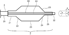
- the side view of the balloon catheter which concerns on one Embodiment of this invention is shown.
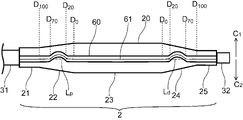
- the cross-sectional view in the longitudinal axis direction in the expanded state of the balloon of the balloon catheter shown in FIG. 1 is shown.
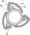
- a cross-sectional view taken along the line III-III of FIG. 1 is shown. It shows the cross-sectional view in the radial direction in the contracted state of the straight tube part of the balloon shown in FIG.
- FIG. 2 shows a cross-sectional view in the radial direction in a contracted state of the tapered portion of the balloon shown in FIG. It shows the plan view seen from the protrusion side in the contracted state of the balloon shown in FIG. It represents the plan view seen from the protrusion side in the contracted state of the balloon which concerns on another embodiment of this invention.
- FIG. 14 shows a cross-sectional view taken along the line XV-XV.
- FIG. 14 shows a cross-sectional view taken along the line XVI-XVI.
- FIG. 14 shows a cross-sectional view taken along the line XVII-XVII of FIG. It represents the plan view seen from the protrusion side in the contracted state of the balloon which concerns on another embodiment of this invention. It shows the plan view seen from the protrusion side in the contracted state of the balloon which concerns on still another Embodiment of this invention.
- FIG. 2 shows a partial side view of the balloon shown in FIG. 2 in a contracted state. It shows the plan view seen from the protrusion side of the balloon shown in FIG.
- the perspective view of the parison before expansion which concerns on one Embodiment of this invention is shown. It represents the sectional view perpendicular to the longitudinal axis direction of the 1st cylinder or the 2nd cylinder in the manufacturing method which concerns on one Embodiment of this invention.
- the diameter in the step of arranging the distal side tapered portion in the first tubular object or the step of arranging the proximal side tapered portion in the second tubular object. Represents a cross-sectional view of the direction.
- FIG. 24 shows a radial cross-sectional view of the first cylindrical object or the second tubular object shown in FIG. 24 at another location in the longitudinal axis direction.
- FIG. 24 shows a radial cross-sectional view of the first cylindrical object or the second tubular object shown in FIG. 24 at a further location in the longitudinal axis direction.
- a radial cross-sectional view of a third tubular object in the manufacturing method according to the embodiment of the present invention is shown.
- the balloon for a balloon catheter has a balloon body having an outer surface and an inner surface, and the balloon body is located at a straight tube portion and a distance distal to the straight tube portion. It has a position-side taper portion and a proximal-side taper portion located proximal to the straight pipe portion, and the distal-side taper portion, the straight-tube portion, and the proximal-side taper portion are balloons. It has a protruding portion that protrudes radially outward from the outer surface of the main body and extends in the longitudinal axis direction of the balloon body, and the protruding portion has a tip portion in the radial cross section of the balloon body.
- the tip of the protruding portion of the distal tapered portion is the tip of the proximal end of the distal tapered portion and the tip of the distal end of the distal tapered portion. It is arranged on the first direction side in the circumferential direction of the balloon body with respect to the straight line L d connecting the balloon body, and is not arranged on the second direction side, or is arranged on the second direction side and is arranged in the first direction. Not arranged on the side.
- the tip of the protruding portion of the proximal tapered portion is the tip of the distal end of the proximal tapered portion and the tip of the proximal end of the proximal tapered portion. It is arranged on the first direction side in the circumferential direction of the balloon body with respect to the straight line L p connecting the balloon body, and is not arranged on the second direction side, or is arranged on the second direction side and is arranged in the first direction. Not arranged on the side.
- the tip of at least one of the distal tapered portion and the proximal tapered portion is arranged on the first direction side or the second direction side in the circumferential direction of the balloon body. Therefore, during delivery of the balloon or when the balloon is delivered to the lesion, the stenosis may be incised diagonally or a wide area may be incised in one motion while advancing or retracting the balloon in the contracted state. Can be done.
- a balloon for a balloon catheter may be simply referred to as a "balloon".
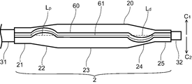
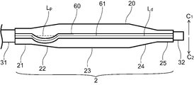
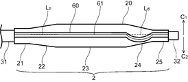
- FIG. 1 shows a side view of a balloon catheter according to an embodiment of the present invention
- FIG. 2 shows a sectional view of the balloon catheter shown in FIG. 1 in an expanded state in the longitudinal axis direction
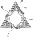
- FIG. 3 shows a cross-sectional view of FIG. Represents a cross-sectional view of III-III
- FIG. 4 shows a radial cross-sectional view of the straight tube portion of the balloon shown in FIG. 2 in a contracted state
- FIG. 5 shows a radial cross-sectional view of the tapered portion of the balloon shown in FIG. 2 in a contracted state.
- FIG. 1 shows a side view of a balloon catheter according to an embodiment of the present invention
- FIG. 2 shows a sectional view of the balloon catheter shown in FIG. 1 in an expanded state in the longitudinal axis direction
- FIG. 3 shows a cross-sectional view of FIG. Represents a cross-sectional view of III-III
- FIG. 4 shows a radial cross-sectional view of the straight
- FIG. 6 shows a plan view seen from the protruding portion side in the contracted state of the balloon shown in FIG. 2
- FIGS. 7 to 13 show a plan view seen from the protruding portion side in the contracted state of the balloon according to different embodiments.
- show. 14 shows a side view of the balloon shown in FIG. 2 in a folded state
- FIGS. 15, 16, and 17 show an XV-XV cross-sectional view, an XVI-XVI cross-sectional view, and a cross-sectional view of the balloon shown in FIG. 14, respectively.
- 18 and 19 represent a plan view of the balloon according to another embodiment as viewed from the protruding portion side in the contracted state.
- FIG. 14 shows a side view of the balloon shown in FIG. 2 in a folded state
- FIGS. 15, 16, and 17 show an XV-XV cross-sectional view, an XVI-XVI cross-sectional view,
- FIG. 20 shows a partial side view of the balloon shown in FIG. 2 in a contracted state, that is, a side view of a portion where one protrusion is formed along the balloon body.
- FIG. 21 shows a plan view of the balloon shown in FIG. 2 as viewed from the protruding portion side.
- the proximal side refers to the direction of the user or the operator's hand with respect to the extending direction of the balloon catheter 1 or the longitudinal axis direction x of the shaft 3, and is opposite to the distal side. It refers to the direction, that is, the direction on the side of the person to be treated. Even if it is not a long member such as the shaft 3, it has the same longitudinal axis direction x as the shaft 3.
- the radial direction y is a direction perpendicular to the longitudinal axis direction x and a direction connecting the center of the balloon body 20 and a point on the circumscribed circle of the balloon body 20 in a cross section perpendicular to the longitudinal axis direction x.
- the circumferential direction z is a direction along the circumference of the circumscribed circle of the balloon body 20 in the expanded state in the cross section perpendicular to the longitudinal axis direction x.
- the balloon catheter 1 has a shaft 3 and a balloon 2 provided on the outside of the shaft 3.
- the balloon catheter 1 has a distal side and a proximal side, and the balloon 2 is provided on the distal side of the shaft 3.
- the balloon catheter 1 is configured so that fluid is supplied to the inside of the balloon 2 through the shaft 3, and the expansion and contraction of the balloon 2 can be controlled by using an indeflator (balloon pressurizer).
- the fluid may be a pressurized fluid pressurized by a pump or the like.
- the shaft 3 has a fluid flow path inside and further has a guide wire insertion passage.
- the shaft 3 has an outer tube 31 and an inner tube 32, and the inner tube 32 inserts a guide wire. It may be configured to function as a passage and the space between the inner tube 32 and the outer tube 31 to function as a fluid flow path.
- the inner tube 32 extends from the distal end of the outer tube 31 and penetrates distally to the balloon 2 to form a balloon. It is preferred that the distal side of 2 is joined to the inner tube 32 and the proximal side of the balloon 2 is joined to the outer tube 31.
- the balloon 2 for the balloon catheter 1 has a balloon body 20 having an outer surface and an inner surface, and the balloon body 20 is farther from the straight tube portion 23 and the straight tube portion 23. It has a distal tapered portion 24 located on the position side and a proximal tapered portion 22 located proximal to the straight tube portion 23, and has a distal tapered portion 24.
- the straight pipe portion 23 and the proximal tapered portion 22 have a protruding portion 60 that protrudes radially outward from the outer surface of the balloon body 20 and extends in the longitudinal axis direction x of the balloon body 20.
- the protrusion 60 has a tip portion 61 in the radial cross section of the balloon body 20, and satisfies at least one of the following (1) and (2).
- the tip portion 61 of the protruding portion 60 of the distal side tapered portion 24 is the tip portion 61 of the proximal end of the distal side tapered portion 24 and the distal side tapered portion. It is arranged on the first direction C 1 side of the circumferential direction z of the balloon body 20 and not on the second direction C 2 side with respect to the straight line L d connecting the tip portion 61 of the distal end of 24. Or, it is arranged on the second direction C 2 side and not on the first direction C 1 side.
- the tip portion 61 of the protruding portion 60 of the proximal side tapered portion 22 is the tip portion 61 of the distal end of the proximal side tapered portion 22 and the proximal side tapered portion. It is arranged on the first direction C 1 side of the circumferential direction z of the balloon body 20 and not on the second direction C 2 side with respect to the straight line L p connecting the tip portion 61 of the proximal end of 22. Or, it is arranged on the second direction C 2 side and not on the first direction C 1 side.
- the tip portion 61 of the protruding portion 60 of at least one of the distal side tapered portion 24 and the proximal side tapered portion 22 is on the first direction C 1 side or the second in the circumferential direction z of the balloon body 20. Since it is arranged on the side of direction C 2 , when the balloon 2 is delivered or when the balloon 2 is delivered to the lesion, the stenosis is cut diagonally or once while the balloon 2 is advanced or retracted in the contracted state. A wide range of areas can be incised by movement.
- the balloon 2 is located distal to the distal tapered portion 24 and proximal to the proximal tapered portion 22, respectively, the non-expanding distal sleeve portion 25 and the proximal side. It may have a sleeve portion 21. At least a part of the distal sleeve portion 25 and the proximal sleeve portion 21 can be fixed to the shaft 3, and if the shaft 3 has an outer tube 31 and an inner tube 32, it is proximal. At least a part of the side sleeve portion 21 may be fixed to the outer tube 31, and at least a part of the distal side sleeve portion 25 may be fixed to the inner tube 32.
- the distal tapered portion 24 and the proximal tapered portion 22 are formed so as to reduce their diameters as they move away from the straight pipe portion 23. Since the balloon body 20 has a straight tube portion 23 having the maximum diameter in the expanded state, when the balloon 2 is expanded in the narrowed portion, the straight tube portion 23 sufficiently contacts the narrowed portion and the narrowed portion is formed. It can be easily expanded or incised. Further, as will be described later, when the balloon 2 is contracted, the blade 29 is formed, but the distal tapered portion 24 and the proximal tapered portion 22 whose outer diameter becomes smaller as the balloon main body 20 moves away from the straight tube portion 23.
- the protruding portion 60 is exposed from the blade 29 of the balloon 2 in the distal side tapered portion 24 and the proximal side tapered portion 22.
- the exposed protrusion 60 allows the stenosis to be incised even when the balloon 2 is contracted.
- the protruding portion 60 of the balloon 2 is a portion that protrudes outward in the radial direction from the outer surface of the balloon body 20 in the expanded state of the balloon 2.
- the maximum length of the protruding portion 60 protruding outward in the radial direction from the outer surface of the balloon body 20 is preferably 1.2 times or more the film thickness of the balloon body 20. It is more preferably 1.5 times or more, still more preferably 2 times or more, and 100 times or less, 50 times or less, 30 times or less, or 10 times or less is also allowed.
- the protruding portion 60 makes it easier to make a notch at an appropriate depth in the narrowed portion, and the incision becomes easier. Further, such a protruding portion 60 makes it possible to improve the strength of the balloon 2 and suppress the over-expansion of the balloon 2 at the time of pressurization.
- the number of protrusions 60 in the circumferential direction z of the balloon 2 may be one or may be plural as shown in FIG.
- the balloon 2 has a plurality of protrusions 60 in the circumferential direction z
- the separation distance is preferably longer than the maximum peripheral length of the protrusion 60.
- the protruding portion 60 has a tip portion 61 in the radial cross section of the balloon body 20. Since the tip portion 61 makes it easier to make an incision in the stenosis portion, the stenosis portion can be incised while preventing dissociation of the intima of the blood vessel.
- the tip portion 61 is a portion in which the protruding portion 60 protrudes most outward in the radial direction from the outer surface of the balloon body 20, and may have a shape having an acute angle as shown in FIG. , It may have a shape having an acute angle, a shape consisting of a curved line, or a flat shape.
- the shape of the protrusion 60 in the radial cross section may be arbitrary, may be a substantially triangular shape as shown in FIG. 3, and may be polygonal, fan-shaped, wedge-shaped, convex-shaped, spindle-shaped, or the like. You may.
- the contracted state of the balloon 2 is a state after the fluid is discharged from the inside of the balloon 2 or before the fluid is applied to the inside of the balloon 2, and in the contracted state of the balloon 2, the balloon is in a contracted state.
- a portion where the inner surface of the main body 20 is close to the shaft 3 and a blade 29 are formed.
- the balloon 2 in the expanded state has a blade forming portion 28 that forms the blade 29 in the contracted state.
- the shaft 3 has an outer tube 31 and an inner tube 32
- the balloon 2 has a portion where the inner surface of the balloon body 20 is close to the inner tube 32 in a contracted state.
- FIG. 4 showing a sectional view of the straight pipe portion 23 in the contracted state in the radial direction y
- FIG. 5 showing a sectional view of the tapered portion (distal side tapered portion 24 or proximal side tapered portion 22) showing the radial direction y.
- the straight pipe portion 23 is the portion of the balloon 2 having the maximum diameter in the expanded state and the tapered portion is the diameter-reduced portion, the blade 29 of the straight pipe portion 23 in the radial cross section.
- the length y in the radial direction is longer than the length y in the radial direction of the blade 29 of the tapered portion.
- the length y in the radial direction of the vane 29 in the cross section in the radial direction y is also taken. It gradually shortens toward the distal side and the proximal side, and the blade 29 may not be formed in the distal side portion of the distal side taper portion 24 and the proximal side portion of the proximal side taper portion 22. It is preferable that the blade 29 is not formed at the distal end portion of the distal taper portion 24 and the proximal end portion of the proximal taper portion 22.
- the protrusion 60 is not obstructed by the wing 29 in the cavity wall. It is possible to make contact and make an incision in the narrowed portion.
- the tip portion 61 of at least one of the distal side tapered portion 24 and the proximal side tapered portion 22 has a straight line L d and a straight line L, respectively. Independently of p , they are arranged on the first direction C 1 side of the circumferential direction z of the balloon body 20 and not on the second direction C 2 side, or on the second direction C 2 side. It is arranged and not arranged on the first direction C 1 side. That is, the tip portion 61 of the protruding portion 60 of at least one of the distal side tapered portion 24 and the proximal side tapered portion 22 is not arranged on both sides across the straight line L d and the straight line L p .
- the tip portion 61 of the protrusion 60 of the entire section extending from the distal end to the proximal end in at least one of the distal side tapered portion 24 and the proximal side tapered portion 22 is the first direction C 1 .
- the tip portion 61 of the protruding portion 60 of at least one of the distal side tapered portion 24 and the proximal side tapered portion 22 is on the first direction C 1 side.
- it may have at least a part arranged on the second direction C 2 side, and the other part may be arranged on the straight line L d or the straight line L p .
- the tip portions 61 of the protrusions 60 of both the distal taper portion 24 and the proximal taper portion 22 are both in the first direction C 1 with respect to the straight line L d and the straight line L p . It may be arranged on the side or the second direction C 2 side. With such a configuration, the tip portion 61 of the protruding portion 60 in the distal side tapered portion 24 and the proximal side tapered portion 22 can be arranged on the same side in the circumferential direction z, so that the balloon 2 can be placed in the body cavity.
- the tip portion 61 for advancing and retracting can be arranged on the same side in the circumferential direction z, and both the distal side tapered portion 24 and the tip portion 61 of the protruding portion 60 in the proximal side tapered portion 22 are used. It is possible to make an oblique incision on the same side of the body cavity wall in the circumferential direction z, or to make an incision in a wide area with one operation.
- the tip portion 61 of the protruding portion 60 of the distal side tapered portion 24 is arranged on the first direction C 1 side or the second direction C 2 side with respect to the straight line L d . Even if the tip portion 61 of the protruding portion 60 of the proximal side tapered portion 22 is arranged on the second direction C 2 side or the first direction C 1 side opposite to the distal side tapered portion 24 with respect to the straight line L p . good.
- the tip 61 of the protrusion 60 in the distal tapered portion 24 and the proximal tapered portion 22 can be arranged on different sides in the circumferential direction z, so that the balloon 2 can be placed in the body cavity.
- the tip 61 for advancing and retreating within can be arranged on different sides in the circumferential direction z, and different points can be incised diagonally for advancing and retreating the balloon 2 and wider in one operation.
- the area can be incised.
- the tip portion 61 of the protruding portion 60 of the proximal side tapered portion 22 is arranged on the first direction C 1 side or the second direction C 2 side with respect to the straight line L p .
- the tip portion 61 of the protruding portion 60 of the distal side tapered portion 24 may not be arranged on either the first direction C 1 side or the second direction C 2 side with respect to the straight line L d . With such a configuration, only the tip portion 61 of the protruding portion 60 of the proximal side tapered portion 22 can be arranged on the first direction C 1 side or the second direction C 2 side in the circumferential direction z, and is distal.
- the tip portion 61 of the protrusion 60 of the side taper portion 24 is not curved in the circumferential direction z, the tip portion 61 of the distal side taper portion 24 makes a straight incision while retracting the balloon 2, for example, on the proximal side.
- the tip portion 61 of the tapered portion 22 can be used to make an oblique incision or to make a wide area incision with a single operation.
- the tip portion 61 of the protruding portion 60 of the distal side tapered portion 24 is arranged on the first direction C 1 side or the second direction C 2 side with respect to the straight line L d .
- the tip portion 61 of the protruding portion 60 of the proximal side tapered portion 22 may not be arranged on either the first direction C 1 side or the second direction C 2 side with respect to the straight line L p . With such a configuration, only the tip portion 61 of the protruding portion 60 of the distal side tapered portion 24 can be arranged on the first direction C 1 side or the second direction C 2 side in the circumferential direction z, and is proximal.
- the tip portion 61 of the protrusion 60 of the side taper portion 22 is not curved in the circumferential direction z, the tip portion 61 of the proximal side taper portion 22 makes a straight incision, for example, while advancing the balloon 2 on the distal side.
- the tip portion 61 of the tapered portion 24 can be used to make an oblique incision or to make a wide area incision with a single operation.
- the balloon 2 most suitable for the treatment of the lesion at the treatment target site can be obtained.
- 6 to 13 show a mode in which the straight line L d and the straight line L p extend in the longitudinal axis direction x, but the straight line L d and the straight line L p are in the circumferential direction z with respect to the longitudinal axis direction x. It may be extended to have an angle.
- FIGS. 6 to 13 show an embodiment in which the distal sleeve portion 25 and the proximal sleeve portion 21 also have the protruding portion 60, but the distal sleeve portion 25 and the proximal sleeve portion are also shown.
- 21 does not have to have a protrusion 60, and the distal sleeve portion 25 and the proximal sleeve portion 21 project inwardly in the radial direction from the inner surface of the balloon body 20. It may have a part. If the distal sleeve portion 25 and the proximal sleeve portion 21 do not have the protrusion 60, the balloon 2 can be easily inserted into the body cavity and advanced or retracted in the body cavity.
- the length of the protrusion 60 in the distal taper portion 24 or the proximal taper portion 22 is larger than that of the protrusion 60 in the straight pipe portion 23. It is preferably shorter than the length. Further, in the expanded state, it is preferable that the tip portion 61 of the protruding portion 60 in the distal side tapered portion 24 and the proximal side tapered portion 22 is not arranged outward with respect to the straight lines L d and L p .
- the balloon 2 is folded in the contracted state of the balloon 2.
- the blade 29 formed by the contraction of the balloon 2 shown in FIGS. 4 and 5 is wound around the shaft 3. Since the length y of the blade 29 in the radial direction is long in the straight pipe portion 23 having the maximum diameter, the amount of winding of the blade 29 increases as shown in FIG.
- the length y in the radial direction of the blade 29 becomes shorter due to the reduced diameter, and in one embodiment of the present invention, the length becomes longer. It becomes shorter toward the distal side and the more proximal side.
- the blade 29 shorter than that in the straight pipe portion 23 is the shaft 3.
- a shorter blade 29 wraps around the shaft 3 (inner tube 32) as shown in FIG. 17 in the more distal and more proximal portions.
- the diameter of the balloon 2 and the number of blades 29 the amount of wrapping of the blades 29 is shown in FIG. 17 even in the portion of the distal taper portion 24 and the proximal taper portion 22 near the straight pipe portion 23. As shown, it can be reduced, and further, the blades 29 can be hardly formed.
- the balloon 2 can be easily inserted into the body cavity.
- the end of the distal tapered portion 24 and the proximal tapered portion 22 on the longitudinal axis direction x of the balloon body 20 on the straight tube portion 23 side is positioned at 0%.
- 0 and the other end are set to the position D 100 of 100%, it is preferable to satisfy at least one of the following (1) and (2).
- the tip 61 of the protrusion 60 in the entire section from the 20% position D 20 to the 70% position D 70 of the distal taper portion 24 is on the first direction C 1 side or the first direction with respect to the straight line L d .
- the tip 61 of the protrusion 60 in the section from 90% position D 90 to 100% position D 100 of the distal taper portion 24 is the first with respect to the straight line L d . It is not arranged on the 1st direction C 1 side and the 2nd direction C 2 side.
- the tip portion 61 of the protruding portion 60 in the entire section from the 20% position D 20 to the 70% position D 70 of the proximal side tapered portion 22 is the first direction C 1 side or the first with respect to the straight line L p .
- the tip portion 61 of the protrusion 60 in the section from 90% position D 90 to 100% position D 100 of the proximal side taper portion 22 is the first with respect to the straight line L p . It is not arranged on the 1st direction C 1 side and the 2nd direction C 2 side.
- the section from 90% position D 90 to 100% position D 100 which is the farthest from the straight tube portion 23 of the distal taper portion 24 and the proximal taper portion 22, advances or retracts the balloon 2 in the body cavity.
- the tip portion 61 of at least one of the distal side tapered portion 24 and the proximal side tapered portion 22 in the contracted state of the balloon 2 is a straight line Ld.
- FIG. 18 shows an embodiment in which both the above conditions (1) and (2) are satisfied, but either the distal side tapered portion 24 or the proximal side tapered portion 22 has the above (1) or It may be an embodiment satisfying the condition of (2). From the viewpoint of making a straight cut on both tip sides of the balloon 2, it is preferable that both the distal tapered portion 24 and the proximal tapered portion 22 satisfy the above conditions (1) and (2). .. As a result, it is possible to make a straight cut on the tip side of the balloon 2 regardless of whether the balloon 2 is advanced or retracted.
- the balloon 2 according to the embodiment of the present invention further satisfies at least one of the following (1) and (2) in the above-described embodiment.
- the distance from the straight line Lp of the tip portion 61 of the protruding portion 60 at the position D 40 of 40% of the proximal side tapered portion 22 is the protruding portion 60 at the position D 60 of 60% of the proximal side tapered portion 22. It is 1.2 times or more the distance from the straight line Lp of the tip portion 61 of the above.
- the distance of the tip 61 of the protrusion 60 at the 40% position D 40 from the straight line L d or the straight line L p is from the straight line L d or the straight line L p of the tip 61 of the protrusion 60 at the 60% position D 60 .
- the distance is preferably 1.5 times or more, more preferably 2 times or more.
- the distance from the straight line L d or the straight line L p of the tip portion 61 of the protrusion 60 at the position D 40 at 40% is the straight line L d or the straight line L of the tip portion 61 of the protrusion 60 at the position D 60 at 60%.
- the distance from p is preferably 10 times or less, more preferably 8 times or less, still more preferably 5 times or less.
- a more curved portion can be formed in the entire section from the 20% position D 20 to the 70% position D 70 arranged on the second direction C 2 side, while moving the balloon 2 forward or backward. It is possible to make a more diagonal incision or to make a larger area with a single operation.
- the tip 61 of the protrusion 60 in the entire section from the 20% position D 20 to the 70% position D 70 of the distal tapered portion 24 has a straight line L d around the central axis 20C of the balloon body 20. It is arranged inward or at the same position in the radial direction y of the balloon body 20 with respect to the virtual curved surface C d obtained by rotating the balloon body 20 to.
- the tip portion 61 of the protrusion 60 in the entire section from the 20% position D 20 to the 70% position D 70 of the proximal side tapered portion 22 has a straight line L p around the central axis 20C of the balloon body 20.
- the tip portion 61 of at least one of the protruding portions 60 of the distal tapered portion 24 and the proximal tapered portion 22 has a diameter of the balloon body 20 with respect to the virtual curved surface C d or the virtual curved surface C p . Since it is arranged inward in the direction y or at the same position, the diameter of the portion can be suppressed, and the balloon 2 can be easily inserted when moving forward or backward in the body cavity.
- the straight line L d or the straight line L p may have an angle in the radial direction y with respect to the central axis 20C (that is, the longitudinal axis direction x) of the balloon body 20.
- the virtual curved surface C d and the virtual curved surface C p in the embodiment in which the straight line L d or the straight line L p has an angle in the radial direction y with respect to the central axis 20C of the balloon body 20 are conical bases as shown in FIG. It becomes the side of.
- the protrusion 60 in the straight pipe portion 23 When the diameter of the balloon 2 is large, or when the diameter of the protrusion 60 in the distal taper portion 24 and the proximal taper portion 22 in the radial cross section is larger than the length in the radial direction y, the protrusion 60 in the straight pipe portion 23.
- the straight line L d or the straight line L p has an angle in the radial direction y with respect to the central axis 20C of the balloon body 20, and the virtual curved line C d and the virtual curved line C p is the side surface of the conical stand whose bottom surface is on the straight pipe portion 23 side.
- the diameters of the distal and proximal portions of the distal tapered portion 24 and the proximal tapered portion 22 can be kept small during contraction, and the balloon 2 is inserted into the body cavity. Since the diameter of the portion on the tip side when moving forward or backward is reduced, the balloon 2 can be easily inserted into the body cavity.
- the straight line L d or the straight line L p may be parallel to the central axis 20C (that is, the longitudinal axis direction x) of the balloon body 20.
- the virtual curved surface C d and the virtual curved surface C p in the embodiment in which the straight line L d or the straight line L p is parallel to the central axis 20C of the balloon body 20 are the side surfaces of the cylinder. If the straight line L d and the straight line L p are parallel to the central axis 20C of the balloon body 20, the diameter of the straight pipe portion 23 can be suppressed when the balloon 2 contracts, and the blade 29 formed by the contraction of the balloon 2 is a shaft. Since the diameter of the straight tube portion 23 can be suppressed even when the straight tube portion 23 is wound around the body 3, it becomes easy to insert the straight tube portion 23 into the body cavity.
- the virtual curved surface C d and the virtual curved surface C p in the distal tapered portion 24 and the proximal tapered portion 22 both form the side surface of the conical table, but the virtual curved surface in the distal tapered portion 24 is shown.
- C d is the side surface of the cylinder
- the virtual curved surface C p in the proximal tapered portion 22 may be the side surface of the conical base, or vice versa.
- FIG. 20 shows an embodiment in which the above conditions (1) and (2) are satisfied in the entire section from the 20% position D 20 to the 70% position D 70 of both tapered portions.
- the balloon 2 according to the embodiment includes an embodiment in which either the distal tapered portion 24 or the proximal tapered portion 22 satisfies the above condition (1) or (2).
- the tip portion 61 of the protruding portion 60 is arranged inward or at the same position in the radial direction y of the balloon body 20 with respect to the virtual curved surface Cd.
- the tip portion 61 of the protruding portion 60 of at least one of the distal side tapered portion 24 and the proximal side tapered portion 22 is each.
- the balloon body 20 is independently curved toward the first direction C 1 side or the second direction C 2 side of the circumferential direction z with respect to the straight line L d and the straight line L p , respectively, but in the expanded state, it is arranged. As shown in FIG.
- the balloon body 20 is arranged at the same position in the circumferential direction z.
- the balloon can be incised straight when the balloon 2 is expanded at the lesion or the like after delivery, but in the contracted state, the stenosis can be incised diagonally while advancing or retreating, or a wide area can be opened with one operation. It can be a balloon that can be incised.
- the protruding portion 60 of the distal tapered portion 24, the protruding portion 60 of the straight pipe portion 23, and the protruding portion 60 of the proximal tapered portion 22 are continuous in the longitudinal axis direction x of the balloon body 20. It is preferable that it is extended. Since the protruding portion 60 extends continuously in the longitudinal axis direction x of the balloon body 20, the strength of the balloon 2 can be further improved and the overexpansion of the balloon 2 during pressurization can be further suppressed. It will be possible.
- the balloon body 20 has a blade forming portion 28 that forms a blade 29 in a contracted state, and the protruding portion 60 is arranged in addition to the blade forming portion 28. It is preferable that it is. If the protrusion 60 is arranged other than the blade forming portion 28, the protrusion 60 does not hinder the folding of the blade 29, so that the balloon 2 can be easily folded, and the outer diameter of the balloon 2 in the folded state can be easily folded. Can be suppressed. In a more preferred embodiment, as shown in FIGS. 4 and 5, a plurality of blades 29 are formed in a contracted state, and the protrusions 60 are preferably arranged between the plurality of blades 29.
- the protrusion 60 can be protected by the blades 29 as shown in FIGS. 15 and 16 when the balloon 2 is folded, and when the balloon 2 is folded and inserted into the body cavity, the protrusion 60 can be protected. It is possible to suppress damage and prevent the protrusion 60 from acting on the body cavity wall at an unintended location. Further, by adjusting the length y in the radial direction of the blade 29 by adjusting the diameter of the balloon 2 and the number of blades 29, the distal tapered portion 24 and the proximal portion as shown in FIGS. 16 and 17. The range in which the blade 29 covers the protruding portion 60 in the side tapered portion 22 can be adjusted.
- the distal taper portion is tapered.
- the protrusion 60 can be exposed from the blade 29 in most of the portion 24 and the proximal tapered portion 22, and the exposed protrusion 60 allows the balloon 2 to be incised while advancing or retracting.
- the blade 29 can be long enough to cover the protrusion 60 beyond the 50% position of the distal taper 24 and the proximal taper 22, in this case exposed from the blade 29 of the protrusion 60.
- the portion to be moved can be made small, the action of the protruding portion 60 when moving the balloon 2 forward or backward can be suppressed.
- the range in which the blade 29 covers the protruding portion 60 in this way it becomes possible to cope with application to various lesions.
- FIGS. 15 to 17 show an embodiment of three blades 29, but the number of blades 29 is not particularly limited as long as the balloon 2 can be folded, and for example, two or more blades are preferable. More preferably, it may be 4 or more, or 5 or more.
- the diameter of the balloon 2 can be reduced while covering the protrusion 60 at the time of folding to improve the insertion into the body cavity.
- the number of blades 29 is preferably 10 or less, more preferably 8 or less, still more preferably 6 or less. If the upper limit of the number of blades 29 is within the above range, even a balloon 2 having a large diameter can be easily folded.
- the range of the number of blades 29 By setting the range of the number of blades 29 to the above range, the size of the portion of the distal side tapered portion 24 and the proximal side tapered portion 22 covered by the blade 29 of the protruding portion 60 can be adjusted.
- Examples of the material constituting the balloon body 20 include a polyolefin resin such as polyethylene, polypropylene and an ethylene-propylene copolymer, a polyester resin such as polyethylene terephthalate and a polyester elastomer, a polyurethane resin such as polyurethane and a polyurethane elastomer, and polyphenylene.
- a polyolefin resin such as polyethylene, polypropylene and an ethylene-propylene copolymer
- a polyester resin such as polyethylene terephthalate and a polyester elastomer
- a polyurethane resin such as polyurethane and a polyurethane elastomer
- polyphenylene examples include polyamide resins such as sulphide resins, polyamides and polyamide elastomers, fluororesins, silicone resins, and natural rubbers such as latex rubbers. Only one of these may be used, or two or more thereof may be used in combination.
- polyamide-based resins polyester-based resins, and polyurethane-based resins are preferably used.
- an elastomer resin from the viewpoint of thinning the balloon body 20 and flexibility.
- nylon 12 nylon 12 is more preferable because it can be molded relatively easily during blow molding. be.
- polyamide elastomers such as polyether ester amide elastomers and polyamide ether elastomers are preferably used.
- the polyether ester amide elastomer is preferably used because of its high yield strength and good dimensional stability of the balloon body 20.
- the protrusion 60 is preferably made of the same material as the balloon body 20. If the protrusion 60 is made of the same material as the balloon body 20, the protrusion 60 can make it difficult for the balloon body 20 to damage the outer surface while maintaining the flexibility of the balloon 2. It is preferable that the balloon body 20 and the projecting portion 60 are integrally molded. This makes it possible to prevent the protruding portion 60 from falling off from the balloon body 20.
- the material constituting the shaft 3 examples include polyamide-based resin, polyester-based resin, polyurethane-based resin, polyolefin-based resin, fluorine-based resin, vinyl chloride-based resin, silicone-based resin, and natural rubber. Only one of these may be used, or two or more thereof may be used in combination. Above all, the material constituting the shaft 3 is preferably at least one of a polyamide-based resin, a polyolefin-based resin, and a fluorine-based resin. As a result, the slipperiness of the surface of the shaft 3 can be enhanced, and the insertability of the balloon catheter 1 in the body cavity can be improved.
- the joining between the balloon 2 and the shaft 3 includes adhesion by an adhesive, welding, and caulking by attaching a ring-shaped member to a place where the end of the balloon 2 and the shaft 3 overlap. Above all, it is preferable that the balloon 2 and the shaft 3 are joined by welding. Since the balloon 2 and the shaft 3 are welded together, it is difficult to release the joint between the balloon 2 and the shaft 3 even if the balloon 2 is repeatedly expanded and contracted, and the joint strength between the balloon 2 and the shaft 3 can be easily increased. Can be done.
- a hub 4 may be provided on the proximal side of the shaft 3, and the hub 4 has a flow path of a fluid supplied to the inside of the balloon 2 and a pain.
- the fluid injection unit 7 may be provided.
- the hub 4 has a guide wire insertion portion 5 that communicates with the insertion passage of the guide wire. Since the balloon catheter 1 has a hub 4 provided with a fluid injection portion 7 and a guide wire insertion portion 5, an operation of supplying fluid to the inside of the balloon 2 to expand and contract the balloon 2 and along the guide wire can be performed.
- the balloon catheter 1 can be easily delivered to the treatment site. As shown in FIG.
- the joining between the shaft 3 and the hub 4 examples include adhesion with an adhesive, welding, and the like. Above all, it is preferable that the shaft 3 and the hub 4 are joined by adhesion.
- the shaft 3 and the hub 4 are made of a highly flexible material
- the hub 4 is made of a highly rigid material, and so on. When the material constituting the 4 is different, the joint strength between the shaft 3 and the hub 4 can be increased to increase the durability of the balloon catheter 1.
- the present invention also provides a method for manufacturing a balloon 2 for a balloon catheter 1 according to an embodiment of the present invention.
- the method for manufacturing the balloon 2 according to the embodiment of the present invention will be described with reference to FIGS. 22 to 27.
- FIG. 22 shows a perspective view of a parison before expansion according to an embodiment of the present invention, showing a state of having a lumen and a thick portion.
- FIG. 23 shows a radial cross-sectional view of the first tubular object or the second tubular object in the manufacturing method according to the embodiment of the present invention.
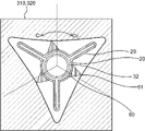
- FIG. 24 shows the step of arranging the distal tapered portion in the first tubular object or the proximal tapered portion in the second tubular object in the manufacturing method according to the embodiment of the present invention.
- FIG. 25 shows a radial cross-sectional view of the first tubular object or the second tubular object shown in FIG. 24 at another location in the longitudinal direction, in which the tip of the protruding portion of the distal taper portion is formed.
- the part where the portion arranged on the first direction side in the circumferential direction of the balloon body is arranged with respect to the straight line L d , or the tip of the protruding portion of the proximal side tapered portion is the tip of the balloon body with respect to the straight line L p .
- a radial cross-sectional view of a portion where a portion arranged on the first direction side in the circumferential direction is arranged is shown.
- FIG. 26 shows a radial cross-sectional view of the first tubular object or the second tubular object shown in FIG. 24 at yet another portion in the longitudinal direction, and is the tip end portion of the protrusion of the distal taper portion.
- FIG. 27 shows a radial cross-sectional view of a third tubular object in the manufacturing method according to the embodiment of the present invention.
- the first tubular object 310, the second tubular object 320, and the third tubular object each have a space portion extending in the longitudinal axis direction inside.
- a balloon for a balloon catheter having a step of preparing 330 and a balloon body 20 having an outer surface and an inner surface, the balloon body 20 is located on the straight tube portion 23 and distal to the straight tube portion 23. It has a distal tapered portion 24 and a proximal tapered portion 22 located proximal to the straight tube portion 23, with the distal tapered portion 24 and the straight tube portion 23.
- the proximal side tapered portion 22 protrudes outward in the radial direction from the outer surface of the balloon main body 20, and has a protruding portion 60 extending in the longitudinal axis direction x of the balloon main body 20.
- the distal tapered portion 24 is arranged in the first tubular object 310, and the proximal tapered portion 22 is arranged in the second tubular object 320. It has an arrangement step of arranging the straight pipe portion 23 in the third tubular object 330, and satisfies at least one of the following (1) and (2).
- the tip portion 61 of the protruding portion 60 of the distal side tapered portion 24 is arranged so as to be curved toward the first direction C 1 side or the second direction C 2 side of the circumferential direction z of the balloon body 20 in the contracted state. Can be done. Further, by arranging so that at least a part of the protruding portion 60 of the proximal side tapered portion 22 abuts on the inner surface of the second tubular object 320, the protruding portion 60 is moved in the circumferential direction z of the balloon body 20. Can be done.
- the tip portion 61 of the protruding portion 60 of the proximal side tapered portion 22 is arranged so as to be curved toward the first direction C 1 side or the second direction C 2 side of the circumferential direction z of the balloon body 20 in the contracted state. Can be done.
- the step (1) above may be performed, and the proximal side tapered portion 22
- the step (2) above may be carried out, and the distal side tapered portion 24 and the proximal side tapered portion 24 may be carried out.
- both steps (1) and (2) may be carried out.
- a tubular parison 200 made of a resin as shown in FIG. 22 is placed in a mold having a groove in the lumen, and the balloon is prepared by biaxial stretching blow molding. can do.
- the protrusion 60 inserts the parison 200 into the lumen of the mold, inserts the thick portion 220 of the parison 200 into the groove of the mold, and introduces a fluid into the lumen 210 of the parison 200 to introduce the parison 200. It can be formed by inflating.
- the thick portion of the parison 200 is formed in a portion where there is no groove in the mold.
- the balloon 2 can be manufactured by pressing the 220 and introducing a fluid into the lumen 210 of the parison 200 to inflate the parison 200.
- the material constituting the parison 200 the description of the material constituting the balloon body 20 can be referred to.
- the first cylindrical object 310 in the case of carrying out the step (1) of the manufacturing method according to the embodiment of the present invention has a space portion extending in the longitudinal axis direction x inside. It is preferable that the shape of the space portion in the radial direction y is different in the longitudinal axis direction x. That is, it is preferable that the shape of the space portion is different depending on the moving distance when the tip portion 61 of the protruding portion 60 of the distal side tapered portion 24 is moved in the circumferential direction z of the balloon body 20 in the contracted state.
- the position where at least a part of the inner surface of the first tubular object 310 and the protrusion 60 of the distal taper portion 24 abuts can be changed, and the tip portion of the protrusion 60 of the distal taper portion 24 can be changed. It is possible to adjust the distance that the balloon body 20 moves in the circumferential direction z while preventing the 61 from moving in the radial direction y of the balloon body 20 in the contracted state.
- the space portion of the tubular object 310 preferably has a space portion having a shape that does not abut on the protruding portion 60, for example, a first cylinder at a position where the proximal end of the distal tapered portion 24 is arranged.
- the space portion of the object 310 may have a shape as shown in FIG. 24.
- the tip portion 61 of the protrusion 60 of the distal taper portion 24 is a straight line Ld.
- the space portion of the first tubular object 310 at the location where the portion arranged on the first direction C 1 side of the circumferential direction z of the balloon body 20 is arranged is the protruding portion 60 as shown in FIG. 25. It is preferable to have a space portion having a shape in which at least a part of the abutment is in contact with the surface.
- the space portion of the above has a space portion having a shape in which at least a part of the protrusion 60 is in contact with the protrusion 60 as shown in FIG. 26. As described above, since the shape of the space portion is changed as shown in FIGS. 24 to 26, the tip portion 61 of the protruding portion 60 of the distal side tapered portion 24 is in a contracted state of the balloon body 20.
- the distance of the balloon body 20 moving in the circumferential direction z can be adjusted while preventing the balloon body 20 from moving in the radial direction y.
- the tip portion 61 of the protruding portion 60 can be moved in the radial direction y of the balloon body 20. While allowing, the inner surface of the first tubular object 310 and at least a part of the protruding portion 60 are brought into contact with each other, and the balloon main body is allowed to move the tip portion 61 of the protruding portion 60 in the radial direction y.
- the shape of the space portion of the first tubular object 310 is not limited to the shapes shown in FIGS. 24 to 26, and the diameter of the balloon body 20 is limited to the shape shown in FIGS. Any shape may be used as long as the distance of the balloon body 20 moving in the circumferential direction z can be adjusted while suppressing or allowing the movement in the direction y.
- the shapes of the first cylindrical object 310 and the second tubular object 320 in the radial cross section are continuously changed in the longitudinal axis direction x.
- the tip portion 61 of the protrusion 60 of the distal side taper portion 24 and the tip portion 61 of the protrusion portion 60 of the proximal side taper portion 22 are continuously inserted in the longitudinal axis direction x in the contracted state of the balloon body 20. It can be moved in the circumferential direction z.
- the third cylindrical object 330 has a space portion extending in the longitudinal axis direction x inside.
- the shape of the space portion of the third tubular object 330 in the radial cross section is the shape of the first tubular object 310 at the position where the proximal end of the distal tapered portion 24 is arranged as shown in FIG. 27.
- the shape may be the same as or different from that of the space portion, but the area of the space portion of the third cylindrical object 330 in the cross section in the radial direction y is the space portion of the first cylindrical object 310. It is preferably larger than the area of.
- the second tubular object 320 has the same configuration as the first tubular object 310. That is, the shape of the space portion in the radial cross section of the second tubular object 320 at the location where the distal end of the proximal side tapered portion 22 is arranged may be the shape shown in FIG. 24. , The second cylindrical object 320 at the place where the tip portion 61 of the protruding portion 60 of the proximal side tapered portion 22 is arranged on the first direction C 1 side in the circumferential direction with respect to the straight line L d . The shape of the space portion may be as shown in FIG.
- the tip portion 61 of the protruding portion 60 of the proximal side tapered portion 22 is further circumferentially oriented in the first direction C 1 with respect to the straight line L d .
- the shape of the space portion of the second tubular object 320 at the place where the portion arranged on the side is arranged may be the shape as shown in FIG. 26. Similar to the first cylindrical object 310, the shape of the space portion in the radial cross section of the second tubular object 320 is not limited to these. In the case of the second tubular object 320 having the above configuration, the position where the inner surface of the second tubular object 320 and at least a part of the protruding portion 60 of the proximal side tapered portion 22 abut can be changed.
- the second cylindrical object 320 has the same configuration as the third tubular object 330. ..
- the protruding portion 60 of the proximal side tapered portion 22 arranged in the space portion of the second tubular object 320 from coming into contact with the inner surface of the second tubular object 320, and the second tubular object is formed.
- the inner surface of the object 320 can be prevented from interfering with the protruding portion 60 of the proximal tapered portion 22.
- the first cylindrical object 310 has the same configuration as the third tubular object 330. ..
- the protruding portion 60 of the distal tapered portion 24 arranged in the space portion of the first tubular object 310 from coming into contact with the inner surface of the first tubular object 310, and the first tubular object is formed.
- the inner surface of the object 310 can be prevented from interfering with the protrusion 60 of the distal tapered portion 24.
- the length of the first tubular object 310 in the longitudinal axis direction x, the length of the second tubular object 320 in the longitudinal axis direction x, and the length of the third tubular object 330 in the longitudinal axis direction x are It should be approximately the same as the length of the distal taper portion 24 in the longitudinal direction x, the length of the proximal taper portion 22 in the longitudinal axis direction x, and the length of the straight pipe portion 23 in the longitudinal axis direction x, respectively. preferable.
- the first tubular object 310, the third tubular object 330, and the second tubular object 320 are longitudinally formed in this order so that the centers of the spatial portions in the radial cross section coincide with each other. It is preferable to insert the balloons 2 into the space portion from the side of the second cylindrical object 320 side by side in the axial direction x. As a result, the distal tapered portion 24 in the first cylindrical object 310, the straight pipe portion 23 in the third tubular object 330, and the proximal tapered portion 22 in the second tubular object 320. Can be placed.
- the arrangement of the tip portion 61 of the protrusion portion 60 in the distal side tapered portion 24 and / or the proximal side taper portion 22 can be habituated. can.
- the balloon 2 can be folded by using a hand, various folding machines, or the like.
- the protrusion 60 is arranged other than the blade forming portion 28, it is preferable that the balloon 2 is folded so that the blade 29 covers the protrusion 60.
- the balloon 2 in which the tip portion 61 of the protruding portion 60 is curved in the circumferential direction z of the balloon body 20 is obtained in the folded state. be able to.
- the materials constituting the first tubular material 310, the second tubular material 320, and the third tubular material 330 are, for example, synthetic resins such as polycarbonate resin, polyacetal resin, and fluororesin, iron, and copper. , Metal such as stainless steel and the like.
- Balloon catheter 2 Balloon 3: Shaft 4: Hub 5: Guide wire insertion part 7: Fluid injection part 20: Balloon body 20C: Central axis of balloon body 21: Proximal side sleeve part 22: Proximal side taper part 23 : Straight tube part 24: Distal taper part 25: Distal sleeve part 28: Blade forming part 29: Blade 31: Outer tube 32: Inner tube 60: Protruding part 61: Tip part 200: Parison 210: Inside of parison Cavity 220: Thick part of parison 310: First tubular object 320: Second tubular object 330: Third tubular object L d : Tip of D 0 and D 100 of distal taper Straight line connecting the tip L p : Straight line connecting the tip of D 0 of the proximal taper and the tip of D 100 C 1 : 1st direction C 2 : 2nd direction D 0 : 0% Position D 20 : 20% position D 40 : 40% position
Abstract
Description
(1)バルーンカテーテル用バルーンの収縮状態において、遠位側テーパー部の突出部の先端部は、遠位側テーパー部の近位端の先端部と遠位側テーパー部の遠位端の先端部とを結んだ直線Ldに対してバルーン本体の周方向の第1方向側に配されており第2方向側には配されていないか、又は第2方向側に配されており第1方向側には配されていない。
(2)バルーンカテーテル用バルーンの収縮状態において、近位側テーパー部の突出部の先端部は、近位側テーパー部の遠位端の先端部と近位側テーパー部の近位端の先端部とを結んだ直線Lpに対してバルーン本体の周方向の第1方向側に配されており第2方向側には配されていないか、又は第2方向側に配されており第1方向側には配されていない。 One embodiment of the balloon for a balloon catheter of the present invention that has solved the above problems is a balloon for a balloon catheter having a balloon body having an outer surface and an inner surface, and the balloon body has a straight tube portion and a straight tube portion. It has a distal taper portion located distal to the tube portion and a proximal taper portion located proximal to the straight tube portion, and has a distal taper portion. The straight tube portion and the proximal side tapered portion have a protruding portion that protrudes radially outward from the outer surface of the balloon body and extends in the longitudinal axis direction of the balloon body, and the protruding portion has a protruding portion. , Has a tip in the radial cross section of the balloon body, and satisfies at least one of the following (1) and (2).
(1) In the contracted state of the balloon for a balloon catheter, the tip of the protruding portion of the distal tapered portion is the tip of the proximal end of the distal tapered portion and the tip of the distal end of the distal tapered portion. It is arranged on the first direction side in the circumferential direction of the balloon body with respect to the straight line L d connecting the balloon body, and is not arranged on the second direction side, or is arranged on the second direction side and is arranged in the first direction. Not arranged on the side.
(2) In the contracted state of the balloon for a balloon catheter, the tip of the protruding portion of the proximal tapered portion is the tip of the distal end of the proximal tapered portion and the tip of the proximal end of the proximal tapered portion. It is arranged on the first direction side in the circumferential direction of the balloon body with respect to the straight line L p connecting the balloon body, and is not arranged on the second direction side, or is arranged on the second direction side and is arranged in the first direction. Not arranged on the side.
(1)遠位側テーパー部の20%の位置から70%の位置までの全区間における突出部の先端部は直線Ldに対して第1方向側又は第2方向側に配されており、遠位側テーパー部の90%の位置から100%の位置までの区間における突出部の先端部は直線Ldに対して第1方向側及び第2方向側に配されていない。
(2)近位側テーパー部の20%の位置から70%の位置までの全区間における突出部の先端部は直線Lpに対して第1方向側又は第2方向側に配されており、近位側テーパー部の90%の位置から100%の位置までの区間における突出部の先端部は直線Lpに対して第1方向側及び第2方向側に配されていない。
この場合さらに、下記(1)及び(2)の少なくとも一方を満たしていることが好ましい。
(1)遠位側テーパー部の40%の位置における突出部の先端部の直線Ldからの距離は、遠位側テーパー部の60%の位置における突出部の先端部の直線Ldからの距離の1.2倍以上である。
(2)近位側テーパー部の40%の位置における突出部の先端部の直線Lpからの距離は、近位側テーパー部の60%の位置における突出部の先端部の直線Lpからの距離の1.2倍以上である。 In the contracted state of the balloon for a balloon catheter, when the end of the distal taper portion and the proximal taper portion of the balloon body in the longitudinal axis direction on the straight tube side is at the 0% position and the other end is at the 100% position. , It is preferable that at least one of the following (1) and (2) is satisfied.
(1) The tip of the protrusion in the entire section from the 20% position to the 70% position of the distal taper portion is arranged on the first direction side or the second direction side with respect to the straight line Ld . The tip of the protrusion in the section from the 90% position to the 100% position of the distal taper portion is not arranged on the first direction side and the second direction side with respect to the straight line Ld .
(2) The tip of the protruding portion in the entire section from the 20% position to the 70% position of the proximal side tapered portion is arranged on the first direction side or the second direction side with respect to the straight line Lp . The tip of the protrusion in the section from the 90% position to the 100% position of the proximal side taper portion is not arranged on the first direction side and the second direction side with respect to the straight line L p .
In this case, it is more preferable that at least one of the following (1) and (2) is satisfied.
(1) The distance from the straight line Ld of the tip of the protrusion at 40% of the distal taper is from the straight line Ld of the tip of the protrusion at 60% of the distal taper. It is more than 1.2 times the distance.
(2) The distance from the straight line L p of the tip of the protrusion at 40% of the proximal taper is from the straight line L p of the tip of the protrusion at 60% of the proximal taper. It is more than 1.2 times the distance.
(1)遠位側テーパー部の20%の位置から70%の位置までの全区間における突出部の先端部は、直線Ldをバルーン本体の中心軸の周りに回転させて得られる仮想曲面に対してバルーン本体の径方向の内方か又は同じ位置に配されている。
(2)近位側テーパー部の20%の位置から70%の位置までの全区間における突出部の先端部は、直線Lpをバルーン本体の中心軸の周りに回転させて得られる仮想曲面に対してバルーン本体の径方向の内方か又は同じ位置に配されている。 It is preferable that at least one of the following (1) and (2) is satisfied in the contracted state of the balloon for a balloon catheter.
(1) The tip of the protrusion in the entire section from the 20% position to the 70% position of the distal taper part is a virtual curved surface obtained by rotating the straight line Ld around the central axis of the balloon body. On the other hand, it is arranged inward in the radial direction of the balloon body or at the same position.
(2) The tip of the protrusion in the entire section from the 20% position to the 70% position of the proximal taper part is a virtual curved surface obtained by rotating the straight line Lp around the central axis of the balloon body. On the other hand, it is arranged inward in the radial direction of the balloon body or at the same position.
(1)配置工程において、第1の筒状物の内面と遠位側テーパー部の突出部の少なくとも一部が当接している。
(2)配置工程において、第2の筒状物の内面と近位側テーパー部の突出部の少なくとも一部が当接している。 The present invention also provides the method for manufacturing a balloon for a balloon catheter described above. The manufacturing method according to the embodiment of the present invention is a step of preparing a first tubular object, a second tubular object, and a third tubular object each having a space portion extending in the longitudinal axis direction inside. And a balloon for a balloon catheter having a balloon body having an outer surface and an inner surface, the balloon body has a straight tube portion and a distal tapered portion located distal to the straight tube portion. It has a proximal taper located proximal to the straight tube, and the distal taper, straight tube and proximal taper have a diameter larger than the outer surface of the balloon body. In the step of preparing a balloon for a balloon catheter having a protrusion extending outward in the direction and extending in the longitudinal axis direction of the balloon body, and in the contracted state of the balloon for a balloon catheter, the first cylinder. There is an arrangement step of arranging the distal side taper part in the object, arranging the proximal side taper part in the second tubular object, and arranging the straight tube part in the third tubular object. It satisfies at least one of the following (1) and (2).
(1) In the arrangement step, at least a part of the inner surface of the first cylindrical object and the protruding portion of the distal tapered portion are in contact with each other.
(2) In the arrangement step, at least a part of the inner surface of the second tubular object and the protruding portion of the proximal side tapered portion are in contact with each other.
(1)バルーンカテーテル用バルーンの収縮状態において、遠位側テーパー部の突出部の先端部は、遠位側テーパー部の近位端の先端部と遠位側テーパー部の遠位端の先端部とを結んだ直線Ldに対してバルーン本体の周方向の第1方向側に配されており第2方向側には配されていないか、又は第2方向側に配されており第1方向側には配されていない。
(2)バルーンカテーテル用バルーンの収縮状態において、近位側テーパー部の突出部の先端部は、近位側テーパー部の遠位端の先端部と近位側テーパー部の近位端の先端部とを結んだ直線Lpに対してバルーン本体の周方向の第1方向側に配されており第2方向側には配されていないか、又は第2方向側に配されており第1方向側には配されていない。
このように、バルーンの収縮状態において、遠位側テーパー部及び近位側テーパー部の少なくとも一方の突出部の先端部が、バルーン本体の周方向の第1方向側又は第2方向側に配されているため、バルーンの送達中やバルーンが病変部に送達された際に、収縮状態においてバルーンを前進又は後退させながら狭窄部を斜めに切開したり一度の動作で幅広い領域を切開したりすることができる。本明細書においては、バルーンカテーテル用バルーンを単に「バルーン」と称することがある。 The balloon for a balloon catheter according to an embodiment of the present invention has a balloon body having an outer surface and an inner surface, and the balloon body is located at a straight tube portion and a distance distal to the straight tube portion. It has a position-side taper portion and a proximal-side taper portion located proximal to the straight pipe portion, and the distal-side taper portion, the straight-tube portion, and the proximal-side taper portion are balloons. It has a protruding portion that protrudes radially outward from the outer surface of the main body and extends in the longitudinal axis direction of the balloon body, and the protruding portion has a tip portion in the radial cross section of the balloon body. It satisfies at least one of the following (1) and (2).
(1) In the contracted state of the balloon for a balloon catheter, the tip of the protruding portion of the distal tapered portion is the tip of the proximal end of the distal tapered portion and the tip of the distal end of the distal tapered portion. It is arranged on the first direction side in the circumferential direction of the balloon body with respect to the straight line L d connecting the balloon body, and is not arranged on the second direction side, or is arranged on the second direction side and is arranged in the first direction. Not arranged on the side.
(2) In the contracted state of the balloon for a balloon catheter, the tip of the protruding portion of the proximal tapered portion is the tip of the distal end of the proximal tapered portion and the tip of the proximal end of the proximal tapered portion. It is arranged on the first direction side in the circumferential direction of the balloon body with respect to the straight line L p connecting the balloon body, and is not arranged on the second direction side, or is arranged on the second direction side and is arranged in the first direction. Not arranged on the side.
In this way, in the contracted state of the balloon, the tip of at least one of the distal tapered portion and the proximal tapered portion is arranged on the first direction side or the second direction side in the circumferential direction of the balloon body. Therefore, during delivery of the balloon or when the balloon is delivered to the lesion, the stenosis may be incised diagonally or a wide area may be incised in one motion while advancing or retracting the balloon in the contracted state. Can be done. In the present specification, a balloon for a balloon catheter may be simply referred to as a "balloon".
(1)バルーンカテーテル1用バルーン2の収縮状態において、遠位側テーパー部24の突出部60の先端部61は、遠位側テーパー部24の近位端の先端部61と遠位側テーパー部24の遠位端の先端部61とを結んだ直線Ldに対してバルーン本体20の周方向zの第1方向C1側に配されており第2方向C2側には配されていないか、又は第2方向C2側に配されており第1方向C1側には配されていない。
(2)バルーンカテーテル1用バルーン2の収縮状態において、近位側テーパー部22の突出部60の先端部61は、近位側テーパー部22の遠位端の先端部61と近位側テーパー部22の近位端の先端部61とを結んだ直線Lpに対してバルーン本体20の周方向zの第1方向C1側に配されており第2方向C2側には配されていないか、又は第2方向C2側に配されており第1方向C1側には配されていない。
バルーン2の収縮状態において、遠位側テーパー部24及び近位側テーパー部22の少なくとも一方の突出部60の先端部61が、バルーン本体20の周方向zの第1方向C1側又は第2方向C2側に配されているため、バルーン2の送達中やバルーン2が病変部に送達された際に、収縮状態においてバルーン2を前進又は後退させながら狭窄部を斜めに切開したり一度の動作で幅広い領域を切開したりすることができる。 As shown in FIGS. 1 to 13, the
(1) In the contracted state of the
(2) In the contracted state of the
In the contracted state of the
(1)遠位側テーパー部24の20%の位置D20から70%の位置D70までの全区間における突出部60の先端部61は直線Ldに対して第1方向C1側又は第2方向C2側に配されており、遠位側テーパー部24の90%の位置D90から100%の位置D100までの区間における突出部60の先端部61は直線Ldに対して第1方向C1側及び第2方向C2側に配されていない。
(2)近位側テーパー部22の20%の位置D20から70%の位置D70までの全区間における突出部60の先端部61は直線Lpに対して第1方向C1側又は第2方向C2側に配されており、近位側テーパー部22の90%の位置D90から100%の位置D100までの区間における突出部60の先端部61は直線Lpに対して第1方向C1側及び第2方向C2側に配されていない。
遠位側テーパー部24及び近位側テーパー部22の直管部23から最遠となる90%の位置D90から100%の位置D100までの区間は、体腔内でバルーン2を前進又は後退させる際の先端側となる部分であることから、バルーン2の収縮状態において当該部分における遠位側テーパー部24及び近位側テーパー部22の少なくとも一方の突出部60の先端部61が直線Ld又は直線Lpに対して第1方向C1側及び第2方向C2側に配されていないことで、バルーン2の先端側において体腔壁に真っ直ぐに切り込みを入れることができる。このような構成に加えて、遠位側テーパー部24及び近位側テーパー部22の少なくとも一方の20%の位置D20から70%の位置D70までの全区間における突出部60の先端部61は直線Ld又は直線Lpに対して第1方向C1側又は第2方向C2側に配されていることから、バルーン2の先端側で真っ直ぐに入れた切り込みを、バルーン2を前進又は後退させることで斜めに切開したり一度の動作で幅広い領域を切開したりすることが可能となる。 As shown in FIG. 18, in the contracted state of the
(1) The
(2) The
The section from 90% position D 90 to 100% position D 100 , which is the farthest from the
(1)遠位側テーパー部24の40%の位置D40における突出部60の先端部61の直線Ldからの距離は、遠位側テーパー部24の60%の位置D60における突出部60の先端部61の直線Ldからの距離の1.2倍以上である。
(2)近位側テーパー部22の40%の位置D40における突出部60の先端部61の直線Lpからの距離は、近位側テーパー部22の60%の位置D60における突出部60の先端部61の直線Lpからの距離の1.2倍以上である。
40%の位置D40における突出部60の先端部61の直線Ld又は直線Lpからの距離は、60%の位置D60における突出部60の先端部61の直線Ld又は直線Lpからの距離の1.5倍以上が好ましく、2倍以上がより好ましい。また、40%の位置D40における突出部60の先端部61の直線Ld又は直線Lpからの距離は、60%の位置D60における突出部60の先端部61の直線Ld又は直線Lpからの距離の10倍以下が好ましく、8倍以下がより好ましく、5倍以下がさらに好ましい。上記構成を有することで、遠位側テーパー部24及び近位側テーパー部22の少なくとも一方の突出部60の先端部61は、直線Ld又は直線Lpに対して第1方向C1側又は第2方向C2側に配されている20%の位置D20から70%の位置D70までの全区間においてより湾曲している部分を形成することができ、バルーン2を前進又は後退させながらより斜めに切開したり一度の動作でより広い領域を切開したりすることが可能となる。 As shown in FIG. 19, it is preferable that the
(1) The distance from the straight line Ld of the
(2) The distance from the straight line Lp of the
The distance of the
(1)遠位側テーパー部24の20%の位置D20から70%の位置D70までの全区間における突出部60の先端部61は、直線Ldをバルーン本体20の中心軸20Cの周りに回転させて得られる仮想曲面Cdに対してバルーン本体20の径方向yの内方か又は同じ位置に配されている。
(2)近位側テーパー部22の20%の位置D20から70%の位置D70までの全区間における突出部60の先端部61は、直線Lpをバルーン本体20の中心軸20Cの周りに回転させて得られる仮想曲面Cpに対してバルーン本体20の径方向yの内方か又は同じ位置に配されている。
バルーン2の収縮状態において、遠位側テーパー部24及び近位側テーパー部22の少なくとも一方の突出部60の先端部61が、仮想曲面Cd又は仮想曲面Cpに対してバルーン本体20の径方向yの内方か又は同じ位置に配されているため、当該部分の径を抑えることができ、バルーン2を体腔内で前進又は後退させる際に容易に挿通させることができる。 As shown in FIG. 20, it is preferable that at least one of the following (1) and (2) is satisfied in the contracted state of the
(1) The
(2) The
In the contracted state of the
(1)配置工程において、第1の筒状物310の内面と遠位側テーパー部24の突出部60の少なくとも一部が当接している。
(2)配置工程において、第2の筒状物320の内面と近位側テーパー部22の突出部60の少なくとも一部が当接している。
第1の筒状物310の内面に遠位側テーパー部24の突出部60の少なくとも一部が当接するように配置することで、突出部60をバルーン本体20の周方向zへ移動させることができる。その結果、遠位側テーパー部24の突出部60の先端部61を収縮状態においてバルーン本体20の周方向zの第1方向C1側又は第2方向C2側へ湾曲するように配することができる。
また、第2の筒状物320内面に近位側テーパー部22の突出部60の少なくとも一部が当接するように配置することで、突出部60をバルーン本体20の周方向zへ移動させることができる。その結果、近位側テーパー部22の突出部60の先端部61を収縮状態においてバルーン本体20の周方向zの第1方向C1側又は第2方向C2側へ湾曲するように配することができる。 In the method for manufacturing the
(1) In the arrangement step, at least a part of the inner surface of the first tubular object 310 and the protruding
(2) In the arrangement step, at least a part of the inner surface of the second tubular object 320 and the protruding
By arranging the
Further, by arranging so that at least a part of the protruding
2:バルーン
3:シャフト
4:ハブ
5:ガイドワイヤ挿入部
7:流体注入部
20:バルーン本体
20C:バルーン本体の中心軸
21:近位側スリーブ部
22:近位側テーパー部
23:直管部
24:遠位側テーパー部
25:遠位側スリーブ部
28:羽根形成部
29:羽根
31:外側チューブ
32:内側チューブ
60:突出部
61:先端部
200:パリソン
210:パリソンの内腔
220:パリソンの肉厚部
310:第1の筒状物
320:第2の筒状物
330:第3の筒状物
Ld:遠位側テーパー部のD0の先端部とD100の先端部とを結んだ直線
Lp:近位側テーパー部のD0の先端部とD100の先端部とを結んだ直線
C1:第1方向
C2:第2方向
D0:0%の位置
D20:20%の位置
D40:40%の位置
D60:60%の位置
D70:70%の位置
D90:90%の位置
D100:100%の位置
Cd:Ldをバルーン本体の中心軸の周りに回転させて得られる仮想曲面
Cp:Lpをバルーン本体の中心軸の周りに回転させて得られる仮想曲面
x:長手軸方向
y:径方向
z:周方向
1: Balloon catheter 2: Balloon 3: Shaft 4: Hub 5: Guide wire insertion part 7: Fluid injection part 20:
Claims (10)
- 外面及び内面を有するバルーン本体を有しているバルーンカテーテル用バルーンであって、
前記バルーン本体は、直管部と、前記直管部よりも遠位側に位置している遠位側テーパー部と、前記直管部よりも近位側に位置している近位側テーパー部と、を有しており、
前記遠位側テーパー部と前記直管部と前記近位側テーパー部は、前記バルーン本体の外面よりも径方向の外方に突出しており前記バルーン本体の長手軸方向に延在している突出部を有しており、
前記突出部は、前記バルーン本体の径方向の断面において先端部を有しており、
下記(1)及び(2)の少なくとも一方を満たしているバルーンカテーテル用バルーン。
(1)前記バルーンカテーテル用バルーンの収縮状態において、前記遠位側テーパー部の前記突出部の前記先端部は、前記遠位側テーパー部の近位端の前記先端部と前記遠位側テーパー部の遠位端の前記先端部とを結んだ直線Ldに対して前記バルーン本体の周方向の第1方向側に配されており第2方向側には配されていないか、又は前記第2方向側に配されており前記第1方向側には配されていない。
(2)前記バルーンカテーテル用バルーンの収縮状態において、前記近位側テーパー部の前記突出部の前記先端部は、前記近位側テーパー部の遠位端の前記先端部と前記近位側テーパー部の近位端の前記先端部とを結んだ直線Lpに対して前記バルーン本体の周方向の第1方向側に配されており第2方向側には配されていないか、又は前記第2方向側に配されており前記第1方向側には配されていない。 A balloon for a balloon catheter having a balloon body having an outer surface and an inner surface.
The balloon body has a straight tube portion, a distal taper portion located distal to the straight tube portion, and a proximal taper portion located proximal to the straight tube portion. And have,
The distal tapered portion, the straight tube portion, and the proximal tapered portion project radially outward from the outer surface of the balloon body and extend in the longitudinal axis direction of the balloon body. Has a part,
The protruding portion has a tip portion in a radial cross section of the balloon body.
A balloon for a balloon catheter that satisfies at least one of the following (1) and (2).
(1) In the contracted state of the balloon for a balloon catheter, the tip of the protruding portion of the distal tapered portion is the tip of the proximal end of the distal tapered portion and the distal tapered portion. It is arranged on the first direction side in the circumferential direction of the balloon body and not on the second direction side with respect to the straight line Ld connecting the distal end portion of the balloon body, or the second one. It is arranged on the directional side and is not arranged on the first directional side.
(2) In the contracted state of the balloon for a balloon catheter, the tip of the protruding portion of the proximal tapered portion is the distal end of the proximal tapered portion and the proximal tapered portion. It is arranged on the first direction side in the circumferential direction of the balloon body and not on the second direction side with respect to the straight line Lp connecting the tip end portion of the proximal end of the balloon body, or the second direction side. It is arranged on the directional side and is not arranged on the first directional side. - 前記バルーンカテーテル用バルーンの収縮状態において、前記バルーンカテーテル用バルーンは折り畳まれている請求項1に記載のバルーンカテーテル用バルーン。 The balloon for a balloon catheter according to claim 1, wherein the balloon for a balloon catheter is folded in a contracted state of the balloon for a balloon catheter.
- 前記バルーンカテーテル用バルーンの収縮状態において、前記バルーン本体の長手軸方向における前記遠位側テーパー部及び前記近位側テーパー部の前記直管部側の端を0%の位置、他端を100%の位置としたとき、下記(1)及び(2)の少なくとも一方を満たす請求項1又は2に記載のバルーンカテーテル用バルーン。
(1)前記遠位側テーパー部の20%の位置から70%の位置までの全区間における前記突出部の前記先端部は前記直線Ldに対して前記第1方向側又は前記第2方向側に配されており、前記遠位側テーパー部の90%の位置から100%の位置までの区間における前記突出部の前記先端部は前記直線Ldに対して前記第1方向側及び前記第2方向側に配されていない。
(2)前記近位側テーパー部の20%の位置から70%の位置までの全区間における前記突出部の前記先端部は前記直線Lpに対して前記第1方向側又は前記第2方向側に配されており、前記近位側テーパー部の90%の位置から100%の位置までの区間における前記突出部の前記先端部は前記直線Lpに対して前記第1方向側及び前記第2方向側に配されていない。 In the contracted state of the balloon for a balloon catheter, the end of the distal tapered portion and the proximal tapered portion on the straight tube side in the longitudinal axis direction of the balloon body is at 0% position, and the other end is 100%. The balloon for a balloon catheter according to claim 1 or 2, which satisfies at least one of the following (1) and (2) when the position is set to.
(1) The tip of the protrusion in the entire section from the 20% position to the 70% position of the distal taper is the first direction side or the second direction side with respect to the straight line Ld . The tip of the protrusion in the section from the 90% position to the 100% position of the distal taper portion is arranged on the first direction side and the second direction side with respect to the straight line Ld . Not arranged on the directional side.
(2) The tip portion of the protruding portion in the entire section from the 20% position to the 70% position of the proximal side tapered portion is the first direction side or the second direction side with respect to the straight line Lp . The tip of the protruding portion in the section from the 90% position to the 100% position of the proximal side tapered portion is arranged on the first direction side and the second side with respect to the straight line Lp . Not arranged on the direction side. - 下記(1)及び(2)の少なくとも一方を満たす請求項3に記載のバルーンカテーテル用バルーン。
(1)前記遠位側テーパー部の40%の位置における前記突出部の前記先端部の前記直線Ldからの距離は、前記遠位側テーパー部の60%の位置における前記突出部の前記先端部の前記直線Ldからの距離の1.2倍以上である。
(2)前記近位側テーパー部の40%の位置における前記突出部の前記先端部の前記直線Lpからの距離は、前記近位側テーパー部の60%の位置における前記突出部の前記先端部の前記直線Lpからの距離の1.2倍以上である。 The balloon for a balloon catheter according to claim 3, which satisfies at least one of the following (1) and (2).
(1) The distance of the tip of the protrusion from the straight line Ld at a position of 40% of the distal taper is the tip of the protrusion at a position of 60% of the distal taper. It is 1.2 times or more the distance from the straight line Ld of the portion.
(2) The distance of the tip of the protrusion from the straight line Lp at a position of 40% of the proximal taper is the tip of the protrusion at a position of 60% of the proximal taper. It is 1.2 times or more the distance from the straight line L p of the portion. - 前記バルーンカテーテル用バルーンの収縮状態において、下記(1)及び(2)の少なくとも一方を満たす請求項1~4のいずれか一項に記載のバルーンカテーテル用バルーン。
(1)前記遠位側テーパー部の20%の位置から70%の位置までの全区間における前記突出部の前記先端部は、前記直線Ldを前記バルーン本体の中心軸の周りに回転させて得られる仮想曲面に対して前記バルーン本体の径方向の内方か又は同じ位置に配されている。
(2)前記近位側テーパー部の20%の位置から70%の位置までの全区間における前記突出部の前記先端部は、前記直線Lpを前記バルーン本体の中心軸の周りに回転させて得られる仮想曲面に対して前記バルーン本体の径方向の内方か又は同じ位置に配されている。 The balloon for a balloon catheter according to any one of claims 1 to 4, which satisfies at least one of the following (1) and (2) in the contracted state of the balloon for a balloon catheter.
(1) The tip of the protrusion in the entire section from the 20% position to the 70% position of the distal taper portion rotates the straight line Ld around the central axis of the balloon body. It is arranged inward or at the same position in the radial direction of the balloon body with respect to the obtained virtual curved surface.
(2) The tip of the protrusion in the entire section from the 20% position to the 70% position of the proximal taper portion rotates the straight line Lp around the central axis of the balloon body. It is arranged inward or at the same position in the radial direction of the balloon body with respect to the obtained virtual curved surface. - 前記バルーンカテーテル用バルーンの拡張状態において、前記遠位側テーパー部の前記突出部の前記先端部と前記直管部の前記突出部の前記先端部と前記近位側テーパー部の前記突出部の前記先端部は、前記バルーン本体の周方向の同じ位置に配されている請求項1~5のいずれか一項に記載のバルーンカテーテル用バルーン。 In the expanded state of the balloon for a balloon catheter, the tip of the protrusion of the distal taper, the tip of the protrusion of the straight tube, and the protrusion of the proximal taper. The balloon for a balloon catheter according to any one of claims 1 to 5, wherein the tip portion is arranged at the same position in the circumferential direction of the balloon body.
- 前記バルーン本体は収縮状態において羽根を形成する羽根形成部を有しており、前記突出部は前記羽根形成部以外に配されている請求項1~6のいずれか一項に記載のバルーンカテーテル用バルーン。 The balloon catheter according to any one of claims 1 to 6, wherein the balloon body has a blade forming portion that forms a blade in a contracted state, and the protruding portion is arranged in a region other than the blade forming portion. balloon.
- 前記遠位側テーパー部の前記突出部と前記直管部の前記突出部と前記近位側テーパー部の前記突出部は、前記バルーン本体の長手軸方向に連続して延在している請求項1~7のいずれか一項に記載のバルーンカテーテル用バルーン。 A claim that the protruding portion of the distal tapered portion, the protruding portion of the straight tube portion, and the protruding portion of the proximal tapered portion extend continuously in the longitudinal axis direction of the balloon body. The balloon for a balloon catheter according to any one of 1 to 7.
- 前記突出部は、前記バルーン本体と同一材料から構成されている請求項1~8のいずれか一項に記載のバルーンカテーテル用バルーン。 The balloon for a balloon catheter according to any one of claims 1 to 8, wherein the protruding portion is made of the same material as the balloon body.
- 請求項1~9のいずれか一項に記載のバルーンカテーテル用バルーンの製造方法であって、
それぞれ長手軸方向に延在する空間部を内部に有する第1の筒状物と第2の筒状物と第3の筒状物を準備する工程と、
外面及び内面を有するバルーン本体を有しているバルーンカテーテル用バルーンであって、前記バルーン本体は、直管部と、前記直管部よりも遠位側に位置している遠位側テーパー部と、前記直管部よりも近位側に位置している近位側テーパー部とを有しており、前記遠位側テーパー部と前記直管部と前記近位側テーパー部は、前記バルーン本体の外面よりも径方向の外方に突出しており前記バルーン本体の長手軸方向に延在している突出部を有しているバルーンカテーテル用バルーンを準備する工程と、
前記バルーンカテーテル用バルーンの収縮状態において、前記第1の筒状物内に前記遠位側テーパー部を配置し、前記第2の筒状物内に前記近位側テーパー部を配置し、前記第3の筒状物内に前記直管部を配置する配置工程と、を有しており、
下記(1)及び(2)の少なくとも一方を満たしているバルーンカテーテル用バルーンの製造方法。
(1)前記配置工程において、前記第1の筒状物の内面と前記遠位側テーパー部の前記突出部の少なくとも一部が当接している。
(2)前記配置工程において、前記第2の筒状物の内面と前記近位側テーパー部の前記突出部の少なくとも一部が当接している。
The method for manufacturing a balloon for a balloon catheter according to any one of claims 1 to 9.
A step of preparing a first cylindrical object, a second tubular object, and a third tubular object having a space portion extending in the longitudinal axis direction, respectively.
A balloon for a balloon catheter having a balloon body having an outer surface and an inner surface, wherein the balloon body has a straight tube portion and a distal tapered portion located distal to the straight tube portion. It has a proximal taper portion located proximal to the straight pipe portion, and the distal taper portion, the straight pipe portion, and the proximal taper portion are the balloon main body. A step of preparing a balloon for a balloon catheter having a protrusion extending radially outward from the outer surface of the balloon body and extending in the longitudinal axis direction of the balloon body.
In the contracted state of the balloon for a balloon catheter, the distal taper portion is arranged in the first cylindrical object, the proximal taper portion is arranged in the second tubular object, and the proximal side taper portion is arranged. It has an arrangement step of arranging the straight pipe portion in the cylindrical object of 3.
A method for manufacturing a balloon for a balloon catheter that satisfies at least one of the following (1) and (2).
(1) In the arrangement step, at least a part of the protruding portion of the distal tapered portion is in contact with the inner surface of the first cylindrical object.
(2) In the arrangement step, at least a part of the protruding portion of the proximal side tapered portion is in contact with the inner surface of the second tubular object.
Priority Applications (5)
| Application Number | Priority Date | Filing Date | Title |
|---|---|---|---|
| EP21909921.5A EP4268881A1 (en) | 2020-12-24 | 2021-10-20 | Balloon for balloon catheter |
| US18/265,325 US20240050712A1 (en) | 2020-12-24 | 2021-10-20 | Balloon for balloon catheter |
| JP2022571904A JPWO2022137764A1 (en) | 2020-12-24 | 2021-10-20 | |
| CN202180085710.7A CN116685370A (en) | 2020-12-24 | 2021-10-20 | Balloon for balloon catheter |
| KR1020237018351A KR20230123469A (en) | 2020-12-24 | 2021-10-20 | Balloon for balloon catheter |
Applications Claiming Priority (2)
| Application Number | Priority Date | Filing Date | Title |
|---|---|---|---|
| JP2020215754 | 2020-12-24 | ||
| JP2020-215754 | 2020-12-24 |
Publications (1)
| Publication Number | Publication Date |
|---|---|
| WO2022137764A1 true WO2022137764A1 (en) | 2022-06-30 |
Family
ID=82158950
Family Applications (1)
| Application Number | Title | Priority Date | Filing Date |
|---|---|---|---|
| PCT/JP2021/038820 WO2022137764A1 (en) | 2020-12-24 | 2021-10-20 | Balloon for balloon catheter |
Country Status (6)
| Country | Link |
|---|---|
| US (1) | US20240050712A1 (en) |
| EP (1) | EP4268881A1 (en) |
| JP (1) | JPWO2022137764A1 (en) |
| KR (1) | KR20230123469A (en) |
| CN (1) | CN116685370A (en) |
| WO (1) | WO2022137764A1 (en) |
Citations (8)
| Publication number | Priority date | Publication date | Assignee | Title |
|---|---|---|---|---|
| WO2004101057A1 (en) * | 2003-05-19 | 2004-11-25 | Kaneka Corporation | Balloon catheter and method of manufacturing the same |
| JP2008529740A (en) * | 2005-02-17 | 2008-08-07 | ボストン サイエンティフィック リミテッド | Medical instruments |
| JP2014506140A (en) | 2010-11-22 | 2014-03-13 | クック メディカル テクノロジーズ エルエルシー | Scoring balloon and manufacturing method thereof |
| US20160128718A1 (en) | 2014-11-07 | 2016-05-12 | Cook Medical Technologies Llc | Medical balloon |
| JP2016520369A (en) * | 2013-04-25 | 2016-07-14 | インヴァテック ソシエタ ペル アチオニ | Angioplasty balloon having a selectively deployable cutting or scoring element and associated method |
| JP2018102353A (en) * | 2016-12-22 | 2018-07-05 | テルモ株式会社 | Balloon catheter and treatment method using the same |
| WO2020012851A1 (en) | 2018-07-09 | 2020-01-16 | 株式会社グッドマン | Balloon catheter |
| WO2020012850A1 (en) | 2018-07-09 | 2020-01-16 | 株式会社グッドマン | Balloon catheter |
-
2021
- 2021-10-20 CN CN202180085710.7A patent/CN116685370A/en active Pending
- 2021-10-20 US US18/265,325 patent/US20240050712A1/en active Pending
- 2021-10-20 EP EP21909921.5A patent/EP4268881A1/en active Pending
- 2021-10-20 WO PCT/JP2021/038820 patent/WO2022137764A1/en active Application Filing
- 2021-10-20 JP JP2022571904A patent/JPWO2022137764A1/ja active Pending
- 2021-10-20 KR KR1020237018351A patent/KR20230123469A/en unknown
Patent Citations (8)
| Publication number | Priority date | Publication date | Assignee | Title |
|---|---|---|---|---|
| WO2004101057A1 (en) * | 2003-05-19 | 2004-11-25 | Kaneka Corporation | Balloon catheter and method of manufacturing the same |
| JP2008529740A (en) * | 2005-02-17 | 2008-08-07 | ボストン サイエンティフィック リミテッド | Medical instruments |
| JP2014506140A (en) | 2010-11-22 | 2014-03-13 | クック メディカル テクノロジーズ エルエルシー | Scoring balloon and manufacturing method thereof |
| JP2016520369A (en) * | 2013-04-25 | 2016-07-14 | インヴァテック ソシエタ ペル アチオニ | Angioplasty balloon having a selectively deployable cutting or scoring element and associated method |
| US20160128718A1 (en) | 2014-11-07 | 2016-05-12 | Cook Medical Technologies Llc | Medical balloon |
| JP2018102353A (en) * | 2016-12-22 | 2018-07-05 | テルモ株式会社 | Balloon catheter and treatment method using the same |
| WO2020012851A1 (en) | 2018-07-09 | 2020-01-16 | 株式会社グッドマン | Balloon catheter |
| WO2020012850A1 (en) | 2018-07-09 | 2020-01-16 | 株式会社グッドマン | Balloon catheter |
Also Published As
| Publication number | Publication date |
|---|---|
| CN116685370A (en) | 2023-09-01 |
| JPWO2022137764A1 (en) | 2022-06-30 |
| US20240050712A1 (en) | 2024-02-15 |
| EP4268881A1 (en) | 2023-11-01 |
| KR20230123469A (en) | 2023-08-23 |
Similar Documents
| Publication | Publication Date | Title |
|---|---|---|
| KR102545088B1 (en) | extensible outer shell | |
| WO2020195697A1 (en) | Balloon catheter | |
| US7857786B2 (en) | Balloon catheter having improved balloon folding capability | |
| WO2022102766A1 (en) | Balloon for balloon catheter | |
| US20220401216A1 (en) | Expandable sheath with extruded segments | |
| US20170197065A1 (en) | Medical elongated body | |
| CN116159225A (en) | Method of making an expandable sheath | |
| US10391283B2 (en) | Balloon catheter and stent delivery system | |
| WO2022137764A1 (en) | Balloon for balloon catheter | |
| WO2022137763A1 (en) | Balloon for balloon catheter | |
| JP7100666B2 (en) | Balloon catheter and its manufacturing method | |
| WO2020195170A1 (en) | Balloon catheter | |
| WO2020255923A1 (en) | Balloon catheter | |
| US9522074B2 (en) | Stent delivery system | |
| WO2022158100A1 (en) | Balloon for balloon catheter | |
| JP7465696B2 (en) | Balloon catheter | |
| WO2023079906A1 (en) | Balloon for balloon catheter | |
| WO2022196166A1 (en) | Balloon for balloon catheter | |
| WO2023085112A1 (en) | Balloon catheter | |
| WO2023080063A1 (en) | Balloon for balloon catheter | |
| WO2022264744A1 (en) | Balloon catheter | |
| JP7148308B2 (en) | balloon catheter | |
| WO2021125103A1 (en) | Balloon catheter | |
| JP2023069922A (en) | balloon for balloon catheter | |
| WO2024042978A1 (en) | Balloon for balloon catheter and balloon catheter provided therewith |
Legal Events
| Date | Code | Title | Description |
|---|---|---|---|
| 121 | Ep: the epo has been informed by wipo that ep was designated in this application |
Ref document number: 21909921 Country of ref document: EP Kind code of ref document: A1 |
|
| ENP | Entry into the national phase |
Ref document number: 2022571904 Country of ref document: JP Kind code of ref document: A |
|
| WWE | Wipo information: entry into national phase |
Ref document number: 18265325 Country of ref document: US |
|
| WWE | Wipo information: entry into national phase |
Ref document number: 202180085710.7 Country of ref document: CN |
|
| NENP | Non-entry into the national phase |
Ref country code: DE |
|
| ENP | Entry into the national phase |
Ref document number: 2021909921 Country of ref document: EP Effective date: 20230724 |