WO2021125103A1 - Balloon catheter - Google Patents
Balloon catheter Download PDFInfo
- Publication number
- WO2021125103A1 WO2021125103A1 PCT/JP2020/046382 JP2020046382W WO2021125103A1 WO 2021125103 A1 WO2021125103 A1 WO 2021125103A1 JP 2020046382 W JP2020046382 W JP 2020046382W WO 2021125103 A1 WO2021125103 A1 WO 2021125103A1
- Authority
- WO
- WIPO (PCT)
- Prior art keywords
- lumen
- balloon catheter
- shaft
- long body
- balloon
- Prior art date
Links
Images


Classifications
-
- A—HUMAN NECESSITIES
- A61—MEDICAL OR VETERINARY SCIENCE; HYGIENE
- A61M—DEVICES FOR INTRODUCING MEDIA INTO, OR ONTO, THE BODY; DEVICES FOR TRANSDUCING BODY MEDIA OR FOR TAKING MEDIA FROM THE BODY; DEVICES FOR PRODUCING OR ENDING SLEEP OR STUPOR
- A61M25/00—Catheters; Hollow probes
- A61M25/10—Balloon catheters
- A61M25/104—Balloon catheters used for angioplasty
-
- A—HUMAN NECESSITIES
- A61—MEDICAL OR VETERINARY SCIENCE; HYGIENE
- A61B—DIAGNOSIS; SURGERY; IDENTIFICATION
- A61B17/00—Surgical instruments, devices or methods, e.g. tourniquets
- A61B17/32—Surgical cutting instruments
- A61B17/3205—Excision instruments
- A61B17/3207—Atherectomy devices working by cutting or abrading; Similar devices specially adapted for non-vascular obstructions
- A61B17/320725—Atherectomy devices working by cutting or abrading; Similar devices specially adapted for non-vascular obstructions with radially expandable cutting or abrading elements
-
- A—HUMAN NECESSITIES
- A61—MEDICAL OR VETERINARY SCIENCE; HYGIENE
- A61M—DEVICES FOR INTRODUCING MEDIA INTO, OR ONTO, THE BODY; DEVICES FOR TRANSDUCING BODY MEDIA OR FOR TAKING MEDIA FROM THE BODY; DEVICES FOR PRODUCING OR ENDING SLEEP OR STUPOR
- A61M25/00—Catheters; Hollow probes
- A61M25/0021—Catheters; Hollow probes characterised by the form of the tubing
- A61M25/0023—Catheters; Hollow probes characterised by the form of the tubing by the form of the lumen, e.g. cross-section, variable diameter
- A61M25/0026—Multi-lumen catheters with stationary elements
- A61M2025/0037—Multi-lumen catheters with stationary elements characterized by lumina being arranged side-by-side
-
- A—HUMAN NECESSITIES
- A61—MEDICAL OR VETERINARY SCIENCE; HYGIENE
- A61M—DEVICES FOR INTRODUCING MEDIA INTO, OR ONTO, THE BODY; DEVICES FOR TRANSDUCING BODY MEDIA OR FOR TAKING MEDIA FROM THE BODY; DEVICES FOR PRODUCING OR ENDING SLEEP OR STUPOR
- A61M25/00—Catheters; Hollow probes
- A61M25/10—Balloon catheters
- A61M2025/1043—Balloon catheters with special features or adapted for special applications
- A61M2025/1086—Balloon catheters with special features or adapted for special applications having a special balloon surface topography, e.g. pores, protuberances, spikes or grooves
-
- A—HUMAN NECESSITIES
- A61—MEDICAL OR VETERINARY SCIENCE; HYGIENE
- A61M—DEVICES FOR INTRODUCING MEDIA INTO, OR ONTO, THE BODY; DEVICES FOR TRANSDUCING BODY MEDIA OR FOR TAKING MEDIA FROM THE BODY; DEVICES FOR PRODUCING OR ENDING SLEEP OR STUPOR
- A61M25/00—Catheters; Hollow probes
- A61M25/10—Balloon catheters
- A61M2025/1043—Balloon catheters with special features or adapted for special applications
- A61M2025/109—Balloon catheters with special features or adapted for special applications having balloons for removing solid matters, e.g. by grasping or scraping plaque, thrombus or other matters that obstruct the flow
-
- A—HUMAN NECESSITIES
- A61—MEDICAL OR VETERINARY SCIENCE; HYGIENE
- A61M—DEVICES FOR INTRODUCING MEDIA INTO, OR ONTO, THE BODY; DEVICES FOR TRANSDUCING BODY MEDIA OR FOR TAKING MEDIA FROM THE BODY; DEVICES FOR PRODUCING OR ENDING SLEEP OR STUPOR
- A61M25/00—Catheters; Hollow probes
- A61M25/10—Balloon catheters
- A61M2025/1043—Balloon catheters with special features or adapted for special applications
- A61M2025/1093—Balloon catheters with special features or adapted for special applications having particular tip characteristics
Definitions
- the present invention relates to a balloon catheter having a long body.
- stenosis occurs in blood vessels, which are the flow paths for blood circulation in the body, and various diseases occur due to the stagnation of blood circulation.
- stenosis of the coronary arteries that supply blood to the heart may lead to serious diseases such as angina pectoris and myocardial infarction.
- a procedure for dilating the stenotic part using a balloon catheter such as angioplasty such as percutaneous angioplasty (PTA) or percutaneous coronary angioplasty (PTCA).
- PTA percutaneous angioplasty
- PTCA percutaneous coronary angioplasty
- Angioplasty is a minimally invasive therapy that does not require thoracotomy, such as bypass surgery, and is widely practiced.
- a stenosis hardened due to calcification or the like may be formed on the inner wall of the blood vessel.
- a calcified lesion it is difficult to dilate the hardened stenosis with a general balloon catheter.
- a method of dilating the stenosis by placing an indwelling dilation device called a stent in the stenosis of the blood vessel is also used.
- ISR In-Stent-Restenosis
- the neointima is soft and the surface is slippery, so with a general balloon catheter, the position of the balloon may shift from the lesion when the balloon is expanded, and the blood vessel may be damaged.
- a balloon catheter capable of expanding the stenosis even in such a calcified lesion or an ISR lesion
- a balloon catheter in which the balloon has a scoring element.
- a scoring element is a member used to fix a balloon to the inner wall of a blood vessel, crack a calcified site on the inner wall of a blood vessel, or remove the calcified site to eliminate stenosis. It has a blade-like part for fixing and cutting.
- Patent Documents 1 and 2 there are those listed in Patent Documents 1 and 2. Further, in order to protect the incision element when the balloon to which the incision element is attached is conveyed to the treatment site, it has a balloon catheter having a sheath attached to the balloon (Patent Document 3) and a cavity through which a cutting device is passed. A balloon catheter (Patent Document 4) is disclosed.
- the scoring element Since the scoring element needs to act on the calcified hard lesion, it is usually formed of a material having high rigidity such as metal. Therefore, if the balloon is inserted into the blood vessel with the scoring element fixed to the balloon from the beginning, the passage of the balloon in the blood vessel may be deteriorated due to the rigidity of the scoring element. Therefore, a method may be adopted in which a long scoring element is delivered to the lesion after the balloon is inserted into the blood vessel in a contracted state. At this time, in order to fix the blade-shaped portion of the scoring element to the blood vessel wall or excise the lesion portion by the blade-shaped portion, it is necessary to bring the blade-shaped portion into contact with the blood vessel wall at a desired angle. However, with conventional balloon catheters, the scoring element rotates around the axis during delivery, and the scoring element shifts in the circumferential direction of the balloon during delivery. There was a problem that it could not be brought into contact with the lesion on the inner wall.
- An object of the present invention is to provide a balloon catheter capable of bringing a long body into contact with a lesion at a desired angle.
- a balloon catheter comprising a shaft extending in the perspective direction and a balloon provided on the distal side of the shaft. It has a long body extending in the perspective direction along the shaft and having a living tissue contact portion at the distal end, and a lumen for a long body through which the long body can be inserted. And The lumen for a long body has a first engaging portion that is engaged with the long body so that the axial rotation angle of the long body is 0 degrees or more and 60 degrees or less.
- a balloon catheter characterized in that the first engaging portion is arranged between the distal end of the long body lumen and a point 30 cm proximal to the distal end.
- the first balloon catheter according to the present invention preferably includes the following configurations [2] to [16].
- [2] The balloon catheter according to [1], wherein in the first engaging portion, the elongated body can rotate around the axis in a range of 5 degrees or more and 60 degrees or less.
- [3] The balloon catheter according to [1] or [2], wherein the biological tissue contact portion is arranged on the radial outer side of the shaft in the first engaging portion.
- the cross-sectional shape of the long body perpendicular to the perspective direction and the cross-sectional shape of the long body lumen in the first engaging portion are non-circular. Balloon catheter.
- the elongated body has a portion having a non-circular cross-sectional shape perpendicular to the perspective direction on the distal side of the first engaging portion, and the elongated body lumen has the first
- the balloon catheter according to any one of [1] to [4] which has a portion having a circular cross-sectional shape perpendicular to the perspective direction on the proximal side of the engaging portion.
- the cross-sectional shape of the long body lumen perpendicular to the perspective direction continuously changes in the section from the point proximal to the first engaging portion to the first engaging portion in the perspective direction.
- the balloon catheter according to any one of [1] to [6].
- the shaft has an inner surface facing inward in the radial direction of the shaft and an outer surface facing the outer side, and the lumen for a long body has the inner surface and the outer surface of the shaft.
- the balloon catheter according to any one of [1] to [8] formed between the two.
- the balloon has an expansion portion that is not fixed to the shaft, and a fixing portion that is arranged on the distal side and the proximal side of the expansion portion and is connected to the shaft.
- the balloon has an expansion portion that is not fixed to the shaft and a fixing portion that is arranged on the distal side and the proximal side of the expansion portion and is connected to the shaft.
- the expansion portion includes a straight pipe portion, a proximal taper portion arranged on the proximal side of the straight pipe portion, and a distal taper portion arranged on the distal side of the straight pipe portion.
- the balloon catheter according to any one of [1] to [11], wherein the distal end of the long body lumen is arranged in the proximal taper portion.
- the balloon has an expansion portion that is not fixed to the shaft and a fixing portion that is arranged on the distal side and the proximal side of the expansion portion and is connected to the shaft.
- the expansion portion includes a straight pipe portion, a proximal taper portion arranged on the proximal side of the straight pipe portion, and a distal taper portion arranged on the distal side of the straight pipe portion.
- the balloon catheter according to any one of [1] to [14], wherein the distal end of the elongated body has a tapered shape.
- the present invention further provides a second balloon catheter, and one embodiment of the second balloon catheter comprises the following configuration.
- a balloon catheter having a shaft extending in the perspective direction and a balloon provided on the distal side of the shaft. It has a long body extending in the perspective direction along the shaft and the balloon, and a lumen extending in the perspective direction along the shaft and the balloon and allowing the long body to be inserted. And The proximal end of the lumen is located proximal to the shaft with an insertion slot for the elongated body.
- the balloon is arranged on the extension portion not fixed to the shaft, the proximal side fixing portion arranged on the proximal side of the expansion portion and connected to the shaft, and the distal side of the expansion portion.
- the lumen has a distal side fixing part that is connected to the shaft, and the lumen has an opening that extends radially outward in the extension part and extends in the perspective direction.
- the proximal end of the opening is located distal to the proximal end of the extension.
- the lumen has no openings distal to the proximal end of the lumen and proximal to the proximal end of the opening.
- the lumen has a second engaging portion engaged with the elongated body at least a part of the opening so that the elongated body does not rotate by 60 degrees or more in the rotation direction about the perspective direction.
- a balloon catheter characterized in that, in the second engaging portion, the width of the lumen at the opening is smaller than the width of the lumen at half the depth of the lumen.
- the second balloon catheter according to the present invention preferably includes the following configurations [18] to [29].
- [18] The balloon catheter according to [17], wherein in the second engaging portion, the elongated body can rotate around the axis in a range of 5 degrees or more and 60 degrees or less.
- the cross-sectional shape of the lumen perpendicular to the perspective direction continuously changes in the section from the point proximal to the second engaging portion to the second engaging portion in the perspective direction [].
- the expansion portion includes a straight pipe portion, a proximal side taper portion arranged on the proximal side of the straight pipe portion, and a distal side taper arranged on the distal side of the straight pipe portion.
- the expansion portion includes a straight pipe portion, a proximal side taper portion arranged on the proximal side of the straight pipe portion, and a distal side taper arranged on the distal side of the straight pipe portion.
- the elongated body has a biological tissue contact portion, and in the second engaging portion, a portion of the elongated body other than the biological tissue contact portion is engaged with the lumen [17]. ] To [24]. [26] The elongated body has a living tissue contact portion, and the living tissue contact portion is arranged outside the opening in the radial direction of the expansion portion [17] to [25].
- the balloon catheter according to any. [27] The lumen has a stopper on the distal end of the opening at the same position as the distal end of the elongated body or on the distal side of the distal end of the elongated body. The balloon catheter according to any one of [17] to [26].
- the above-mentioned configuration suppresses the axial rotation of the long body at the time of delivery and the displacement in the circumferential direction on the balloon while improving the passage of the balloon in the blood vessel, and lengthens the balloon.
- the scale can be brought into contact with the lesion at the desired angle. This makes it possible to appropriately fix the long body to the lesion and to appropriately excise the lesion with the long body.
- FIG. 1 The whole view of the 1st balloon catheter which concerns on one Embodiment of this invention is shown.
- the II-II cross-sectional view of the first balloon catheter shown in FIG. 1 is shown.
- FIG. 2 shows an enlarged cross-sectional view of a lumen portion for a long body of the first balloon catheter shown in FIG.
- a cross-sectional view of a long body according to an embodiment of the present invention is shown.
- a cross-sectional view of a long body according to another embodiment of the present invention is shown.
- a cross-sectional view of a first balloon catheter according to an embodiment of the present invention is shown.
- the VII-VII cross-sectional view of the first balloon catheter shown in FIG. 1 is shown.
- the side view of the area R of the 1st balloon catheter which concerns on one Embodiment of this invention is shown.
- a side view of a region R of a first balloon catheter according to another embodiment of the present invention is shown.
- a side view of a region R of a first balloon catheter according to still another embodiment of the present invention is shown.
- a cross-sectional view showing another example of the II-II cross-sectional view of the first balloon catheter shown in FIG. 1 is shown.
- a cross-sectional view showing still another example of the II-II cross-sectional view of the first balloon catheter shown in FIG. 1 is shown.
- the whole view of the 2nd balloon catheter which concerns on one Embodiment of this invention is shown.
- the XV-XV cross-sectional view of the second balloon catheter shown in FIG. 14 is shown.
- a plan view of the distal portion of the second balloon catheter according to another embodiment of the present invention as viewed from the lumen side is shown.
- the XVII-XVII cross-sectional view of the second balloon catheter shown in FIG. 16 is shown.
- the XVIII-XVIII cross-sectional view of the second balloon catheter shown in FIG. 13 is shown.
- the XIX-XIX sectional view of the second balloon catheter shown in FIG. 14 is shown.
- a cross-sectional view showing another example of the XIX-XIX cross-sectional view of the second balloon catheter shown in FIG. 14 is shown.
- FIG. 14 shows a cross-sectional view of the second balloon catheter shown in FIG. 14 XXII-XXII.
- a modified example of the XXII-XXII cross-sectional view of the second balloon catheter shown in FIG. 14 is shown.
- a cross-sectional view of the second balloon catheter shown in FIG. 22 when the elongated body is not inserted is shown.
- An enlarged view of the lumen portion of the cross-sectional view shown in FIG. 22 is shown.
- An enlarged view of the lumen portion of the cross-sectional view shown in FIG. 24 is shown.
- a perspective sectional view of a distal portion of a second balloon catheter according to another embodiment of the present invention is shown.
- a perspective sectional view of a distal portion of a second balloon catheter according to still another embodiment of the present invention is shown.
- the XXIX-XXIX cross-sectional view of the second balloon catheter shown in FIG. 27 is shown.
- a modified example of the XXIX-XXIX cross-sectional view of the second balloon catheter shown in FIG. 27 is shown.
- a cross-sectional view of the second balloon catheter shown in FIG. 29 when the elongated body is not inserted is shown.
- FIG. 27 shows a cross-sectional view of the second balloon catheter shown in FIG. 27.
- the perspective view of the long body which concerns on one Embodiment of this invention is shown.
- a perspective view of a long body according to another embodiment of the present invention is shown.
- the first balloon catheter includes a shaft extending in the perspective direction and a balloon provided on the distal side of the shaft in the perspective direction along the shaft. It has a long body that extends and has a living tissue contact part at the distal end, and a long body lumen through which the long body can be inserted.
- the first engaging portion is engaged with the elongated body so that the axis rotation angle of the elongated body is 0 degrees or more and 60 degrees or less, and the first engaging portion is for the elongated body. It is located between the distal end of the lumen and a point 30 cm proximal to the distal end.
- the lumen for a long body has a first engaging portion engaged with the long body in the above range so as to prevent the shaft rotation of the long body, the shaft of the long body is formed. It is possible to prevent the rotation in the direction and the displacement in the circumferential direction on the balloon so that the long body is brought into contact with the lesion at the desired angle.
- FIG. 1 shows an overall view of a first balloon catheter 100 according to an embodiment of the present invention.
- FIG. 2 shows a cross-sectional view of II-II of the first balloon catheter 100 shown in FIG. 1, and shows a cross-sectional view of the first engaging portion 131 perpendicular to the perspective direction.
- FIG. 3 shows an enlarged cross-sectional view of a lumen portion for a long body of the first balloon catheter 100 shown in FIG.
- FIG. 4 is a cross-sectional view perpendicular to the perspective direction of the long body according to one embodiment of the present invention, and FIG.
- FIG. 5 is a cross-sectional view perpendicular to the perspective direction of the long body according to another embodiment of the present invention.
- FIG. 6 shows a cross-sectional view of the first balloon catheter 100 according to an embodiment of the present invention
- FIG. 7 shows a VII-VII cross-sectional view of the first balloon catheter 100 shown in FIG. 8 to 10 show side views of the region R of the first balloon catheter 100 according to different embodiments.
- 11 and 12 represent another example of the II-II cross-sectional view of the first balloon catheter 100 shown in FIG. 1 according to different embodiments.
- the first balloon catheter 100 includes a shaft 110 extending in the perspective direction and a balloon 120 provided on the distal side of the shaft 110.
- a long body 180 extending in the perspective direction along the shaft 110 and having a biological tissue contact portion 181 at the distal end, and a long body lumen 130 through which the long body 180 can be inserted.
- the lumen 130 for a long body has a first engaging portion 131 that is engaged with the long body 180 so that the angle of axial rotation of the long body 180 is 0 degrees or more and 60 degrees or less.
- the first engaging portion 131 is arranged between the distal end 130d of the long body lumen 130 and a point 30 cm proximal to the distal end 130d.
- the elongated body 180 is exposed from the distal end 130d of the lumen 130 for the elongated body and is arranged along the balloon 120. However, when the first engaging portion 131 is arranged in the above range, the elongated body 180 is arranged. Rotation is prevented, and the long body 180 exposed from the distal end 130d of the long body lumen 130 is less likely to shift in the circumferential direction on the balloon 120, so that the long body 180 is lesioned at a desired angle. It can be brought into contact with the portion.
- the distal side refers to the direction of the person to be treated with respect to the extending direction of the shaft 110
- the proximal side is used with respect to the opposite side of the distal side, that is, the extending direction of the shaft 110. It points in the direction of the person's hand.
- the direction from the proximal side to the distal side of the shaft 110 and the direction from the distal side to the proximal side are referred to as a perspective direction.
- the distance D is the distance between the distal end 130d of the long body lumen 130 and the point where the first engaging portion 131 is arranged, the distance D is 0 cm or more and 30 cm or less. That is, the first engaging portion 131 may be arranged at the distal end 130d of the long body lumen 130, or at a point 30 cm proximal to the distal end 130d of the long body lumen 130. It suffices if it is placed somewhere in. Further, the first engaging portion 131 may be continuously provided between the distal end 130d and a point 30 cm proximal to the distal end 130d, or may be provided in plurality or a single portion at a distance. It may have been.
- the lower limit of the distance D is 0 cm
- the upper limit of the distance D is 30 cm
- the upper limit of the distance D is preferably 25 cm, 20 cm, 15 cm, 10 cm, 5 cm, 3 cm, and may be 1 cm or less.
- the elongated body 180 has a living tissue contact portion 181 at the distal end portion that acts on the living body.
- the biological tissue contact portion 181 can act on the lesion portion to fix the balloon 120 to the lesion portion, and the biological tissue contact portion 181 can excise the stenotic portion or the like occurring in the lesion portion.
- the living tissue contact portion 181 may have an arbitrary shape, but it is preferable that the living tissue contact portion 181 has, for example, a blade shape.
- the blade shape is a cross-sectional shape of the oblong body 180 perpendicular to the perspective, polygonal shape such as a triangle or parallelogram, fan shape, wedge shape, convex shape, spindle shape, star shape, or any combination thereof. It can be provided by combining the above shapes into a shape or a circle and processing a part of each figure into a blade shape.
- FIG. 4 shows a cross-sectional view of a long body 180 in which the cross-sectional shape is substantially fan-shaped and the portion forming the central angle is processed as a blade-shaped portion, and FIG.
- the biological tissue contact portion 181 showing the cross-sectional view of the elongated body 180 processed as described above may be provided at the distal end of the elongated body 180 acting on the lesion portion, and the lesion of the elongated body 180 may be provided.
- the living tissue contact portion 181 may not be provided in a portion other than the distal end portion that acts on the portion.
- the cross-sectional shape of the elongated body 180 that is perpendicular to the perspective direction of the portion where the living tissue contact portion 181 is not provided shall be, for example, a circular shape, an elliptical shape, a polygonal shape, a shape obtained by combining these, or any other shape. However, it is preferably circular.
- the term "circle” does not mean only a perfect circle, but includes all circular shapes. If the cross-sectional shape of the long body 180 perpendicular to the perspective direction is circular in the portion where the biological tissue contact portion 181 is not provided, the long body 180 can be easily inserted into the long body lumen 130.
- the distal end of the elongated body 180 has a tapered shape. If the distal end of the elongated body 180 has a tapered shape, the elongated body 180 can be easily inserted into the lumen 130 for the elongated body.
- the major axis d of the cross section of the elongated body 180 perpendicular to the perspective direction is preferably 0.1 mm or more, more preferably 0.15 mm or more, and further preferably 0.2 mm or more.
- the major axis d of the long body 180 is preferably 1 mm or less, more preferably 0.9 mm or less, and even more preferably 0.8 mm or less.
- the major axis d of the elongated body 180 is the diameter of a virtual circle inscribed by a cross section perpendicular to the perspective direction of the elongated body 180, and is a cross section perpendicular to the perspective direction of the elongated body 180. If is circular, it is the diameter of the circle.
- the elongated body 180 has a portion where the living tissue contact portion 181 is provided and a portion where the living tissue contact portion 181 is not provided, and the cross-sectional shape perpendicular to the perspective direction differs depending on the location in the perspective direction. Therefore, the major axis d may be different in the perspective direction, but it is preferable that the major axis d is within the above range in any cross section.
- Examples of the material constituting the elongated body 180 include metals such as stainless steel, titanium, nickel-titanium alloy, cobalt-chromium alloy, and tungsten alloy; polyarylate fiber, aramid fiber, ultrahigh molecular weight polyethylene fiber, PBO fiber, and carbon fiber. Fiber materials made of synthetic resins such as, and ceramics made of alumina, zirconia, barium titanate, etc. can be mentioned. Only one type of these may be used, two or more types may be used in combination, and the fiber material may be monofilament or multifilament.
- only one lumen 130 for a long body may be provided, or a plurality of lumens 130 (not shown) may be provided.
- the number of lumens 130 for a long body is 1 or more, may be 2 or more, and may be 3 or more.
- the number of lumens 130 for a long body is preferably 6 or less, more preferably 5 or less, and even more preferably 4 or less.
- a plurality of long bodies 180 can be inserted and effectively fixed or excised without deteriorating the intravascular insertability of the first balloon catheter 100. It becomes possible to take measures such as.
- the cross-sectional shape of the lumen 130 for a long body may be any shape as long as the long body 180 can be inserted, for example, a circular shape, an elliptical shape, a polygonal shape, or a polygonal shape. Alternatively, the shape may be a combination of these or any other shape, but a circular shape is preferable. If the cross-sectional shape of the lumen 130 for a long body perpendicular to the perspective direction is circular, it becomes easy to insert the long body 180.
- the term "circular” does not mean only a perfect circle as described above, but includes all circular shapes.
- the major axis of the cross section of the long body lumen 130 perpendicular to the perspective direction is preferably 0.2 mm or more, more preferably 0.3 mm or more, still more preferably 0.5 mm or more.
- the major axis of the cross section of the long body lumen 130 perpendicular to the perspective direction is preferably 1.2 mm or less, more preferably 1 mm or less, and further preferably 0.8 mm or less.
- the balloon 120 can be delivered to the lesion portion without deteriorating the insertability of the first balloon catheter 100.
- the major axis of the cross section of the long body lumen 130 perpendicular to the perspective is the same as the major axis d of the elongated body 180, which is a virtual circle inscribed by the cross section of the elongated body lumen 130 perpendicular to the perspective. It is the diameter, and if the cross section of the long body lumen 130 perpendicular to the perspective direction is circular, it is the diameter of the circle.
- the cross-sectional shape perpendicular to the perspective direction may differ depending on the location in the perspective direction, and the major axis of the cross section may differ, but any cross section may be used.
- the major axis is preferably within the above range.
- the long body 180 is slidable in the lumen 130 for the long body. If the long body 180 is slidable in the long body lumen 130, the long body 180 can be inserted into the long body lumen 130 after the first balloon catheter 100 is delivered to the lesion.
- the rigidity of the elongated body 180 allows the elongated body 180 to be delivered to the lesion without deteriorating the passage of the balloon 120 in the blood vessel.
- the long body lumen 130 and the long body 180 are engaged so as to prevent the rotation of the long body 180.
- the fact that the long body lumen 130 and the long body 180 are engaged so as to hinder the rotation of the long body 180 means that the long body 180 is hindered from rotating about the perspective direction.
- the long body lumen 130 restricts the movement of the long body 180, but only when the long body lumen 130 and the long body 180 are fixed to each other so as to prevent any rotation.
- This also includes the case where the long body lumen 130 restricts the movement of the long body 180 to such an extent that the long body 180 has some play in the rotation direction about the perspective direction. As shown in FIG.
- the play angle ⁇ in the rotation direction measures how much the line connecting the biological tissue contact portion 181 and the center of gravity of the long body 180 rotates in the axial direction of the long body 180. It can be decided by doing.
- the angle ⁇ of the axial rotation of the long body 180 in the first engaging portion 131 is preferably 60 degrees or less, more preferably 50 degrees or less, further preferably 40 degrees or less, particularly preferably 20 degrees or less, and most preferably 0. Degree (ie, no play).
- the long body 180 can rotate about the axis in the range of 5 degrees or more and 60 degrees or less.
- the elongated body 180 is more preferably axially rotatable by 7 degrees or more, and may be 10 degrees or more, 12 degrees or more, or 15 degrees or more.
- the long body 180 engages with the first engaging portion 131 without any play (that is, the axial rotation is 0 degrees)
- the long body 180 is inserted into the long body lumen 130 arranged in the body cavity.
- the axial rotation angle of the long body 180 in the first engaging portion 131 is within the above range, it is possible to easily insert the long body 180 into the body cavity while controlling the axial rotation of the long body 180.
- the long body 180 can be easily inserted even at the bent portion of the body cavity without being disengaged.
- the number of the first engaging portions 131 may be one or a plurality, and the first engaging portions 131 have a certain length or more in the perspective direction and are continuously formed. May be good.
- the total length of the first engaging portion 131 in the perspective direction is preferably 2 mm or more, more preferably 5 mm or more, still more preferably 10 mm or more. If the lower limit of the total length of the first engaging portion 131 in the perspective direction is within the above range, the long body lumen 130 and the long body 180 are engaged with each other by the first engaging portion 131 to form a long body.
- the rotation of the 180 can be prevented, and the long body 180 guided distally from the first engaging portion 131 and further exposed from the distal end 130d of the long body lumen 130 is placed at the desired angle at the lesioned portion. Can be brought into contact with.
- the total upper limit of the total length of the first engaging portion 131 in the perspective direction is not particularly limited as long as it is within the range of the distance D, but may be, for example, 200 mm or less, 100 mm or less, or 50 mm or less. It may be. If the total upper limit of the total length of the first engaging portion 131 in the perspective direction is within the above range, the long body 180 can be rotated without deteriorating the insertability of the long body 180 into the long body lumen 130.
- the long body 180 which is guided to the distal side from the first engaging portion 131 and exposed from the distal end 130d of the long body lumen 130, to shift in the circumferential direction on the balloon 120. Then, the elongated body 180 can be brought into contact with the lesion at the desired angle.
- the living tissue contact portion 181 of the elongated body 180 is arranged on the outer side in the radial direction of the shaft 110 in the first engaging portion 131.
- the fact that the living tissue contact portion 181 is arranged on the outer side in the radial direction of the shaft 110 means that the living tissue contact portion is defined as a virtual circle C when the concentric circles of the shaft 110 passing through the center of gravity of the elongated body 180 are defined as virtual circles C. It means that 181 is arranged outside the virtual circle C.
- FIG. 2 shows a mode in which the biological tissue contact portion 181 is arranged on the outermost side in the radial direction of the shaft 110, but the biological tissue contact portion 181 is arranged outside the virtual circle C.
- the biological tissue contact portion 181 having a blade-like shape is arranged on the outer side in the radial direction of the shaft 110 in the first engaging portion 131, so that the elongated body 180 is arranged in the biological tissue contact portion 181. Since the balloon 120 can be guided so as to be in contact with the outer surface of the balloon 120 at a portion other than the above, it is possible to further prevent displacement in the circumferential direction on the balloon 120.
- the cross-sectional shape of the long body 180 perpendicular to the perspective direction and the cross-sectional shape of the long body lumen 130 are non-circular. Since both the long body 180 and the long body lumen 130 have a non-circular cross-sectional shape perpendicular to the perspective direction, the long body 180 and the long body lumen 130 can be engaged with each other.
- the non-circular shape refers not only to a perfect circle but also to all shapes including a circular shape, and other shapes.
- the cross-sectional shape of the long body lumen 130 perpendicular to the perspective direction is triangular, and the cross-sectional shape of the long body 180 perpendicular to the perspective direction. Is substantially fan-shaped, so that the long body lumen 130 and the long body 180 are engaged with each other.
- the cross-sectional shape of the elongated body 180 in the first engaging portion 131 that is perpendicular to the perspective direction is a polygon such as a triangle or a parallelogram, a wedge shape, a convex shape, a spindle shape, or a star shape.
- the cross-sectional shape of the lumen 130 for a long body perpendicular to the perspective direction may be any non-circular shape as long as the long body 180 having the above cross-sectional shape can be engaged.
- the elongated body 180 has a portion having a non-circular cross-sectional shape perpendicular to the perspective direction on the distal side of the first engaging portion 131, and the elongated body lumen 130 has the first engaging portion 131. It is preferable to have a portion having a circular cross-sectional shape perpendicular to the perspective direction on the more proximal side. As shown in FIG. 6, the cross-sectional shape of the long body 180 distal to the first engaging portion 131 is non-circular, and the cross section of the long body lumen 130 proximal to the first engaging portion 131.
- the shape is circular, when the long body 180 is inserted into the long body lumen 130, a gap is likely to be formed between the long body 180 and the inner wall of the long body lumen 130, and the long body 180 is easily long.
- the body 180 can be inserted through the long body lumen 130.
- the lumen 130 for a long body does not have a concave portion or a convex portion extending in the longitudinal axis direction in the lumen. That is, the lumen 130 for a long body is, for example, a concave portion into which a protruding portion formed in the long body 180 enters or a convex portion entering a groove formed in the long body 180 as a means for forming the first engaging portion 131. It is preferable not to have. Since the long body lumen 130 does not have a concave portion or a convex portion extending in the longitudinal axis direction in the lumen, the long body 180 can be easily inserted into the long body lumen 130, and the first The engaging portion 131 can be provided. As a result, the long body 180 can be axially rotated within a range of 60 degrees or less, and the long body 180 can be flexibly inserted into the long body lumen 130 even in a bent body cavity. ..
- FIG. 7 shows a cross-sectional view of VII-VII in FIG. 1.
- the cross-sectional shape of the lumen 130 for a long body is continuously shown in FIG. 2 from a portion in front of the first engaging portion 131. If the shape of the first engaging portion 131 is changed as shown in the above, the shaft rotation is gradually controlled in the process of guiding the long body 180 to the first engaging portion 131, and the first engaging portion 131 It is preferable because the long body 180 and the long body lumen 130 are easily engaged with each other.
- the lumen 130 for a long body extends along the shaft 110 so as to be arranged at the same position in the radial direction of the shaft 110.
- the long body lumen 130 extends along the shaft 110 without being arranged at the same position in the radial direction of the shaft 110, that is, the long body lumen 130 extends along the shaft 110 in the extending direction of the shaft 110. If it floats and extends, the operability may deteriorate when the balloon catheter 100 is twisted or curved, but the lumen 130 for a long body is arranged at the same position in the radial direction of the shaft 110.
- the lumen 130 for a long body floats from the shaft 110 and does not extend in the extending direction of the shaft 110. However, it can be easily operated.
- the shaft 110 has an inner surface facing inward in the radial direction of the shaft 110 and an outer surface facing the outer side, and the lumen 130 for a long body is formed between the inner surface and the outer surface.
- 11 and 12 show an example in which the shaft 110 has an outer pipe 111 and an inner pipe 112, and a lumen 130 for a long body is formed between the inner side surface and the outer side surface of the outer pipe 111. Is shown.
- Such a long body lumen 130 can be manufactured by integrally molding the shaft 110 and the long body lumen 130.
- the lumen 130 for a long body may be formed outward in the radial direction of the shaft 110.
- the long body 180 can be inserted outward in the radial direction, so that the lumen 130 for the long body is exposed from the distal end 130d. It is preferable because it is easy. Further, as shown in FIG. 12, at least a part of the lumen 130 for a long body is formed on the outer side in the radial direction of the shaft 110, and the other part is formed on the inner side in the radial direction of the shaft 110. You may. This is preferable because the outer diameter of the shaft 110 and the lumen 130 for a long body can be kept small, and the insertability in the blood vessel can be improved.
- the long body lumen 130 is formed between the inner side surface and the outer side surface of the shaft 110 in this way, the long body lumen 130 is arranged at the same position in the radial direction of the shaft 110. It becomes easy to extend along the shaft 110.
- the lumen 130 for a long body is formed of a tubular member, and it is preferable that the tubular member and the shaft 110 are joined.
- FIG. 2 shows an example in which the lumen 130 for a long body is formed of a tubular member, and the tubular member is joined to the shaft 110. If the long body lumen 130 is formed of the tubular member, the tubular member can be manufactured separately from the shaft 110. Therefore, regardless of the shape of the long body lumen 130. It can be manufactured relatively easily.
- the material constituting the tubular member can refer to the material constituting the shaft 110, and may be the same as or different from the material constituting the shaft 110.
- the shaft 110 and the tubular member may be joined by an existing method such as adhesion with an adhesive or welding.
- the first engaging portion 131 is preferably arranged at the distal end 130d of the long body lumen 130. If the first engaging portion 131 is arranged at the distal end 130d of the long body lumen 130, the long body 180 is prevented from rotating at the portion exposed from the long body lumen 130, so that the long body 180 is long. It is preferable because the body 180 can easily maintain the same posture even after being exposed from the lumen 130 for a long body, and the long body 180 after being exposed is unlikely to rotate around the axis or shift in the circumferential direction of the balloon 120.
- the balloon 120 has an expansion portion 120e that is not fixed to the shaft 110, and a fixing portion 120f that is arranged on the distal side and the proximal side of the expansion portion 120e and is connected to the shaft 110, and is connected to the shaft 110.
- FIG. it is preferable that the distal end 130d of the long body lumen 130 is arranged proximally to the extension portion 120e.
- FIG. 8 shows an example in which the first engaging portion 131 is arranged at a position along a portion where the fixed portion 120f of the shaft 110 does not exist in the perspective direction of the long body lumen 130.
- the first engaging portion 131 may be arranged at a position along the portion where the fixed portion 120f of the shaft 110 exists in the perspective direction of the long body lumen 130. And may be located at the distal end 130d.
- the expansion portion 120e includes a straight pipe portion 122, a proximal side taper portion 121 arranged on the proximal side of the straight pipe portion 122, and a distal side arranged on the distal side of the straight pipe portion 122. It has a tapered portion 123, and as shown in FIG. 9, the distal end 130d of the long body lumen 130 is preferably arranged on the proximal side tapered portion 121. It is preferable that the proximal side tapered portion 121 and the distal side tapered portion 123 are formed so as to reduce in diameter as the distance from the straight pipe portion 122 increases.
- the balloon 120 has the straight tube portion 122, it is possible to sufficiently secure a portion of the straight tube portion 122 in which the balloon 120 can expand most in the radial direction in contact with the lesion portion, and the balloon 120 is formed in the lesion portion. It becomes easier to expand the narrowed part. Since the distal end 130d of the lumen 130 for a long body is arranged in the proximal taper portion 121, the portion that can be most expanded in the radial direction from the proximal taper portion 121 and is in contact with the lesion portion can be sufficiently secured. The long body 180 can be exposed while suppressing the axial rotation over the straight tube portion 122, and the effect of preventing the long body 180 from shifting in the circumferential direction on the balloon 120 is also improved.
- FIG. 9 shows an example in which the first engaging portion 131 is arranged along the proximal side tapered portion 121 in the perspective direction of the long body lumen 130, but the distance D is within the above range.
- the first engaging portion 131 may be arranged at a position along the portion where the fixing portion 120f of the shaft 110 exists in the perspective direction of the long body lumen 130, or the shaft 110 may be fixed.
- the portion 120f may be arranged at a position along the portion where the portion 120f does not exist, or may be arranged at the distal end 130d.
- the distal end 130d of the long body lumen 130 may be arranged in the straight pipe portion 122. If the distal end 130d of the long body lumen 130 is arranged in the straight tube portion 122, the distance of the long body lumen 130 in the straight tube portion 122 that can be expanded most and sufficiently secures the portion in contact with the lesion portion can be secured.
- the long body 180 can be exposed from the position end 130d while suppressing the axial rotation, and the effect of preventing the long body 180 from shifting in the circumferential direction on the balloon 120 is further improved. It can be done effectively.
- the lumen 130 for a long body may be arranged at any position in the perspective direction.
- the balloon 120 has the proximal side tapered portion 121 and the distal side tapered portion 123 that shrink in diameter as they move away from the straight pipe portion 122, when the balloon 120 is contracted and wound around the shaft 110, Since the outer diameters of the proximal end and the distal end of the balloon 120 can be reduced to reduce the step between the shaft 110 and the balloon 120, the balloon 120 can be easily inserted into the blood vessel.
- FIG. 1 shows a configuration example of a so-called over-the-wire type first balloon catheter 100 in which a guide wire for guiding the progress of the first balloon catheter 100 is inserted from the distal side to the proximal side of the shaft 110.
- the first balloon catheter 100 of the present invention can also be applied to a so-called rapid exchange type balloon catheter in which a guide wire is inserted halfway from the distal side to the proximal side of the shaft 110.
- the first balloon catheter 100 is configured so that fluid is supplied to the inside of the balloon 120 through the shaft 110, and the expansion and contraction of the balloon 120 can be controlled by using an indeflator (balloon pressurizer).
- the fluid may be a pressure fluid pressurized by a pump or the like.
- a fluid flow path is provided inside the shaft 110. Further, it is preferable that the shaft 110 has a guide wire insertion passage inside.
- the shaft 110 has an outer pipe 111 and an inner pipe 112.
- the inner pipe 112 functions as an insertion passage for a guide wire
- the space between the inner pipe 112 and the outer pipe 111 functions as a fluid flow path.
- the inner tube 112 extends from the distal end of the outer tube 111 and penetrates the balloon 120 in the perspective direction, and the proximal side of the balloon 120 is the outer tube 111. It is preferable that the distal side of the balloon 120 is fixed to the inner tube 112.
- the material constituting the shaft 110 examples include polyamide-based resin, polyester-based resin, polyurethane-based resin, polyolefin-based resin, fluorine-based resin, vinyl chloride-based resin, silicone-based resin, and natural rubber. Only one type of these may be used, or two or more types may be used in combination. Above all, the material constituting the shaft 110 is preferably at least one of a polyamide resin, a polyolefin resin, and a fluorine resin. Since the material constituting the shaft 110 is at least one of a polyamide resin, a polyolefin resin, and a fluorine resin, the slipperiness of the surface of the shaft 110 is enhanced, and the passability of the first balloon catheter 100 to the blood vessels is improved. Can be improved.
- Examples of the material constituting the balloon 120 include at least one selected from the group consisting of polyamide-based resin, polyester-based resin, polyurethane-based resin, polyolefin-based resin, vinyl chloride-based resin, silicone-based resin, and natural rubber. .. Of these, at least one selected from the group consisting of polyamide-based resins, polyester-based resins, and polyurethane-based resins is preferable. Moreover, you may use an elastomer resin as these resins.
- the balloon 120 can be manufactured by molding a resin.
- the balloon 120 can be manufactured by arranging a resin tube extruded by extrusion molding in a mold and performing biaxial stretching blow molding.
- the balloon 120 can also be manufactured by a known molding method such as dip molding, injection molding, or compression molding.
- the dimensions of the balloon 120 are preferably 5 mm to 300 mm in the perspective direction and 0.5 mm to 12 mm in the outer diameter when the lesion is a blood vessel, and when the lesion is a gastrointestinal tract such as the duodenal papilla. It is preferable that the length in the perspective direction is 10 mm to 100 mm and the outer diameter is 3 mm to 30 mm.
- Fixing of the shaft 110 and the balloon 120 includes, for example, adhesion and welding with an adhesive, and caulking by attaching a ring-shaped member to a portion where the shaft 110 and the end of the balloon 120 overlap. Above all, it is preferable that the shaft 110 and the balloon 120 are fixed by welding. Since the shaft 110 and the balloon 120 are welded together, the fixation between the shaft 110 and the balloon 120 is difficult to be released even if the balloon 120 is repeatedly expanded and contracted, and the fixing strength between the shaft 110 and the balloon 120 is easily increased. be able to.
- the first balloon catheter 100 may have a hub 104 on the proximal side of the shaft 110 to deliver fluid to the shaft 110.
- the hub 104 preferably has a fluid injection portion 106 communicating with the fluid flow path supplied inside the balloon 120 and a guide wire insertion portion 105 communicating with the guide wire insertion passage. Since the first balloon catheter 100 has a hub 104 including a fluid injection portion 106 and a guide wire insertion portion 105, an operation of supplying fluid to the inside of the balloon 120 to expand and contract the balloon 120, and a guide. The operation of feeding the first balloon catheter 100 to the lesion portion along the wire can be easily performed.
- Fixing of the shaft 110 and the hub 104 includes, for example, adhesion with an adhesive, welding, and the like. Above all, it is preferable that the shaft 110 and the hub 104 are fixed by adhesion. If the shaft 110 and the hub 104 are fixed by adhesion, for example, the shaft 110 is made of a highly flexible material, the hub 104 is made of a highly rigid material, and so on. When the material constituting the hub 104 is different, the fixing strength between the shaft 110 and the hub 104 can be increased to increase the durability of the first balloon catheter 100.
- the second balloon catheter according to the embodiment of the present invention is a balloon catheter having a shaft extending in the perspective direction and a balloon provided on the distal side of the shaft, and the shaft and the balloon. It has an elongated body extending in the perspective direction along the shaft and a lumen extending in the perspective direction along the shaft and a balloon through which the elongated body can be inserted, and has a proximal end of the lumen. Is located proximal to the shaft with a long body insertion slot, and the balloon is located at the extension that is not fixed to the shaft and is located proximal to the extension and is connected to the shaft.
- proximal fixation and a distal fixation that is located distal to the extension and is connected to a shaft, with lumens radially outward and perspective in the extension. It has an extending opening, the proximal end of the opening is located distal to the proximal end of the extension, and the lumen is distal to the proximal end of the lumen. And there is no opening proximal to the proximal end of the opening, and the lumen is at least part of the opening with a long body rotated 60 degrees or more in the direction of rotation about the perspective.
- the long body is placed in a predetermined position by suppressing the axial rotation of the long body and the circumferential deviation on the balloon while improving the insertability of the balloon in the blood vessel.
- the elongated body can be brought into contact with the lesion at the desired angle.
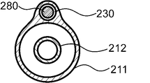
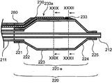
- FIG. 13 shows an overall view of the second balloon catheter 200 according to the embodiment of the present invention.
- FIG. 14 shows a plan view of the distal portion of the second balloon catheter 200 shown in FIG. 13 as viewed from the lumen side.
- FIG. 15 shows an XV-XV cross-sectional view of the second balloon catheter 200 shown in FIG.
- FIG. 16 represents a plan view of the distal portion of the second balloon catheter 200 according to another embodiment of the present invention as viewed from the lumen side.
- FIG. 17 shows a cross-sectional view of the second balloon catheter 200 shown in FIG. 16 XVII-XVII.
- FIG. 16 shows an overall view of the second balloon catheter 200 according to the embodiment of the present invention.
- FIG. 14 shows a plan view of the distal portion of the second balloon catheter 200 shown in FIG. 13 as viewed from the lumen side.
- FIG. 15 shows an XV-XV cross-sectional view of the second balloon catheter 200 shown in FIG.
- FIG. 16 represents a plan view of
- FIG. 18 represents an XVIII-XVIII cross-sectional view of the second balloon catheter 200 shown in FIG. 13, that is, a cross-sectional view perpendicular to the perspective of the portion where the lumen is arranged along the shaft.
- FIG. 19 represents a XIV-XIV cross-sectional view of the second balloon catheter 200 shown in FIG. 14, that is, a cross-sectional view perpendicular to the perspective direction of a portion where an opening is not arranged in the lumen.
- FIG. 20 shows a cross-sectional view showing another example of the XIV-XIV cross-sectional view of the second balloon catheter 200 shown in FIG. 14, and
- FIG. 21 shows the XVI- of the second balloon catheter 200 shown in FIG.
- FIG. 22 shows a cross-sectional view of XXII-XXII of the second balloon catheter 200 shown in FIG. 14, that is, a cross-sectional view perpendicular to the perspective direction of the portion where the opening is arranged in the lumen
- FIG. 23 is shown in FIG.
- a modified example of the cross-sectional view of the XXII-XXII of the second balloon catheter 200 shown is shown.
- FIG. 24 shows a cross-sectional view perpendicular to the perspective direction when the long body is not inserted into the second balloon catheter 200 shown in FIG. 22.
- FIG. 25 shows an enlarged view of the lumen portion of the cross-sectional view shown in FIG.
- FIG. 26 shows an enlarged view of the lumen portion of the cross-sectional view shown in FIG. 24.
- FIG. 27 shows a sectional view of the distal portion of the second balloon catheter 200 according to another embodiment of the present invention perpendicular to the perspective direction
- FIG. 28 shows a second embodiment according to still another embodiment of the present invention.
- FIG. 6 shows a cross-sectional view of the distal portion of the balloon catheter 200 perpendicular to the perspective direction.
- 29 shows a cross-sectional view of the second balloon catheter 200 shown in FIG. 27, and
- FIG. 30 shows a modified example of the cross-sectional view of the balloon catheter 200 shown in FIG. 27.
- FIG. 31 shows a cross-sectional view when the long body is not inserted into the second balloon catheter 200 shown in FIG. 29.
- FIG. 32 shows a cross-sectional view of the second balloon catheter 200 shown in FIG. 27, XXXII-XXXII.
- FIG. 33 shows a perspective view of a long body according to an embodiment of the present invention
- FIG. 34 shows a perspective view of a long body according to another embodiment of the present invention.
- the second balloon catheter 200 has a shaft 210 extending in the perspective direction and a balloon 220 provided on the distal side of the shaft 210. , A long body 280 extending in the perspective along the shaft 210 and the balloon 220, and a lumen 230 extending in the perspective along the shaft 210 and the balloon 220 through which the long body 280 can be inserted.
- the proximal end of the lumen 230 is located proximal to the shaft 210 with an insertion slot for the elongated body 280, and the balloon 220 is an extension that is not fixed to the shaft 210.
- the lumen 230 has an opening 230a extending radially outward in the extension 220e, and the proximal end of the opening 230a is the extension.
- the lumen 230 Arranged distal to the proximal end of the 220e, the lumen 230 has an opening distal to the proximal end of the lumen 230 and proximal to the proximal end of the opening 230a.
- the lumen 230 is engaged with the long body 280 so that the long body 280 does not rotate more than 60 degrees in the rotation direction about the perspective direction at least a part of the opening 230a.
- the distal side refers to the direction of the subject to be treated with respect to the extending direction of the shaft 210
- the proximal side is the opposite side of the distal side. That is, it refers to the direction on the user's hand side with respect to the extending direction of the shaft 210.
- the direction from the proximal side to the distal side and the direction from the distal side to the proximal side of the shaft 210 are referred to as a perspective direction.
- the long body 280 extends in the perspective direction along the shaft 210 and the balloon 220, and can be inserted into the lumen 230.
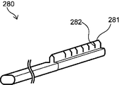
- the elongated body 280 may have a biological tissue contact portion 281 at the distal end acting on the living body, and the configuration thereof is shown in FIGS. 4 and 5 showing the elongated body 180 of the first balloon catheter 100. And the above description for the elongated body 180 can be referred to.
- the biological tissue contact portion 281 acts on the lesion portion to fix the balloon 220 to the lesion portion, and the biological tissue contact portion 281 can excise the stenotic portion or the like occurring in the lesion portion.
- the cross-sectional shape of the elongated body 280 that is perpendicular to the perspective direction of the portion where the living tissue contact portion 281 is not provided shall be, for example, a circular shape, an elliptical shape, a polygonal shape, a shape obtained by combining these, or any other shape. However, it is preferably circular. Here, the term "circle” does not mean only a perfect circle, but includes all circular shapes. If the cross-sectional shape of the long body 280 perpendicular to the perspective direction is circular in the portion where the living tissue contact portion 281 is not provided, the long body 280 can be easily inserted into the lumen 230.
- FIG. 33 the cross-sectional shape of the portion where the biological tissue contact portion 281 is not provided is circular, and the cross-sectional shape of the portion where the biological tissue contact portion 281 is provided is substantially fan-shaped.
- FIG. 34 shows a perspective view of the long body 280, which has an elliptical cross-sectional shape perpendicular to the perspective direction of the portion where the biological tissue contact portion 281 is not provided, and a portion where the biological tissue contact portion 281 is provided.
- a perspective view of a long body 280 having a convex cross-sectional shape perpendicular to the perspective direction of the above is shown.
- the cross-sectional shapes of the elongated body 280 perpendicular to the perspective direction may be different in the perspective direction.
- the distal end of the elongated body 280 may have a tapered shape. If the distal end of the elongated body 280 has a tapered shape, it is easy to insert the elongated body 280 into the lumen 230, or the distal end of the elongated body 280 after delivery to the lesion. This has the effect of reducing the risk of damaging living tissue.
- the major axis d of the long body 280 in the cross section perpendicular to the perspective direction is preferably 0.1 mm or more, more preferably 0.15 mm or more, still more preferably 0.2 mm or more.
- the major axis d of the long body 280 is preferably 1 mm or less, more preferably 0.9 mm or less, and even more preferably 0.8 mm or less.
- the major axis d of the elongated body 280 is within the above range, it becomes easy to insert the elongated body 280 into the lumen 230, and the balloon 220 is inserted into the lesion portion without deteriorating the insertability of the second balloon catheter 200. Can be delivered to.
- the major axis is the diameter of a virtual circle inscribed by a cross section perpendicular to the perspective direction of the elongated body 280, and if the cross section perpendicular to the perspective direction of the elongated body 280 is circular, the diameter of the circle. The diameter.
- the elongated body 280 has a portion where the living tissue contact portion 281 is provided and a portion where the living tissue contact portion 281 is not provided, and the cross-sectional shape perpendicular to the perspective direction differs depending on the location in the perspective direction. Therefore, the major axis d may be different in the perspective direction, but it is preferable that the major axis d is within the above range in any cross section.
- FIG. 4 showing the elongated body 180 of the first balloon catheter 100 can be referred to.
- Examples of the material constituting the long body 280 include metals such as stainless steel, titanium, nickel-titanium alloy, cobalt-chromium alloy, and tungsten alloy; polyarylate fiber, aramid fiber, ultrahigh molecular weight polyethylene fiber, PBO fiber, and carbon fiber. Fiber materials made of synthetic resins such as, and ceramics made of alumina, zirconia, barium titanate, etc. can be mentioned. Only one type of these may be used, two or more types may be used in combination, and the fiber material may be monofilament or multifilament.
- the lumen 230 may extend in the perspective direction along the shaft 210 and the balloon 220, and particularly in the portion along the balloon 220, the lumen 230 is arranged straight without having an angle with respect to the central axis of the balloon 220. It may be arranged spirally at an angle with respect to the central axis of the balloon 220.
- the arrangement of the lumen 230 along the balloon 220 such as a linear shape or a spiral shape, may be selected in an optimum manner according to the lesion portion to be treated.
- the proximal end of the lumen 230 is located proximal to the shaft 210 and is provided with an insertion slot for a long body 280 (not shown).
- the long body 280 can be inserted from this insertion port, and the long body 280 can be inserted into the lumen 230.
- the elongated body 280 may be placed in the lumen 230 from the beginning, or may be inserted after the balloon 220 has been delivered to the lesion. Further, it is preferable that the long body 280 is slidable in the lumen 230.
- the elongated body 280 is arranged for fixing the balloon 220 to the lesion or excising the stenosis or the like occurring in the lesion, but the elongated body 280 is slidable in the lumen 230. By being there, the elongated body 280 can be arranged at an arbitrary perspective position. Further, in the embodiment in which the elongated body 280 is inserted into the lumen 230 after the balloon 220 is delivered to the lesion portion, the balloon 220 is easily facilitated without reducing the passage of the balloon 220 into the blood vessel due to the rigidity of the elongated body 280. It is preferable because it can be delivered to the lesion.
- the elongated body 280 By arranging the elongated body 280 on the lumen 230 along the shaft 210 and the balloon 220, the elongated body 280 is guided by the lumen 230, and the elongated body 280 causes an unintended deviation in the circumferential direction of the shaft 210 and the balloon 220. Prevent it from occurring and being inserted. This makes it possible to deliver the elongated body 280 to the desired position. In particular, by arranging the elongated body 280 in the lumen 230 along the balloon 220 delivered to the lesion, it is possible to prevent the elongated body 280 from being unintentionally displaced in the circumferential direction in the lesion.
- the deviation of the long body 280 in the circumferential direction means that the long body 280 moves in an unintended direction on the outer surface of the balloon 220. Therefore, when the lumen 230 is spirally arranged along the balloon 220 at an angle with respect to the central axis of the shuttle 210, the elongated body 280 inserted through the lumen 230 is the perspective of the balloon 220. It will proceed spirally with respect to the direction, but this does not correspond to the fact that the elongated body 280 is displaced in the circumferential direction of the balloon 220. The deviation means that the long body 280 moves in an unintended direction.
- the cross-sectional shape perpendicular to the perspective direction in the portion of the lumen 230 that does not have the opening 230a may be circular.
- the term "circular” does not mean only a perfect circle, but includes all circular shapes.
- the cross-sectional shape of the lumen 230 perpendicular to the perspective direction may be an ellipse, a polygon, a combination thereof, or any other shape.
- the lumen 230 may have different cross-sectional shapes in the perspective direction.
- the cross-sectional shape of the lumen 230 perpendicular to the perspective direction is preferably circular.
- the cross-sectional shape of the lumen 230 along the shaft 210 is circular, the long body 280 can be easily inserted.
- the cross-sectional shape of the portion of the lumen 230 that does not have the opening 230a, which is perpendicular to the perspective direction may be circular as shown in FIGS. 19 to 21, or the above. It may have an arbitrary shape, or may have a shape corresponding to the cross-sectional shape of the long body 280 arranged in the lumen 230.
- the cross-sectional shape of the lumen 230 perpendicular to the perspective direction corresponds to the cross-sectional shape of the long body 280, the axial rotation of the long body 280 at the portion of the lumen 230 that does not have the opening 230a along the balloon 220. Is preferable because it can suppress the above to some extent.
- the major axis of the cross section of the lumen 230 perpendicular to the perspective direction is preferably 0.2 mm or more, more preferably 0.3 mm or more, and further preferably 0.5 mm or more.
- the major axis of the cross section of the lumen 230 perpendicular to the perspective direction is preferably 1.2 mm or less, more preferably 1 mm or less, and even more preferably 0.8 mm or less.
- the major axis of the cross section perpendicular to the perspective direction of the lumen 230 is the diameter of the virtual circle inscribed by the cross section perpendicular to the perspective direction of the lumen 230, similarly to the major axis d of the elongated body 280, and the perspective of the lumen 230. If the cross section perpendicular to the direction is circular, it is the diameter of the circle.
- the cross-sectional shape perpendicular to the perspective direction may be different depending on the location in the perspective direction, and the major axis of the cross section may be different, but the major axis is in the above range in any of the cross sections. It is preferably inside.
- 19 to 21 are XIX-XIX cross-sectional views of the second balloon catheter 200 shown in FIG. 14 in different embodiments, and is a cross-sectional view of a portion of the lumen 230 along the balloon 220 that does not have an opening 230a.
- the figure is shown.
- only one lumen 230 may be provided, or a plurality of lumens 230 may be provided as shown in FIG.
- the number of lumens 230 is 1 or more, may be 2 or more, and may be 3 or more.
- the number of lumens 230 is preferably 6 or less, more preferably 5 or less, and even more preferably 4 or less.
- the lumen 230 may be formed radially outward with respect to the balloon 220.
- the guided elongated body 280, a drug, or the like can be arranged radially outward of the balloon 220, and the elongated body 280 can be arranged. And drugs can easily act on the lesion.
- at least a part of the lumen 230 may be formed on the outer side in the radial direction of the balloon 220, and the other part may be formed on the inner side of the balloon 220. This is preferable because the outer diameter of the balloon 220 and the lumen 230 combined can be kept small and the insertability in the blood vessel can be improved.
- the above configuration is the same for the portion where the lumen 230 is along the shaft 210.
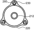
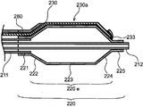
- the balloon 220 is arranged on the extension portion 220e not fixed to the shaft 210, the proximal side fixing portion 221 arranged on the proximal side of the expansion portion 220e and connected to the shaft 210, and the distal side of the expansion portion 220e. It has a distal side fixing portion 225 connected to the shaft 210, and as shown in FIGS. 13 to 17, the lumen 230 is near and far outward in the radial direction of the balloon 220 in the expansion portion 220e. It has an opening 230a extending in the direction, and the proximal end of the opening 230a is located distal to the proximal end of the extension 220e.
- a part of the elongated body 280 is exposed from the opening 230a, and the exposed elongated body 280 can act on the lesion portion.
- those parts are also included in the proximal side fixing part 221 and the distal side fixing part 225.
- the distal end of the opening 230a may be the distal end 230d of the lumen 230.
- the distal end 230d of the lumen 230 has an outlet through which the elongated body 280 can move forward and backward, and the distal side of the elongated body 280 may be exposed from the outlet.
- the distal end 230d of the lumen 230 may be arranged distal to the distal end of the opening 230a. That is, a lumen 230 having no opening is arranged beyond the distal end of the opening 230a, guides the elongated body 280 beyond the opening 230a, and is provided at the distal end 230d of the lumen 230.
- the distal side of the elongated body 280 may be exposed from the outlet.
- the elongated body 280 is repeatedly expanded and contracted while advancing the balloon 220.
- the lesion can be treated by a crawling forward technique or the like in which an incision is made with a balloon.
- the expansion portion 220e includes a straight pipe portion 223, a proximal taper portion 222 arranged on the proximal side of the straight pipe portion 223, and a distal taper portion arranged on the distal side of the straight pipe portion 223. It has 224, and as shown in FIGS. 14 to 17, it is preferable that the proximal end of the opening 230a is arranged in the proximal tapered portion 222. It is preferable that the proximal taper portion 222 and the distal taper portion 224 are formed so as to reduce in diameter as the distance from the straight pipe portion 223 increases.
- the balloon 220 Since the balloon 220 has the straight tube portion 223, it is possible to sufficiently secure a portion of the straight tube portion 223 where the balloon 220 can expand most in the radial direction in contact with the lesion portion, and the balloon 220 is formed in the lesion portion. It becomes easier to expand the narrowed part. Further, since the balloon 220 has a proximal side tapered portion 222 and a distal side tapered portion 224 that reduce in diameter as the distance from the straight pipe portion 223 increases, when the balloon 220 is contracted and wound around the shaft 210, Since the outer diameters of the proximal end and the distal end of the balloon 220 can be reduced to reduce the step between the shaft 210 and the balloon 220, the balloon 220 can be easily inserted into the blood vessel.
- the elongated body 280 can be exposed from the opening 230a from the proximal tapered portion 222 to the straight pipe portion 223, so that the elongated body 280 can be exposed in a wide range.
- the body 280 can be exposed to effectively treat the lesion.
- the proximal end of the opening 230a may be located in the straight pipe portion 223. Since the elongated body 280 can be exposed in the straight tube portion 223 in which the balloon 220 can be expanded most in the radial direction and a portion in contact with the lesion portion can be sufficiently secured, the lesion portion can be effectively treated.
- the distal end of the opening 230a may be located in the straight tube portion 223 or in the distal tapered portion 224. If the distal end of the opening 230a is located in the straight tube 223, the elongated body 280 is exposed in the straight tube 223 where the balloon 220 can be expanded most in the radial direction and a portion in contact with the lesion can be sufficiently secured. Can be made to. If the distal end of the opening 230a is located at the distal taper 224, the elongated body 280 can be exposed at the distal end of the balloon 220.
- the perspective length of the opening 230a is preferably 1/10 or more, more preferably 1/5 or more, and even more preferably 1/2 or more of the perspective length of the expansion portion 220e. Further, the length of the opening 230a in the perspective direction is preferably 1 time or less, more preferably 9/10 or less, further preferably 4/5 or less, and 2/3 or less of the length of the expansion portion 220e in the perspective direction. There may be. Further, the opening 230a may be continuously provided or discontinuously provided in the expansion 220e. When the perspective length of the opening 230a is within the above range with respect to the perspective length of the expansion 220e, the elongated body 280 can be exposed from the opening 230a to treat the lesion.
- the lumen 230 does not have an opening between the proximal end of the lumen 230 and the proximal end of the opening 230a. Since the lumen 230 does not have an opening in the above range, it prevents the elongated body 280 from being exposed where it is not needed, protects the elongated body 280, and prevents damage to living tissue by the elongated body 280. Can be done.
- the lumen 230 is engaged with the long body 280 so that the long body 280 does not rotate more than 60 degrees in the rotation direction about the perspective direction at least a part of the portion having the opening 230a. It has two engaging portions 231.
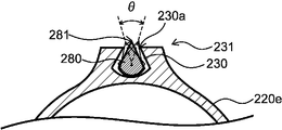
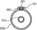
- FIG. 22 is a cross-sectional view perpendicular to the perspective direction of the second engaging portion 231 with which the long body 280 is engaged
- FIG. 23 is a perspective view of the second engaging portion 231 with which the long body 280 is engaged.
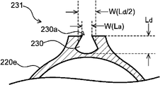
- FIG. 24 shows a cross-sectional view perpendicular to the perspective direction of the opening 230a in the second engaging portion 231 shown in FIG. 22, and FIG.
- FIG. 25 shows an enlarged view of the lumen 230 portion of the cross-sectional view shown in FIG.
- the fact that the lumen 230 and the long body 280 are engaged so as to hinder the rotation of the long body 280 means that the lumen 230 hinders the axial rotation of the long body 280 in the perspective direction. It means that the movement of the long body 280 is restricted, but not only when the lumen 230 and the long body 280 are fixed to each other so as to prevent any rotation as shown in FIG. 23, FIG. 22 Also, as shown in FIG. 25, the lumen 230 restricts the movement of the long body 280 to such an extent that the long body 280 has some play in the rotation direction about the perspective direction.
- the long body 280 does not rotate about 60 degrees or more in the rotation direction about the perspective direction in the second engaging portion 231.
- the angle ⁇ of the axial rotation of the long body 280 is such that the line connecting one of the points where the long body 280 touches the circumscribed circle and the center of gravity of the long body 280 rotates in the axial direction of the long body 280. It can be determined by measuring.
- FIG. 25 shows an example in which one of the points where the long body 280 touches the circumscribed circle is the living tissue contact portion 281. However, one point among the points where the long body 280 touches the circumscribed circle is unique. Therefore, the angle ⁇ of the axial rotation point can be obtained.
- the angle ⁇ of the axial rotation of the long body 280 in the second engaging portion 231 is more preferably 40 degrees or less, further preferably 20 degrees or less, and most preferably 0 degrees (that is, there is no play).
- the long body 280 can rotate about the axis in the range of 5 degrees or more and 60 degrees or less.
- the elongated body 280 is more preferably axially rotatable by 7 degrees or more, and may be 10 degrees or more, 12 degrees or more, or 15 degrees or more.
- the axial rotation angle of the long body 280 in the second engaging portion 231 is within the above range, it is possible to facilitate the insertion into the body cavity while controlling the axial rotation of the long body 280. It can be easily inserted even at the bent portion of the body cavity without being disengaged.
- the lumen 230 is long because at least a part of the portion having the opening 230a has a second engaging portion 231 that is engaged with the elongated body 280 so as to prevent the elongated body 280 from rotating.
- the axial rotation of the long body 280 can be prevented at the portion where a part of the long body 280 is exposed and acts on the living tissue, and the long body 280 can be brought into contact with the living tissue at a desired angle.
- the width W (L a) at the opening 230a of the lumen 230 has a width W at half the depth of the lumen depth L d (part of the L d / 2) (L d / Smaller than 2).
- FIG. 26 shows an example of the width W (L a ) at the opening 230 a of the lumen 230 and the width W (L d / 2) at half the depth (L d / 2) of the lumen depth L d. ..
- the second engaging portion 231 may be continuously arranged in the perspective direction from the proximal end to the distal end of the opening 230a of the lumen 230, or distal from the proximal end of the opening 230a of the lumen 230. It may be located in a part between the edges.
- the perspective length of the second engaging portion 231 is the opening 230a.
- the length in the perspective direction is preferably 10% or more, more preferably 20% or more, further preferably 30% or more, and particularly preferably 50% or more. If the perspective length of the second engaging portion 231 is greater than or equal to the above-mentioned length of the opening 230a in the perspective direction, it is possible to prevent the axial rotation of the elongated body 280.
- the lumen 230 is engaged with the portion of the long body 280 other than the biological tissue contact portion 281 in the second engaging portion 231.
- the living tissue contact portion 281 can be exposed from the opening 230a without being hindered by the engagement with the living tissue 230, and the living tissue contact portion 281 can be exposed. Can be brought into contact with the lesion.
- the living tissue contact portion 281 is arranged outside the opening 230a in the radial direction of the expansion portion 220e.
- the biological tissue contact portion 281 is arranged outside the opening 230a in the radial direction of the expansion portion 220e in a natural state in which pressure is not applied to the balloon 220 or the lumen 230.
- the balloon 220 can be delivered to the lesion and then the elongated body 280 can be inserted through the lumen 230 and delivered to the lesion, the living tissue contact portion 281 can be delivered to the lesion in a natural state. Even if it is arranged outside the opening 230a in the radial direction of 220e, the treatment can be performed without unnecessarily abutting or damaging the living tissue.
- the lumen 230 does not have a concave portion or a convex portion extending in the longitudinal direction in the lumen. That is, the lumen 230 has, for example, a concave portion into which the protruding portion formed in the elongated body 280 enters and a convex portion entering into the groove portion formed in the elongated body 280 as a means for forming the second engaging portion 231. It is preferable that there is no such thing. Since the lumen 230 does not have a concave portion or a convex portion extending in the longitudinal direction in the lumen, the second engaging portion 231 can be provided while easily inserting the long body 280 into the lumen 230. it can. As a result, the long body 280 can be rotated in a range of 60 degrees or less, and the long body 280 can be flexibly inserted into the lumen 230 even in a bent body cavity.
- the cross-sectional shape of the lumen 230 perpendicular to the perspective direction continuously changes in the section from the point proximal to the second engaging portion 231 to the second engaging portion 231 in the perspective direction. If the second engaging portion 231 is formed by such continuous changes, the shaft rotation is gradually controlled in the process of guiding the long body 280 to the second engaging portion 231, and the second engaging portion is formed. At 231 the elongated body 280 is preferred because it is easily engaged with the lumen 230.
- the lumen 230 is located distal to the distal end of the opening 230a at the same position as the distal end of the elongated body 280 or from the distal end of the elongated body 280.
- the stopper 233 may be arranged in the straight pipe portion 223 as shown in FIG. 27, may be arranged in the distal taper portion 224 as shown in FIG. 28, or may be arranged in the distal side taper portion 224 as shown in FIG. It may be arranged in the side fixing portion 225. Depending on where the stopper 233 is placed and where the distal end of the opening 230a is placed, it is possible to select where in the balloon 220 the elongated body 280 is exposed. For example, as shown in FIG. 28, if the stopper 233 is arranged on the distal taper portion 224 and the distal end of the opening 230a is also arranged on the distal taper portion 224, the elongated body 280 is straightened.
- the lesion portion can be exposed by a swelling forward technique or the like in which the balloon 220 is repeatedly expanded and contracted while the balloon 220 is advanced to make an incision with a long body 280. Can be treated.
- the means for providing the stopper 233 is not particularly limited, but for example, the lumen 230 provided as shown in FIG. 31 can be provided by crushing as shown in FIG. 32.
- the long body 280 inserted through the lumen 230 as shown in FIGS. 29 and 30 crushes the lumen 230 as shown in FIG. 32, the crushed portion of the lumen 230 becomes a stopper 233 and becomes long.
- the scale 280 does not progress distal to it.
- FIG. 29 shows an aspect in which there is play in the axial rotation of the long body 280 in the second engaging portion 231
- FIG. 30 shows a play in the axial rotation of the long body 280 in the second engaging portion 231.
- the stopper 233 can prevent the elongated body 280 from advancing to the distal side.
- the long body 280 arranged in the expansion portion 220e is provided with one or more notches 282.
- the number of cuts 282 is preferably 2 or more, more preferably 3 or more, further preferably 5 or more, and the number of cuts 282 is preferably 20 or less, more preferably 15 or less, still more preferably 12 or less. Within the range of the number of cuts 282, the flexibility can be improved without impairing the strength of the long body 280.
- the notch 282 is provided on the side of the elongated body 280 where the biological tissue contact portion 281 is provided.
- the orientation and size of the notch 282 are not limited as long as the flexibility can be improved without impairing the strength of the elongated body 280.
- the notch 282 may be provided at an angle perpendicular to or other than the axial direction of the elongated body 280, and each of the plurality of notches 282 provided as shown in FIG. 33 is provided with respect to the axial direction of the elongated body 280. It may be provided at different angles, or as shown in FIG.
- each of the plurality of notches 282 may be provided at the same angle with respect to the axial direction of the elongated body 280.
- FIG. 13 shows a configuration example of a so-called over-the-wire type balloon catheter 200 in which a guide wire for guiding the progress of the balloon catheter 200 is inserted from the distal side to the proximal side of the shaft 210.
- the second balloon catheter 200 can also be applied to a so-called rapid exchange type balloon catheter in which a guide wire is inserted halfway from the distal side to the proximal side of the shaft 210.
- the balloon catheter 200 is configured so that fluid is supplied to the inside of the balloon 220 through the shaft 210, and the expansion and contraction of the balloon 220 can be controlled by using an indeflator (balloon pressurizer).
- the fluid may be a pressure fluid pressurized by a pump or the like.
- a fluid flow path is provided inside the shaft 210. Further, it is preferable that the shaft 210 has a guide wire insertion passage inside.
- the shaft 210 has an outer pipe 211 and an inner pipe 212.
- the inner pipe 212 functions as an insertion passage for a guide wire, and the space between the inner pipe 212 and the outer pipe 211 functions as a fluid flow path.
- the inner tube 212 extends from the distal end of the outer tube 211 and penetrates the balloon 220 in the perspective direction, and the proximal side of the balloon 220 is the outer tube 211. It is preferable that the balloon 220 is fixed to the inner tube 212 on the distal side.
- the material constituting the shaft 210 examples include polyamide-based resin, polyester-based resin, polyurethane-based resin, polyolefin-based resin, fluorine-based resin, vinyl chloride-based resin, silicone-based resin, and natural rubber. Only one type of these may be used, or two or more types may be used in combination. Above all, the material constituting the shaft 210 is preferably at least one of a polyamide resin, a polyolefin resin, and a fluorine resin. Since the material constituting the shaft 210 is at least one of a polyamide resin, a polyolefin resin, and a fluorine resin, the slipperiness of the surface of the shaft 210 is enhanced, and the passability of the balloon catheter 200 through the blood vessels is improved. be able to.
- Examples of the material constituting the balloon 220 include at least one selected from the group consisting of polyamide-based resin, polyester-based resin, polyurethane-based resin, polyolefin-based resin, vinyl chloride-based resin, silicone-based resin, and natural rubber. .. Of these, at least one selected from the group consisting of polyamide-based resins, polyester-based resins, and polyurethane-based resins is preferable. Moreover, you may use an elastomer resin as these resins.
- the balloon 220 can be manufactured by molding a resin.
- the balloon 220 can be manufactured by arranging a resin tube extruded by extrusion molding in a mold and performing biaxial stretching blow molding.
- the balloon 220 can also be manufactured by a known molding method such as dip molding, injection molding, or compression molding.
- the portion forming the lumen 230 along the balloon 220 is preferably integrally molded with the balloon 220.
- integrally molding the lumen 230 with the balloon 220 it becomes easy to form the lumen 230.
- the balloon 220 is manufactured by extrusion molding as described above while securing the lumen with a core material for forming the lumen or high-pressure air. Can be mentioned.
- the portion forming the lumen 230 along the shaft 210 may be integrally formed with the shaft 210, or may be formed by a tubular member different from the shaft 210 and joined to the shaft 210. If the portion forming the lumen 230 along the shaft 210 is integrally molded with the shaft 210, it becomes easy to form the lumen 230 by extrusion molding or the like as in the portion along the balloon 220. Further, if the portion forming the lumen 230 along the shaft 210 is formed by a tubular member different from the shaft 210, comparison can be made regardless of the shape of the lumen 230 along the shaft 210. It can be easily manufactured.
- the material constituting the tubular member can refer to the material constituting the shaft 210, and may be the same as or different from the material constituting the shaft 210.
- the shaft 210 and the tubular member can be joined by an existing method such as adhesion with an adhesive or welding.
- the dimensions of the balloon 220 are preferably 5 mm to 300 mm in the perspective direction and 0.5 mm to 12 mm in the outer diameter when the lesion is a blood vessel, and when the lesion is a gastrointestinal tract such as the duodenal papilla. It is preferable that the length in the perspective direction is 10 mm to 100 mm and the outer diameter is 3 mm to 30 mm.
- Fixing of the shaft 210 and the balloon 220 includes, for example, adhesion and welding with an adhesive, and caulking by attaching a ring-shaped member to a portion where the shaft 210 and the end of the balloon 220 overlap. Above all, it is preferable that the shaft 210 and the balloon 220 are fixed by welding. Since the shaft 210 and the balloon 220 are welded together, the fixing between the shaft 210 and the balloon 220 is difficult to be released even if the balloon 220 is repeatedly expanded and contracted, and the fixing strength between the shaft 210 and the balloon 220 is easily increased. be able to.
- the balloon catheter 200 may have a hub 204 on the proximal side of the shaft 210 to deliver fluid to the shaft 210.
- the hub 204 preferably has a fluid injection portion 206 communicating with the fluid flow path supplied inside the balloon 220 and a guide wire insertion portion 205 communicating with the guide wire insertion passage. Since the balloon catheter 200 has a hub 204 including a fluid injection portion 206 and a guide wire insertion portion 205, an operation of supplying fluid to the inside of the balloon 220 to expand and contract the balloon 220 and along the guide wire can be performed.
- the balloon catheter 200 can be easily delivered to the lesion.
- Fixing of the shaft 210 and the hub 204 includes, for example, adhesion with an adhesive, welding, and the like. Above all, it is preferable that the shaft 210 and the hub 204 are fixed by adhesion. If the shaft 210 and the hub 204 are fixed by adhesion, for example, the shaft 210 is made of a highly flexible material, the hub 204 is made of a highly rigid material, and so on. When the material constituting the hub 204 is different, the fixing strength between the shaft 210 and the hub 204 can be increased to increase the durability of the balloon catheter 200.
- a chemical injection port may be provided in the proximal portion of the shaft 210.
- the drug solution injected from the drug solution injection port is introduced into the lumen 230 by a tube communicating with the lumen 230, and is discharged from the distal end 230d of the lumen 230 and / or the opening 230a provided in the lumen 230 to form a lesion. Can be administered to.
- the drug solution can be injected after the balloon 220 is delivered to the lesion and the drug solution can be delivered to the lesion by the lumen 230. It is possible to effectively administer the drug to the lesion without losing the drug in the drug solution during delivery.
- the drug contained in the drug solution injected from the drug solution injection port is not particularly limited as long as it is a pharmacologically active substance, and examples thereof include non-gene therapy drugs, gene therapy drugs, small molecules, cells, and other drugs that are acceptable as drugs. Be done.
- anti-restenosis agents such as antiproliferative agents and immunosuppressive agents can be preferably used as agents.
- drugs such as paclitaxel, sirolimus (rapamycin), everolimus, and zotarolimus can be used. Only one of these agents may be used, or two or more of these agents may be used.
- the third balloon catheter may be a balloon catheter having both a first engaging portion 131 and a second engaging portion 231, or a second balloon catheter 200 having a first engaging portion 131. It may be a balloon catheter with preferred requirements.
- Such a balloon catheter can prevent the long body from rotating in the axial direction and shifting in the circumferential direction on the balloon, and can bring the long body into contact with the lesion at a desired angle.
- First balloon catheter 104 Hub 105 of the first balloon catheter: Guide wire insertion part 106 of the first balloon catheter: Fluid injection part 110 of the first balloon catheter: Shaft 111 of the first balloon catheter: Outer tube of the shaft of the first balloon catheter 112: Inner tube of the shaft of the first balloon catheter 120: Balloon 120e of the first balloon catheter: Expansion portion of the first balloon catheter 120f: Fixation of the first balloon catheter Part 121: Proximal taper portion 122 of the first balloon catheter: Straight tube portion 123 of the first balloon catheter: Distal taper portion 130 of the first balloon catheter: Lumen 130d for long body: Long body Distal end 131 of the lumen for use: First engaging portion 180: Elongated body of the first balloon catheter 181: Living tissue contact portion of the first balloon catheter 200: Second balloon catheter 204: Second balloon catheter Hub 205: Guide wire insertion part of the second balloon catheter 206: Fluid injection part of the second balloon catheter 210: Shaft of the second balloon catheter 211: Outer tube of the shaft of the second balloon
Abstract
Provided is a balloon catheter whereby rotation of a long shaft or deviation in the circumferential direction of the balloon is suppressed while passage of the balloon in a blood vessel is improved, and a long body can be brought into contact with a lesion at the expected angle. A balloon catheter (100) comprising a shaft (110) and a balloon (120), the balloon catheter (100) having a long body (180) which extends along the shaft (110) and which has a biotissue contact part in a distal-end part thereof, and a long-body lumen (130), the long-body lumen (130) having a first engaging part (131) in which the angle of axial rotation of the long body (180) is 0 to 60 degrees inclusive, and the first engaging part (131) being positioned between a distal end (130d) of the long-body lumen (130) and a location 30 cm toward the proximal side from the distal end (130d).
Description
本発明は、長尺体を有するバルーンカテーテルに関する。
The present invention relates to a balloon catheter having a long body.
体内で血液が循環するための流路である血管に狭窄が生じ、血液の循環が滞ることにより様々な疾患が発生することが知られている。特に心臓に血液を供給する冠状動脈に狭窄が生じると、狭心症、心筋梗塞等の重篤な疾病をもたらすおそれがある。このような血管の狭窄部を治療する方法として、経皮的血管形成術(PTA)や経皮的冠動脈形成術(PTCA)といった血管形成術等の、バルーンカテーテルを用いて狭窄部を拡張させる手技がある。血管形成術は、バイパス手術のような開胸術を必要としない低侵襲療法であり、広く行われている。
It is known that stenosis occurs in blood vessels, which are the flow paths for blood circulation in the body, and various diseases occur due to the stagnation of blood circulation. In particular, stenosis of the coronary arteries that supply blood to the heart may lead to serious diseases such as angina pectoris and myocardial infarction. As a method for treating such a stenotic part of a blood vessel, a procedure for dilating the stenotic part using a balloon catheter such as angioplasty such as percutaneous angioplasty (PTA) or percutaneous coronary angioplasty (PTCA). There is. Angioplasty is a minimally invasive therapy that does not require thoracotomy, such as bypass surgery, and is widely practiced.
血管内壁には、石灰化等により硬化した狭窄部が形成される場合がある。このような石灰化病変部においては、一般的なバルーンカテーテルでは硬化した狭窄部を拡張させにくい。また、ステントと称される留置拡張器具を血管の狭窄部に留置することによって狭窄部を拡張させる方法も用いられているが、この治療後に血管の新生内膜が過剰に増殖して再び血管の狭窄が発生してしまうISR(In-Stent-Restenosis)病変が起こる場合がある。ISR病変においては、新生内膜が柔らかく、また表面が滑りやすいため、一般的なバルーンカテーテルではバルーンの拡張時にバルーンの位置が病変部からずれてしまい、血管を傷つけてしまうことがある。
A stenosis hardened due to calcification or the like may be formed on the inner wall of the blood vessel. In such a calcified lesion, it is difficult to dilate the hardened stenosis with a general balloon catheter. In addition, a method of dilating the stenosis by placing an indwelling dilation device called a stent in the stenosis of the blood vessel is also used. ISR (In-Stent-Restenosis) lesions that cause stenosis may occur. In ISR lesions, the neointima is soft and the surface is slippery, so with a general balloon catheter, the position of the balloon may shift from the lesion when the balloon is expanded, and the blood vessel may be damaged.
このような石灰化病変やISR病変であっても狭窄部を拡張できるバルーンカテーテルとして、バルーンがスコアリングエレメントを有しているバルーンカテーテルがある。スコアリングエレメントとは、バルーンを血管内壁に固定したり、血管内壁の石灰化部位に亀裂を入れたり、石灰化部位を切除することで狭窄を解消したりするために用いられる部材であり、通常、固定や切除のための刃状部を有している。
As a balloon catheter capable of expanding the stenosis even in such a calcified lesion or an ISR lesion, there is a balloon catheter in which the balloon has a scoring element. A scoring element is a member used to fix a balloon to the inner wall of a blood vessel, crack a calcified site on the inner wall of a blood vessel, or remove the calcified site to eliminate stenosis. It has a blade-like part for fixing and cutting.
このようなスコアリングエレメントを有するバルーンカテーテルとして、例えば特許文献1及び2に挙げるようなものがある。また、切開要素が取り付けられたバルーンを治療部位へ搬送する際に切開要素を保護するために、バルーンにシースが取り付けられたバルーンカテーテルや(特許文献3)、切断器具を通過させる管腔を有するバルーンカテーテル(特許文献4)が開示されている。
As a balloon catheter having such a scoring element, for example, there are those listed in Patent Documents 1 and 2. Further, in order to protect the incision element when the balloon to which the incision element is attached is conveyed to the treatment site, it has a balloon catheter having a sheath attached to the balloon (Patent Document 3) and a cavity through which a cutting device is passed. A balloon catheter (Patent Document 4) is disclosed.
スコアリングエレメントは、石灰化した硬い病変部に作用する必要があるため、通常金属等の高い剛性を有する材料で形成されることが多い。そのため、スコアリングエレメントを初めからバルーンに固定した状態でバルーンを血管に挿入すると、スコアリングエレメントの剛性のためにバルーンの血管内での通過性が悪くなってしまうおそれがある。そこで、バルーンを収縮状態で血管内に挿入した後に長尺体のスコアリングエレメントを病変部まで送達する方法が取られることがある。このとき、スコアリングエレメントの刃状部を血管壁に固定したり刃状部により病変部を切除したりするためには、刃状部を所期の角度で血管壁に当接させる必要があるが、従来のバルーンカテーテルでは送達の途中でスコアリングエレメントが軸回転したり、送達時にスコアリングエレメントがバルーンの周方向にずれたり等のため、スコアリングエレメントの刃状部を所望する角度で血管内壁の病変部に当接させることができないという課題があった。
Since the scoring element needs to act on the calcified hard lesion, it is usually formed of a material having high rigidity such as metal. Therefore, if the balloon is inserted into the blood vessel with the scoring element fixed to the balloon from the beginning, the passage of the balloon in the blood vessel may be deteriorated due to the rigidity of the scoring element. Therefore, a method may be adopted in which a long scoring element is delivered to the lesion after the balloon is inserted into the blood vessel in a contracted state. At this time, in order to fix the blade-shaped portion of the scoring element to the blood vessel wall or excise the lesion portion by the blade-shaped portion, it is necessary to bring the blade-shaped portion into contact with the blood vessel wall at a desired angle. However, with conventional balloon catheters, the scoring element rotates around the axis during delivery, and the scoring element shifts in the circumferential direction of the balloon during delivery. There was a problem that it could not be brought into contact with the lesion on the inner wall.
本発明は、上記の事情に鑑みてなされたものであり、バルーンの血管内での通過性を良好としつつ、送達時における長尺体の軸回転やバルーン上での周方向へのずれを抑制して、長尺体を所期の角度で病変部に当接させることのできるバルーンカテーテルを提供することを課題とする。
The present invention has been made in view of the above circumstances, and while improving the passage of the balloon in the blood vessel, it suppresses the axial rotation of the long body at the time of delivery and the displacement in the circumferential direction on the balloon. An object of the present invention is to provide a balloon catheter capable of bringing a long body into contact with a lesion at a desired angle.
上記課題を解決する本発明の第1のバルーンカテーテルの一実施形態は、以下の構成からなる。
[1]遠近方向に延在しているシャフトと、上記シャフトの遠位側に設けられているバルーンと、を備えるバルーンカテーテルであって、
上記シャフトに沿って遠近方向に延在しており遠位端部に生体組織接触部を有している長尺体と、上記長尺体を挿通可能な長尺体用ルーメンと、を有しており、
上記長尺体用ルーメンは、上記長尺体の軸回転の角度が0度以上60度以下となるように上記長尺体に係合している第1係合部を有しており、上記第1係合部は上記長尺体用ルーメンの遠位端と該遠位端から近位側に30cmの地点との間に配置されていることを特徴とするバルーンカテーテル。 One embodiment of the first balloon catheter of the present invention that solves the above problems has the following configuration.
[1] A balloon catheter comprising a shaft extending in the perspective direction and a balloon provided on the distal side of the shaft.
It has a long body extending in the perspective direction along the shaft and having a living tissue contact portion at the distal end, and a lumen for a long body through which the long body can be inserted. And
The lumen for a long body has a first engaging portion that is engaged with the long body so that the axial rotation angle of the long body is 0 degrees or more and 60 degrees or less. A balloon catheter characterized in that the first engaging portion is arranged between the distal end of the long body lumen and a point 30 cm proximal to the distal end.
さらに本発明に係る第1のバルーンカテーテルには、好ましくは以下の[2]~[16]の構成も含まれる。
[2]上記第1係合部において、上記長尺体は5度以上60度以下の範囲で軸回転可能である[1]に記載のバルーンカテーテル。
[3]上記生体組織接触部は、上記第1係合部において上記シャフトの径方向の外方側に配置されている[1]又は[2]に記載のバルーンカテーテル。
[4]上記第1係合部において、遠近方向に垂直な上記長尺体の断面形状及び上記長尺体用ルーメンの断面形状は非円形である[1]~[3]のいずれかに記載のバルーンカテーテル。
[5]上記長尺体は、上記第1係合部より遠位側において遠近方向に垂直な断面形状が非円形である部分を有しており、上記長尺体用ルーメンは、上記第1係合部より近位側において遠近方向に垂直な断面形状が円形である部分を有している[1]~[4]のいずれかに記載のバルーンカテーテル。
[6]上記長尺体用ルーメンは内腔に長手軸方向に延在する凹部又は凸部を有していない[1]~[5]のいずれかに記載のバルーンカテーテル。
[7]遠近方向に垂直な上記長尺体用ルーメンの断面形状は、遠近方向において上記第1係合部よりも近位側の地点から上記第1係合部までの区間で連続的に変化している[1]~[6]のいずれかに記載のバルーンカテーテル。
[8]上記長尺体用ルーメンは、上記シャフトの径方向の同じ位置に配されるように上記シャフトに沿って延在している[1]~[7]のいずれかに記載のバルーンカテーテル。
[9]上記シャフトは上記シャフトの径方向の内側に面する内側面と外側に面する外側面とを有しており、上記長尺体用ルーメンは上記シャフトの上記内側面と上記外側面との間に形成されている[1]~[8]のいずれかに記載のバルーンカテーテル。
[10]上記長尺体用ルーメンは筒状部材により形成されており、上記筒状部材と上記シャフトとが接合されている[1]~[8]のいずれかに記載のバルーンカテーテル。
[11]上記第1係合部は、上記長尺体用ルーメンの遠位端に配置されている[1]~[10]のいずれかに記載のバルーンカテーテル。
[12]上記バルーンは、上記シャフトに固定されていない拡張部と、上記拡張部の遠位側及び近位側に配置され上記シャフトに接続されている固定部と、を有しており、上記長尺体用ルーメンの遠位端は上記拡張部よりも近位側に配置されている[1]~[11]のいずれかに記載のバルーンカテーテル。
[13]上記バルーンは、上記シャフトに固定されていない拡張部と、上記拡張部の遠位側及び近位側に配置され上記シャフトに接続されている固定部と、を有しており、上記拡張部は、直管部と、上記直管部の近位側に配置されている近位側テーパー部と、上記直管部の遠位側に配置されている遠位側テーパー部と、を有しており、上記長尺体用ルーメンの遠位端は上記近位側テーパー部に配置されている[1]~[11]のいずれかに記載のバルーンカテーテル。
[14]上記バルーンは、上記シャフトに固定されていない拡張部と、上記拡張部の遠位側及び近位側に配置され上記シャフトに接続されている固定部と、を有しており、上記拡張部は、直管部と、上記直管部の近位側に配置されている近位側テーパー部と、上記直管部の遠位側に配置されている遠位側テーパー部と、を有しており、上記長尺体用ルーメンの遠位端は上記直管部に配置されている[1]~[11]のいずれかに記載のバルーンカテーテル。
[15]上記長尺体の遠位端が先細りのテーパー形状を有している[1]~[14]のいずれかに記載のバルーンカテーテル。
[16]上記長尺体はスコアリングエレメントである[1]~[15]のいずれかに記載のバルーンカテーテル。 Further, the first balloon catheter according to the present invention preferably includes the following configurations [2] to [16].
[2] The balloon catheter according to [1], wherein in the first engaging portion, the elongated body can rotate around the axis in a range of 5 degrees or more and 60 degrees or less.
[3] The balloon catheter according to [1] or [2], wherein the biological tissue contact portion is arranged on the radial outer side of the shaft in the first engaging portion.
[4] In any of [1] to [3], the cross-sectional shape of the long body perpendicular to the perspective direction and the cross-sectional shape of the long body lumen in the first engaging portion are non-circular. Balloon catheter.
[5] The elongated body has a portion having a non-circular cross-sectional shape perpendicular to the perspective direction on the distal side of the first engaging portion, and the elongated body lumen has the first The balloon catheter according to any one of [1] to [4], which has a portion having a circular cross-sectional shape perpendicular to the perspective direction on the proximal side of the engaging portion.
[6] The balloon catheter according to any one of [1] to [5], wherein the lumen for a long body does not have a concave portion or a convex portion extending in the longitudinal direction in the lumen.
[7] The cross-sectional shape of the long body lumen perpendicular to the perspective direction continuously changes in the section from the point proximal to the first engaging portion to the first engaging portion in the perspective direction. The balloon catheter according to any one of [1] to [6].
[8] The balloon catheter according to any one of [1] to [7], wherein the lumen for a long body extends along the shaft so as to be arranged at the same position in the radial direction of the shaft. ..
[9] The shaft has an inner surface facing inward in the radial direction of the shaft and an outer surface facing the outer side, and the lumen for a long body has the inner surface and the outer surface of the shaft. The balloon catheter according to any one of [1] to [8] formed between the two.
[10] The balloon catheter according to any one of [1] to [8], wherein the lumen for a long body is formed of a tubular member, and the tubular member and the shaft are joined to each other.
[11] The balloon catheter according to any one of [1] to [10], wherein the first engaging portion is arranged at the distal end of the lumen for a long body.
[12] The balloon has an expansion portion that is not fixed to the shaft, and a fixing portion that is arranged on the distal side and the proximal side of the expansion portion and is connected to the shaft. The balloon catheter according to any one of [1] to [11], wherein the distal end of the lumen for a long body is arranged proximal to the extension.
[13] The balloon has an expansion portion that is not fixed to the shaft and a fixing portion that is arranged on the distal side and the proximal side of the expansion portion and is connected to the shaft. The expansion portion includes a straight pipe portion, a proximal taper portion arranged on the proximal side of the straight pipe portion, and a distal taper portion arranged on the distal side of the straight pipe portion. The balloon catheter according to any one of [1] to [11], wherein the distal end of the long body lumen is arranged in the proximal taper portion.
[14] The balloon has an expansion portion that is not fixed to the shaft and a fixing portion that is arranged on the distal side and the proximal side of the expansion portion and is connected to the shaft. The expansion portion includes a straight pipe portion, a proximal taper portion arranged on the proximal side of the straight pipe portion, and a distal taper portion arranged on the distal side of the straight pipe portion. The balloon catheter according to any one of [1] to [11], wherein the distal end of the long body lumen is arranged in the straight tube portion.
[15] The balloon catheter according to any one of [1] to [14], wherein the distal end of the elongated body has a tapered shape.
[16] The balloon catheter according to any one of [1] to [15], wherein the elongated body is a scoring element.
本発明はさらに第2のバルーンカテーテルを提供し、第2のバルーンカテーテルの一実施形態は以下の構成からなる。
[17]遠近方向に延在しているシャフトと、上記シャフトの遠位側に設けられているバルーンと、を有するバルーンカテーテルであって、
上記シャフト及び上記バルーンに沿って遠近方向に延在している長尺体と、上記シャフト及び上記バルーンに沿って遠近方向に延在しており上記長尺体を挿通可能なルーメンと、を有しており、
上記ルーメンの近位端は、上記長尺体の挿入口を備えて上記シャフトの近位部に配置されており、
上記バルーンは、上記シャフトに固定されていない拡張部と、上記拡張部の近位側に配置され上記シャフトと接続されている近位側固定部と、上記拡張部の遠位側に配置され上記シャフトと接続されている遠位側固定部と、を有しており、上記ルーメンは上記拡張部において径方向の外方側に遠近方向に延在している開口部を有しており、上記開口部の近位端は上記拡張部の近位端よりも遠位側に配置されており、
上記ルーメンは、上記ルーメンの近位端よりも遠位側及び上記開口部の近位端よりも近位側には開口部を有しておらず、
上記ルーメンは、上記開口部の少なくとも一部に上記長尺体が遠近方向を軸とした回転方向に60度以上回転しないように上記長尺体に係合している第2係合部を有しており、
上記第2係合部において、上記開口部での上記ルーメンの幅は、上記ルーメンの深さの1/2の箇所での上記ルーメンの幅よりも小さいことを特徴とするバルーンカテーテル。 The present invention further provides a second balloon catheter, and one embodiment of the second balloon catheter comprises the following configuration.
[17] A balloon catheter having a shaft extending in the perspective direction and a balloon provided on the distal side of the shaft.
It has a long body extending in the perspective direction along the shaft and the balloon, and a lumen extending in the perspective direction along the shaft and the balloon and allowing the long body to be inserted. And
The proximal end of the lumen is located proximal to the shaft with an insertion slot for the elongated body.
The balloon is arranged on the extension portion not fixed to the shaft, the proximal side fixing portion arranged on the proximal side of the expansion portion and connected to the shaft, and the distal side of the expansion portion. It has a distal side fixing part that is connected to the shaft, and the lumen has an opening that extends radially outward in the extension part and extends in the perspective direction. The proximal end of the opening is located distal to the proximal end of the extension.
The lumen has no openings distal to the proximal end of the lumen and proximal to the proximal end of the opening.
The lumen has a second engaging portion engaged with the elongated body at least a part of the opening so that the elongated body does not rotate by 60 degrees or more in the rotation direction about the perspective direction. And
A balloon catheter characterized in that, in the second engaging portion, the width of the lumen at the opening is smaller than the width of the lumen at half the depth of the lumen.
さらに本発明に係る第2のバルーンカテーテルには、好ましくは以下の[18]~[29]の構成も含まれる。
[18]上記第2係合部において、上記長尺体は5度以上60度以下の範囲で軸回転可能である[17]に記載のバルーンカテーテル。
[19]上記長尺体は上記ルーメン内を摺動可能な[17]又は[18]に記載のバルーンカテーテル。
[20]上記ルーメンは内腔に長手方向に延在する凹部又は凸部を有していない[17]~[19]のいずれかに記載のバルーンカテーテル。
[21]遠近方向に垂直な上記ルーメンの断面形状は、遠近方向において上記第2係合部よりも近位側の地点から上記第2係合部までの区間で連続的に変化している[17]~[20]のいずれかに記載のバルーンカテーテル。
[22]上記バルーンに沿って上記ルーメンを形成する部分は上記バルーンと一体成形されている[17]~[21]のいずれかに記載のバルーンカテーテル。
[23]上記拡張部は、直管部と、上記直管部の近位側に配置されている近位側テーパー部と、上記直管部の遠位側に配置されている遠位側テーパー部と、を有しており、上記開口部の近位端は上記近位側テーパー部に配置されている[17]~[22]のいずれかに記載のバルーンカテーテル。
[24]上記拡張部は、直管部と、上記直管部の近位側に配置されている近位側テーパー部と、上記直管部の遠位側に配置されている遠位側テーパー部と、を有しており、上記開口部の近位端は上記直管部に配置されている[17]~[22]のいずれかに記載のバルーンカテーテル。
[25]上記長尺体は生体組織接触部を有しており、上記第2係合部において上記長尺体の上記生体組織接触部以外の部分と上記ルーメンとが係合している[17]~[24]のいずれかに記載のバルーンカテーテル。
[26]上記長尺体は生体組織接触部を有しており、上記生体組織接触部は上記拡張部の径方向において上記開口部よりも外側に配置されている[17]~[25]のいずれかに記載のバルーンカテーテル。
[27]上記ルーメンは、上記開口部の遠位端よりも遠位側において、上記長尺体の遠位端と同じ位置か又は上記長尺体の遠位端よりも遠位側にストッパーを有している[17]~[26]のいずれかに記載のバルーンカテーテル。
[28]上記拡張部に配置されている上記長尺体に、一つ以上の切り込みが設けられている[17]~[27]のいずれかに記載のバルーンカテーテル。
[29]上記シャフトの近位部に薬液注入口が設けられている[17]~[28]のいずれかに記載のバルーンカテーテル。 Further, the second balloon catheter according to the present invention preferably includes the following configurations [18] to [29].
[18] The balloon catheter according to [17], wherein in the second engaging portion, the elongated body can rotate around the axis in a range of 5 degrees or more and 60 degrees or less.
[19] The balloon catheter according to [17] or [18], wherein the elongated body is slidable in the lumen.
[20] The balloon catheter according to any one of [17] to [19], wherein the lumen does not have a concave portion or a convex portion extending in the longitudinal direction in the lumen.
[21] The cross-sectional shape of the lumen perpendicular to the perspective direction continuously changes in the section from the point proximal to the second engaging portion to the second engaging portion in the perspective direction []. 17] The balloon catheter according to any one of [20].
[22] The balloon catheter according to any one of [17] to [21], wherein the portion forming the lumen along the balloon is integrally molded with the balloon.
[23] The expansion portion includes a straight pipe portion, a proximal side taper portion arranged on the proximal side of the straight pipe portion, and a distal side taper arranged on the distal side of the straight pipe portion. The balloon catheter according to any one of [17] to [22], which has a portion and a portion, and the proximal end of the opening is arranged in the proximal tapered portion.
[24] The expansion portion includes a straight pipe portion, a proximal side taper portion arranged on the proximal side of the straight pipe portion, and a distal side taper arranged on the distal side of the straight pipe portion. The balloon catheter according to any one of [17] to [22], which has a portion and a proximal end of the opening, which is arranged in the straight tube portion.
[25] The elongated body has a biological tissue contact portion, and in the second engaging portion, a portion of the elongated body other than the biological tissue contact portion is engaged with the lumen [17]. ] To [24].
[26] The elongated body has a living tissue contact portion, and the living tissue contact portion is arranged outside the opening in the radial direction of the expansion portion [17] to [25]. The balloon catheter according to any.
[27] The lumen has a stopper on the distal end of the opening at the same position as the distal end of the elongated body or on the distal side of the distal end of the elongated body. The balloon catheter according to any one of [17] to [26].
[28] The balloon catheter according to any one of [17] to [27], wherein the elongated body arranged in the expansion portion is provided with one or more notches.
[29] The balloon catheter according to any one of [17] to [28], wherein the drug solution injection port is provided in the proximal portion of the shaft.
本発明のバルーンカテーテルによれば、上記構成により、バルーンの血管内での通過性は良好としつつ、送達時における長尺体の軸回転やバルーン上での周方向へのずれを抑制し、長尺体を所期の角度で病変部に当接させることができる。これにより、長尺体を病変部に適切に固定したり、長尺体により病変部を適切に切除したりすることが可能となる。
According to the balloon catheter of the present invention, the above-mentioned configuration suppresses the axial rotation of the long body at the time of delivery and the displacement in the circumferential direction on the balloon while improving the passage of the balloon in the blood vessel, and lengthens the balloon. The scale can be brought into contact with the lesion at the desired angle. This makes it possible to appropriately fix the long body to the lesion and to appropriately excise the lesion with the long body.
以下、実施の形態に基づき本発明を説明するが、本発明はもとより下記実施の形態によって制限を受けるものではなく、前・後記の趣旨に適合し得る範囲で適当に変更を加えて実施することも勿論可能であり、それらはいずれも本発明の技術的範囲に包含される。なお、各図面において、便宜上、ハッチングや部材符号等を省略する場合もあるが、かかる場合、明細書や他の図面を参照するものとする。また、図面における種々部材の寸法は、本発明の特徴の理解に資することを優先しているため、実際の寸法とは異なる場合がある。
Hereinafter, the present invention will be described based on the embodiments, but the present invention is not limited by the following embodiments as well as the present invention. Of course, they are all within the technical scope of the present invention. In each drawing, hatching, member reference numerals, and the like may be omitted for convenience, but in such cases, the specification and other drawings shall be referred to. In addition, the dimensions of various members in the drawings may differ from the actual dimensions because priority is given to contributing to the understanding of the features of the present invention.
本発明の実施形態に係る第1のバルーンカテーテルは、遠近方向に延在しているシャフトと、シャフトの遠位側に設けられているバルーンと、を備えており、シャフトに沿って遠近方向に延在しており、遠位端部に生体組織接触部を有している長尺体と、長尺体を挿通可能な長尺体用ルーメンとを有しており、長尺体用ルーメンは、長尺体の軸回転の角度が0度以上60度以下となるように長尺体に係合している第1係合部を有しており、第1係合部は長尺体用ルーメンの遠位端と遠位端から近位側に30cmの地点との間に配置されている。長尺体用ルーメンが、上記範囲で長尺体の軸回転を妨げるように長尺体に係合している第1係合部を上記範囲に有していることにより、長尺体の軸方向の回転やバルーン上での周方向のずれを防止して長尺体を所期の角度で病変部に当接させることができる。
The first balloon catheter according to the embodiment of the present invention includes a shaft extending in the perspective direction and a balloon provided on the distal side of the shaft in the perspective direction along the shaft. It has a long body that extends and has a living tissue contact part at the distal end, and a long body lumen through which the long body can be inserted. The first engaging portion is engaged with the elongated body so that the axis rotation angle of the elongated body is 0 degrees or more and 60 degrees or less, and the first engaging portion is for the elongated body. It is located between the distal end of the lumen and a point 30 cm proximal to the distal end. Since the lumen for a long body has a first engaging portion engaged with the long body in the above range so as to prevent the shaft rotation of the long body, the shaft of the long body is formed. It is possible to prevent the rotation in the direction and the displacement in the circumferential direction on the balloon so that the long body is brought into contact with the lesion at the desired angle.
以下では、図1~図12を参照しながら本発明の実施形態に係る第1のバルーンカテーテル100を説明する。図1は、本発明の一実施形態に係る第1のバルーンカテーテル100の全体図を表す。図2は、図1に示した第1のバルーンカテーテル100のII-II断面図を表し、第1係合部131における遠近方向に垂直な断面図を表している。図3は、図2に示した第1のバルーンカテーテル100の長尺体用ルーメン部分の拡大断面図を表す。図4は、本発明の一実施形態に係る長尺体の遠近方向に垂直な断面図を表し、図5は、本発明の他の実施形態に係る長尺体の遠近方向に垂直な断面図を表す。図6は、本発明の一実施形態に係る第1のバルーンカテーテル100の断面図を表し、図7は、図1に示した第1のバルーンカテーテル100のVII-VII断面図を表す。図8~図10は、それぞれ別の実施形態に係る第1のバルーンカテーテル100の領域Rの側面図を表す。図11及び図12は、それぞれ別の実施形態に係る図1に示した第1のバルーンカテーテル100のII-II断面図の他の例を表す。
Hereinafter, the first balloon catheter 100 according to the embodiment of the present invention will be described with reference to FIGS. 1 to 12. FIG. 1 shows an overall view of a first balloon catheter 100 according to an embodiment of the present invention. FIG. 2 shows a cross-sectional view of II-II of the first balloon catheter 100 shown in FIG. 1, and shows a cross-sectional view of the first engaging portion 131 perpendicular to the perspective direction. FIG. 3 shows an enlarged cross-sectional view of a lumen portion for a long body of the first balloon catheter 100 shown in FIG. FIG. 4 is a cross-sectional view perpendicular to the perspective direction of the long body according to one embodiment of the present invention, and FIG. 5 is a cross-sectional view perpendicular to the perspective direction of the long body according to another embodiment of the present invention. Represents. FIG. 6 shows a cross-sectional view of the first balloon catheter 100 according to an embodiment of the present invention, and FIG. 7 shows a VII-VII cross-sectional view of the first balloon catheter 100 shown in FIG. 8 to 10 show side views of the region R of the first balloon catheter 100 according to different embodiments. 11 and 12 represent another example of the II-II cross-sectional view of the first balloon catheter 100 shown in FIG. 1 according to different embodiments.
図1及び図2に示すように、第1のバルーンカテーテル100は、遠近方向に延在しているシャフト110と、シャフト110の遠位側に設けられているバルーン120と、を備えており、シャフト110に沿って遠近方向に延在しており、遠位端部に生体組織接触部181を有している長尺体180と、長尺体180を挿通可能な長尺体用ルーメン130とを有している。長尺体用ルーメン130は、長尺体180の軸回転の角度が0度以上60度以下となるように長尺体180に係合している第1係合部131を有しており、第1係合部131は長尺体用ルーメン130の遠位端130dと遠位端130dから近位側に30cmの地点との間に配置されている。長尺体180は長尺体用ルーメン130の遠位端130dから露出してバルーン120に沿って配置されるが、第1係合部131が上記範囲に配置されることにより長尺体180の回転が防止され、また、長尺体用ルーメン130の遠位端130dから露出した長尺体180がバルーン120上で周方向にずれにくくなることから、長尺体180を所期の角度で病変部に当接させることができる。
As shown in FIGS. 1 and 2, the first balloon catheter 100 includes a shaft 110 extending in the perspective direction and a balloon 120 provided on the distal side of the shaft 110. A long body 180 extending in the perspective direction along the shaft 110 and having a biological tissue contact portion 181 at the distal end, and a long body lumen 130 through which the long body 180 can be inserted. have. The lumen 130 for a long body has a first engaging portion 131 that is engaged with the long body 180 so that the angle of axial rotation of the long body 180 is 0 degrees or more and 60 degrees or less. The first engaging portion 131 is arranged between the distal end 130d of the long body lumen 130 and a point 30 cm proximal to the distal end 130d. The elongated body 180 is exposed from the distal end 130d of the lumen 130 for the elongated body and is arranged along the balloon 120. However, when the first engaging portion 131 is arranged in the above range, the elongated body 180 is arranged. Rotation is prevented, and the long body 180 exposed from the distal end 130d of the long body lumen 130 is less likely to shift in the circumferential direction on the balloon 120, so that the long body 180 is lesioned at a desired angle. It can be brought into contact with the portion.
本発明において、遠位側とはシャフト110の延在方向に対して処置対象者側の方向を指し、近位側とは遠位側の反対側、すなわちシャフト110の延在方向に対して使用者の手元側の方向を指す。また、シャフト110の近位側から遠位側への方向及び遠位側から近位側への方向を遠近方向と称する。
In the present invention, the distal side refers to the direction of the person to be treated with respect to the extending direction of the shaft 110, and the proximal side is used with respect to the opposite side of the distal side, that is, the extending direction of the shaft 110. It points in the direction of the person's hand. Further, the direction from the proximal side to the distal side of the shaft 110 and the direction from the distal side to the proximal side are referred to as a perspective direction.
長尺体用ルーメン130の遠位端130dと第1係合部131が配置されている地点までの距離を距離Dとすると、距離Dは0cm以上30cm以下である。すなわち、第1係合部131は、長尺体用ルーメン130の遠位端130dに配置されていてもよいし、長尺体用ルーメン130の遠位端130dから近位側に30cmまでの地点のどこかに配置されていればよい。また、第1係合部131は、遠位端130dと遠位端130dから近位側に30cmの地点との間に連続して設けられていてもよいし、離隔して複数又は単一設けられていてもよい。距離Dの下限は0cmであり、距離Dの上限は30cmであり、距離Dの上限は好ましくは25cm、20cm、15cm、10cm、5cm、3cmであり、1cm以下であってもよい。距離Dが上記範囲であれば、長尺体用ルーメン130に案内される長尺体180を、長尺体用ルーメン130の遠位端130dから露出した後も軸回転しにくく、バルーン120上での周方向へもずれにくくすることができ、所期の角度で病変部に当接させることができる。
If the distance D is the distance between the distal end 130d of the long body lumen 130 and the point where the first engaging portion 131 is arranged, the distance D is 0 cm or more and 30 cm or less. That is, the first engaging portion 131 may be arranged at the distal end 130d of the long body lumen 130, or at a point 30 cm proximal to the distal end 130d of the long body lumen 130. It suffices if it is placed somewhere in. Further, the first engaging portion 131 may be continuously provided between the distal end 130d and a point 30 cm proximal to the distal end 130d, or may be provided in plurality or a single portion at a distance. It may have been. The lower limit of the distance D is 0 cm, the upper limit of the distance D is 30 cm, and the upper limit of the distance D is preferably 25 cm, 20 cm, 15 cm, 10 cm, 5 cm, 3 cm, and may be 1 cm or less. When the distance D is within the above range, it is difficult for the long body 180 guided by the long body lumen 130 to rotate around the axis even after being exposed from the distal end 130d of the long body lumen 130, and it is difficult to rotate on the balloon 120. It can be made difficult to shift in the circumferential direction of the body, and can be brought into contact with the lesion at the desired angle.
例えば図2~図5に示すように、長尺体180は、生体に作用させる遠位端部に生体組織接触部181を有している。生体組織接触部181が病変部に作用してバルーン120を病変部に固定したり、生体組織接触部181が病変部に生じている狭窄部等を切除したりすることができる。生体組織接触部181は、任意の形状を有していてもよいが、例えば刃状形状を有していることが好ましい。刃状形状は、長尺体180の遠近方向に垂直な断面形状を、三角形や平行四辺形等の多角形、扇形、くさび形、凸字形、紡錘型、星形、及びこれらの組合せの任意の形状、或いは円形に上記形状を組み合わせて、それぞれの図形の一部を刃状に加工したりすることで設けることができる。図4に断面形状が略扇形であり中心角をなす部分を刃状部として加工した長尺体180の断面図を、図5に断面形状が凸字形であり凸字形の一部を刃状部として加工した長尺体180の断面図を示している、生体組織接触部181は、病変部に作用させる長尺体180の遠位端部に設けられていればよく、長尺体180の病変部に作用させる遠位端部以外の部分には生体組織接触部181は設けられていなくてもよい。
For example, as shown in FIGS. 2 to 5, the elongated body 180 has a living tissue contact portion 181 at the distal end portion that acts on the living body. The biological tissue contact portion 181 can act on the lesion portion to fix the balloon 120 to the lesion portion, and the biological tissue contact portion 181 can excise the stenotic portion or the like occurring in the lesion portion. The living tissue contact portion 181 may have an arbitrary shape, but it is preferable that the living tissue contact portion 181 has, for example, a blade shape. The blade shape is a cross-sectional shape of the oblong body 180 perpendicular to the perspective, polygonal shape such as a triangle or parallelogram, fan shape, wedge shape, convex shape, spindle shape, star shape, or any combination thereof. It can be provided by combining the above shapes into a shape or a circle and processing a part of each figure into a blade shape. FIG. 4 shows a cross-sectional view of a long body 180 in which the cross-sectional shape is substantially fan-shaped and the portion forming the central angle is processed as a blade-shaped portion, and FIG. The biological tissue contact portion 181 showing the cross-sectional view of the elongated body 180 processed as described above may be provided at the distal end of the elongated body 180 acting on the lesion portion, and the lesion of the elongated body 180 may be provided. The living tissue contact portion 181 may not be provided in a portion other than the distal end portion that acts on the portion.
長尺体180の、生体組織接触部181が設けられていない部分の遠近方向に垂直な断面形状は、例えば円形、楕円形、多角形、又はこれらを組み合わせた形状やその他任意の形状とすることができるが、円形であることが好ましい。ここで円形とは、真円のみを指すのではなく円形の形状全てを含んで指すものとする。生体組織接触部181が設けられていない部分の長尺体180の遠近方向に垂直な断面形状が円形であれば、長尺体180を長尺体用ルーメン130に挿通することが容易となる。
The cross-sectional shape of the elongated body 180 that is perpendicular to the perspective direction of the portion where the living tissue contact portion 181 is not provided shall be, for example, a circular shape, an elliptical shape, a polygonal shape, a shape obtained by combining these, or any other shape. However, it is preferably circular. Here, the term "circle" does not mean only a perfect circle, but includes all circular shapes. If the cross-sectional shape of the long body 180 perpendicular to the perspective direction is circular in the portion where the biological tissue contact portion 181 is not provided, the long body 180 can be easily inserted into the long body lumen 130.
長尺体180の遠位端が先細りのテーパー形状を有していることが好ましい。長尺体180の遠位端が先細りのテーパー形状を有していれば、長尺体180を長尺体用ルーメン130に挿通することが容易となる。
It is preferable that the distal end of the elongated body 180 has a tapered shape. If the distal end of the elongated body 180 has a tapered shape, the elongated body 180 can be easily inserted into the lumen 130 for the elongated body.
長尺体180の遠近方向に垂直な断面の長径dは、0.1mm以上が好ましく、0.15mm以上がより好ましく、0.2mm以上がさらに好ましい。長尺体180の長径dの下限が上記範囲であれば、長尺体180を病変部に作用させるのに十分な剛性を保つことができる。また、長尺体180の長径dは、1mm以下が好ましく、0.9mm以下がより好ましく、0.8mm以下がさらに好ましい。長尺体180の長径dの上限が上記範囲であれば、長尺体180を長尺体用ルーメン130に挿通するのが容易となり、第1のバルーンカテーテル100の挿通性を悪化させずにバルーン120を病変部まで送達することができる。ここで、長径とは、図4及び図5に示すように、長尺体180の遠近方向に垂直な断面が内接する仮想円の直径であり、仮に長尺体180の遠近方向に垂直な断面が円形である場合は、その円の直径である。本発明の実施形態に係る長尺体180は、生体組織接触部181が設けられている部分や設けられていない部分があり、また、遠近方向に垂直な断面形状が遠近方向の場所によって異なっていてもよいため、長径dも遠近方向において異なっていてもよいが、いずれの断面においても長径dは上記範囲内であることが好ましい。
The major axis d of the cross section of the elongated body 180 perpendicular to the perspective direction is preferably 0.1 mm or more, more preferably 0.15 mm or more, and further preferably 0.2 mm or more. When the lower limit of the major axis d of the elongated body 180 is within the above range, sufficient rigidity can be maintained for the elongated body 180 to act on the lesion portion. The major axis d of the long body 180 is preferably 1 mm or less, more preferably 0.9 mm or less, and even more preferably 0.8 mm or less. When the upper limit of the major axis d of the elongated body 180 is within the above range, it becomes easy to insert the elongated body 180 into the lumen 130 for the elongated body, and the balloon does not deteriorate the insertability of the first balloon catheter 100. 120 can be delivered to the lesion. Here, as shown in FIGS. 4 and 5, the major axis is the diameter of a virtual circle inscribed by a cross section perpendicular to the perspective direction of the elongated body 180, and is a cross section perpendicular to the perspective direction of the elongated body 180. If is circular, it is the diameter of the circle. The elongated body 180 according to the embodiment of the present invention has a portion where the living tissue contact portion 181 is provided and a portion where the living tissue contact portion 181 is not provided, and the cross-sectional shape perpendicular to the perspective direction differs depending on the location in the perspective direction. Therefore, the major axis d may be different in the perspective direction, but it is preferable that the major axis d is within the above range in any cross section.
長尺体180を構成する材料としては、例えば、ステンレス鋼、チタン、ニッケルチタン合金、コバルトクロム合金、タングステン合金等の金属;ポリアリレート繊維、アラミド繊維、超高分子量ポリエチレン繊維、PBO繊維、炭素繊維等の合成樹脂からなる繊維材料;及びアルミナ、ジルコニア、チタン酸バリウム等からなるセラミックス等が挙げられる。これらは1種類のみを用いてもよく、2種類以上を併用してもよいし、繊維材料はモノフィラメントであっても、マルチフィラメントであってもよい。
Examples of the material constituting the elongated body 180 include metals such as stainless steel, titanium, nickel-titanium alloy, cobalt-chromium alloy, and tungsten alloy; polyarylate fiber, aramid fiber, ultrahigh molecular weight polyethylene fiber, PBO fiber, and carbon fiber. Fiber materials made of synthetic resins such as, and ceramics made of alumina, zirconia, barium titanate, etc. can be mentioned. Only one type of these may be used, two or more types may be used in combination, and the fiber material may be monofilament or multifilament.
図2に示すように長尺体用ルーメン130は1つのみ設けられていてもよいし、或いは、図示していないが複数設けられていてもよい。長尺体用ルーメン130の数は1以上であり、2以上であってよく、3以上であってもよい。また、長尺体用ルーメン130の数は6以下が好ましく、5以下がより好ましく、4以下がさらに好ましい。長尺体用ルーメン130の数が上記範囲であることで、第1のバルーンカテーテル100の血管内の挿通性を悪化させることなく、複数の長尺体180を挿通して効果的に固定や切除等の処置を行うことが可能となる。
As shown in FIG. 2, only one lumen 130 for a long body may be provided, or a plurality of lumens 130 (not shown) may be provided. The number of lumens 130 for a long body is 1 or more, may be 2 or more, and may be 3 or more. The number of lumens 130 for a long body is preferably 6 or less, more preferably 5 or less, and even more preferably 4 or less. When the number of lumens 130 for long bodies is within the above range, a plurality of long bodies 180 can be inserted and effectively fixed or excised without deteriorating the intravascular insertability of the first balloon catheter 100. It becomes possible to take measures such as.
長尺体用ルーメン130の、第1係合部131以外における遠近方向に垂直な断面形状は、長尺体180を挿通可能な限り任意の形状でよく、例えば、円形、楕円形、多角形、又はこれらを組み合わせた形状やその他任意の形状とすることができるが、円形であることが好ましい。長尺体用ルーメン130の遠近方向に垂直な断面形状が円形であれば、長尺体180を挿通するのが容易となる。ここで円形とは、上述と同様に真円のみを指すのではなく、円状の形状全てを含んで指すものとする。
The cross-sectional shape of the lumen 130 for a long body, which is perpendicular to the perspective direction other than the first engaging portion 131, may be any shape as long as the long body 180 can be inserted, for example, a circular shape, an elliptical shape, a polygonal shape, or a polygonal shape. Alternatively, the shape may be a combination of these or any other shape, but a circular shape is preferable. If the cross-sectional shape of the lumen 130 for a long body perpendicular to the perspective direction is circular, it becomes easy to insert the long body 180. Here, the term "circular" does not mean only a perfect circle as described above, but includes all circular shapes.
長尺体用ルーメン130の遠近方向に垂直な断面の長径は、0.2mm以上が好ましく、0.3mm以上がより好ましく、0.5mm以上がさらに好ましい。長尺体用ルーメン130の遠近方向に垂直な断面の長径の下限が上記範囲であれば、長尺体用ルーメン130に長尺体180を容易に挿通させることができる。また、長尺体用ルーメン130の遠近方向に垂直な断面の長径は、1.2mm以下が好ましく、1mm以下がより好ましく、0.8mm以下がさらに好ましい。長尺体用ルーメン130の遠近方向に垂直な断面の長径の上限が上記範囲であれば、第1のバルーンカテーテル100の挿通性を悪化させずにバルーン120を病変部まで送達することができる。なお、長尺体用ルーメン130の遠近方向に垂直な断面の長径とは、長尺体180の長径dと同様に、長尺体用ルーメン130の遠近方向に垂直な断面が内接する仮想円の直径であり、長尺体用ルーメン130の遠近方向に垂直な断面が円形である場合は、その円の直径である。本発明の実施形態に係る長尺体用ルーメン130は、遠近方向に垂直な断面形状が遠近方向の場所によって異なっていてもよく、断面の長径が異なっていてもよいが、いずれの断面においても長径は上記範囲内であることが好ましい。
The major axis of the cross section of the long body lumen 130 perpendicular to the perspective direction is preferably 0.2 mm or more, more preferably 0.3 mm or more, still more preferably 0.5 mm or more. When the lower limit of the major axis of the cross section perpendicular to the perspective direction of the long body lumen 130 is within the above range, the long body 180 can be easily inserted into the long body lumen 130. The major axis of the cross section of the long body lumen 130 perpendicular to the perspective direction is preferably 1.2 mm or less, more preferably 1 mm or less, and further preferably 0.8 mm or less. When the upper limit of the major axis of the cross section perpendicular to the perspective direction of the lumen 130 for a long body is within the above range, the balloon 120 can be delivered to the lesion portion without deteriorating the insertability of the first balloon catheter 100. The major axis of the cross section of the long body lumen 130 perpendicular to the perspective is the same as the major axis d of the elongated body 180, which is a virtual circle inscribed by the cross section of the elongated body lumen 130 perpendicular to the perspective. It is the diameter, and if the cross section of the long body lumen 130 perpendicular to the perspective direction is circular, it is the diameter of the circle. In the lumen 130 for a long body according to the embodiment of the present invention, the cross-sectional shape perpendicular to the perspective direction may differ depending on the location in the perspective direction, and the major axis of the cross section may differ, but any cross section may be used. The major axis is preferably within the above range.
長尺体180は、長尺体用ルーメン130内を摺動可能であることが好ましい。長尺体180が長尺体用ルーメン130内を摺動可能であれば、第1のバルーンカテーテル100を病変部まで送達した後に長尺体用ルーメン130内に長尺体180を挿通させることで、長尺体180の剛性によりバルーン120の血管内での通過性を悪化させることなく、長尺体180を病変部まで送達させることができる。
It is preferable that the long body 180 is slidable in the lumen 130 for the long body. If the long body 180 is slidable in the long body lumen 130, the long body 180 can be inserted into the long body lumen 130 after the first balloon catheter 100 is delivered to the lesion. The rigidity of the elongated body 180 allows the elongated body 180 to be delivered to the lesion without deteriorating the passage of the balloon 120 in the blood vessel.
第1係合部131において、長尺体用ルーメン130と長尺体180は、長尺体180の回転を妨げるように係合している。ここで、長尺体用ルーメン130と長尺体180とが長尺体180の回転を妨げるように係合しているとは、長尺体180の遠近方向を軸とした回転を妨げるように長尺体用ルーメン130が長尺体180の動きを制限していることをいうが、一切の回転を妨げるように長尺体用ルーメン130と長尺体180とが固定し合っている場合のみならず、長尺体180が遠近方向を軸とした回転方向にある程度の遊びを有する程度に長尺体用ルーメン130が長尺体180の動きを制限している場合も含む。図3に示すように、上記回転方向の遊びの角度θは、生体組織接触部181と長尺体180の重心とを結ぶ線が長尺体180の軸方向にどれだけ軸回転するかを測定することで決定できる。第1係合部131における長尺体180の軸回転の角度θは、60度以下が好ましく、50度以下がより好ましく、40度以下がさらに好ましく、20度以下が特に好ましく、最も好ましくは0度(すなわち、遊びがない)である。
In the first engaging portion 131, the long body lumen 130 and the long body 180 are engaged so as to prevent the rotation of the long body 180. Here, the fact that the long body lumen 130 and the long body 180 are engaged so as to hinder the rotation of the long body 180 means that the long body 180 is hindered from rotating about the perspective direction. It means that the long body lumen 130 restricts the movement of the long body 180, but only when the long body lumen 130 and the long body 180 are fixed to each other so as to prevent any rotation. This also includes the case where the long body lumen 130 restricts the movement of the long body 180 to such an extent that the long body 180 has some play in the rotation direction about the perspective direction. As shown in FIG. 3, the play angle θ in the rotation direction measures how much the line connecting the biological tissue contact portion 181 and the center of gravity of the long body 180 rotates in the axial direction of the long body 180. It can be decided by doing. The angle θ of the axial rotation of the long body 180 in the first engaging portion 131 is preferably 60 degrees or less, more preferably 50 degrees or less, further preferably 40 degrees or less, particularly preferably 20 degrees or less, and most preferably 0. Degree (ie, no play).
第1係合部131において、長尺体180は5度以上60度以下の範囲で軸回転可能であることが好ましい。長尺体180は7度以上軸回転可能であることがより好ましく、10度以上、12度以上、15度以上であってもよい。第1係合部131において長尺体180が全く遊びなく(すなわち軸回転が0度)係合してしまうと、長尺体180を体腔内に配置された長尺体用ルーメン130に挿通させる際に挿通しにくくなる場合があり、特に体腔の屈曲部においては長尺体180の進行が困難となって、最悪の場合は係合が解除されて長尺体180の軸回転の制御が困難となる。しかし、第1係合部131における長尺体180の軸回転可能な角度が上記範囲であれば、長尺体180の軸回転を制御しつつ、体腔内の挿通が容易とすることができ、体腔の屈曲部においても係合が解除されることなく容易に長尺体180を挿通させることができる。
In the first engaging portion 131, it is preferable that the long body 180 can rotate about the axis in the range of 5 degrees or more and 60 degrees or less. The elongated body 180 is more preferably axially rotatable by 7 degrees or more, and may be 10 degrees or more, 12 degrees or more, or 15 degrees or more. When the long body 180 engages with the first engaging portion 131 without any play (that is, the axial rotation is 0 degrees), the long body 180 is inserted into the long body lumen 130 arranged in the body cavity. In some cases, it may be difficult to insert the long body 180, especially at the bent portion of the body lumen, and in the worst case, the long body 180 is disengaged and it is difficult to control the axial rotation of the long body 180. It becomes. However, if the axial rotation angle of the long body 180 in the first engaging portion 131 is within the above range, it is possible to easily insert the long body 180 into the body cavity while controlling the axial rotation of the long body 180. The long body 180 can be easily inserted even at the bent portion of the body cavity without being disengaged.
第1係合部131の数は1個であってもよいし複数であってもよく、第1係合部131が遠近方向に一定以上の長さを有して連続的に形成されていてもよい。第1係合部131の遠近方向の長さの総計は、2mm以上が好ましく、5mm以上がより好ましく、10mm以上がさらに好ましい。第1係合部131の遠近方向の長さの総計の下限が上記範囲であれば、第1係合部131により長尺体用ルーメン130と長尺体180とが係合して長尺体180の回転を防止することができ、第1係合部131から遠位側に案内されさらに長尺体用ルーメン130の遠位端130dから露出した長尺体180を所期の角度で病変部に当接させることができる。第1係合部131の遠近方向の長さの総計の上限は、上記距離Dの範囲内であれば特に制限されないが、例えば200mm以下であってよく、100mm以下であってもよく、50mm以下であってもよい。第1係合部131の遠近方向の長さの総計の上限が上記範囲であれば、長尺体180の長尺体用ルーメン130への挿通性を悪化させることなく長尺体180の回転を防止し、また、第1係合部131から遠位側に案内されさらに長尺体用ルーメン130の遠位端130dから露出した長尺体180がバルーン120上での周方向へずれることも防止して、所期の角度で長尺体180を病変部に当接させることができる。
The number of the first engaging portions 131 may be one or a plurality, and the first engaging portions 131 have a certain length or more in the perspective direction and are continuously formed. May be good. The total length of the first engaging portion 131 in the perspective direction is preferably 2 mm or more, more preferably 5 mm or more, still more preferably 10 mm or more. If the lower limit of the total length of the first engaging portion 131 in the perspective direction is within the above range, the long body lumen 130 and the long body 180 are engaged with each other by the first engaging portion 131 to form a long body. The rotation of the 180 can be prevented, and the long body 180 guided distally from the first engaging portion 131 and further exposed from the distal end 130d of the long body lumen 130 is placed at the desired angle at the lesioned portion. Can be brought into contact with. The total upper limit of the total length of the first engaging portion 131 in the perspective direction is not particularly limited as long as it is within the range of the distance D, but may be, for example, 200 mm or less, 100 mm or less, or 50 mm or less. It may be. If the total upper limit of the total length of the first engaging portion 131 in the perspective direction is within the above range, the long body 180 can be rotated without deteriorating the insertability of the long body 180 into the long body lumen 130. It also prevents the long body 180, which is guided to the distal side from the first engaging portion 131 and exposed from the distal end 130d of the long body lumen 130, to shift in the circumferential direction on the balloon 120. Then, the elongated body 180 can be brought into contact with the lesion at the desired angle.
図2に示すように、長尺体180の生体組織接触部181は、第1係合部131においてシャフト110の径方向の外方側に配置されていることが好ましい。ここで、生体組織接触部181がシャフト110の径方向の外方側に配置されているとは、長尺体180の重心を通るシャフト110の同心円を仮想円Cとしたとき、生体組織接触部181が仮想円Cよりも外側に配置されていることを意味する。生体組織接触部181が第1係合部131においてシャフト110の径方向の外方側に配置されていれば、長尺体180が第1係合部131から遠位側に案内され、さらに長尺体用ルーメン130の遠位端130dから露出する際に、生体組織接触部181が外方側に向いたまま案内されやすくなり、生体組織接触部181を病変部に容易に当接させることができる。ここで、図2には、生体組織接触部181がシャフト110の径方向の最も外方側に配置されている態様を示しているが、生体組織接触部181が上記仮想円Cの外側に配置されている限り最も外方側である必要はなく、対象とする病変部に応じて所期の角度で配置することができる。好ましくは刃状形状を有している生体組織接触部181が第1係合部131においてシャフト110の径方向の外方側に配置されていることで、長尺体180が生体組織接触部181以外の部分でバルーン120の外表面に接するようにバルーン120に案内されることができるため、バルーン120上での周方向へのずれをより防止することが可能となる。
As shown in FIG. 2, it is preferable that the living tissue contact portion 181 of the elongated body 180 is arranged on the outer side in the radial direction of the shaft 110 in the first engaging portion 131. Here, the fact that the living tissue contact portion 181 is arranged on the outer side in the radial direction of the shaft 110 means that the living tissue contact portion is defined as a virtual circle C when the concentric circles of the shaft 110 passing through the center of gravity of the elongated body 180 are defined as virtual circles C. It means that 181 is arranged outside the virtual circle C. If the living tissue contact portion 181 is arranged on the radial outer side of the shaft 110 in the first engaging portion 131, the elongated body 180 is guided to the distal side from the first engaging portion 131, and is further lengthened. When exposed from the distal end 130d of the lumen 130 for the scale body, the living tissue contact portion 181 is easily guided while facing outward, and the living tissue contact portion 181 can be easily brought into contact with the lesion portion. it can. Here, FIG. 2 shows a mode in which the biological tissue contact portion 181 is arranged on the outermost side in the radial direction of the shaft 110, but the biological tissue contact portion 181 is arranged outside the virtual circle C. It does not have to be the outermost side as long as it is, and can be arranged at the desired angle according to the lesion to be targeted. Preferably, the biological tissue contact portion 181 having a blade-like shape is arranged on the outer side in the radial direction of the shaft 110 in the first engaging portion 131, so that the elongated body 180 is arranged in the biological tissue contact portion 181. Since the balloon 120 can be guided so as to be in contact with the outer surface of the balloon 120 at a portion other than the above, it is possible to further prevent displacement in the circumferential direction on the balloon 120.
第1係合部131において、遠近方向に垂直な長尺体180の断面形状及び長尺体用ルーメン130の断面形状は非円形であることが好ましい。長尺体180と長尺体用ルーメン130の遠近方向に垂直な断面形状がともに非円形であることで、長尺体180と長尺体用ルーメン130とが係合することができる。ここで、非円形とは、真円のみではなく円状の形状を含む形状全てを円形とし、それ以外の形状を指す。
In the first engaging portion 131, it is preferable that the cross-sectional shape of the long body 180 perpendicular to the perspective direction and the cross-sectional shape of the long body lumen 130 are non-circular. Since both the long body 180 and the long body lumen 130 have a non-circular cross-sectional shape perpendicular to the perspective direction, the long body 180 and the long body lumen 130 can be engaged with each other. Here, the non-circular shape refers not only to a perfect circle but also to all shapes including a circular shape, and other shapes.
図2及び図3に示した例では、第1係合部131において、長尺体用ルーメン130の遠近方向に垂直な断面形状が三角形であり、長尺体180の遠近方向に垂直な断面形状が略扇形であることで、長尺体用ルーメン130と長尺体180とが係合している。上記例の扇形以外にも、第1係合部131における長尺体180の遠近方向に垂直な断面形状は、三角形や平行四辺形等の多角形、くさび形、凸字形、紡錘形、星形、及びこれらの組合せ等任意の形状であってよいし、円形にこれらの形状を組み合わせて非円形としたものであってもよい。長尺体用ルーメン130の遠近方向に垂直な断面形状は、上記断面形状を有する長尺体180を係合できれば任意の非円形の形状であってよい。
In the examples shown in FIGS. 2 and 3, in the first engaging portion 131, the cross-sectional shape of the long body lumen 130 perpendicular to the perspective direction is triangular, and the cross-sectional shape of the long body 180 perpendicular to the perspective direction. Is substantially fan-shaped, so that the long body lumen 130 and the long body 180 are engaged with each other. In addition to the fan shape in the above example, the cross-sectional shape of the elongated body 180 in the first engaging portion 131 that is perpendicular to the perspective direction is a polygon such as a triangle or a parallelogram, a wedge shape, a convex shape, a spindle shape, or a star shape. And any shape such as a combination thereof may be used, or a circular shape may be combined with these shapes to form a non-circular shape. The cross-sectional shape of the lumen 130 for a long body perpendicular to the perspective direction may be any non-circular shape as long as the long body 180 having the above cross-sectional shape can be engaged.
長尺体180は、第1係合部131より遠位側において遠近方向に垂直な断面形状が非円形である部分を有しており、長尺体用ルーメン130は、第1係合部131より近位側において遠近方向に垂直な断面形状が円形である部分を有していることが好ましい。図6に示すように、長尺体180の第1係合部131より遠位側の断面形状が非円形であり、長尺体用ルーメン130の第1係合部131より近位側の断面形状が円形であれば、長尺体180を長尺体用ルーメン130に挿通する際に、長尺体180と長尺体用ルーメン130の内壁との間に隙間ができやすく、容易に長尺体180を長尺体用ルーメン130に挿通することができる。
The elongated body 180 has a portion having a non-circular cross-sectional shape perpendicular to the perspective direction on the distal side of the first engaging portion 131, and the elongated body lumen 130 has the first engaging portion 131. It is preferable to have a portion having a circular cross-sectional shape perpendicular to the perspective direction on the more proximal side. As shown in FIG. 6, the cross-sectional shape of the long body 180 distal to the first engaging portion 131 is non-circular, and the cross section of the long body lumen 130 proximal to the first engaging portion 131. If the shape is circular, when the long body 180 is inserted into the long body lumen 130, a gap is likely to be formed between the long body 180 and the inner wall of the long body lumen 130, and the long body 180 is easily long. The body 180 can be inserted through the long body lumen 130.
長尺体用ルーメン130は内腔に長手軸方向に延在する凹部又は凸部を有していないことが好ましい。すなわち、長尺体用ルーメン130は、第1係合部131を形成する手段として、例えば長尺体180に形成された突出部が入り込む凹部や長尺体180に形成された溝部に入り込む凸部を有していないことが好ましい。長尺体用ルーメン130が内腔に長手軸方向に延在する凹部又は凸部を有していないことで、長尺体用ルーメン130内に長尺体180を容易に挿通しつつ、第1係合部131を設けることができる。これにより、長尺体180を60度以下の範囲で軸回転可能とすることができ、屈曲した体腔内であっても長尺体180を柔軟に長尺体用ルーメン130に挿通することができる。
It is preferable that the lumen 130 for a long body does not have a concave portion or a convex portion extending in the longitudinal axis direction in the lumen. That is, the lumen 130 for a long body is, for example, a concave portion into which a protruding portion formed in the long body 180 enters or a convex portion entering a groove formed in the long body 180 as a means for forming the first engaging portion 131. It is preferable not to have. Since the long body lumen 130 does not have a concave portion or a convex portion extending in the longitudinal axis direction in the lumen, the long body 180 can be easily inserted into the long body lumen 130, and the first The engaging portion 131 can be provided. As a result, the long body 180 can be axially rotated within a range of 60 degrees or less, and the long body 180 can be flexibly inserted into the long body lumen 130 even in a bent body cavity. ..
遠近方向に垂直な長尺体用ルーメン130の断面形状は、遠近方向において第1係合部131よりも近位側の地点から第1係合部131までの区間で連続的に変化していることが好ましい。図7は図1におけるVII-VII断面図を示しているが、図7に示すように、長尺体用ルーメン130の断面形状が第1係合部131より手前の部分から連続的に図2に示すような第1係合部131の形状に変化していれば、長尺体180が第1係合部131まで案内される過程で軸回転が徐々に制御され、第1係合部131において長尺体180と長尺体用ルーメン130とが容易に係合されるため好ましい。
The cross-sectional shape of the long body lumen 130 perpendicular to the perspective direction continuously changes in the section from the point proximal to the first engaging portion 131 to the first engaging portion 131 in the perspective direction. Is preferable. FIG. 7 shows a cross-sectional view of VII-VII in FIG. 1. As shown in FIG. 7, the cross-sectional shape of the lumen 130 for a long body is continuously shown in FIG. 2 from a portion in front of the first engaging portion 131. If the shape of the first engaging portion 131 is changed as shown in the above, the shaft rotation is gradually controlled in the process of guiding the long body 180 to the first engaging portion 131, and the first engaging portion 131 It is preferable because the long body 180 and the long body lumen 130 are easily engaged with each other.
長尺体用ルーメン130は、シャフト110の径方向の同じ位置に配置されるようにシャフト110に沿って延在していることが好ましい。長尺体用ルーメン130がシャフト110の径方向の同じ位置に配置されずにシャフト110に沿って延在する、すなわち、シャフト110の延在方向において長尺体用ルーメン130がシャフト110に沿ったり浮いたりして延在すると、バルーンカテーテル100が捻れたり湾曲したりした際に操作性が悪くなる虞があるが、長尺体用ルーメン130がシャフト110の径方向の同じ位置に配置されるようにシャフト110に沿って延在する、すなわち、シャフト110の延在方向において長尺体用ルーメン130がシャフト110から浮いて延在しないことで、バルーンカテーテル100が捻れたり湾曲したりした際であっても容易に操作することが可能となる。
It is preferable that the lumen 130 for a long body extends along the shaft 110 so as to be arranged at the same position in the radial direction of the shaft 110. The long body lumen 130 extends along the shaft 110 without being arranged at the same position in the radial direction of the shaft 110, that is, the long body lumen 130 extends along the shaft 110 in the extending direction of the shaft 110. If it floats and extends, the operability may deteriorate when the balloon catheter 100 is twisted or curved, but the lumen 130 for a long body is arranged at the same position in the radial direction of the shaft 110. When the balloon catheter 100 is twisted or curved because it extends along the shaft 110, that is, the lumen 130 for a long body floats from the shaft 110 and does not extend in the extending direction of the shaft 110. However, it can be easily operated.
シャフト110は、シャフト110の径方向の内側に面する内側面と外側に面する外側面とを有しており、長尺体用ルーメン130は上記内側面と上記外側面との間に形成されていることが好ましい。図11及び図12には、シャフト110が外管111と内管112とを有しており、外管111の内側面と外側面との間に長尺体用ルーメン130が形成されている例を示している。このような長尺体用ルーメン130は、シャフト110と長尺体用ルーメン130とを一体成形することで製造することができる。長尺体用ルーメン130は、図11に示すように、シャフト110の径方向の外方に形成されていてもよい。長尺体用ルーメン130がシャフト110の径方向の外方に配置されていれば、長尺体180を径方向の外方に挿通できるため長尺体用ルーメン130の遠位端130dから露出させやすいため好ましい。また、図12に示すように、長尺体用ルーメン130は、少なくとも一部がシャフト110の径方向の外方に形成されておりその他の部分がシャフト110の径方向の内方に形成されていてもよい。これによりシャフト110と長尺体用ルーメン130を合わせた外径を小さく抑えることができ、血管内の挿通性を向上できるため好ましい。また、このように長尺体用ルーメン130がシャフト110の内側面と外側面との間に形成されていれば、長尺体用ルーメン130をシャフト110の径方向の同じ位置に配置されるようにシャフト110に沿って延在させることが容易となる。
The shaft 110 has an inner surface facing inward in the radial direction of the shaft 110 and an outer surface facing the outer side, and the lumen 130 for a long body is formed between the inner surface and the outer surface. Is preferable. 11 and 12 show an example in which the shaft 110 has an outer pipe 111 and an inner pipe 112, and a lumen 130 for a long body is formed between the inner side surface and the outer side surface of the outer pipe 111. Is shown. Such a long body lumen 130 can be manufactured by integrally molding the shaft 110 and the long body lumen 130. As shown in FIG. 11, the lumen 130 for a long body may be formed outward in the radial direction of the shaft 110. If the lumen 130 for the long body is arranged outward in the radial direction of the shaft 110, the long body 180 can be inserted outward in the radial direction, so that the lumen 130 for the long body is exposed from the distal end 130d. It is preferable because it is easy. Further, as shown in FIG. 12, at least a part of the lumen 130 for a long body is formed on the outer side in the radial direction of the shaft 110, and the other part is formed on the inner side in the radial direction of the shaft 110. You may. This is preferable because the outer diameter of the shaft 110 and the lumen 130 for a long body can be kept small, and the insertability in the blood vessel can be improved. Further, if the long body lumen 130 is formed between the inner side surface and the outer side surface of the shaft 110 in this way, the long body lumen 130 is arranged at the same position in the radial direction of the shaft 110. It becomes easy to extend along the shaft 110.
長尺体用ルーメン130は筒状部材により形成されており、上記筒状部材とシャフト110とが接合されていることが好ましい。図2は、長尺体用ルーメン130が筒状部材により形成されており、該筒状部材がシャフト110と接合されている例を示している。筒状部材で長尺体用ルーメン130が形成されていれば、筒状部材はシャフト110とは別に製造することができるため、長尺体用ルーメン130の形状がどのようなものであっても比較的容易に製造することが可能である。筒状部材を構成する材料は、上記シャフト110を構成する材料を参照でき、シャフト110を構成する材料と同じであってもよいし異なっていてもよい。シャフト110と筒状部材との接合は、接着剤による接着や溶着等既存の方法で行えばよい。
The lumen 130 for a long body is formed of a tubular member, and it is preferable that the tubular member and the shaft 110 are joined. FIG. 2 shows an example in which the lumen 130 for a long body is formed of a tubular member, and the tubular member is joined to the shaft 110. If the long body lumen 130 is formed of the tubular member, the tubular member can be manufactured separately from the shaft 110. Therefore, regardless of the shape of the long body lumen 130. It can be manufactured relatively easily. The material constituting the tubular member can refer to the material constituting the shaft 110, and may be the same as or different from the material constituting the shaft 110. The shaft 110 and the tubular member may be joined by an existing method such as adhesion with an adhesive or welding.
第1係合部131は、長尺体用ルーメン130の遠位端130dに配置されていることが好ましい。第1係合部131が長尺体用ルーメン130の遠位端130dに配置されていれば、長尺体180が長尺体用ルーメン130から露出する部分で回転を防止されるため、長尺体180が長尺体用ルーメン130から露出した後もそのままの姿勢を保持し易く、露出後の長尺体180が軸回転したりバルーン120の周方向にずれたりしにくいため好ましい。
The first engaging portion 131 is preferably arranged at the distal end 130d of the long body lumen 130. If the first engaging portion 131 is arranged at the distal end 130d of the long body lumen 130, the long body 180 is prevented from rotating at the portion exposed from the long body lumen 130, so that the long body 180 is long. It is preferable because the body 180 can easily maintain the same posture even after being exposed from the lumen 130 for a long body, and the long body 180 after being exposed is unlikely to rotate around the axis or shift in the circumferential direction of the balloon 120.
バルーン120は、シャフト110に固定されていない拡張部120eと、拡張部120eの遠位側及び近位側に配置されシャフト110に接続されている固定部120fと、を有しており、図8に示すように、長尺体用ルーメン130の遠位端130dは拡張部120eよりも近位側に配置されていることが好ましい。ここで、拡張部120eと遠位側及び近位側の固定部120fとの間には、拡張することもなく固定されることもない部分が存在する場合があるが、本明細書においてはそれらの部分も固定部120fに含めるものとする。長尺体用ルーメン130の遠位端130dが拡張部120eよりも近位側に配置されていることで、長尺体180を拡張部120eにおいて露出させることができ、病変部に作用させることができる。図8においては、第1係合部131が長尺体用ルーメン130の遠近方向においてシャフト110の固定部120fが存在していない部分に沿った箇所に配置されている例を示しているが、距離Dが上記範囲内であるかぎり、第1係合部131は長尺体用ルーメン130の遠近方向においてシャフト110の固定部120fが存在している部分に沿った箇所に配置されていてもよいし、遠位端130dに配置されていてもよい。
The balloon 120 has an expansion portion 120e that is not fixed to the shaft 110, and a fixing portion 120f that is arranged on the distal side and the proximal side of the expansion portion 120e and is connected to the shaft 110, and is connected to the shaft 110. FIG. As shown in the above, it is preferable that the distal end 130d of the long body lumen 130 is arranged proximally to the extension portion 120e. Here, there may be portions between the dilated portion 120e and the distal and proximal fixed portions 120f that are neither dilated nor fixed, but in the present specification, they may be present. Is also included in the fixed portion 120f. Since the distal end 130d of the lumen 130 for the elongated body is arranged proximal to the expansion portion 120e, the elongated body 180 can be exposed in the expansion portion 120e and can act on the lesion portion. it can. FIG. 8 shows an example in which the first engaging portion 131 is arranged at a position along a portion where the fixed portion 120f of the shaft 110 does not exist in the perspective direction of the long body lumen 130. As long as the distance D is within the above range, the first engaging portion 131 may be arranged at a position along the portion where the fixed portion 120f of the shaft 110 exists in the perspective direction of the long body lumen 130. And may be located at the distal end 130d.
さらに、拡張部120eは、直管部122と、直管部122の近位側に配置されている近位側テーパー部121と、直管部122の遠位側に配置されている遠位側テーパー部123と、を有しており、図9に示すように、長尺体用ルーメン130の遠位端130dは、近位側テーパー部121に配置されていることが好ましい。近位側テーパー部121と遠位側テーパー部123は、直管部122から離れるにつれて縮径するように形成されていることが好ましい。バルーン120が直管部122を有していることにより、バルーン120が径方向に最も拡張できる直管部122において病変部と接触する部分を十分に確保することができ、病変部に生じている狭窄部等の拡張が行いやすくなる。長尺体用ルーメン130の遠位端130dが近位側テーパー部121に配置されていることで、近位側テーパー部121から径方向に最も拡張でき病変部と接触する部分を十分に確保できる直管部122にかけて軸回転を抑制しつつ長尺体180を露出させることができ、バルーン120上での長尺体180の周方向のずれを防止する効果も向上するため、病変部の処置を効果的に行うことができる。図9においては、第1係合部131が長尺体用ルーメン130の遠近方向において近位側テーパー部121に沿った箇所に配置されている例を示しているが、距離Dが上記範囲内であるかぎり、第1係合部131は長尺体用ルーメン130の遠近方向においてシャフト110の固定部120fが存在している部分に沿った箇所に配置されていてもよいし、シャフト110の固定部120fが存在していない部分に沿った箇所に配置されていてもよいし、遠位端130dに配置されていてもよい。
Further, the expansion portion 120e includes a straight pipe portion 122, a proximal side taper portion 121 arranged on the proximal side of the straight pipe portion 122, and a distal side arranged on the distal side of the straight pipe portion 122. It has a tapered portion 123, and as shown in FIG. 9, the distal end 130d of the long body lumen 130 is preferably arranged on the proximal side tapered portion 121. It is preferable that the proximal side tapered portion 121 and the distal side tapered portion 123 are formed so as to reduce in diameter as the distance from the straight pipe portion 122 increases. Since the balloon 120 has the straight tube portion 122, it is possible to sufficiently secure a portion of the straight tube portion 122 in which the balloon 120 can expand most in the radial direction in contact with the lesion portion, and the balloon 120 is formed in the lesion portion. It becomes easier to expand the narrowed part. Since the distal end 130d of the lumen 130 for a long body is arranged in the proximal taper portion 121, the portion that can be most expanded in the radial direction from the proximal taper portion 121 and is in contact with the lesion portion can be sufficiently secured. The long body 180 can be exposed while suppressing the axial rotation over the straight tube portion 122, and the effect of preventing the long body 180 from shifting in the circumferential direction on the balloon 120 is also improved. It can be done effectively. FIG. 9 shows an example in which the first engaging portion 131 is arranged along the proximal side tapered portion 121 in the perspective direction of the long body lumen 130, but the distance D is within the above range. As long as this is the case, the first engaging portion 131 may be arranged at a position along the portion where the fixing portion 120f of the shaft 110 exists in the perspective direction of the long body lumen 130, or the shaft 110 may be fixed. The portion 120f may be arranged at a position along the portion where the portion 120f does not exist, or may be arranged at the distal end 130d.
図10に示すように、長尺体用ルーメン130の遠位端130dは、直管部122に配置されていてもよい。長尺体用ルーメン130の遠位端130dが直管部122に配置されていれば、最も拡張でき病変部と接触する部分を十分に確保できる直管部122において長尺体用ルーメン130の遠位端130dから軸回転を抑制しつつ長尺体180を露出させることができ、バルーン120上での長尺体180の周方向のずれを防止する効果もより向上するため、病変部の処置を効果的に行うことができる。図9においては、第1係合部131が長尺体用ルーメン130の直管部122に沿った部分に配置されている例を示しているが、第1係合部131は上記と同様に、距離Dが上記範囲内であるかぎり、長尺体用ルーメン130の遠近方向においていずれの箇所に配置されていてもよい。
As shown in FIG. 10, the distal end 130d of the long body lumen 130 may be arranged in the straight pipe portion 122. If the distal end 130d of the long body lumen 130 is arranged in the straight tube portion 122, the distance of the long body lumen 130 in the straight tube portion 122 that can be expanded most and sufficiently secures the portion in contact with the lesion portion can be secured. The long body 180 can be exposed from the position end 130d while suppressing the axial rotation, and the effect of preventing the long body 180 from shifting in the circumferential direction on the balloon 120 is further improved. It can be done effectively. FIG. 9 shows an example in which the first engaging portion 131 is arranged along the straight pipe portion 122 of the long body lumen 130, but the first engaging portion 131 is the same as described above. As long as the distance D is within the above range, the lumen 130 for a long body may be arranged at any position in the perspective direction.
また、バルーン120が直管部122から離れるにつれて縮径する近位側テーパー部121と遠位側テーパー部123を有していることにより、バルーン120を収縮させてシャフト110に巻き付けた際に、バルーン120の近位端部及び遠位端部の外径を小さくして、シャフト110とバルーン120との段差を小さくすることができるため、バルーン120を血管内に挿通させやすくなる。
Further, since the balloon 120 has the proximal side tapered portion 121 and the distal side tapered portion 123 that shrink in diameter as they move away from the straight pipe portion 122, when the balloon 120 is contracted and wound around the shaft 110, Since the outer diameters of the proximal end and the distal end of the balloon 120 can be reduced to reduce the step between the shaft 110 and the balloon 120, the balloon 120 can be easily inserted into the blood vessel.
図1には、シャフト110の遠位側から近位側にわたって第1のバルーンカテーテル100の進行をガイドするガイドワイヤを挿通する、所謂オーバーザワイヤ型の第1のバルーンカテーテル100の構成例を示しているが、本発明の第1のバルーンカテーテル100は、シャフト110の遠位側から近位側に至る途中までガイドワイヤを挿通する、所謂ラピッドエクスチェンジ型のバルーンカテーテルにも適用できる。
FIG. 1 shows a configuration example of a so-called over-the-wire type first balloon catheter 100 in which a guide wire for guiding the progress of the first balloon catheter 100 is inserted from the distal side to the proximal side of the shaft 110. However, the first balloon catheter 100 of the present invention can also be applied to a so-called rapid exchange type balloon catheter in which a guide wire is inserted halfway from the distal side to the proximal side of the shaft 110.
第1のバルーンカテーテル100は、シャフト110を通じてバルーン120の内部に流体が供給されるように構成され、インデフレーター(バルーン用加圧器)を用いてバルーン120の拡張及び収縮を制御することができる。流体は、ポンプ等によって加圧した圧力流体であってもよい。
The first balloon catheter 100 is configured so that fluid is supplied to the inside of the balloon 120 through the shaft 110, and the expansion and contraction of the balloon 120 can be controlled by using an indeflator (balloon pressurizer). The fluid may be a pressure fluid pressurized by a pump or the like.
シャフト110の内部には流体の流路が設けられている。また、シャフト110は内部にガイドワイヤの挿通路を有していることが好ましい。シャフト110が内部に流体の流路及びガイドワイヤの挿通路を有する構成としては、例えば、図1~図2、及び図6~図12に示すように、シャフト110が外管111と内管112とを有しており、内管112がガイドワイヤの挿通路として機能し、内管112と外管111との間の空間が流体の流路として機能する構成が挙げられる。シャフト110が外管111と内管112を有している場合、内管112が外管111の遠位端から延出してバルーン120を遠近方向に貫通し、バルーン120の近位側が外管111に固定され、バルーン120の遠位側が内管112に固定されることが好ましい。
A fluid flow path is provided inside the shaft 110. Further, it is preferable that the shaft 110 has a guide wire insertion passage inside. As a configuration in which the shaft 110 has a fluid flow path and a guide wire insertion passage inside, for example, as shown in FIGS. 1 to 2 and 6 to 12, the shaft 110 has an outer pipe 111 and an inner pipe 112. The inner pipe 112 functions as an insertion passage for a guide wire, and the space between the inner pipe 112 and the outer pipe 111 functions as a fluid flow path. When the shaft 110 has an outer tube 111 and an inner tube 112, the inner tube 112 extends from the distal end of the outer tube 111 and penetrates the balloon 120 in the perspective direction, and the proximal side of the balloon 120 is the outer tube 111. It is preferable that the distal side of the balloon 120 is fixed to the inner tube 112.
シャフト110を構成する材料は、例えば、ポリアミド系樹脂、ポリエステル系樹脂、ポリウレタン系樹脂、ポリオレフィン系樹脂、フッ素系樹脂、塩化ビニル系樹脂、シリコーン系樹脂、天然ゴム等が挙げられる。これらは1種類のみを用いてもよく、2種類以上を併用してもよい。中でも、シャフト110を構成する材料は、ポリアミド系樹脂、ポリオレフィン系樹脂、及びフッ素系樹脂の少なくとも1つであることが好ましい。シャフト110を構成する材料がポリアミド系樹脂、ポリオレフィン系樹脂、及びフッ素系樹脂の少なくとも1つであることにより、シャフト110の表面の滑り性を高め、第1のバルーンカテーテル100の血管への通過性を向上させることができる。
Examples of the material constituting the shaft 110 include polyamide-based resin, polyester-based resin, polyurethane-based resin, polyolefin-based resin, fluorine-based resin, vinyl chloride-based resin, silicone-based resin, and natural rubber. Only one type of these may be used, or two or more types may be used in combination. Above all, the material constituting the shaft 110 is preferably at least one of a polyamide resin, a polyolefin resin, and a fluorine resin. Since the material constituting the shaft 110 is at least one of a polyamide resin, a polyolefin resin, and a fluorine resin, the slipperiness of the surface of the shaft 110 is enhanced, and the passability of the first balloon catheter 100 to the blood vessels is improved. Can be improved.
バルーン120を構成する材料としては、ポリアミド系樹脂、ポリエステル系樹脂、ポリウレタン系樹脂、ポリオレフィン系樹脂、塩化ビニル系樹脂、シリコーン系樹脂、及び天然ゴムよりなる群から選択される少なくとも1種が挙げられる。これらのうちポリアミド系樹脂、ポリエステル系樹脂、及びポリウレタン系樹脂よりなる群から選択される少なくとも1種が好ましい。また、これらの樹脂としてエラストマー樹脂を用いてもよい。
Examples of the material constituting the balloon 120 include at least one selected from the group consisting of polyamide-based resin, polyester-based resin, polyurethane-based resin, polyolefin-based resin, vinyl chloride-based resin, silicone-based resin, and natural rubber. .. Of these, at least one selected from the group consisting of polyamide-based resins, polyester-based resins, and polyurethane-based resins is preferable. Moreover, you may use an elastomer resin as these resins.
バルーン120は、樹脂を成形することにより製造することができる。例えば、押出成形によって押し出された樹脂チューブを金型に配置し、二軸延伸ブロー成形することによりバルーン120を製造することができる。またディップ成形、射出成形、圧縮成形等の公知の成形方法によりバルーン120を製造することもできる。
The balloon 120 can be manufactured by molding a resin. For example, the balloon 120 can be manufactured by arranging a resin tube extruded by extrusion molding in a mold and performing biaxial stretching blow molding. The balloon 120 can also be manufactured by a known molding method such as dip molding, injection molding, or compression molding.
バルーン120の寸法は、病変部が血管の場合は、遠近方向の長さを5mm~300mm、外径を0.5mm~12mmとすることが好ましく、病変部が十二指腸乳頭等の消化管の場合は、遠近方向の長さを10mm~100mm、外径を3mm~30mmとすることが好ましい。
The dimensions of the balloon 120 are preferably 5 mm to 300 mm in the perspective direction and 0.5 mm to 12 mm in the outer diameter when the lesion is a blood vessel, and when the lesion is a gastrointestinal tract such as the duodenal papilla. It is preferable that the length in the perspective direction is 10 mm to 100 mm and the outer diameter is 3 mm to 30 mm.
シャフト110とバルーン120との固定は、例えば、接着剤による接着、溶着、シャフト110とバルーン120の端部とが重なっている箇所にリング状部材を取り付けてかしめること等が挙げられる。中でもシャフト110とバルーン120とは、溶着によって固定されていることが好ましい。シャフト110とバルーン120とが溶着されていることにより、バルーン120を繰り返し拡張及び収縮させてもシャフト110とバルーン120との固定が解除されにくく、シャフト110とバルーン120との固定強度を容易に高めることができる。
Fixing of the shaft 110 and the balloon 120 includes, for example, adhesion and welding with an adhesive, and caulking by attaching a ring-shaped member to a portion where the shaft 110 and the end of the balloon 120 overlap. Above all, it is preferable that the shaft 110 and the balloon 120 are fixed by welding. Since the shaft 110 and the balloon 120 are welded together, the fixation between the shaft 110 and the balloon 120 is difficult to be released even if the balloon 120 is repeatedly expanded and contracted, and the fixing strength between the shaft 110 and the balloon 120 is easily increased. be able to.
シャフト110に流体を送り込むために、第1のバルーンカテーテル100はシャフト110の近位側にハブ104を有していてもよい。ハブ104は、バルーン120の内部に供給される流体の流路と連通した流体注入部106と、ガイドワイヤの挿通路と連通したガイドワイヤ挿入部105を有することが好ましい。第1のバルーンカテーテル100が流体注入部106とガイドワイヤ挿入部105を備えるハブ104を有していることにより、バルーン120の内部に流体を供給してバルーン120を拡張及び収縮させる操作や、ガイドワイヤに沿って第1のバルーンカテーテル100を病変部へ送り込む操作を容易に行うことができる。
The first balloon catheter 100 may have a hub 104 on the proximal side of the shaft 110 to deliver fluid to the shaft 110. The hub 104 preferably has a fluid injection portion 106 communicating with the fluid flow path supplied inside the balloon 120 and a guide wire insertion portion 105 communicating with the guide wire insertion passage. Since the first balloon catheter 100 has a hub 104 including a fluid injection portion 106 and a guide wire insertion portion 105, an operation of supplying fluid to the inside of the balloon 120 to expand and contract the balloon 120, and a guide. The operation of feeding the first balloon catheter 100 to the lesion portion along the wire can be easily performed.
シャフト110とハブ104との固定は、例えば、接着剤による接着、溶着等が挙げられる。中でも、シャフト110とハブ104とは接着によって固定されていることが好ましい。シャフト110とハブ104とが接着によって固定されていれば、例えば、シャフト110は柔軟性の高い材料から構成され、ハブ104は剛性の高い材料から構成されている等、シャフト110を構成する材料とハブ104を構成する材料とが異なっている場合に、シャフト110とハブ104との固定強度を高めて第1のバルーンカテーテル100の耐久性を高めることが可能となる。
Fixing of the shaft 110 and the hub 104 includes, for example, adhesion with an adhesive, welding, and the like. Above all, it is preferable that the shaft 110 and the hub 104 are fixed by adhesion. If the shaft 110 and the hub 104 are fixed by adhesion, for example, the shaft 110 is made of a highly flexible material, the hub 104 is made of a highly rigid material, and so on. When the material constituting the hub 104 is different, the fixing strength between the shaft 110 and the hub 104 can be increased to increase the durability of the first balloon catheter 100.
次に、本発明の実施形態に係る第2のバルーンカテーテルについて説明する。本発明の実施形態に係る第2のバルーンカテーテルは、遠近方向に延在しているシャフトと、シャフトの遠位側に設けられているバルーンと、を有するバルーンカテーテルであって、シャフト及びバルーンに沿って遠近方向に延在している長尺体と、シャフト及びバルーンに沿って遠近方向に延在しており長尺体を挿通可能なルーメンと、を有しており、ルーメンの近位端は、長尺体の挿入口を備えてシャフトの近位部に配置されており、バルーンは、シャフトに固定されていない拡張部と、拡張部の近位側に配置されシャフトと接続されている近位側固定部と、拡張部の遠位側に配置されシャフトと接続されている遠位側固定部と、を有しており、ルーメンは拡張部において径方向の外方側に遠近方向に延在している開口部を有しており、開口部の近位端は拡張部の近位端よりも遠位側に配置されており、ルーメンは、ルーメンの近位端よりも遠位側及び開口部の近位端よりも近位側には開口部を有しておらず、ルーメンは、開口部の少なくとも一部に長尺体が遠近方向を軸とした回転方向に60度以上回転しないように長尺体に係合している第2係合部を有しており、第2係合部において、開口部での上記ルーメンの幅は、ルーメンの深さの1/2の箇所でのルーメンの幅よりも小さい。上記構成を有していることにより、バルーンの血管内での挿通性は良好としつつ、長尺体の軸方向の回転やバルーン上での周方向のずれを抑制して長尺体を所定位置に送達でき、長尺体を所期の角度で病変部に当接させることができる。
Next, the second balloon catheter according to the embodiment of the present invention will be described. The second balloon catheter according to the embodiment of the present invention is a balloon catheter having a shaft extending in the perspective direction and a balloon provided on the distal side of the shaft, and the shaft and the balloon. It has an elongated body extending in the perspective direction along the shaft and a lumen extending in the perspective direction along the shaft and a balloon through which the elongated body can be inserted, and has a proximal end of the lumen. Is located proximal to the shaft with a long body insertion slot, and the balloon is located at the extension that is not fixed to the shaft and is located proximal to the extension and is connected to the shaft. It has a proximal fixation and a distal fixation that is located distal to the extension and is connected to a shaft, with lumens radially outward and perspective in the extension. It has an extending opening, the proximal end of the opening is located distal to the proximal end of the extension, and the lumen is distal to the proximal end of the lumen. And there is no opening proximal to the proximal end of the opening, and the lumen is at least part of the opening with a long body rotated 60 degrees or more in the direction of rotation about the perspective. It has a second engaging portion that is engaged with the elongated body so as not to prevent it, and in the second engaging portion, the width of the lumen at the opening is 1/2 of the depth of the lumen. It is smaller than the width of the lumen at. By having the above configuration, the long body is placed in a predetermined position by suppressing the axial rotation of the long body and the circumferential deviation on the balloon while improving the insertability of the balloon in the blood vessel. The elongated body can be brought into contact with the lesion at the desired angle.
以下では図13~図34を参照して、本発明の実施形態に係る第2のバルーンカテーテル200を説明する。図13は、本発明の一実施形態に係る第2のバルーンカテーテル200の全体図を表す。図14は、図13に示した第2のバルーンカテーテル200の遠位部のルーメン側から見た平面図を表す。図15は、図14に示した第2のバルーンカテーテル200のXV-XV断面図を表す。図16は、本発明の他の実施形態に係る第2のバルーンカテーテル200の遠位部のルーメン側から見た平面図を表す。図17は、図16に示した第2のバルーンカテーテル200のXVII-XVII断面図を表す。図18は、図13に示した第2のバルーンカテーテル200のXVIII-XVIII断面図、すなわちルーメンがシャフトに沿って配置されている部分の遠近方向に垂直な断面図を表す。図19は、図14に示した第2のバルーンカテーテル200のXIV-XIV断面図、すなわちルーメンに開口部が配置されていない部分の遠近方向に垂直な断面図を表す。図20は、図14に示した第2のバルーンカテーテル200のXIV-XIV断面図の他の一例を示す断面図を表し、図21は、図14に示した第2のバルーンカテーテル200のXVI-XVI断面図のさらに別の一例を示す断面図を表す。図22は、図14に示した第2のバルーンカテーテル200のXXII-XXII断面図、すなわちルーメンに開口部が配置されている部分の遠近方向に垂直な断面図を表し、図23は図14に示した第2のバルーンカテーテル200のXXII-XXII断面図の変形例を表す。図24は、図22に示した第2のバルーンカテーテル200に長尺体が挿通されていないときの遠近方向に垂直な断面図を表す。図25は、図22に示した断面図のルーメン部分の拡大図を表し、ルーメンと長尺体との係合に遊びがある様子を表している。図26は、図24に示した断面図のルーメン部分の拡大図を表す。図27は、本発明の他の実施形態に係る第2のバルーンカテーテル200の遠位部の遠近方向に垂直な断面図を表し、図28は本発明のさらに他の実施形態に係る第2のバルーンカテーテル200の遠位部の遠近方向に垂直な断面図を表す。図29は図27に示した第2のバルーンカテーテル200のXXIX-XXIX断面図を表し、図30は、図27に示したバルーンカテーテル200のXXIX-XXIX断面図の変形例を表す。図31は、図29に示した第2のバルーンカテーテル200に長尺体が挿通されてないときの断面図を表す。図32は、図27に示した第2のバルーンカテーテル200のXXXII-XXXII断面図を表す。図33は本発明の一実施形態に係る長尺体の斜視図を表し、図34は本発明の他の実施形態に係る長尺体の斜視図を表す。
Hereinafter, the second balloon catheter 200 according to the embodiment of the present invention will be described with reference to FIGS. 13 to 34. FIG. 13 shows an overall view of the second balloon catheter 200 according to the embodiment of the present invention. FIG. 14 shows a plan view of the distal portion of the second balloon catheter 200 shown in FIG. 13 as viewed from the lumen side. FIG. 15 shows an XV-XV cross-sectional view of the second balloon catheter 200 shown in FIG. FIG. 16 represents a plan view of the distal portion of the second balloon catheter 200 according to another embodiment of the present invention as viewed from the lumen side. FIG. 17 shows a cross-sectional view of the second balloon catheter 200 shown in FIG. 16 XVII-XVII. FIG. 18 represents an XVIII-XVIII cross-sectional view of the second balloon catheter 200 shown in FIG. 13, that is, a cross-sectional view perpendicular to the perspective of the portion where the lumen is arranged along the shaft. FIG. 19 represents a XIV-XIV cross-sectional view of the second balloon catheter 200 shown in FIG. 14, that is, a cross-sectional view perpendicular to the perspective direction of a portion where an opening is not arranged in the lumen. FIG. 20 shows a cross-sectional view showing another example of the XIV-XIV cross-sectional view of the second balloon catheter 200 shown in FIG. 14, and FIG. 21 shows the XVI- of the second balloon catheter 200 shown in FIG. A cross-sectional view showing still another example of the XVI cross-sectional view is shown. FIG. 22 shows a cross-sectional view of XXII-XXII of the second balloon catheter 200 shown in FIG. 14, that is, a cross-sectional view perpendicular to the perspective direction of the portion where the opening is arranged in the lumen, and FIG. 23 is shown in FIG. A modified example of the cross-sectional view of the XXII-XXII of the second balloon catheter 200 shown is shown. FIG. 24 shows a cross-sectional view perpendicular to the perspective direction when the long body is not inserted into the second balloon catheter 200 shown in FIG. 22. FIG. 25 shows an enlarged view of the lumen portion of the cross-sectional view shown in FIG. 22, and shows how there is play in the engagement between the lumen and the long body. FIG. 26 shows an enlarged view of the lumen portion of the cross-sectional view shown in FIG. 24. FIG. 27 shows a sectional view of the distal portion of the second balloon catheter 200 according to another embodiment of the present invention perpendicular to the perspective direction, and FIG. 28 shows a second embodiment according to still another embodiment of the present invention. FIG. 6 shows a cross-sectional view of the distal portion of the balloon catheter 200 perpendicular to the perspective direction. 29 shows a cross-sectional view of the second balloon catheter 200 shown in FIG. 27, and FIG. 30 shows a modified example of the cross-sectional view of the balloon catheter 200 shown in FIG. 27. FIG. 31 shows a cross-sectional view when the long body is not inserted into the second balloon catheter 200 shown in FIG. 29. FIG. 32 shows a cross-sectional view of the second balloon catheter 200 shown in FIG. 27, XXXII-XXXII. FIG. 33 shows a perspective view of a long body according to an embodiment of the present invention, and FIG. 34 shows a perspective view of a long body according to another embodiment of the present invention.
図13~図17に示すように、第2のバルーンカテーテル200は、遠近方向に延在しているシャフト210と、シャフト210の遠位側に設けられているバルーン220と、を有しており、シャフト210及びバルーン220に沿って遠近方向に延在している長尺体280と、シャフト210及びバルーン220に沿って遠近方向に延在しており長尺体280を挿通可能なルーメン230と、を有しており、ルーメン230の近位端は、長尺体280の挿入口を備えてシャフト210の近位部に配置されており、バルーン220は、シャフト210に固定されていない拡張部220eと、拡張部220eの近位側に配置されシャフト210と接続されている近位側固定部221と、拡張部220eの遠位側に配置されシャフト210と接続されている遠位側固定部225と、を有しており、ルーメン230は拡張部220eにおいて径方向の外方側に遠近方向に延在している開口部230aを有しており、開口部230aの近位端は拡張部220eの近位端よりも遠位側に配置されており、ルーメン230は、ルーメン230の近位端よりも遠位側及び開口部230aの近位端よりも近位側には開口部を有しておらず、ルーメン230は、開口部230aの少なくとも一部に長尺体280が遠近方向を軸とした回転方向に60度以上回転しないように長尺体280に係合している第2係合部231を有しており、図26に示すように、第2係合部231において、開口部230aでのルーメン230の幅W(La)は、ルーメン230の深さ(Ld)の1/2の箇所でのルーメン230の幅W(Ld/2)よりも小さい。このような構成を有することで、第2のバルーンカテーテル200は、長尺体280の軸方向の回転やバルーン220上での周方向のずれを防止して、長尺体280を所期の角度で病変部に当接させることができる。
As shown in FIGS. 13 to 17, the second balloon catheter 200 has a shaft 210 extending in the perspective direction and a balloon 220 provided on the distal side of the shaft 210. , A long body 280 extending in the perspective along the shaft 210 and the balloon 220, and a lumen 230 extending in the perspective along the shaft 210 and the balloon 220 through which the long body 280 can be inserted. The proximal end of the lumen 230 is located proximal to the shaft 210 with an insertion slot for the elongated body 280, and the balloon 220 is an extension that is not fixed to the shaft 210. The 220e, the proximal side fixing part 221 arranged on the proximal side of the expansion part 220e and connected to the shaft 210, and the distal side fixing part arranged on the distal side of the expansion part 220e and connected to the shaft 210. The lumen 230 has an opening 230a extending radially outward in the extension 220e, and the proximal end of the opening 230a is the extension. Arranged distal to the proximal end of the 220e, the lumen 230 has an opening distal to the proximal end of the lumen 230 and proximal to the proximal end of the opening 230a. The lumen 230 is engaged with the long body 280 so that the long body 280 does not rotate more than 60 degrees in the rotation direction about the perspective direction at least a part of the opening 230a. has an engagement portion 231, as shown in FIG. 26, the second engagement portion 231, the width W of the lumen 230 at the opening 230a (L a), the depth of the lumen 230 (L d) It is smaller than the width W (L d / 2) of the lumen 230 at the position of 1/2 of. By having such a configuration, the second balloon catheter 200 prevents the long body 280 from rotating in the axial direction and the circumferential direction on the balloon 220, and makes the long body 280 the desired angle. Can be brought into contact with the lesion.
上述の第1のバルーンカテーテル100についての説明と同様に、遠位側とはシャフト210の延在方向に対して処置対象者側の方向を指し、近位側とは遠位側の反対側、すなわちシャフト210の延在方向に対して使用者の手元側の方向を指す。また、シャフト210の近位側から遠位側への方向及び遠位側から近位側への方向を遠近方向と称する。
Similar to the above description of the first balloon catheter 100, the distal side refers to the direction of the subject to be treated with respect to the extending direction of the shaft 210, and the proximal side is the opposite side of the distal side. That is, it refers to the direction on the user's hand side with respect to the extending direction of the shaft 210. Further, the direction from the proximal side to the distal side and the direction from the distal side to the proximal side of the shaft 210 are referred to as a perspective direction.
長尺体280は、図13~図17に示すようにシャフト210及びバルーン220に沿って遠近方向に延在しており、ルーメン230に挿通可能である。長尺体280は生体に作用させる遠位端部に生体組織接触部281を有していてもよく、その構成については第1のバルーンカテーテル100の長尺体180を示した図4、図5及び長尺体180についての上記記載を参照することができる。生体組織接触部281が病変部に作用してバルーン220を病変部に固定したり、生体組織接触部281が病変部に生じている狭窄部等を切除したりすることができる。
As shown in FIGS. 13 to 17, the long body 280 extends in the perspective direction along the shaft 210 and the balloon 220, and can be inserted into the lumen 230. The elongated body 280 may have a biological tissue contact portion 281 at the distal end acting on the living body, and the configuration thereof is shown in FIGS. 4 and 5 showing the elongated body 180 of the first balloon catheter 100. And the above description for the elongated body 180 can be referred to. The biological tissue contact portion 281 acts on the lesion portion to fix the balloon 220 to the lesion portion, and the biological tissue contact portion 281 can excise the stenotic portion or the like occurring in the lesion portion.
長尺体280の、生体組織接触部281が設けられていない部分の遠近方向に垂直な断面形状は、例えば円形、楕円形、多角形、又はこれらを組み合わせた形状やその他任意の形状とすることができるが、円形であることが好ましい。ここで円形とは、真円のみを指すのではなく円形の形状全てを含んで指すものとする。生体組織接触部281が設けられていない部分の長尺体280の遠近方向に垂直な断面形状が円形であれば、長尺体280をルーメン230に挿通することが容易となる。
The cross-sectional shape of the elongated body 280 that is perpendicular to the perspective direction of the portion where the living tissue contact portion 281 is not provided shall be, for example, a circular shape, an elliptical shape, a polygonal shape, a shape obtained by combining these, or any other shape. However, it is preferably circular. Here, the term "circle" does not mean only a perfect circle, but includes all circular shapes. If the cross-sectional shape of the long body 280 perpendicular to the perspective direction is circular in the portion where the living tissue contact portion 281 is not provided, the long body 280 can be easily inserted into the lumen 230.
図33に、生体組織接触部281が設けられていない部分の遠近方向に垂直な断面形状が円形であり、生体組織接触部281が設けられている部分の遠近方向に垂直な断面形状が略扇形の長尺体280の斜視図を、図34に、生体組織接触部281が設けられていない部分の遠近方向に垂直な断面形状が楕円形であり、生体組織接触部281が設けられている部分の遠近方向に垂直な断面形状が凸字形の長尺体280の斜視図を示す。これらの例のように、長尺体280の遠近方向に垂直な断面形状は、遠近方向において異なっていてもよい。
In FIG. 33, the cross-sectional shape of the portion where the biological tissue contact portion 281 is not provided is circular, and the cross-sectional shape of the portion where the biological tissue contact portion 281 is provided is substantially fan-shaped. FIG. 34 shows a perspective view of the long body 280, which has an elliptical cross-sectional shape perpendicular to the perspective direction of the portion where the biological tissue contact portion 281 is not provided, and a portion where the biological tissue contact portion 281 is provided. A perspective view of a long body 280 having a convex cross-sectional shape perpendicular to the perspective direction of the above is shown. As in these examples, the cross-sectional shapes of the elongated body 280 perpendicular to the perspective direction may be different in the perspective direction.
図示していないが、長尺体280の遠位端が先細りのテーパー形状を有していてもよい。長尺体280の遠位端が先細りのテーパー形状を有していれば、長尺体280をルーメン230に挿通することが容易となったり、病変部に送達後に長尺体280の遠位端により生体組織を傷つけるリスクが低減したりするなどの効果がある。
Although not shown, the distal end of the elongated body 280 may have a tapered shape. If the distal end of the elongated body 280 has a tapered shape, it is easy to insert the elongated body 280 into the lumen 230, or the distal end of the elongated body 280 after delivery to the lesion. This has the effect of reducing the risk of damaging living tissue.
長尺体280の遠近方向に垂直な断面の長径dは、0.1mm以上が好ましく、0.15mm以上がより好ましく、0.2mm以上がさらに好ましい。長尺体280の長径dの下限が上記範囲であれば、長尺体280を病変部に作用させるのに十分な剛性を保つことができる。また、長尺体280の長径dは、1mm以下が好ましく、0.9mm以下がより好ましく、0.8mm以下がさらに好ましい。長尺体280の長径dの上限が上記範囲であれば、長尺体280をルーメン230に挿通するのが容易となり、第2のバルーンカテーテル200の挿通性を悪化させずにバルーン220を病変部まで送達することができる。ここで、長径とは、長尺体280の遠近方向に垂直な断面が内接する仮想円の直径であり、仮に長尺体280の遠近方向に垂直な断面が円形である場合は、その円の直径である。本発明の実施形態に係る長尺体280は、生体組織接触部281が設けられている部分や設けられていない部分があり、また、遠近方向に垂直な断面形状が遠近方向の場所によって異なっていてもよいため、長径dも遠近方向において異なっていてもよいが、いずれの断面においても長径dは上記範囲内であることが好ましい。上記説明については、第1のバルーンカテーテル100の長尺体180を示した図4を参照することができる。
The major axis d of the long body 280 in the cross section perpendicular to the perspective direction is preferably 0.1 mm or more, more preferably 0.15 mm or more, still more preferably 0.2 mm or more. When the lower limit of the major axis d of the elongated body 280 is within the above range, sufficient rigidity can be maintained for the elongated body 280 to act on the lesion portion. The major axis d of the long body 280 is preferably 1 mm or less, more preferably 0.9 mm or less, and even more preferably 0.8 mm or less. If the upper limit of the major axis d of the elongated body 280 is within the above range, it becomes easy to insert the elongated body 280 into the lumen 230, and the balloon 220 is inserted into the lesion portion without deteriorating the insertability of the second balloon catheter 200. Can be delivered to. Here, the major axis is the diameter of a virtual circle inscribed by a cross section perpendicular to the perspective direction of the elongated body 280, and if the cross section perpendicular to the perspective direction of the elongated body 280 is circular, the diameter of the circle. The diameter. The elongated body 280 according to the embodiment of the present invention has a portion where the living tissue contact portion 281 is provided and a portion where the living tissue contact portion 281 is not provided, and the cross-sectional shape perpendicular to the perspective direction differs depending on the location in the perspective direction. Therefore, the major axis d may be different in the perspective direction, but it is preferable that the major axis d is within the above range in any cross section. For the above description, FIG. 4 showing the elongated body 180 of the first balloon catheter 100 can be referred to.
長尺体280を構成する材料としては、例えば、ステンレス鋼、チタン、ニッケルチタン合金、コバルトクロム合金、タングステン合金等の金属;ポリアリレート繊維、アラミド繊維、超高分子量ポリエチレン繊維、PBO繊維、炭素繊維等の合成樹脂からなる繊維材料;及びアルミナ、ジルコニア、チタン酸バリウム等からなるセラミックス等が挙げられる。これらは1種類のみを用いてもよく、2種類以上を併用してもよいし、繊維材料はモノフィラメントであっても、マルチフィラメントであってもよい。
Examples of the material constituting the long body 280 include metals such as stainless steel, titanium, nickel-titanium alloy, cobalt-chromium alloy, and tungsten alloy; polyarylate fiber, aramid fiber, ultrahigh molecular weight polyethylene fiber, PBO fiber, and carbon fiber. Fiber materials made of synthetic resins such as, and ceramics made of alumina, zirconia, barium titanate, etc. can be mentioned. Only one type of these may be used, two or more types may be used in combination, and the fiber material may be monofilament or multifilament.
ルーメン230はシャフト210及びバルーン220に沿って遠近方向に延在していればよく、特にバルーン220に沿う部分においては、バルーン220の中心軸に対して角度を有さず真っ直ぐに配置されていてもよいし、バルーン220の中心軸に対して角度を有して螺旋状に配置されていてもよい。直線状や螺旋状等のバルーン220に沿うルーメン230の配置は、処置対象の病変部に応じて最適な態様を選択すればよい。ルーメン230に長尺体280を挿通させることにより、長尺体280を周方向にずれることを抑制して所定位置に送達し、さらに長尺体280の軸回転を抑制して所期の角度で病変部に当接させることができる。
The lumen 230 may extend in the perspective direction along the shaft 210 and the balloon 220, and particularly in the portion along the balloon 220, the lumen 230 is arranged straight without having an angle with respect to the central axis of the balloon 220. It may be arranged spirally at an angle with respect to the central axis of the balloon 220. The arrangement of the lumen 230 along the balloon 220, such as a linear shape or a spiral shape, may be selected in an optimum manner according to the lesion portion to be treated. By inserting the long body 280 through the lumen 230, the long body 280 is suppressed from being displaced in the circumferential direction and delivered to a predetermined position, and the axial rotation of the long body 280 is suppressed at the desired angle. It can be brought into contact with the lesion.
ルーメン230の近位端は、シャフト210の近位部に配置されており、図示していないが長尺体280の挿入口を備えている。この挿入口から長尺体280を挿入することができ、ルーメン230に長尺体280を挿通することができる。長尺体280はルーメン230内に初めから配置されていてもよいし、バルーン220を病変部へ送達した後に挿通されてもよい。さらに、長尺体280は、ルーメン230内を摺動可能であることが好ましい。長尺体280は、バルーン220を病変部に固定したり、病変部に生じている狭窄部等を切除したりするために配置されるが、長尺体280がルーメン230内を摺動可能であることで、長尺体280を任意の遠近方向の位置に配置することができる。また、バルーン220を病変部へ送達した後に長尺体280がルーメン230に挿通される態様は、長尺体280の剛性によりバルーン220の血管内の通過性を低下させることなく、バルーン220を容易に病変部まで送達させることができるため好ましい。
The proximal end of the lumen 230 is located proximal to the shaft 210 and is provided with an insertion slot for a long body 280 (not shown). The long body 280 can be inserted from this insertion port, and the long body 280 can be inserted into the lumen 230. The elongated body 280 may be placed in the lumen 230 from the beginning, or may be inserted after the balloon 220 has been delivered to the lesion. Further, it is preferable that the long body 280 is slidable in the lumen 230. The elongated body 280 is arranged for fixing the balloon 220 to the lesion or excising the stenosis or the like occurring in the lesion, but the elongated body 280 is slidable in the lumen 230. By being there, the elongated body 280 can be arranged at an arbitrary perspective position. Further, in the embodiment in which the elongated body 280 is inserted into the lumen 230 after the balloon 220 is delivered to the lesion portion, the balloon 220 is easily facilitated without reducing the passage of the balloon 220 into the blood vessel due to the rigidity of the elongated body 280. It is preferable because it can be delivered to the lesion.
シャフト210及びバルーン220に沿ったルーメン230に長尺体280が配置されることにより長尺体280はルーメン230により案内され、長尺体280がシャフト210及びバルーン220の周方向に意図しないずれを生じて挿通されることを防止する。これにより、長尺体280を所期の位置に送達することが可能となる。特に、病変部に送達されるバルーン220に沿ったルーメン230内に長尺体280が配置されることで、病変部において長尺体280が周方向に意図しないずれを生じることを防止できる。ここで、長尺体280のバルーン220の周方向へのずれとは、長尺体280がバルーン220の外表面において意図しない方向に進行してしまうことを指す。よって、ルーメン230がバルーン220に沿ってシャトル210の中心軸に対して斜めに角度を有して螺旋状に配置されている場合は、ルーメン230に挿通された長尺体280はバルーン220の遠近方向に対して螺旋状に進行することになるが、これは長尺体280がバルーン220の周方向にずれていることには該当しない。ずれとは、あくまでも長尺体280が意図しない方向に進行してしまうことを意味する。
By arranging the elongated body 280 on the lumen 230 along the shaft 210 and the balloon 220, the elongated body 280 is guided by the lumen 230, and the elongated body 280 causes an unintended deviation in the circumferential direction of the shaft 210 and the balloon 220. Prevent it from occurring and being inserted. This makes it possible to deliver the elongated body 280 to the desired position. In particular, by arranging the elongated body 280 in the lumen 230 along the balloon 220 delivered to the lesion, it is possible to prevent the elongated body 280 from being unintentionally displaced in the circumferential direction in the lesion. Here, the deviation of the long body 280 in the circumferential direction means that the long body 280 moves in an unintended direction on the outer surface of the balloon 220. Therefore, when the lumen 230 is spirally arranged along the balloon 220 at an angle with respect to the central axis of the shuttle 210, the elongated body 280 inserted through the lumen 230 is the perspective of the balloon 220. It will proceed spirally with respect to the direction, but this does not correspond to the fact that the elongated body 280 is displaced in the circumferential direction of the balloon 220. The deviation means that the long body 280 moves in an unintended direction.
図18~図21に示すように、ルーメン230の開口部230aを有さない部分における遠近方向に垂直な断面形状は円形であってもよい。ここで円形とは、真円のみを指すのではなく、円状の形状を全て含む物とする。また、ルーメン230の遠近方向に垂直な断面形状は、楕円形、多角形、又はこれらを組み合わせた形状や他の任意の形状であってもよい。さらに、ルーメン230は、遠近方向において異なる断面形状を有していてもよい。特に、図18に示すように、ルーメン230がシャフト210に沿う部分においては、ルーメン230の遠近方向に垂直な断面形状は円形であることが好ましい。シャフト210に沿う部分のルーメン230の断面形状が円形であることで、長尺体280の挿通が容易となる。ルーメン230がバルーン220に沿う部分においては、開口部230aを有さない部分のルーメン230の遠近方向に垂直な断面形状は、図19~図21に示すように円形であってもよいし、上記任意の形状であってもよいし、ルーメン230内に配置される長尺体280の断面形状に対応する形状であってもよい。ルーメン230の遠近方向に垂直な断面形状が長尺体280の断面形状に対応する形状であれば、バルーン220に沿うルーメン230内の開口部230aを有さない部分で長尺体280の軸回転をある程度抑制することができるため好ましい。
As shown in FIGS. 18 to 21, the cross-sectional shape perpendicular to the perspective direction in the portion of the lumen 230 that does not have the opening 230a may be circular. Here, the term "circular" does not mean only a perfect circle, but includes all circular shapes. Further, the cross-sectional shape of the lumen 230 perpendicular to the perspective direction may be an ellipse, a polygon, a combination thereof, or any other shape. Further, the lumen 230 may have different cross-sectional shapes in the perspective direction. In particular, as shown in FIG. 18, in the portion where the lumen 230 is along the shaft 210, the cross-sectional shape of the lumen 230 perpendicular to the perspective direction is preferably circular. Since the cross-sectional shape of the lumen 230 along the shaft 210 is circular, the long body 280 can be easily inserted. In the portion where the lumen 230 is along the balloon 220, the cross-sectional shape of the portion of the lumen 230 that does not have the opening 230a, which is perpendicular to the perspective direction, may be circular as shown in FIGS. 19 to 21, or the above. It may have an arbitrary shape, or may have a shape corresponding to the cross-sectional shape of the long body 280 arranged in the lumen 230. If the cross-sectional shape of the lumen 230 perpendicular to the perspective direction corresponds to the cross-sectional shape of the long body 280, the axial rotation of the long body 280 at the portion of the lumen 230 that does not have the opening 230a along the balloon 220. Is preferable because it can suppress the above to some extent.
ルーメン230の遠近方向に垂直な断面の長径は、0.2mm以上が好ましく、0.3mm以上がより好ましく、0.5mm以上がさらに好ましい。ルーメン230の遠近方向に垂直な断面の長径の下限が上記範囲であれば、ルーメン230に長尺体280を容易に挿通させることができる。また、ルーメン230の遠近方向に垂直な断面の長径は、1.2mm以下が好ましく、1mm以下がより好ましく、0.8mm以下がさらに好ましい。ルーメン230の遠近方向に垂直な断面の長径の上限が上記範囲であれば、バルーンカテーテル200の挿通性を悪化させずにバルーン220を病変部まで送達することができる。なお、ルーメン230の遠近方向に垂直な断面の長径とは、長尺体280の長径dと同様に、ルーメン230の遠近方向に垂直な断面が内接する仮想円の直径であり、ルーメン230の遠近方向に垂直な断面が円形である場合は、その円の直径である。本発明の実施形態に係るルーメン230は、遠近方向に垂直な断面形状が遠近方向の場所によって異なっていてもよく、断面の長径が異なっていてもよいが、いずれの断面においても長径は上記範囲内であることが好ましい。
The major axis of the cross section of the lumen 230 perpendicular to the perspective direction is preferably 0.2 mm or more, more preferably 0.3 mm or more, and further preferably 0.5 mm or more. When the lower limit of the major axis of the cross section perpendicular to the perspective direction of the lumen 230 is within the above range, the elongated body 280 can be easily inserted into the lumen 230. The major axis of the cross section of the lumen 230 perpendicular to the perspective direction is preferably 1.2 mm or less, more preferably 1 mm or less, and even more preferably 0.8 mm or less. When the upper limit of the major axis of the cross section perpendicular to the perspective direction of the lumen 230 is within the above range, the balloon 220 can be delivered to the lesion without deteriorating the insertability of the balloon catheter 200. The major axis of the cross section perpendicular to the perspective direction of the lumen 230 is the diameter of the virtual circle inscribed by the cross section perpendicular to the perspective direction of the lumen 230, similarly to the major axis d of the elongated body 280, and the perspective of the lumen 230. If the cross section perpendicular to the direction is circular, it is the diameter of the circle. In the lumen 230 according to the embodiment of the present invention, the cross-sectional shape perpendicular to the perspective direction may be different depending on the location in the perspective direction, and the major axis of the cross section may be different, but the major axis is in the above range in any of the cross sections. It is preferably inside.
図19~図21はそれぞれ別の態様における図14に示した第2のバルーンカテーテル200のXIX-XIX断面図であり、ルーメン230がバルーン220に沿う部分において開口部230aを有さない部分の断面図を表している。図19に示すように、ルーメン230は1つのみ設けられていてもよいし、図20に示すように複数設けられていてもよい。ルーメン230の数は1以上であり、2以上であってよく、3以上であってもよい。また、ルーメン230の数は6以下が好ましく、5以下がより好ましく、4以下がさらに好ましい。ルーメン230の数が上記範囲であることで、バルーンカテーテル200の血管内の挿通性を悪化させることなく、複数の長尺体280を挿通して効果的に固定や切除等の処置を行うことが可能となる。
19 to 21 are XIX-XIX cross-sectional views of the second balloon catheter 200 shown in FIG. 14 in different embodiments, and is a cross-sectional view of a portion of the lumen 230 along the balloon 220 that does not have an opening 230a. The figure is shown. As shown in FIG. 19, only one lumen 230 may be provided, or a plurality of lumens 230 may be provided as shown in FIG. The number of lumens 230 is 1 or more, may be 2 or more, and may be 3 or more. The number of lumens 230 is preferably 6 or less, more preferably 5 or less, and even more preferably 4 or less. When the number of lumens 230 is within the above range, it is possible to insert a plurality of long bodies 280 and effectively perform treatments such as fixation and excision without deteriorating the intervascular insertability of the balloon catheter 200. It will be possible.
さらに、図19及び図20に示すように、ルーメン230はバルーン220に対して径方向の外方に形成されていてもよい。ルーメン230がバルーン220に対して径方向の外方に形成されることで、案内された長尺体280や薬剤等をバルーン220の径方向の外方に配置することができ、長尺体280や薬剤等を病変部へ作用させることが容易となる。また、図21に示すように、ルーメン230の少なくとも一部がバルーン220の径方向の外方に形成されておりその他の部分がバルーン220の内方に形成されていてもよい。これによりバルーン220とルーメン230を合わせた外径を小さく抑えることができ、血管内の挿通性を向上できるため好ましい。上記の構成は、ルーメン230がシャフト210に沿う部分についても同様である。
Further, as shown in FIGS. 19 and 20, the lumen 230 may be formed radially outward with respect to the balloon 220. By forming the lumen 230 radially outward with respect to the balloon 220, the guided elongated body 280, a drug, or the like can be arranged radially outward of the balloon 220, and the elongated body 280 can be arranged. And drugs can easily act on the lesion. Further, as shown in FIG. 21, at least a part of the lumen 230 may be formed on the outer side in the radial direction of the balloon 220, and the other part may be formed on the inner side of the balloon 220. This is preferable because the outer diameter of the balloon 220 and the lumen 230 combined can be kept small and the insertability in the blood vessel can be improved. The above configuration is the same for the portion where the lumen 230 is along the shaft 210.
バルーン220は、シャフト210に固定されていない拡張部220eと、拡張部220eの近位側に配置されシャフト210と接続されている近位側固定部221と、拡張部220eの遠位側に配置されシャフト210と接続されている遠位側固定部225と、を有しており、図13~図17に示すように、ルーメン230は拡張部220eにおいてバルーン220の径方向の外方側に遠近方向に延在している開口部230aを有しており、開口部230aの近位端は拡張部220eの近位端よりも遠位側に配置されている。開口部230aから長尺体280の一部が露出し、露出した長尺体280を病変部に作用させることができる。ここで、拡張部220eと近位側固定部221及び拡張部220eと遠位側固定部225との間には、拡張することもなく固定されることもない部分が存在する場合があるが、本明細書においてはそれらの部分も近位側固定部221及び遠位側固定部225に含めるものとする。
The balloon 220 is arranged on the extension portion 220e not fixed to the shaft 210, the proximal side fixing portion 221 arranged on the proximal side of the expansion portion 220e and connected to the shaft 210, and the distal side of the expansion portion 220e. It has a distal side fixing portion 225 connected to the shaft 210, and as shown in FIGS. 13 to 17, the lumen 230 is near and far outward in the radial direction of the balloon 220 in the expansion portion 220e. It has an opening 230a extending in the direction, and the proximal end of the opening 230a is located distal to the proximal end of the extension 220e. A part of the elongated body 280 is exposed from the opening 230a, and the exposed elongated body 280 can act on the lesion portion. Here, there may be a portion between the expansion portion 220e and the proximal side fixing portion 221 and the expansion portion 220e and the distal side fixing portion 225, which are neither expanded nor fixed. In the present specification, those parts are also included in the proximal side fixing part 221 and the distal side fixing part 225.
図14及び図15に示すように開口部230aの遠位端がルーメン230の遠位端230dであってもよい。ルーメン230の遠位端230dは長尺体280が遠近方向に進退可能な出口を有しており、該出口から長尺体280の遠位側が露出していてもよい。また、図16及び図17に示すように、ルーメン230の遠位端230dは開口部230aの遠位端よりも遠位側に配置されていてもよい。すなわち、開口部230aの遠位端以遠に開口部を有さないルーメン230が配置されており、長尺体280を開口部230a以遠に案内し、ルーメン230の遠位端230dに設けられている上記出口から長尺体280の遠位側が露出していてもよい。このような態様においては、バルーンカテーテル200の遠位部に長尺体280の遠位側を露出させることができるため、バルーン220を前進させつつバルーン220の拡張と収縮を繰り返して長尺体280による切開を行う匍匐(ほふく)前進テクニック等により、病変部を処置することができる。
As shown in FIGS. 14 and 15, the distal end of the opening 230a may be the distal end 230d of the lumen 230. The distal end 230d of the lumen 230 has an outlet through which the elongated body 280 can move forward and backward, and the distal side of the elongated body 280 may be exposed from the outlet. Further, as shown in FIGS. 16 and 17, the distal end 230d of the lumen 230 may be arranged distal to the distal end of the opening 230a. That is, a lumen 230 having no opening is arranged beyond the distal end of the opening 230a, guides the elongated body 280 beyond the opening 230a, and is provided at the distal end 230d of the lumen 230. The distal side of the elongated body 280 may be exposed from the outlet. In such an embodiment, since the distal side of the elongated body 280 can be exposed to the distal portion of the balloon catheter 200, the elongated body 280 is repeatedly expanded and contracted while advancing the balloon 220. The lesion can be treated by a crawling forward technique or the like in which an incision is made with a balloon.
拡張部220eは、直管部223と、直管部223の近位側に配置されている近位側テーパー部222と、直管部223の遠位側に配置されている遠位側テーパー部224とを有しており、図14~図17に示すように、開口部230aの近位端は近位側テーパー部222に配置されていることが好ましい。近位側テーパー部222と遠位側テーパー部224は、直管部223から離れるにつれて縮径するように形成されていることが好ましい。バルーン220が直管部223を有していることにより、バルーン220が径方向に最も拡張できる直管部223において病変部と接触する部分を十分に確保することができ、病変部に生じている狭窄部等の拡張が行いやすくなる。また、バルーン220が直管部223から離れるにつれて縮径する近位側テーパー部222と遠位側テーパー部224を有していることにより、バルーン220を収縮させてシャフト210に巻き付けた際に、バルーン220の近位端部及び遠位端部の外径を小さくしてシャフト210とバルーン220との段差を小さくすることができるため、バルーン220を血管内に挿通させやすくなる。開口部230aが近位側テーパー部222に配置されていれば、近位側テーパー部222から直管部223にかけて開口部230aから長尺体280を露出することができるため、広い範囲で長尺体280を露出して病変部の処置を効果的に行うことができる。
The expansion portion 220e includes a straight pipe portion 223, a proximal taper portion 222 arranged on the proximal side of the straight pipe portion 223, and a distal taper portion arranged on the distal side of the straight pipe portion 223. It has 224, and as shown in FIGS. 14 to 17, it is preferable that the proximal end of the opening 230a is arranged in the proximal tapered portion 222. It is preferable that the proximal taper portion 222 and the distal taper portion 224 are formed so as to reduce in diameter as the distance from the straight pipe portion 223 increases. Since the balloon 220 has the straight tube portion 223, it is possible to sufficiently secure a portion of the straight tube portion 223 where the balloon 220 can expand most in the radial direction in contact with the lesion portion, and the balloon 220 is formed in the lesion portion. It becomes easier to expand the narrowed part. Further, since the balloon 220 has a proximal side tapered portion 222 and a distal side tapered portion 224 that reduce in diameter as the distance from the straight pipe portion 223 increases, when the balloon 220 is contracted and wound around the shaft 210, Since the outer diameters of the proximal end and the distal end of the balloon 220 can be reduced to reduce the step between the shaft 210 and the balloon 220, the balloon 220 can be easily inserted into the blood vessel. If the opening 230a is arranged in the proximal tapered portion 222, the elongated body 280 can be exposed from the opening 230a from the proximal tapered portion 222 to the straight pipe portion 223, so that the elongated body 280 can be exposed in a wide range. The body 280 can be exposed to effectively treat the lesion.
図示していないが、開口部230aの近位端は直管部223に配置されていてもよい。径方向にバルーン220を最も拡張でき病変部と接触する部分を十分に確保できる直管部223において長尺体280を露出させることができるため、病変部の処置を効果的に行うことができる。
Although not shown, the proximal end of the opening 230a may be located in the straight pipe portion 223. Since the elongated body 280 can be exposed in the straight tube portion 223 in which the balloon 220 can be expanded most in the radial direction and a portion in contact with the lesion portion can be sufficiently secured, the lesion portion can be effectively treated.
開口部230aの遠位端は、直管部223に配置されていてもよいし遠位側テーパー部224に配置されていてもよい。開口部230aの遠位端が直管部223に配置されていれば、径方向にバルーン220を最も拡張でき病変部と接触する部分を十分に確保できる直管部223において長尺体280を露出させることができる。開口部230aの遠位端が遠位側テーパー部224に配置されていれば、バルーン220の遠位端部において長尺体280を露出させることができる。
The distal end of the opening 230a may be located in the straight tube portion 223 or in the distal tapered portion 224. If the distal end of the opening 230a is located in the straight tube 223, the elongated body 280 is exposed in the straight tube 223 where the balloon 220 can be expanded most in the radial direction and a portion in contact with the lesion can be sufficiently secured. Can be made to. If the distal end of the opening 230a is located at the distal taper 224, the elongated body 280 can be exposed at the distal end of the balloon 220.
開口部230aの遠近方向の長さは、拡張部220eの遠近方向の長さの1/10以上が好ましく、1/5以上がより好ましく、1/2以上がさらに好ましい。また、開口部230aの遠近方向の長さは、拡張部220eの遠近方向の長さの1倍以下が好ましく、9/10以下がより好ましく、4/5以下がさらに好ましく、2/3以下であってもよい。さらに、開口部230aは拡張部220eに連続して設けられていてもよいし、不連続に設けられていてもよい。開口部230aの遠近方向の長さが拡張部220eの遠近方向の長さに対して上記範囲であることで、長尺体280を開口部230aから露出させて病変部を処置することができる。
The perspective length of the opening 230a is preferably 1/10 or more, more preferably 1/5 or more, and even more preferably 1/2 or more of the perspective length of the expansion portion 220e. Further, the length of the opening 230a in the perspective direction is preferably 1 time or less, more preferably 9/10 or less, further preferably 4/5 or less, and 2/3 or less of the length of the expansion portion 220e in the perspective direction. There may be. Further, the opening 230a may be continuously provided or discontinuously provided in the expansion 220e. When the perspective length of the opening 230a is within the above range with respect to the perspective length of the expansion 220e, the elongated body 280 can be exposed from the opening 230a to treat the lesion.
ルーメン230は、ルーメン230の近位端から開口部230aの近位端までの間には開口部を有していない。ルーメン230が上記範囲に開口部を有していないことにより、必要のないところで長尺体280が露出することを防ぎ、長尺体280を保護したり長尺体280による生体組織の損傷を防止したりすることができる。
The lumen 230 does not have an opening between the proximal end of the lumen 230 and the proximal end of the opening 230a. Since the lumen 230 does not have an opening in the above range, it prevents the elongated body 280 from being exposed where it is not needed, protects the elongated body 280, and prevents damage to living tissue by the elongated body 280. Can be done.
ルーメン230は、開口部230aを有している部分の少なくとも一部に長尺体280が遠近方向を軸とした回転方向に60度以上回転しないように長尺体280に係合している第2係合部231を有している。図22に長尺体280が係合している第2係合部231の遠近方向に垂直な断面図を、図23に長尺体280が係合している第2係合部231の遠近方向に垂直な断面図の変形例を示す。図24に図22に示した第2係合部231における開口部230aの遠近方向に垂直な断面図を示し、図25に図22に示した断面図のルーメン230部分の拡大図を示す。ここで、ルーメン230と長尺体280とが長尺体280の回転を妨げるように係合しているとは、長尺体280の遠近方向を軸とした軸回転を妨げるようにルーメン230が長尺体280の動きを制限していることをいうが、図23に示すように一切の回転を妨げるようにルーメン230と長尺体280とが固定し合っている場合のみならず、図22及び図25に示すように長尺体280が遠近方向を軸とした回転方向にある程度の遊びを有する程度にルーメン230が長尺体280の動きを制限している場合も含む。この場合、長尺体280は、第2係合部231において遠近方向を軸とした回転方向に60度以上軸回転しないことが好ましい。長尺体280の軸回転の角度θは、長尺体280が外接円に接する点のうちの一点と長尺体280の重心とを結ぶ線が長尺体280の軸方向にどれだけ回転するかを測定することで決定できる。図25では、長尺体280が外接円に接する点の内の一点が生体組織接触部281である例を示しているが、長尺体280が外接円に接する点の内の一点は一義的に決定できるため、軸回点の角度θを求めることができる。第2係合部231における長尺体280の軸回転の角度θは、40度以下がより好ましく、20度以下がさらに好ましく、最も好ましくは0度(すなわち、遊びがない)である。
The lumen 230 is engaged with the long body 280 so that the long body 280 does not rotate more than 60 degrees in the rotation direction about the perspective direction at least a part of the portion having the opening 230a. It has two engaging portions 231. FIG. 22 is a cross-sectional view perpendicular to the perspective direction of the second engaging portion 231 with which the long body 280 is engaged, and FIG. 23 is a perspective view of the second engaging portion 231 with which the long body 280 is engaged. A modified example of the cross-sectional view perpendicular to the direction is shown. FIG. 24 shows a cross-sectional view perpendicular to the perspective direction of the opening 230a in the second engaging portion 231 shown in FIG. 22, and FIG. 25 shows an enlarged view of the lumen 230 portion of the cross-sectional view shown in FIG. Here, the fact that the lumen 230 and the long body 280 are engaged so as to hinder the rotation of the long body 280 means that the lumen 230 hinders the axial rotation of the long body 280 in the perspective direction. It means that the movement of the long body 280 is restricted, but not only when the lumen 230 and the long body 280 are fixed to each other so as to prevent any rotation as shown in FIG. 23, FIG. 22 Also, as shown in FIG. 25, the lumen 230 restricts the movement of the long body 280 to such an extent that the long body 280 has some play in the rotation direction about the perspective direction. In this case, it is preferable that the long body 280 does not rotate about 60 degrees or more in the rotation direction about the perspective direction in the second engaging portion 231. The angle θ of the axial rotation of the long body 280 is such that the line connecting one of the points where the long body 280 touches the circumscribed circle and the center of gravity of the long body 280 rotates in the axial direction of the long body 280. It can be determined by measuring. FIG. 25 shows an example in which one of the points where the long body 280 touches the circumscribed circle is the living tissue contact portion 281. However, one point among the points where the long body 280 touches the circumscribed circle is unique. Therefore, the angle θ of the axial rotation point can be obtained. The angle θ of the axial rotation of the long body 280 in the second engaging portion 231 is more preferably 40 degrees or less, further preferably 20 degrees or less, and most preferably 0 degrees (that is, there is no play).
第2係合部231において、長尺体280は5度以上60度以下の範囲で軸回転可能であることが好ましい。長尺体280は7度以上軸回転可能であることがより好ましく、10度以上、12度以上、15度以上であってもよい。第2係合部231において長尺体280が全く遊びなく(すなわち軸回転が0度)係合してしまうと、長尺体280を体腔内に配置されたルーメン230に挿通させる際に挿通しにくくなる場合があり、特に体腔の屈曲部においては長尺体280の進行が困難となってしまうことがあり、最悪の場合は係合が解除されて長尺体280の軸回転の制御が困難となる。しかし、第2係合部231における長尺体280の軸回転可能な角度が上記範囲であれば、長尺体280の軸回転を制御しつつ、体腔内の挿通を容易とすることができ、体腔の屈曲部においても係合が解除されることなく容易に挿通させることができる。
In the second engaging portion 231, it is preferable that the long body 280 can rotate about the axis in the range of 5 degrees or more and 60 degrees or less. The elongated body 280 is more preferably axially rotatable by 7 degrees or more, and may be 10 degrees or more, 12 degrees or more, or 15 degrees or more. When the long body 280 is engaged with the second engaging portion 231 without any play (that is, the axial rotation is 0 degrees), the long body 280 is inserted when it is inserted into the lumen 230 arranged in the body cavity. It may be difficult to advance the long body 280, especially at the bent part of the body cavity, and in the worst case, the engagement is released and it is difficult to control the axial rotation of the long body 280. It becomes. However, if the axial rotation angle of the long body 280 in the second engaging portion 231 is within the above range, it is possible to facilitate the insertion into the body cavity while controlling the axial rotation of the long body 280. It can be easily inserted even at the bent portion of the body cavity without being disengaged.
ルーメン230が、開口部230aを有する部分の少なくとも一部に長尺体280の回転を妨げるように長尺体280に係合している第2係合部231を有していることにより、長尺体280の一部が露出して生体組織に作用する部分において長尺体280の軸回転を防止し、長尺体280を所期の角度で生体組織に当接させることができる。
The lumen 230 is long because at least a part of the portion having the opening 230a has a second engaging portion 231 that is engaged with the elongated body 280 so as to prevent the elongated body 280 from rotating. The axial rotation of the long body 280 can be prevented at the portion where a part of the long body 280 is exposed and acts on the living tissue, and the long body 280 can be brought into contact with the living tissue at a desired angle.
第2係合部231において、ルーメン230の開口部230aでの幅W(La)は、ルーメン深さLdの半分の深さ(Ld/2の箇所)での幅W(Ld/2)よりも小さい。図26にルーメン230の開口部230aでの幅W(La)とルーメン深さLdの半分の深さ(Ld/2の箇所)での幅W(Ld/2)の例を示す。
In the second engagement portion 231, the width W (L a) at the opening 230a of the lumen 230 has a width W at half the depth of the lumen depth L d (part of the L d / 2) (L d / Smaller than 2). FIG. 26 shows an example of the width W (L a ) at the opening 230 a of the lumen 230 and the width W (L d / 2) at half the depth (L d / 2) of the lumen depth L d. ..
第2係合部231は、ルーメン230の開口部230aの近位端から遠位端にわたって遠近方向に連続的に配置されていてもよいし、ルーメン230の開口部230aの近位端から遠位端の間の一部に配置されていてもよい。第2係合部231がルーメン230の開口部230aの近位端から遠位端の間の一部に配置される場合は、第2係合部231の遠近方向の長さは開口部230aの遠近方向の長さの10%以上が好ましく、20%以上がより好ましく、30%以上がさらに好ましく、50%以上が特に好ましい。第2係合部231の遠近方向の長さが開口部230aの遠近方向の長さに対して上記以上であれば、長尺体280の軸回転を防ぐことが可能である。
The second engaging portion 231 may be continuously arranged in the perspective direction from the proximal end to the distal end of the opening 230a of the lumen 230, or distal from the proximal end of the opening 230a of the lumen 230. It may be located in a part between the edges. When the second engaging portion 231 is arranged in a part between the proximal end and the distal end of the opening 230a of the lumen 230, the perspective length of the second engaging portion 231 is the opening 230a. The length in the perspective direction is preferably 10% or more, more preferably 20% or more, further preferably 30% or more, and particularly preferably 50% or more. If the perspective length of the second engaging portion 231 is greater than or equal to the above-mentioned length of the opening 230a in the perspective direction, it is possible to prevent the axial rotation of the elongated body 280.
図22、図23、及び図25に示すように、第2係合部231において長尺体280の生体組織接触部281以外の部分とルーメン230とが係合していることが好ましい。生体組織接触部281以外の部分がルーメン230と係合することで、生体組織接触部281はルーメン230との係合に妨げられることなく開口部230aから露出することができ、生体組織接触部281を病変部に当接させることができる。
As shown in FIGS. 22, 23, and 25, it is preferable that the lumen 230 is engaged with the portion of the long body 280 other than the biological tissue contact portion 281 in the second engaging portion 231. By engaging the living tissue contact portion 281 with the lumen 230, the living tissue contact portion 281 can be exposed from the opening 230a without being hindered by the engagement with the living tissue 230, and the living tissue contact portion 281 can be exposed. Can be brought into contact with the lesion.
さらに、図22、図23、及び図25に示すように、生体組織接触部281は拡張部220eの径方向において開口部230aよりも外側に配置されていることが好ましい。特に、生体組織接触部281は、バルーン220やルーメン230に圧力がかからない自然状態において、拡張部220eの径方向において開口部230aよりも外側に配置されていることが好ましい。本発明の実施形態においては、バルーン220を病変部に送達させてから長尺体280をルーメン230に挿通させて病変部に送達することができるため、自然状態において生体組織接触部281が拡張部220eの径方向において開口部230aよりも外側に配置されていても、生体組織に不必要に当接したり損傷したりすることなく処置が可能である。
Further, as shown in FIGS. 22, 23, and 25, it is preferable that the living tissue contact portion 281 is arranged outside the opening 230a in the radial direction of the expansion portion 220e. In particular, it is preferable that the biological tissue contact portion 281 is arranged outside the opening 230a in the radial direction of the expansion portion 220e in a natural state in which pressure is not applied to the balloon 220 or the lumen 230. In the embodiment of the present invention, since the balloon 220 can be delivered to the lesion and then the elongated body 280 can be inserted through the lumen 230 and delivered to the lesion, the living tissue contact portion 281 can be delivered to the lesion in a natural state. Even if it is arranged outside the opening 230a in the radial direction of 220e, the treatment can be performed without unnecessarily abutting or damaging the living tissue.
ルーメン230は内腔に長手軸方向に延在する凹部又は凸部を有していないことが好ましい。すなわち、ルーメン230は、第2係合部231を形成する手段として、例えば長尺体280に形成された突出部が入り込む凹部や長尺体280に形成された溝部に入り込む凸部を有していないことが好ましい。ルーメン230が内腔に長手軸方向に延在する凹部又は凸部を有していないことで、ルーメン230内に長尺体280を容易に挿通しつつ、第2係合部231を設けることができる。これにより、長尺体280を60度以下の範囲で回転可能とすることができ、屈曲した体腔内であっても長尺体280を柔軟にルーメン230に挿通することができる。
It is preferable that the lumen 230 does not have a concave portion or a convex portion extending in the longitudinal direction in the lumen. That is, the lumen 230 has, for example, a concave portion into which the protruding portion formed in the elongated body 280 enters and a convex portion entering into the groove portion formed in the elongated body 280 as a means for forming the second engaging portion 231. It is preferable that there is no such thing. Since the lumen 230 does not have a concave portion or a convex portion extending in the longitudinal direction in the lumen, the second engaging portion 231 can be provided while easily inserting the long body 280 into the lumen 230. it can. As a result, the long body 280 can be rotated in a range of 60 degrees or less, and the long body 280 can be flexibly inserted into the lumen 230 even in a bent body cavity.
遠近方向に垂直なルーメン230の断面形状は、遠近方向において第2係合部231よりも近位側の地点から第2係合部231までの区間で連続的に変化していることが好ましい。このように連続的な変化により第2係合部231が形成されれば、長尺体280が第2係合部231まで案内される過程で軸回転が徐々に制御され、第2係合部231において長尺体280がルーメン230と容易に係合されるため好ましい。
It is preferable that the cross-sectional shape of the lumen 230 perpendicular to the perspective direction continuously changes in the section from the point proximal to the second engaging portion 231 to the second engaging portion 231 in the perspective direction. If the second engaging portion 231 is formed by such continuous changes, the shaft rotation is gradually controlled in the process of guiding the long body 280 to the second engaging portion 231, and the second engaging portion is formed. At 231 the elongated body 280 is preferred because it is easily engaged with the lumen 230.
図27~図34を参照して、本発明の他の実施形態に係るバルーンカテーテル200について説明する。図27及び図28に示すように、ルーメン230は、開口部230aの遠位端よりも遠位側において、長尺体280の遠位端と同じ位置か又は長尺体280の遠位端よりも遠位側にストッパー233を有していることが好ましい。長尺体280の遠位端と同じ位置か又は長尺体280の遠位端よりも遠位側にストッパー233が配置されていることにより、長尺体280がストッパー233よりも遠位側に進行しないため、長尺体280が意図しない部分に作用したり血管壁等を損傷したりすることを防止できる。
The balloon catheter 200 according to another embodiment of the present invention will be described with reference to FIGS. 27 to 34. As shown in FIGS. 27 and 28, the lumen 230 is located distal to the distal end of the opening 230a at the same position as the distal end of the elongated body 280 or from the distal end of the elongated body 280. Also preferably has a stopper 233 on the distal side. By locating the stopper 233 at the same position as the distal end of the elongated body 280 or on the distal side of the distal end of the elongated body 280, the elongated body 280 is located distal to the stopper 233. Since it does not progress, it is possible to prevent the elongated body 280 from acting on an unintended portion or damaging the blood vessel wall or the like.
ストッパー233は、図27に示すように直管部223に配置されてもよいし、図28に示すように遠位側テーパー部224に配置されてもよいし、又は図示していないが遠位側固定部225に配置されてもよい。ストッパー233を配置する場所及び開口部230aの遠位端を配置する場所によって、バルーン220のどの場所で長尺体280を露出させるかを選択することができる。例えば、図28に示すようにストッパー233が遠位側テーパー部224に配置され開口部230aの遠位端も遠位側テーパー部224に配置されている態様であれば、長尺体280を直管部223から遠位側テーパー部224にかけて露出させることができるので、バルーン220を前進させつつバルーン220の拡張と収縮を繰り返して長尺体280による切開を行う匍匐前進テクニック等により、病変部を処置することができる。
The stopper 233 may be arranged in the straight pipe portion 223 as shown in FIG. 27, may be arranged in the distal taper portion 224 as shown in FIG. 28, or may be arranged in the distal side taper portion 224 as shown in FIG. It may be arranged in the side fixing portion 225. Depending on where the stopper 233 is placed and where the distal end of the opening 230a is placed, it is possible to select where in the balloon 220 the elongated body 280 is exposed. For example, as shown in FIG. 28, if the stopper 233 is arranged on the distal taper portion 224 and the distal end of the opening 230a is also arranged on the distal taper portion 224, the elongated body 280 is straightened. Since it can be exposed from the tube portion 223 to the distal taper portion 224, the lesion portion can be exposed by a swelling forward technique or the like in which the balloon 220 is repeatedly expanded and contracted while the balloon 220 is advanced to make an incision with a long body 280. Can be treated.
ストッパー233を設ける手段は特に制限されないが、例えば図31に示すように設けていたルーメン230を、図32に示すように押し潰すことによって設けることができる。図29及び図30に示すようにルーメン230に挿通されている長尺体280が、図32に示すようにルーメン230を押し潰しすと、ルーメン230の押し潰された箇所がストッパー233となり、長尺体280はそれより遠位側には進行しない。ここで、図29は第2係合部231において長尺体280の軸回転の遊びがある態様を示しており、図30は第2係合部231において長尺体280の軸回転の遊びがない態様を示しているが、どちらの態様であってもストッパー233により長尺体280をそれより遠位側には進行しないようにすることができる。
The means for providing the stopper 233 is not particularly limited, but for example, the lumen 230 provided as shown in FIG. 31 can be provided by crushing as shown in FIG. 32. When the long body 280 inserted through the lumen 230 as shown in FIGS. 29 and 30 crushes the lumen 230 as shown in FIG. 32, the crushed portion of the lumen 230 becomes a stopper 233 and becomes long. The scale 280 does not progress distal to it. Here, FIG. 29 shows an aspect in which there is play in the axial rotation of the long body 280 in the second engaging portion 231, and FIG. 30 shows a play in the axial rotation of the long body 280 in the second engaging portion 231. In either aspect, the stopper 233 can prevent the elongated body 280 from advancing to the distal side.
拡張部220eに配置されている長尺体280に、一つ以上の切り込み282が設けられていることが好ましい。切り込み282を設けることで、長尺体280の柔軟性を向上させて長尺体280をバルーン220に追随しやすくすることができる。切り込み282の数は2以上が好ましく、3以上がより好ましく、5以上がさらに好ましく、また、切り込み282の数は、20以下が好ましく、15以下がより好ましく、12以下がさらに好ましい。上記切り込み282の数の範囲であれば、長尺体280の強度を損なうことなく柔軟性を向上できる。
It is preferable that the long body 280 arranged in the expansion portion 220e is provided with one or more notches 282. By providing the notch 282, the flexibility of the long body 280 can be improved and the long body 280 can easily follow the balloon 220. The number of cuts 282 is preferably 2 or more, more preferably 3 or more, further preferably 5 or more, and the number of cuts 282 is preferably 20 or less, more preferably 15 or less, still more preferably 12 or less. Within the range of the number of cuts 282, the flexibility can be improved without impairing the strength of the long body 280.
図33及び図34に示すように、切り込み282は長尺体280の生体組織接触部281が設けられている側に設けられていることが好ましい。長尺体280の強度を損なうことなく柔軟性を向上できる限り、切り込み282を設ける向きや大きさは制限されない。切り込み282は長尺体280の軸方向に対して垂直又はそれ以外の角度で設けられてよく、図33に示すように複数設けられた切り込み282のそれぞれが長尺体280の軸方向に対して異なる角度で設けられていてもよいし、図34に示すように複数設けられた切り込み282のそれぞれが長尺体280の軸方向に対して同じ角度で設けられていてもよい。生体組織接触部281が設けられている側に切り込み282を配置することで、生体組織接触部281が拡張部220eの径方向の外方側に配置されていても、拡張部220eの曲線に容易に追随し易くすることができる。
As shown in FIGS. 33 and 34, it is preferable that the notch 282 is provided on the side of the elongated body 280 where the biological tissue contact portion 281 is provided. The orientation and size of the notch 282 are not limited as long as the flexibility can be improved without impairing the strength of the elongated body 280. The notch 282 may be provided at an angle perpendicular to or other than the axial direction of the elongated body 280, and each of the plurality of notches 282 provided as shown in FIG. 33 is provided with respect to the axial direction of the elongated body 280. It may be provided at different angles, or as shown in FIG. 34, each of the plurality of notches 282 may be provided at the same angle with respect to the axial direction of the elongated body 280. By arranging the notch 282 on the side where the biological tissue contact portion 281 is provided, even if the biological tissue contact portion 281 is arranged on the outer side in the radial direction of the expansion portion 220e, the curve of the expansion portion 220e can be easily formed. Can be easily followed.
図13には、シャフト210の遠位側から近位側にわたってバルーンカテーテル200の進行をガイドするガイドワイヤを挿通する、所謂オーバーザワイヤ型のバルーンカテーテル200の構成例を示しているが、本発明の第2のバルーンカテーテル200は、シャフト210の遠位側から近位側に至る途中までガイドワイヤを挿通する、所謂ラピッドエクスチェンジ型のバルーンカテーテルにも適用できる。
FIG. 13 shows a configuration example of a so-called over-the-wire type balloon catheter 200 in which a guide wire for guiding the progress of the balloon catheter 200 is inserted from the distal side to the proximal side of the shaft 210. The second balloon catheter 200 can also be applied to a so-called rapid exchange type balloon catheter in which a guide wire is inserted halfway from the distal side to the proximal side of the shaft 210.
バルーンカテーテル200は、シャフト210を通じてバルーン220の内部に流体が供給されるように構成され、インデフレーター(バルーン用加圧器)を用いてバルーン220の拡張及び収縮を制御することができる。流体は、ポンプ等によって加圧した圧力流体であってもよい。
The balloon catheter 200 is configured so that fluid is supplied to the inside of the balloon 220 through the shaft 210, and the expansion and contraction of the balloon 220 can be controlled by using an indeflator (balloon pressurizer). The fluid may be a pressure fluid pressurized by a pump or the like.
シャフト210の内部には流体の流路が設けられている。また、シャフト210は内部にガイドワイヤの挿通路を有していることが好ましい。シャフト210が内部に流体の流路及びガイドワイヤの挿通路を有する構成としては、例えば、図13~図17、及び図27~図28に示すように、シャフト210が外管211と内管212とを有しており、内管212がガイドワイヤの挿通路として機能し、内管212と外管211との間の空間が流体の流路として機能する構成が挙げられる。シャフト210が外管211と内管212を有している場合、内管212が外管211の遠位端から延出してバルーン220を遠近方向に貫通し、バルーン220の近位側が外管211に固定され、バルーン220の遠位側が内管212に固定されることが好ましい。
A fluid flow path is provided inside the shaft 210. Further, it is preferable that the shaft 210 has a guide wire insertion passage inside. As a configuration in which the shaft 210 has a fluid flow path and a guide wire insertion passage inside, for example, as shown in FIGS. 13 to 17 and 27 to 28, the shaft 210 has an outer pipe 211 and an inner pipe 212. The inner pipe 212 functions as an insertion passage for a guide wire, and the space between the inner pipe 212 and the outer pipe 211 functions as a fluid flow path. When the shaft 210 has an outer tube 211 and an inner tube 212, the inner tube 212 extends from the distal end of the outer tube 211 and penetrates the balloon 220 in the perspective direction, and the proximal side of the balloon 220 is the outer tube 211. It is preferable that the balloon 220 is fixed to the inner tube 212 on the distal side.
シャフト210を構成する材料は、例えば、ポリアミド系樹脂、ポリエステル系樹脂、ポリウレタン系樹脂、ポリオレフィン系樹脂、フッ素系樹脂、塩化ビニル系樹脂、シリコーン系樹脂、天然ゴム等が挙げられる。これらは1種類のみを用いてもよく、2種類以上を併用してもよい。中でも、シャフト210を構成する材料は、ポリアミド系樹脂、ポリオレフィン系樹脂、及びフッ素系樹脂の少なくとも1つであることが好ましい。シャフト210を構成する材料がポリアミド系樹脂、ポリオレフィン系樹脂、及びフッ素系樹脂の少なくとも1つであることにより、シャフト210の表面の滑り性を高め、バルーンカテーテル200の血管への通過性を向上させることができる。
Examples of the material constituting the shaft 210 include polyamide-based resin, polyester-based resin, polyurethane-based resin, polyolefin-based resin, fluorine-based resin, vinyl chloride-based resin, silicone-based resin, and natural rubber. Only one type of these may be used, or two or more types may be used in combination. Above all, the material constituting the shaft 210 is preferably at least one of a polyamide resin, a polyolefin resin, and a fluorine resin. Since the material constituting the shaft 210 is at least one of a polyamide resin, a polyolefin resin, and a fluorine resin, the slipperiness of the surface of the shaft 210 is enhanced, and the passability of the balloon catheter 200 through the blood vessels is improved. be able to.
バルーン220を構成する材料としては、ポリアミド系樹脂、ポリエステル系樹脂、ポリウレタン系樹脂、ポリオレフィン系樹脂、塩化ビニル系樹脂、シリコーン系樹脂、及び天然ゴムよりなる群から選択される少なくとも1種が挙げられる。これらのうちポリアミド系樹脂、ポリエステル系樹脂、及びポリウレタン系樹脂よりなる群から選択される少なくとも1種が好ましい。また、これらの樹脂としてエラストマー樹脂を用いてもよい。
Examples of the material constituting the balloon 220 include at least one selected from the group consisting of polyamide-based resin, polyester-based resin, polyurethane-based resin, polyolefin-based resin, vinyl chloride-based resin, silicone-based resin, and natural rubber. .. Of these, at least one selected from the group consisting of polyamide-based resins, polyester-based resins, and polyurethane-based resins is preferable. Moreover, you may use an elastomer resin as these resins.
バルーン220は、樹脂を成形することにより製造することができる。例えば、押出成形によって押し出された樹脂チューブを金型に配置し、二軸延伸ブロー成形することによりバルーン220を製造することができる。またディップ成形、射出成形、圧縮成形等の公知の成形方法によりバルーン220を製造することもできる。
The balloon 220 can be manufactured by molding a resin. For example, the balloon 220 can be manufactured by arranging a resin tube extruded by extrusion molding in a mold and performing biaxial stretching blow molding. The balloon 220 can also be manufactured by a known molding method such as dip molding, injection molding, or compression molding.
バルーン220に沿ってルーメン230を形成する部分は、バルーン220と一体成形されていることが好ましい。ルーメン230をバルーン220と一体成形することで、ルーメン230を形成するのが容易となる。ルーメン230を形成する部分をバルーン220と一体成形する方法としては、例えば、ルーメン成形用の芯材や高圧エアー等によりルーメンを確保しつつ、上記のような押出成形等によりバルーン220を製造することが挙げられる。
The portion forming the lumen 230 along the balloon 220 is preferably integrally molded with the balloon 220. By integrally molding the lumen 230 with the balloon 220, it becomes easy to form the lumen 230. As a method of integrally molding the portion forming the lumen 230 with the balloon 220, for example, the balloon 220 is manufactured by extrusion molding as described above while securing the lumen with a core material for forming the lumen or high-pressure air. Can be mentioned.
シャフト210に沿ってルーメン230を形成する部分は、シャフト210と一体形成されていてもよいし、シャフト210とは別の筒状部材により形成されシャフト210と接合されていてもよい。シャフト210に沿ってルーメン230を形成する部分がシャフト210と一体成形されていれば、バルーン220に沿う部分と同様に押出成形等でルーメン230を形成するのが容易となる。また、シャフト210に沿ってルーメン230を形成する部分がシャフト210とは別の筒状部材により形成されていれば、シャフト210に沿う部分のルーメン230の形状がどのようなものであっても比較的容易に製造することが可能である。筒状部材を構成する材料は、上記シャフト210を構成する材料を参照でき、シャフト210を構成する材料と同じであってもよいし異なっていてもよい。シャフト210と筒状部材との接合は、接着剤による接着や溶着等既存の方法で行うことができる。
The portion forming the lumen 230 along the shaft 210 may be integrally formed with the shaft 210, or may be formed by a tubular member different from the shaft 210 and joined to the shaft 210. If the portion forming the lumen 230 along the shaft 210 is integrally molded with the shaft 210, it becomes easy to form the lumen 230 by extrusion molding or the like as in the portion along the balloon 220. Further, if the portion forming the lumen 230 along the shaft 210 is formed by a tubular member different from the shaft 210, comparison can be made regardless of the shape of the lumen 230 along the shaft 210. It can be easily manufactured. The material constituting the tubular member can refer to the material constituting the shaft 210, and may be the same as or different from the material constituting the shaft 210. The shaft 210 and the tubular member can be joined by an existing method such as adhesion with an adhesive or welding.
バルーン220の寸法は、病変部が血管の場合は、遠近方向の長さを5mm~300mm、外径を0.5mm~12mmとすることが好ましく、病変部が十二指腸乳頭等の消化管の場合は、遠近方向の長さを10mm~100mm、外径を3mm~30mmとすることが好ましい。
The dimensions of the balloon 220 are preferably 5 mm to 300 mm in the perspective direction and 0.5 mm to 12 mm in the outer diameter when the lesion is a blood vessel, and when the lesion is a gastrointestinal tract such as the duodenal papilla. It is preferable that the length in the perspective direction is 10 mm to 100 mm and the outer diameter is 3 mm to 30 mm.
シャフト210とバルーン220との固定は、例えば、接着剤による接着、溶着、シャフト210とバルーン220の端部とが重なっている箇所にリング状部材を取り付けてかしめること等が挙げられる。中でもシャフト210とバルーン220とは、溶着によって固定されていることが好ましい。シャフト210とバルーン220とが溶着されていることにより、バルーン220を繰り返し拡張及び収縮させてもシャフト210とバルーン220との固定が解除されにくく、シャフト210とバルーン220との固定強度を容易に高めることができる。
Fixing of the shaft 210 and the balloon 220 includes, for example, adhesion and welding with an adhesive, and caulking by attaching a ring-shaped member to a portion where the shaft 210 and the end of the balloon 220 overlap. Above all, it is preferable that the shaft 210 and the balloon 220 are fixed by welding. Since the shaft 210 and the balloon 220 are welded together, the fixing between the shaft 210 and the balloon 220 is difficult to be released even if the balloon 220 is repeatedly expanded and contracted, and the fixing strength between the shaft 210 and the balloon 220 is easily increased. be able to.
シャフト210に流体を送り込むために、バルーンカテーテル200はシャフト210の近位側にハブ204を有していてもよい。ハブ204は、バルーン220の内部に供給される流体の流路と連通した流体注入部206と、ガイドワイヤの挿通路と連通したガイドワイヤ挿入部205を有することが好ましい。バルーンカテーテル200が流体注入部206とガイドワイヤ挿入部205を備えるハブ204を有していることにより、バルーン220の内部に流体を供給してバルーン220を拡張及び収縮させる操作や、ガイドワイヤに沿ってバルーンカテーテル200を病変部へ送り込む操作を容易に行うことができる。
The balloon catheter 200 may have a hub 204 on the proximal side of the shaft 210 to deliver fluid to the shaft 210. The hub 204 preferably has a fluid injection portion 206 communicating with the fluid flow path supplied inside the balloon 220 and a guide wire insertion portion 205 communicating with the guide wire insertion passage. Since the balloon catheter 200 has a hub 204 including a fluid injection portion 206 and a guide wire insertion portion 205, an operation of supplying fluid to the inside of the balloon 220 to expand and contract the balloon 220 and along the guide wire can be performed. The balloon catheter 200 can be easily delivered to the lesion.
シャフト210とハブ204との固定は、例えば、接着剤による接着、溶着等が挙げられる。中でも、シャフト210とハブ204とは接着によって固定されていることが好ましい。シャフト210とハブ204とが接着によって固定されていれば、例えば、シャフト210は柔軟性の高い材料から構成され、ハブ204は剛性の高い材料から構成されている等、シャフト210を構成する材料とハブ204を構成する材料とが異なっている場合に、シャフト210とハブ204との固定強度を高めてバルーンカテーテル200の耐久性を高めることが可能となる。
Fixing of the shaft 210 and the hub 204 includes, for example, adhesion with an adhesive, welding, and the like. Above all, it is preferable that the shaft 210 and the hub 204 are fixed by adhesion. If the shaft 210 and the hub 204 are fixed by adhesion, for example, the shaft 210 is made of a highly flexible material, the hub 204 is made of a highly rigid material, and so on. When the material constituting the hub 204 is different, the fixing strength between the shaft 210 and the hub 204 can be increased to increase the durability of the balloon catheter 200.
図示していないが、シャフト210の近位部に薬液注入口が設けられていてもよい。薬液注入口より注入された薬液は、ルーメン230と連通する管によりルーメン230内に導入され、ルーメン230の遠位端230d及び/又はルーメン230に設けられている開口部230aより放出されて病変部に投与されることができる。初めからバルーン220の表面に薬液が塗布されている場合と異なり、バルーン220が病変部へ送達された後に薬液を注入してルーメン230により薬液を病変部まで送達することができるため、バルーン220の送達途中に薬液中の薬剤を損失することなく、薬剤を病変部に効果的に投与することが可能となる。
Although not shown, a chemical injection port may be provided in the proximal portion of the shaft 210. The drug solution injected from the drug solution injection port is introduced into the lumen 230 by a tube communicating with the lumen 230, and is discharged from the distal end 230d of the lumen 230 and / or the opening 230a provided in the lumen 230 to form a lesion. Can be administered to. Unlike the case where the drug solution is applied to the surface of the balloon 220 from the beginning, the drug solution can be injected after the balloon 220 is delivered to the lesion and the drug solution can be delivered to the lesion by the lumen 230. It is possible to effectively administer the drug to the lesion without losing the drug in the drug solution during delivery.
薬液注入口より注入される薬液に含まれる薬剤は、薬理活性物質であれば特に制限されず、例えば、非遺伝子治療薬、遺伝子治療薬、小分子、細胞等の医薬として許容される薬剤が挙げられる。特に、バルーンカテーテル200を血管形成術における治療後の血管の再狭窄を抑制する目的で使用する場合は、薬剤として抗増殖剤や免疫抑制剤等の抗再狭窄剤を好ましく用いることができ、具体的には、パクリタキセル、シロリムス(ラパマイシン)、エベロリムス、ゾタロリムス等の薬剤を用いることができる。これらの薬剤は1種のみを用いてもよく、2種以上を用いてもよい。
The drug contained in the drug solution injected from the drug solution injection port is not particularly limited as long as it is a pharmacologically active substance, and examples thereof include non-gene therapy drugs, gene therapy drugs, small molecules, cells, and other drugs that are acceptable as drugs. Be done. In particular, when the balloon catheter 200 is used for the purpose of suppressing restenosis of blood vessels after treatment in angioplasty, anti-restenosis agents such as antiproliferative agents and immunosuppressive agents can be preferably used as agents. Specifically, drugs such as paclitaxel, sirolimus (rapamycin), everolimus, and zotarolimus can be used. Only one of these agents may be used, or two or more of these agents may be used.
本発明の実施形態に係る第1のバルーンカテーテル100と第2のバルーンカテーテル200とを適宜組み合わせて、第3のバルーンカテーテルとすることも可能である。第3のバルーンカテーテルは、第1係合部131及び第2係合部231を両方有するバルーンカテーテルであってもよいし、第1係合部131を有しており第2のバルーンカテーテル200の好ましい要件を備えたバルーンカテーテルであってもよい。このようなバルーンカテーテルは、長尺体の軸方向の回転やバルーン上での周方向のずれを防止して、長尺体を所期の角度で病変部に当接させることができる。
It is also possible to appropriately combine the first balloon catheter 100 and the second balloon catheter 200 according to the embodiment of the present invention to form a third balloon catheter. The third balloon catheter may be a balloon catheter having both a first engaging portion 131 and a second engaging portion 231, or a second balloon catheter 200 having a first engaging portion 131. It may be a balloon catheter with preferred requirements. Such a balloon catheter can prevent the long body from rotating in the axial direction and shifting in the circumferential direction on the balloon, and can bring the long body into contact with the lesion at a desired angle.
本願は、2019年12月20日に出願された日本国特許出願第 2019-230874号、及び2019年12月20日に出願された日本国特許出願第2019-230875号に基づく優先権の利益を主張するものである。2019年12月20日に出願された日本国特許出願第2019-230874号、及び2019年12月20日に出願された日本国特許出願第2019-230875号の明細書の全内容が、本願に参考のため援用される。
This application provides the benefit of priority under Japanese Patent Application No. 2019-230874 filed on December 20, 2019 and Japanese Patent Application No. 2019-230875 filed on December 20, 2019. It is an assertion. The entire contents of the specification of Japanese Patent Application No. 2019-230874 filed on December 20, 2019 and Japanese Patent Application No. 2019-230875 filed on December 20, 2019 are included in the present application. Used for reference.
100:第1のバルーンカテーテル
104:第1のバルーンカテーテルのハブ
105:第1のバルーンカテーテルのガイドワイヤ挿入部
106:第1のバルーンカテーテルの流体注入部
110:第1のバルーンカテーテルのシャフト
111:第1のバルーンカテーテルのシャフトの外管
112:第1のバルーンカテーテルのシャフトの内管
120:第1のバルーンカテーテルのバルーン
120e:第1のバルーンカテーテルの拡張部
120f:第1のバルーンカテーテルの固定部
121:第1のバルーンカテーテルの近位側テーパー部
122:第1のバルーンカテーテルの直管部
123:第1のバルーンカテーテルの遠位側テーパー部
130:長尺体用ルーメン
130d:長尺体用ルーメンの遠位端
131:第1係合部
180:第1のバルーンカテーテルの長尺体
181:第1のバルーンカテーテルの生体組織接触部
200:第2のバルーンカテーテル
204:第2のバルーンカテーテルのハブ
205:第2のバルーンカテーテルのガイドワイヤ挿入部
206:第2のバルーンカテーテルの流体注入部
210:第2のバルーンカテーテルのシャフト
211:第2のバルーンカテーテルのシャフトの外管
212:第2のバルーンカテーテルのシャフトの内管
220:第2のバルーンカテーテルのバルーン
220e:第2のバルーンカテーテルの拡張部
221:第2のバルーンカテーテルの近位側固定部
222:第2のバルーンカテーテルの近位側テーパー部
223:第2のバルーンカテーテルの直管部
224:第2のバルーンカテーテルの遠位側テーパー部
225:第2のバルーンカテーテルの遠位側固定部
230:ルーメン
230a:開口部
230d:ルーメン遠位端
231:第2係合部
233:ストッパー
280:第2のバルーンカテーテルの長尺体
281:第2のバルーンカテーテルの生体組織接触部
282:切り込み
C:仮想円
D:第1係合部と長尺体用ルーメンの遠位端との距離
d:長尺体の長径
θ:第1係合部及び第2係合部における軸回転の角度
Ld:ルーメン深さ
W(La):ルーメンの開口部での幅
W(Ld/2):ルーメン深さLdの半分の深さでの幅 100: First balloon catheter 104: Hub 105 of the first balloon catheter: Guide wire insertion part 106 of the first balloon catheter: Fluid injection part 110 of the first balloon catheter: Shaft 111 of the first balloon catheter: Outer tube of the shaft of the first balloon catheter 112: Inner tube of the shaft of the first balloon catheter 120: Balloon 120e of the first balloon catheter: Expansion portion of the first balloon catheter 120f: Fixation of the first balloon catheter Part 121: Proximal taper portion 122 of the first balloon catheter: Straight tube portion 123 of the first balloon catheter: Distal taper portion 130 of the first balloon catheter: Lumen 130d for long body: Long body Distal end 131 of the lumen for use: First engaging portion 180: Elongated body of the first balloon catheter 181: Living tissue contact portion of the first balloon catheter 200: Second balloon catheter 204: Second balloon catheter Hub 205: Guide wire insertion part of the second balloon catheter 206: Fluid injection part of the second balloon catheter 210: Shaft of the second balloon catheter 211: Outer tube of the shaft of the second balloon catheter 212: Second Inner tube 220 of the shaft of the balloon catheter: Balloon 220e of the second balloon catheter: Expansion portion of the second balloon catheter 221: Proximal fixation portion of the second balloon catheter 222: Proximal of the second balloon catheter Side taper 223: Straight tube of the second balloon catheter 224: Distal taper of the second balloon 225: Distal fixation of the second balloon 230: Lumen 230a: Opening 230d: Lumen Distal end 231: Second engaging part 233: Stopper 280: Long body of the second balloon catheter 281: Living tissue contact part of the second balloon catheter 282: Notch C: Virtual circle D: First engaging part DOO long distance between the distal end of the elongated body lumens d: major axis of the elongate body theta: angle L d of the axial rotation of the first engagement portion and the second engagement portion: lumen depth W (L a): Width at lumen opening W (L d / 2): Width at half depth of lumen depth L d
Claims (29)
- 遠近方向に延在しているシャフトと、前記シャフトの遠位側に設けられているバルーンと、を備えるバルーンカテーテルであって、
前記シャフトに沿って遠近方向に延在しており遠位端部に生体組織接触部を有している長尺体と、前記長尺体を挿通可能な長尺体用ルーメンと、を有しており、
前記長尺体用ルーメンは、前記長尺体の軸回転の角度が0度以上60度以下となるように前記長尺体に係合している第1係合部を有しており、前記第1係合部は前記長尺体用ルーメンの遠位端と該遠位端から近位側に30cmの地点との間に配置されているバルーンカテーテル。 A balloon catheter comprising a shaft extending in the perspective direction and a balloon provided on the distal side of the shaft.
It has a long body extending in the perspective direction along the shaft and having a living tissue contact portion at the distal end, and a lumen for a long body through which the long body can be inserted. And
The lumen for a long body has a first engaging portion that is engaged with the long body so that the axial rotation angle of the long body is 0 degrees or more and 60 degrees or less. The first engaging portion is a balloon catheter arranged between the distal end of the long body lumen and a point 30 cm proximal to the distal end. - 前記第1係合部において、前記長尺体は5度以上60度以下の範囲で軸回転可能である請求項1に記載のバルーンカテーテル。 The balloon catheter according to claim 1, wherein in the first engaging portion, the long body can rotate around the axis in a range of 5 degrees or more and 60 degrees or less.
- 前記生体組織接触部は、前記第1係合部において前記シャフトの径方向の外方側に配置されている請求項1又は2に記載のバルーンカテーテル。 The balloon catheter according to claim 1 or 2, wherein the biological tissue contact portion is arranged on the radial outer side of the shaft in the first engaging portion.
- 前記第1係合部において、遠近方向に垂直な前記長尺体の断面形状及び前記長尺体用ルーメンの断面形状は非円形である請求項1~3のいずれか一項に記載のバルーンカテーテル。 The balloon catheter according to any one of claims 1 to 3, wherein in the first engaging portion, the cross-sectional shape of the long body perpendicular to the perspective direction and the cross-sectional shape of the long body lumen are non-circular. ..
- 前記長尺体は、前記第1係合部より遠位側において遠近方向に垂直な断面形状が非円形である部分を有しており、前記長尺体用ルーメンは、前記第1係合部より近位側において遠近方向に垂直な断面形状が円形である部分を有している請求項1~4のいずれか一項に記載のバルーンカテーテル。 The elongated body has a portion having a non-circular cross-sectional shape perpendicular to the perspective direction on the distal side of the first engaging portion, and the lumen for the elongated body has the first engaging portion. The balloon catheter according to any one of claims 1 to 4, which has a portion having a circular cross-sectional shape perpendicular to the perspective direction on the more proximal side.
- 前記長尺体用ルーメンは内腔に長手軸方向に延在する凹部又は凸部を有していない請求項1~5のいずれか一項に記載のバルーンカテーテル。 The balloon catheter according to any one of claims 1 to 5, wherein the lumen for a long body does not have a concave portion or a convex portion extending in the longitudinal axis direction in the lumen.
- 遠近方向に垂直な前記長尺体用ルーメンの断面形状は、遠近方向において前記第1係合部よりも近位側の地点から前記第1係合部までの区間で連続的に変化している請求項1~6のいずれか一項に記載のバルーンカテーテル。 The cross-sectional shape of the long body lumen perpendicular to the perspective direction continuously changes in the section from a point proximal to the first engaging portion to the first engaging portion in the perspective direction. The balloon catheter according to any one of claims 1 to 6.
- 前記長尺体用ルーメンは、前記シャフトの径方向の同じ位置に配されるように前記シャフトに沿って延在している請求項1~7のいずれか一項に記載のバルーンカテーテル。 The balloon catheter according to any one of claims 1 to 7, wherein the lumen for a long body extends along the shaft so as to be arranged at the same position in the radial direction of the shaft.
- 前記シャフトは前記シャフトの径方向の内側に面する内側面と外側に面する外側面とを有しており、前記長尺体用ルーメンは前記内側面と外側面との間に形成されている請求項1~8のいずれか一項に記載のバルーンカテーテル。 The shaft has an inner surface facing inward in the radial direction of the shaft and an outer surface facing the outer side, and the lumen for a long body is formed between the inner surface and the outer surface. The balloon catheter according to any one of claims 1 to 8.
- 前記長尺体用ルーメンは筒状部材により形成されており、前記筒状部材と前記シャフトとが接合されている請求項1~8のいずれか一項に記載のバルーンカテーテル。 The balloon catheter according to any one of claims 1 to 8, wherein the lumen for a long body is formed of a tubular member, and the tubular member and the shaft are joined to each other.
- 前記第1係合部は、前記長尺体用ルーメンの遠位端に配置されている請求項1~10のいずれか一項に記載のバルーンカテーテル。 The balloon catheter according to any one of claims 1 to 10, wherein the first engaging portion is arranged at the distal end of the lumen for a long body.
- 前記バルーンは、前記シャフトに固定されていない拡張部と、前記拡張部の遠位側及び近位側に配置され前記シャフトに接続されている固定部と、を有しており、前記長尺体用ルーメンの遠位端は前記拡張部よりも近位側に配置されている請求項1~11のいずれか一項に記載のバルーンカテーテル。 The balloon has an extension portion that is not fixed to the shaft, and a fixing portion that is arranged on the distal side and the proximal side of the expansion portion and is connected to the shaft, and has the elongated body. The balloon catheter according to any one of claims 1 to 11, wherein the distal end of the lumen is located proximal to the dilation.
- 前記バルーンは、前記シャフトに固定されていない拡張部と、前記拡張部の遠位側及び近位側に配置され前記シャフトに接続されている固定部と、を有しており、前記拡張部は、直管部と、前記直管部の近位側に配置されている近位側テーパー部と、前記直管部の遠位側に配置されている遠位側テーパー部と、を有しており、前記長尺体用ルーメンの遠位端は前記近位側テーパー部に配置されている請求項1~11のいずれか一項に記載のバルーンカテーテル。 The balloon has an expansion portion that is not fixed to the shaft and a fixing portion that is arranged on the distal side and the proximal side of the expansion portion and is connected to the shaft. , A straight tube portion, a proximal side tapered portion arranged on the proximal side of the straight tube portion, and a distal side tapered portion arranged on the distal side of the straight tube portion. The balloon catheter according to any one of claims 1 to 11, wherein the distal end of the long body lumen is arranged in the proximal taper portion.
- 前記バルーンは、前記シャフトに固定されていない拡張部と、前記拡張部の遠位側及び近位側に配置され前記シャフトに接続されている固定部と、を有しており、前記拡張部は、直管部と、前記直管部の近位側に配置されている近位側テーパー部と、前記直管部の遠位側に配置されている遠位側テーパー部と、を有しており、前記長尺体用ルーメンの遠位端は前記直管部に配置されている請求項1~11のいずれか一項に記載のバルーンカテーテル。 The balloon has an expansion portion that is not fixed to the shaft and a fixing portion that is arranged on the distal side and the proximal side of the expansion portion and is connected to the shaft. , A straight pipe portion, a proximal taper portion arranged on the proximal side of the straight pipe portion, and a distal taper portion arranged on the distal side of the straight pipe portion. The balloon catheter according to any one of claims 1 to 11, wherein the distal end of the long body lumen is arranged in the straight tube portion.
- 前記長尺体の遠位端が先細りのテーパー形状を有している請求項1~14のいずれか一項に記載のバルーンカテーテル。 The balloon catheter according to any one of claims 1 to 14, wherein the distal end of the elongated body has a tapered shape.
- 前記長尺体はスコアリングエレメントである請求項1~15のいずれか一項に記載のバルーンカテーテル。 The balloon catheter according to any one of claims 1 to 15, wherein the elongated body is a scoring element.
- 遠近方向に延在しているシャフトと、前記シャフトの遠位側に設けられているバルーンと、を有するバルーンカテーテルであって、
前記シャフト及び前記バルーンに沿って遠近方向に延在している長尺体と、前記シャフト及び前記バルーンに沿って遠近方向に延在しており前記長尺体を挿通可能なルーメンと、を有しており、
前記ルーメンの近位端は、前記長尺体の挿入口を備えて前記シャフトの近位部に配置されており、
前記バルーンは、前記シャフトに固定されていない拡張部と、前記拡張部の近位側に配置され前記シャフトと接続されている近位側固定部と、前記拡張部の遠位側に配置され前記シャフトと接続されている遠位側固定部と、を有しており、前記ルーメンは前記拡張部において径方向の外方側に遠近方向に延在している開口部を有しており、前記開口部の近位端は前記拡張部の近位端よりも遠位側に配置されており、
前記ルーメンは、前記ルーメンの近位端よりも遠位側及び前記開口部の近位端よりも近位側には開口部を有しておらず、
前記ルーメンは、前記開口部の少なくとも一部に前記長尺体が遠近方向を軸とした回転方向に60度以上回転しないように前記長尺体に係合している第2係合部を有しており、
前記第2係合部において、前記開口部での前記ルーメンの幅は、前記ルーメンの深さの1/2の箇所での前記ルーメンの幅よりも小さいバルーンカテーテル。 A balloon catheter having a shaft extending in the perspective direction and a balloon provided on the distal side of the shaft.
It has a long body extending in the perspective direction along the shaft and the balloon, and a lumen extending in the perspective direction along the shaft and the balloon and allowing the long body to be inserted. And
The proximal end of the lumen is located proximal to the shaft with an insertion slot for the elongated body.
The balloon is arranged on the extension portion not fixed to the shaft, the proximal side fixing portion arranged on the proximal side of the expansion portion and connected to the shaft, and the distal side of the expansion portion. It has a distal side fixation that is connected to the shaft, and the lumen has an opening that extends radially outward in the extension and extends in the near and far directions. The proximal end of the opening is located distal to the proximal end of the extension.
The lumen has no openings distal to the proximal end of the lumen and proximal to the proximal end of the opening.
The lumen has a second engaging portion engaged with the elongated body at least a part of the opening so that the elongated body does not rotate by 60 degrees or more in the rotation direction about the perspective direction. And
A balloon catheter in which the width of the lumen at the opening in the second engaging portion is smaller than the width of the lumen at half the depth of the lumen. - 前記第2係合部において、前記長尺体は5度以上60度以下の範囲で軸回転可能である請求項17に記載のバルーンカテーテル。 The balloon catheter according to claim 17, wherein in the second engaging portion, the elongated body can rotate around the axis in a range of 5 degrees or more and 60 degrees or less.
- 前記長尺体は前記ルーメン内を摺動可能な請求項17又は18に記載のバルーンカテーテル。 The balloon catheter according to claim 17 or 18, wherein the long body is slidable in the lumen.
- 前記ルーメンは内腔に長手軸方向に延在する凹部又は凸部を有していない請求項17~19のいずれか一項に記載のバルーンカテーテル。 The balloon catheter according to any one of claims 17 to 19, wherein the lumen does not have a concave portion or a convex portion extending in the longitudinal direction in the lumen.
- 遠近方向に垂直な前記ルーメンの断面形状は、遠近方向において前記第2係合部よりも近位側の地点から前記第2係合部までの区間で連続的に変化している請求項17~20のいずれか一項に記載のバルーンカテーテル。 Claims 17 to 17, wherein the cross-sectional shape of the lumen perpendicular to the perspective direction continuously changes in the section from a point proximal to the second engaging portion to the second engaging portion in the perspective direction. The balloon catheter according to any one of 20.
- 前記バルーンに沿って前記ルーメンを形成する部分は前記バルーンと一体成形されている請求項17~21のいずれか一項に記載のバルーンカテーテル。 The balloon catheter according to any one of claims 17 to 21, wherein the portion forming the lumen along the balloon is integrally molded with the balloon.
- 前記拡張部は、直管部と、前記直管部の近位側に配置されている近位側テーパー部と、前記直管部の遠位側に配置されている遠位側テーパー部と、を有しており、前記開口部の近位端は前記近位側テーパー部に配置されている請求項17~22のいずれか一項に記載のバルーンカテーテル。 The expansion portion includes a straight pipe portion, a proximal taper portion arranged on the proximal side of the straight pipe portion, and a distal taper portion arranged on the distal side of the straight pipe portion. The balloon catheter according to any one of claims 17 to 22, wherein the proximal end of the opening is arranged in the proximal taper portion.
- 前記拡張部は、直管部と、前記直管部の近位側に配置されている近位側テーパー部と、前記直管部の遠位側に配置されている遠位側テーパー部と、を有しており、前記開口部の近位端は前記直管部に配置されている請求項17~22のいずれか一項に記載のバルーンカテーテル。 The expansion portion includes a straight pipe portion, a proximal taper portion arranged on the proximal side of the straight pipe portion, and a distal taper portion arranged on the distal side of the straight pipe portion. The balloon catheter according to any one of claims 17 to 22, wherein the proximal end of the opening is arranged in the straight tube portion.
- 前記長尺体は生体組織接触部を有しており、前記第2係合部において前記長尺体の前記生体組織接触部以外の部分と前記ルーメンとが係合している請求項17~24のいずれか一項に記載のバルーンカテーテル。 The long body has a living tissue contact portion, and claims 17 to 24 in which a portion of the long body other than the living tissue contact portion and the lumen are engaged in the second engaging portion. The balloon catheter according to any one of the above.
- 前記長尺体は生体組織接触部を有しており、前記生体組織接触部は前記拡張部の径方向において前記開口部よりも外側に配置されている請求項17~25のいずれか一項に記載のバルーンカテーテル。 The long body has a living tissue contact portion, and the living tissue contact portion is arranged outside the opening in the radial direction of the expansion portion according to any one of claims 17 to 25. The balloon catheter described.
- 前記ルーメンは、前記開口部の遠位端よりも遠位側において、前記長尺体の遠位端と同じ位置か又は前記長尺体の遠位端よりも遠位側にストッパーを有している請求項17~26のいずれか一項に記載のバルーンカテーテル。 The lumen has a stopper distal to the distal end of the opening, at the same position as the distal end of the elongated body, or distal to the distal end of the elongated body. The balloon catheter according to any one of claims 17 to 26.
- 前記拡張部に配置されている前記長尺体に、一つ以上の切り込みが設けられている請求項17~27のいずれか一項に記載のバルーンカテーテル。 The balloon catheter according to any one of claims 17 to 27, wherein the long body arranged in the expansion portion is provided with one or more notches.
- 前記シャフトの近位部に薬液注入口が設けられている請求項17~28のいずれか一項に記載のバルーンカテーテル。
The balloon catheter according to any one of claims 17 to 28, wherein a drug solution injection port is provided at a proximal portion of the shaft.
Priority Applications (2)
| Application Number | Priority Date | Filing Date | Title |
|---|---|---|---|
| JP2021565558A JPWO2021125103A1 (en) | 2019-12-20 | 2020-12-11 | |
| US17/841,916 US20220304718A1 (en) | 2019-12-20 | 2022-06-16 | Balloon catheter |
Applications Claiming Priority (4)
| Application Number | Priority Date | Filing Date | Title |
|---|---|---|---|
| JP2019230875 | 2019-12-20 | ||
| JP2019230874 | 2019-12-20 | ||
| JP2019-230874 | 2019-12-20 | ||
| JP2019-230875 | 2019-12-20 |
Related Child Applications (1)
| Application Number | Title | Priority Date | Filing Date |
|---|---|---|---|
| US17/841,916 Continuation US20220304718A1 (en) | 2019-12-20 | 2022-06-16 | Balloon catheter |
Publications (1)
| Publication Number | Publication Date |
|---|---|
| WO2021125103A1 true WO2021125103A1 (en) | 2021-06-24 |
Family
ID=76477484
Family Applications (1)
| Application Number | Title | Priority Date | Filing Date |
|---|---|---|---|
| PCT/JP2020/046382 WO2021125103A1 (en) | 2019-12-20 | 2020-12-11 | Balloon catheter |
Country Status (3)
| Country | Link |
|---|---|
| US (1) | US20220304718A1 (en) |
| JP (1) | JPWO2021125103A1 (en) |
| WO (1) | WO2021125103A1 (en) |
Citations (5)
| Publication number | Priority date | Publication date | Assignee | Title |
|---|---|---|---|---|
| US5921958A (en) * | 1992-02-10 | 1999-07-13 | Scimed Life Systems, Inc. | Intravascular catheter with distal tip guide wire lumen |
| US20080200944A1 (en) * | 2007-02-13 | 2008-08-21 | Cook Incorporated | Balloon catheter with dilating elements |
| US20090171284A1 (en) * | 2007-12-27 | 2009-07-02 | Cook Incorporated | Dilation system |
| US20110288479A1 (en) * | 2010-05-18 | 2011-11-24 | Cook, Incorporated | Balloon With Integral Retention of A Dilation Element |
| JP2020156734A (en) * | 2019-03-26 | 2020-10-01 | テルモ株式会社 | Scoring device and treatment method |
-
2020
- 2020-12-11 WO PCT/JP2020/046382 patent/WO2021125103A1/en active Application Filing
- 2020-12-11 JP JP2021565558A patent/JPWO2021125103A1/ja active Pending
-
2022
- 2022-06-16 US US17/841,916 patent/US20220304718A1/en active Pending
Patent Citations (5)
| Publication number | Priority date | Publication date | Assignee | Title |
|---|---|---|---|---|
| US5921958A (en) * | 1992-02-10 | 1999-07-13 | Scimed Life Systems, Inc. | Intravascular catheter with distal tip guide wire lumen |
| US20080200944A1 (en) * | 2007-02-13 | 2008-08-21 | Cook Incorporated | Balloon catheter with dilating elements |
| US20090171284A1 (en) * | 2007-12-27 | 2009-07-02 | Cook Incorporated | Dilation system |
| US20110288479A1 (en) * | 2010-05-18 | 2011-11-24 | Cook, Incorporated | Balloon With Integral Retention of A Dilation Element |
| JP2020156734A (en) * | 2019-03-26 | 2020-10-01 | テルモ株式会社 | Scoring device and treatment method |
Also Published As
| Publication number | Publication date |
|---|---|
| US20220304718A1 (en) | 2022-09-29 |
| JPWO2021125103A1 (en) | 2021-06-24 |
Similar Documents
| Publication | Publication Date | Title |
|---|---|---|
| US8172831B2 (en) | Catheter configured for incremental rotation | |
| CA2675209A1 (en) | Rapid-exchange balloon catheter shaft and method | |
| JP5061614B2 (en) | catheter | |
| EP1611914B1 (en) | Balloon catheter shaft design | |
| US7070576B2 (en) | Directional cutting balloon | |
| US9308356B2 (en) | Occlusion bypassing apparatuses and methods for bypassing an occlusion in a blood vessel | |
| EP2174685A1 (en) | Catheter | |
| EP1429830B1 (en) | Balloon catheter with striped flexible tip | |
| US20070270779A1 (en) | Support Catheter | |
| US20050137617A1 (en) | Elastically distensible folding member | |
| US9301777B2 (en) | Occlusion bypassing apparatuses and methods for bypassing an occlusion in a blood vessel | |
| WO2020195697A1 (en) | Balloon catheter | |
| JP6933646B2 (en) | Balloon catheter | |
| JP4914281B2 (en) | catheter | |
| WO2022102766A1 (en) | Balloon for balloon catheter | |
| WO2021125103A1 (en) | Balloon catheter | |
| WO2020195170A1 (en) | Balloon catheter | |
| JPH11276592A (en) | Catheter and medical tube | |
| JP6886783B2 (en) | Balloon catheter | |
| EP3852655A1 (en) | Expandable exoskeleton devices for delivering medicaments | |
| WO2023079906A1 (en) | Balloon for balloon catheter | |
| WO2023157533A1 (en) | Balloon catheter | |
| WO2023080063A1 (en) | Balloon for balloon catheter | |
| WO2018008515A1 (en) | Balloon catheter | |
| JP7312556B2 (en) | catheter |
Legal Events
| Date | Code | Title | Description |
|---|---|---|---|
| 121 | Ep: the epo has been informed by wipo that ep was designated in this application |
Ref document number: 20901448 Country of ref document: EP Kind code of ref document: A1 |
|
| ENP | Entry into the national phase |
Ref document number: 2021565558 Country of ref document: JP Kind code of ref document: A |
|
| NENP | Non-entry into the national phase |
Ref country code: DE |
|
| 122 | Ep: pct application non-entry in european phase |
Ref document number: 20901448 Country of ref document: EP Kind code of ref document: A1 |