WO2024029081A1 - デファレンシャル装置 - Google Patents
デファレンシャル装置 Download PDFInfo
- Publication number
- WO2024029081A1 WO2024029081A1 PCT/JP2022/030149 JP2022030149W WO2024029081A1 WO 2024029081 A1 WO2024029081 A1 WO 2024029081A1 JP 2022030149 W JP2022030149 W JP 2022030149W WO 2024029081 A1 WO2024029081 A1 WO 2024029081A1
- Authority
- WO
- WIPO (PCT)
- Prior art keywords
- wall
- side gear
- axis
- differential device
- pinion
- Prior art date
- Legal status (The legal status is an assumption and is not a legal conclusion. Google has not performed a legal analysis and makes no representation as to the accuracy of the status listed.)
- Ceased
Links
Images



Classifications
-
- F—MECHANICAL ENGINEERING; LIGHTING; HEATING; WEAPONS; BLASTING
- F16—ENGINEERING ELEMENTS AND UNITS; GENERAL MEASURES FOR PRODUCING AND MAINTAINING EFFECTIVE FUNCTIONING OF MACHINES OR INSTALLATIONS; THERMAL INSULATION IN GENERAL
- F16H—GEARING
- F16H48/00—Differential gearings
- F16H48/20—Arrangements for suppressing or influencing the differential action, e.g. locking devices
- F16H48/22—Arrangements for suppressing or influencing the differential action, e.g. locking devices using friction clutches or brakes
-
- F—MECHANICAL ENGINEERING; LIGHTING; HEATING; WEAPONS; BLASTING
- F16—ENGINEERING ELEMENTS AND UNITS; GENERAL MEASURES FOR PRODUCING AND MAINTAINING EFFECTIVE FUNCTIONING OF MACHINES OR INSTALLATIONS; THERMAL INSULATION IN GENERAL
- F16H—GEARING
- F16H48/00—Differential gearings
- F16H48/06—Differential gearings with gears having orbital motion
- F16H48/08—Differential gearings with gears having orbital motion comprising bevel gears
-
- F—MECHANICAL ENGINEERING; LIGHTING; HEATING; WEAPONS; BLASTING
- F16—ENGINEERING ELEMENTS AND UNITS; GENERAL MEASURES FOR PRODUCING AND MAINTAINING EFFECTIVE FUNCTIONING OF MACHINES OR INSTALLATIONS; THERMAL INSULATION IN GENERAL
- F16H—GEARING
- F16H48/00—Differential gearings
- F16H48/20—Arrangements for suppressing or influencing the differential action, e.g. locking devices
- F16H48/26—Arrangements for suppressing or influencing the differential action, e.g. locking devices using fluid action, e.g. viscous clutches
-
- F—MECHANICAL ENGINEERING; LIGHTING; HEATING; WEAPONS; BLASTING
- F16—ENGINEERING ELEMENTS AND UNITS; GENERAL MEASURES FOR PRODUCING AND MAINTAINING EFFECTIVE FUNCTIONING OF MACHINES OR INSTALLATIONS; THERMAL INSULATION IN GENERAL
- F16D—COUPLINGS FOR TRANSMITTING ROTATION; CLUTCHES; BRAKES
- F16D23/00—Details of mechanically-actuated clutches not specific for one distinct type
- F16D23/12—Mechanical clutch-actuating mechanisms arranged outside the clutch as such
- F16D2023/123—Clutch actuation by cams, ramps or ball-screw mechanisms
-
- F—MECHANICAL ENGINEERING; LIGHTING; HEATING; WEAPONS; BLASTING
- F16—ENGINEERING ELEMENTS AND UNITS; GENERAL MEASURES FOR PRODUCING AND MAINTAINING EFFECTIVE FUNCTIONING OF MACHINES OR INSTALLATIONS; THERMAL INSULATION IN GENERAL
- F16H—GEARING
- F16H48/00—Differential gearings
- F16H48/12—Differential gearings without gears having orbital motion
- F16H48/14—Differential gearings without gears having orbital motion with cams
- F16H48/147—Differential gearings without gears having orbital motion with cams with driven cam followers or balls engaging two opposite cams
Definitions
- the following disclosure relates to an electronically controlled limited slip differential (LSD) device convenient for differentially outputting torque to axles of equal length.
- LSD electronically controlled limited slip differential
- a differential device is used to transmit torque to both axles while allowing differential movement.
- the multi-disc clutch is adjacent to the side gear, and the actuator that applies pressing force to it needs to be installed further adjacent to the multi-disc clutch.
- the multi-disc clutch and actuator are necessarily installed to the side of the differential device. Therefore, it is not possible to make both axles of equal length, or if both axles are made of equal length, the differential device must be disposed biased to either the left or right side of the vehicle. Such an arrangement causes disadvantages such as differences in characteristics between the two axles and, by extension, between the two wheels.
- the differential device disclosed below provides a means to solve this problem.
- a differential device for outputting torque about an axis includes a first wall extending radially at a first end with respect to the axis and a second wall extending radially at a second end with respect to the axis.
- a casing comprising: a wall; a peripheral wall connecting the first wall and the second wall; the first wall, the second wall, and the peripheral wall define a chamber; a first side gear that is housed in and faces the first wall, a second side gear that faces the second wall, and a plurality of pinion shafts that extend in a radial direction, each of which is rotatable to the pinion shaft; a plurality of pinion gears supported and meshed with the first side gear and the second side gear; a friction clutch disposed between the first side gear and the first wall to brake the first side gear against the first wall; a cam mechanism disposed coaxially with the shaft adjacent to the second wall and converting a rotational force about the shaft into a thrust force in the direction of the shaft;
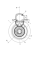
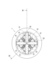
- FIG. 1 is an elevational view of a differential device according to one embodiment.
- FIG. 2 is a side view of the differential device.
- FIG. 3 is a cross-sectional side view of the differential device taken from line III--III in FIG.
- FIG. 4 is a cross-sectional view of the differential device taken along line IV--IV in FIG.
- FIG. 5 is a cross-sectional partial elevational view of the differential device, particularly showing its actuator and its surroundings.
- FIG. 6 is an elevational view of a differential device according to another embodiment.
- FIG. 7 is a sectional view of a differential device according to another embodiment, and corresponds to FIG. 4.
- FIG. 8 is a sectional view of a differential device according to yet another embodiment, and corresponds to FIGS. 4 and 7.
- FIG. 9 is
- axis refers to the axis of rotation of the differential device. Such a rotational axis usually also coincides with the rotational axis of the axle or cam mechanism, but this is not essential. Further, for convenience of explanation, right and left are sometimes distinguished, but of course embodiments in which the left and right are reversed are possible. It is particularly noted that the drawings are not necessarily drawn to scale and therefore the mutual dimensional relationships are not limited to those shown.
- bevel gear type differential device An example of a bevel gear type differential device will be described below, but it goes without saying that it may be based on other types such as a face gear type.
- a differential device can be used to differentially distribute torque about axis X to left and right axles.
- the differential device generally includes a casing 1 rotatable around an axis
- the friction clutch 5 includes a cam mechanism 7 disposed on the opposite side to the cam mechanism 7 for driving the cam mechanism 7, and a transmission member 9 for transmitting thrust force from the cam mechanism 7 to the friction clutch 5.
- a motor 61 connected to the carrier is connected to the cam mechanism 7 from the outside via a reduction gear set 63 to operate the cam mechanism 7, thereby exerting a thrust force on the friction clutch 5.
- the motor 61 can also be arranged coaxially with the differential device.
- the casing 1 includes a first wall 11 extending in the radial direction substantially perpendicular to the axis X at the left end thereof, a second wall 13 at the right end opposite thereto, and a wall 11 and 13. These walls 11, 13, 15 define a chamber, and this chamber accommodates the gear set 3 and the friction clutch 5.
- a boss 21 projects in the axial direction from the first wall 11, and a boss 23 projects in the axial direction from the second wall 13, and are supported by bearings of the carrier, so that the entire casing 1 is aligned with the axis X. Can be rotated around.
- the casing 1 can be connected to a ring gear, which is not depicted in FIG.
- the differential gear set 3 is a mechanism that differentially distributes torque around the axis X to the left and right axles.
- the differential gear set 3 includes, for example, one or more pinion shafts 35, pinion gears 37 rotatably supported by the pinion shafts 35, and gears meshing with the pinion gears 37, respectively.
- a first side gear 31 and a second side gear 33 are provided.
- the pinion shafts 35 may each be short round bars extending in the radial direction, and may be combined to form a cross as shown in the figure. Each outer end is connected to the peripheral wall 15 and thus receives torque from the casing 1.
- the connection can be, for example, by a so-called C-ring, as shown in FIG. 1, or by other fastening means, such as pins.
- a so-called spider may be used in which the inner ends of pinion shafts 35 are connected to each other by a ring-shaped member, as illustrated in FIG.
- the outer end of the pinion shaft 35 may not be coupled to the peripheral wall 15, but may be engaged with another element (the cage-shaped transmission member 9 in the example of FIG. 8), and may receive torque via it.
- the first side gear 31 faces the first wall 11
- the second side gear 33 faces the second wall 13, and each axle shaft join to.
- each side gear 31, 33 is provided with a spline or the like on its inner periphery.
- the side gears 31 and 33 can both receive torque and can be differentially moved with respect to each other. Therefore, the differential gear set 3 differentially distributes the received torque to the side gears 31 and 33.
- the friction clutch 5 is disposed between the first side gear 31 and the first wall 11, and exerts braking force in response to thrust force.
- the illustrated example is a multi-plate clutch, other types of friction clutches may of course be used.
- each of the friction clutches 5 has a substantially disk shape and is composed of outer plates and inner plates stacked alternately.
- the outer plate may be provided with radially outwardly projecting tabs and the inner plate may be provided with inwardly projecting lugs, correspondingly the casing 1 may have tab grooves and the first side gear 31 may have lugs.
- a groove may also be provided.
- the cam mechanism 7 has a structure that converts the rotational force of the motor 61 into axial thrust force.
- One example is a combination of a drive plate 71, a thrust plate 73 opposing the drive plate 71, and a cam structure interposed therebetween, which is shown in FIG. 5 in combination with FIG.
- the cam structure includes, for example, a slope provided on one or both of the plates 71 and 73, and a cam ball 75 that can roll on the slope.
- a roller may be used instead of the cam ball, or one slope may slide directly onto the other protrusion to push each other away without using a cam ball or the like.
- the drive plate 71 is rotatable around the axis X, but is fixed in the axial direction.
- a bearing 77 may be interposed between the second boss 23 and the drive plate 71 to rotatably support the drive plate 71.
- the drive plate 71 is provided with gear teeth on at least a portion of its periphery for meshing with the reduction gear set 63, and is therefore driven by the motor 61 via the reduction gear set 63.
- the thrust plate 73 is prevented from rotating around the axis X, but is movable in the axial direction.
- the carrier or other fastening element can be provided with an engaging part 41. The engaging portion 41 engages with the thrust plate 73 to prevent it from rotating.
- the cam mechanism 7 is arranged outside the casing 1 and adjacent to the second wall 13, as best shown in FIGS. It can directly exert thrust force.
- the transmission member 9 can have a correspondingly flat annular shape at least in the portion facing the thrust plate 73 . Since the transmission member 9 rotates together with the casing 1, a thrust bearing 79 is preferably interposed between the thrust plate 73 and the transmission member 9. Alternatively, it may slide directly or indirectly without a thrust bearing.
- the drive plate 71 is rotated by the motor 61, the thrust plate 73 is driven in the axial direction by the intervening cam structure, thereby applying a thrust force to the transmission member 9.
- the transmission member 9 further integrates a plurality of plungers 91 extending parallel to the axis X to transmit thrust force to the friction clutch 5 from the right end to the left end of the casing 1. , or as a separate item.
- An opening 17 is formed in the second wall 13 to correspond to the plunger 91 so as to pass therethrough, and the plunger 91 faces the cam mechanism 7 through the opening 17.
- the casing 1 may also be provided with grooves or cavities 19, for example on the inner surface of the peripheral wall 15, corresponding to the plungers 91, in which the plungers 91 are guided in each groove or cavity 19 and remain parallel to the axis X.
- each plunger 91 passes between the pinion gears 37 and extends from the second wall 13 side to the first wall 11 side.
- the plurality of plungers 91 are arranged symmetrically about axis X. This is advantageous in transmitting the thrust force evenly around the axis.
- the transmission member 9 may also include a pressing member 93 continuous in the circumferential direction at the end of the plunger 91 on the friction clutch 5 side, integrally or separately therewith.
- the pressing member 93 can make surface contact with the friction clutch 5, and can therefore apply thrust force to the friction clutch 5 symmetrically around the axis.
- the entire transmission member 9 may be in the form of a cage that encloses the differential gear set 3, as illustrated in FIG.
- the transmission member 9 on the side facing the friction clutch 5, the transmission member 9 has the form of a deep bowl that receives the first side gear 31, and a plurality of plungers 91 may branch and extend from the edge thereof.
- Each plunger 91 may extend between the pinion shafts 35 and toward the second wall 13 .
- the plurality of plungers 91 may be arranged symmetrically around the axis X.
- the inner surface of the peripheral wall 15 is provided with a groove 19 that engages with the transmission member 9, and the plurality of plungers 91 abut against the side surface of the pinion shaft 35, so that the transmission member 9 is moved from the casing 1 to the pinion shaft 35. It can also be responsible for transmitting torque to. In this case as well, the transmission member 9 is responsible for transmitting the thrust force from the cam mechanism 7 to the friction clutch 5, as in the example described above.
- the motor 61 can be arranged coaxially with the differential device, as in the examples shown in FIGS. 6 to 8.
- the motor 61 and the cam mechanism 7 may constitute an integrated actuator.
- the whole is housed and integrated in a housing 83 and supported on the boss 23.
- the entire actuator is rotatable relative to the boss 23, but is prevented from rotating relative to the carrier.
- the reaction force of the thrust force exerted by the C-ring is borne.
- the motor 61 generally consists of a rotor 65 and a stator 67 facing them across a gap G, as in the prior art.
- it may be a so-called radial gap motor in which the gap G is maintained in the radial direction
- the illustrated example is an axial gap motor in which the gap G is maintained in the axial direction.
- Both the rotor 65 and the stator 67 can be arranged coaxially with the axis X, but the stator 67 is prevented from rotating by, for example, the housing 83, and the rotor 65 is rotatable relative to them.
- a bearing such as a ball bearing 85, may be utilized for rotatable support, and may be interposed, for example, between rotor 65 and stator 67.
- the plurality of coils arranged in the circumferential direction generate magnetic flux according to the applied electric power, and the magnetic flux jumping across the gap G drives the rotor 65 to rotate it around the axis X.
- Rotor 65 is also coupled to and drives cam mechanism 7.
- the cam mechanism 7 may include a drive plate 71, a thrust plate 73, and a cam ball 75 interposed between them, as in the example shown in FIG. 5 described above.
- a mechanism using planetary gears may be used, as in the examples shown in FIGS. 9 and 10.
- the drive plate 71 and the thrust plate 73 are internal gears having internal teeth 71t and 73t, respectively, and are both rotatable around the axis X, unlike the example shown in FIG.
- a plurality of planetary gears 81 mesh with these inner peripheries.
- planetary gear 81 is arranged symmetrically with respect to axis X.
- a sun gear portion 67t provided with external teeth and prevented from rotating is disposed inside the planetary gear 81 in the radial direction, and meshes with the sun gear portion 67t.
- the sun gear portion 67t extends integrally from the stator 67, but this is not essential, and may be fixed to the housing 83, for example.
- the internal teeth 71t of the drive plate 71 and the internal teeth 73t of the thrust plate 73 have slightly different numbers of teeth. Therefore, when the drive plate 71 is rotated by the motor 61, the gap between the drive plate 71 and the thrust plate 73 is A rotation difference occurs. Using this difference in rotation, the cam ball 75 pushes up the thrust plate 73, thereby converting the rotational force into a thrust force.
- any suitable cam structure may be used without the cam ball.
- the degree of boost by the cam mechanism 7 is usually larger than that by the reduction gear, and can be adjusted as appropriate by the difference in the number of teeth. That is, the actuator according to this embodiment can controllably exert a particularly large thrust force compared to the conventional technology. Similar to the example of FIG. 5 already described, in this embodiment as well, the thrust plate 73 is adjacent to the transmission member 9, and the friction clutch 5 can be operated via this. The actuator according to this embodiment can also be used for other purposes.
- the friction clutch near the left end and the cam mechanism near the right end are approximately the same size, and the differential device has a generally symmetrical structure.
- the left and right axles can therefore be of equal length, similar to a differential without a limited slip differential.
- it is not particularly large compared to a differential device without a differential limiting device, and therefore, the differential device according to this embodiment can be used interchangeably with this differential device.
Landscapes
- Engineering & Computer Science (AREA)
- General Engineering & Computer Science (AREA)
- Mechanical Engineering (AREA)
- Retarders (AREA)
Priority Applications (5)
| Application Number | Priority Date | Filing Date | Title |
|---|---|---|---|
| CN202280096963.9A CN119343551A (zh) | 2022-08-05 | 2022-08-05 | 差速器装置 |
| PCT/JP2022/030149 WO2024029081A1 (ja) | 2022-08-05 | 2022-08-05 | デファレンシャル装置 |
| JP2024538795A JPWO2024029081A1 (https=) | 2022-08-05 | 2022-08-05 | |
| DE112022007628.3T DE112022007628T5 (de) | 2022-08-05 | 2022-08-05 | Differentialvorrichtung |
| US18/958,210 US20250084917A1 (en) | 2022-08-05 | 2024-11-25 | Differential device |
Applications Claiming Priority (1)
| Application Number | Priority Date | Filing Date | Title |
|---|---|---|---|
| PCT/JP2022/030149 WO2024029081A1 (ja) | 2022-08-05 | 2022-08-05 | デファレンシャル装置 |
Related Child Applications (1)
| Application Number | Title | Priority Date | Filing Date |
|---|---|---|---|
| US18/958,210 Continuation US20250084917A1 (en) | 2022-08-05 | 2024-11-25 | Differential device |
Publications (1)
| Publication Number | Publication Date |
|---|---|
| WO2024029081A1 true WO2024029081A1 (ja) | 2024-02-08 |
Family
ID=89848949
Family Applications (1)
| Application Number | Title | Priority Date | Filing Date |
|---|---|---|---|
| PCT/JP2022/030149 Ceased WO2024029081A1 (ja) | 2022-08-05 | 2022-08-05 | デファレンシャル装置 |
Country Status (5)
| Country | Link |
|---|---|
| US (1) | US20250084917A1 (https=) |
| JP (1) | JPWO2024029081A1 (https=) |
| CN (1) | CN119343551A (https=) |
| DE (1) | DE112022007628T5 (https=) |
| WO (1) | WO2024029081A1 (https=) |
Citations (2)
| Publication number | Priority date | Publication date | Assignee | Title |
|---|---|---|---|---|
| JP2005249080A (ja) * | 2004-03-04 | 2005-09-15 | Honda Motor Co Ltd | 差動制限機構付き差動装置 |
| JP2008309337A (ja) * | 2008-09-16 | 2008-12-25 | Gkn ドライブライン トルクテクノロジー株式会社 | 摩擦クラッチの締結機構および該機構を備えるディファレンシャル装置 |
Family Cites Families (6)
| Publication number | Priority date | Publication date | Assignee | Title |
|---|---|---|---|---|
| US4838118A (en) * | 1988-03-10 | 1989-06-13 | Eaton Corporation | Anti-spin differential |
| JPH0221354U (https=) * | 1988-07-28 | 1990-02-13 | ||
| US6537172B1 (en) * | 2001-10-18 | 2003-03-25 | Eaton Corporation | Electronically actuated modulatable differential |
| US6796412B2 (en) * | 2001-12-27 | 2004-09-28 | Tochigi Fuji Sangyo Kabushiki Kaisha | Differential apparatus |
| US6623394B2 (en) * | 2001-12-28 | 2003-09-23 | Visteon Global Technologies, Inc. | Eddy current activation of a limited slip differential system |
| US11221065B2 (en) * | 2020-05-06 | 2022-01-11 | American Axle & Manufacturing, Inc. | Vehicle driveline component having differential assembly with integrated electronically-controlled limited slip and locking functionality |
-
2022
- 2022-08-05 JP JP2024538795A patent/JPWO2024029081A1/ja active Pending
- 2022-08-05 CN CN202280096963.9A patent/CN119343551A/zh active Pending
- 2022-08-05 WO PCT/JP2022/030149 patent/WO2024029081A1/ja not_active Ceased
- 2022-08-05 DE DE112022007628.3T patent/DE112022007628T5/de active Pending
-
2024
- 2024-11-25 US US18/958,210 patent/US20250084917A1/en active Pending
Patent Citations (2)
| Publication number | Priority date | Publication date | Assignee | Title |
|---|---|---|---|---|
| JP2005249080A (ja) * | 2004-03-04 | 2005-09-15 | Honda Motor Co Ltd | 差動制限機構付き差動装置 |
| JP2008309337A (ja) * | 2008-09-16 | 2008-12-25 | Gkn ドライブライン トルクテクノロジー株式会社 | 摩擦クラッチの締結機構および該機構を備えるディファレンシャル装置 |
Also Published As
| Publication number | Publication date |
|---|---|
| DE112022007628T5 (de) | 2025-05-28 |
| US20250084917A1 (en) | 2025-03-13 |
| CN119343551A (zh) | 2025-01-21 |
| JPWO2024029081A1 (https=) | 2024-02-08 |
Similar Documents
| Publication | Publication Date | Title |
|---|---|---|
| CN107917175B (zh) | 用于车辆的差动限制装置 | |
| JP2636229B2 (ja) | 四輪駆動用中央差動装置の差動制限機構 | |
| US11174928B2 (en) | Differential device with two-step ability to limit differential motion | |
| US8251849B2 (en) | Clutching method and mechanism for electrically variable transmissions | |
| KR101807884B1 (ko) | 정면 기어와 피니언 하우징을 사용하는 차동 제한 장치 | |
| WO2015068821A1 (ja) | 動力伝達装置 | |
| CN108474454B (zh) | 组合有行星齿轮机构的旋转传递装置 | |
| JP2003184993A (ja) | ディファレンシャル・アセンブリにおけるクラッチ・アクチュエータ用のギヤ・モジュール | |
| US5217416A (en) | Lock up/limited slip differential | |
| US7998011B2 (en) | Speed change apparatus | |
| CN103233987B (zh) | 扭矩传递系统 | |
| WO2024029081A1 (ja) | デファレンシャル装置 | |
| JP7457186B2 (ja) | カップリング装置 | |
| KR102519195B1 (ko) | 자동차용 슬립 제한형 차동 장치 및 이를 포함하는 전동 구동 장치 | |
| WO2017042882A1 (ja) | リミテッドスリップデフ | |
| JP2009085293A (ja) | 差動制限装置 | |
| US12372146B1 (en) | Sub-assembly for e-axle | |
| US20130157800A1 (en) | Limited Slip Planetary Gear Transmission | |
| WO2025220730A1 (ja) | 2段変速機および電気自動車駆動装置 | |
| JP2022175336A (ja) | 変速装置 | |
| JPH04132243U (ja) | 差動制限装置 | |
| JP3300393B2 (ja) | 四輪駆動車用駆動力伝達装置 | |
| JPS63184525A (ja) | 差動制限装置 | |
| JPH084885A (ja) | デフケース及びそのデフケースを用いたデファレンシャル装置 | |
| JP2012189203A (ja) | 駆動力伝達装置 |
Legal Events
| Date | Code | Title | Description |
|---|---|---|---|
| 121 | Ep: the epo has been informed by wipo that ep was designated in this application |
Ref document number: 22954069 Country of ref document: EP Kind code of ref document: A1 |
|
| WWE | Wipo information: entry into national phase |
Ref document number: 2024538795 Country of ref document: JP |
|
| WWE | Wipo information: entry into national phase |
Ref document number: 202280096963.9 Country of ref document: CN |
|
| WWP | Wipo information: published in national office |
Ref document number: 202280096963.9 Country of ref document: CN |
|
| WWE | Wipo information: entry into national phase |
Ref document number: 112022007628 Country of ref document: DE |
|
| WWP | Wipo information: published in national office |
Ref document number: 112022007628 Country of ref document: DE |
|
| 122 | Ep: pct application non-entry in european phase |
Ref document number: 22954069 Country of ref document: EP Kind code of ref document: A1 |