WO2024029081A1 - Differential device - Google Patents
Differential device Download PDFInfo
- Publication number
- WO2024029081A1 WO2024029081A1 PCT/JP2022/030149 JP2022030149W WO2024029081A1 WO 2024029081 A1 WO2024029081 A1 WO 2024029081A1 JP 2022030149 W JP2022030149 W JP 2022030149W WO 2024029081 A1 WO2024029081 A1 WO 2024029081A1
- Authority
- WO
- WIPO (PCT)
- Prior art keywords
- wall
- side gear
- axis
- differential device
- pinion
- Prior art date
Links
- 230000007246 mechanism Effects 0.000 claims abstract description 26
- 230000005540 biological transmission Effects 0.000 claims abstract description 20
- 230000002093 peripheral effect Effects 0.000 claims abstract description 11
- 230000009467 reduction Effects 0.000 description 4
- 230000004907 flux Effects 0.000 description 2
- 241000239290 Araneae Species 0.000 description 1
- 230000008859 change Effects 0.000 description 1
- 230000003247 decreasing effect Effects 0.000 description 1
- 230000009191 jumping Effects 0.000 description 1
- 230000004044 response Effects 0.000 description 1
Images


Classifications
-
- F—MECHANICAL ENGINEERING; LIGHTING; HEATING; WEAPONS; BLASTING
- F16—ENGINEERING ELEMENTS AND UNITS; GENERAL MEASURES FOR PRODUCING AND MAINTAINING EFFECTIVE FUNCTIONING OF MACHINES OR INSTALLATIONS; THERMAL INSULATION IN GENERAL
- F16H—GEARING
- F16H48/00—Differential gearings
- F16H48/20—Arrangements for suppressing or influencing the differential action, e.g. locking devices
- F16H48/22—Arrangements for suppressing or influencing the differential action, e.g. locking devices using friction clutches or brakes
Definitions
- the following disclosure relates to an electronically controlled limited slip differential (LSD) device convenient for differentially outputting torque to axles of equal length.
- LSD electronically controlled limited slip differential
- a differential device is used to transmit torque to both axles while allowing differential movement.
- the multi-disc clutch is adjacent to the side gear, and the actuator that applies pressing force to it needs to be installed further adjacent to the multi-disc clutch.
- the multi-disc clutch and actuator are necessarily installed to the side of the differential device. Therefore, it is not possible to make both axles of equal length, or if both axles are made of equal length, the differential device must be disposed biased to either the left or right side of the vehicle. Such an arrangement causes disadvantages such as differences in characteristics between the two axles and, by extension, between the two wheels.
- the differential device disclosed below provides a means to solve this problem.
- a differential device for outputting torque about an axis includes a first wall extending radially at a first end with respect to the axis and a second wall extending radially at a second end with respect to the axis.
- a casing comprising: a wall; a peripheral wall connecting the first wall and the second wall; the first wall, the second wall, and the peripheral wall define a chamber; a first side gear that is housed in and faces the first wall, a second side gear that faces the second wall, and a plurality of pinion shafts that extend in a radial direction, each of which is rotatable to the pinion shaft; a plurality of pinion gears supported and meshed with the first side gear and the second side gear; a friction clutch disposed between the first side gear and the first wall to brake the first side gear against the first wall; a cam mechanism disposed coaxially with the shaft adjacent to the second wall and converting a rotational force about the shaft into a thrust force in the direction of the shaft;
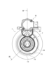
- FIG. 1 is an elevational view of a differential device according to one embodiment.
- FIG. 2 is a side view of the differential device.
- FIG. 3 is a cross-sectional side view of the differential device taken from line III--III in FIG.
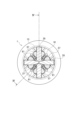
- FIG. 4 is a cross-sectional view of the differential device taken along line IV--IV in FIG.
- FIG. 5 is a cross-sectional partial elevational view of the differential device, particularly showing its actuator and its surroundings.
- FIG. 6 is an elevational view of a differential device according to another embodiment.
- FIG. 7 is a sectional view of a differential device according to another embodiment, and corresponds to FIG. 4.
- FIG. 8 is a sectional view of a differential device according to yet another embodiment, and corresponds to FIGS. 4 and 7.
- FIG. 9 is
- axis refers to the axis of rotation of the differential device. Such a rotational axis usually also coincides with the rotational axis of the axle or cam mechanism, but this is not essential. Further, for convenience of explanation, right and left are sometimes distinguished, but of course embodiments in which the left and right are reversed are possible. It is particularly noted that the drawings are not necessarily drawn to scale and therefore the mutual dimensional relationships are not limited to those shown.
- bevel gear type differential device An example of a bevel gear type differential device will be described below, but it goes without saying that it may be based on other types such as a face gear type.
- a differential device can be used to differentially distribute torque about axis X to left and right axles.
- the differential device generally includes a casing 1 rotatable around an axis
- the friction clutch 5 includes a cam mechanism 7 disposed on the opposite side to the cam mechanism 7 for driving the cam mechanism 7, and a transmission member 9 for transmitting thrust force from the cam mechanism 7 to the friction clutch 5.
- a motor 61 connected to the carrier is connected to the cam mechanism 7 from the outside via a reduction gear set 63 to operate the cam mechanism 7, thereby exerting a thrust force on the friction clutch 5.
- the motor 61 can also be arranged coaxially with the differential device.
- the casing 1 includes a first wall 11 extending in the radial direction substantially perpendicular to the axis X at the left end thereof, a second wall 13 at the right end opposite thereto, and a wall 11 and 13. These walls 11, 13, 15 define a chamber, and this chamber accommodates the gear set 3 and the friction clutch 5.
- a boss 21 projects in the axial direction from the first wall 11, and a boss 23 projects in the axial direction from the second wall 13, and are supported by bearings of the carrier, so that the entire casing 1 is aligned with the axis X. Can be rotated around.
- the casing 1 can be connected to a ring gear, which is not depicted in FIG.
- the differential gear set 3 is a mechanism that differentially distributes torque around the axis X to the left and right axles.
- the differential gear set 3 includes, for example, one or more pinion shafts 35, pinion gears 37 rotatably supported by the pinion shafts 35, and gears meshing with the pinion gears 37, respectively.
- a first side gear 31 and a second side gear 33 are provided.
- the pinion shafts 35 may each be short round bars extending in the radial direction, and may be combined to form a cross as shown in the figure. Each outer end is connected to the peripheral wall 15 and thus receives torque from the casing 1.
- the connection can be, for example, by a so-called C-ring, as shown in FIG. 1, or by other fastening means, such as pins.
- a so-called spider may be used in which the inner ends of pinion shafts 35 are connected to each other by a ring-shaped member, as illustrated in FIG.
- the outer end of the pinion shaft 35 may not be coupled to the peripheral wall 15, but may be engaged with another element (the cage-shaped transmission member 9 in the example of FIG. 8), and may receive torque via it.
- the first side gear 31 faces the first wall 11
- the second side gear 33 faces the second wall 13, and each axle shaft join to.
- each side gear 31, 33 is provided with a spline or the like on its inner periphery.
- the side gears 31 and 33 can both receive torque and can be differentially moved with respect to each other. Therefore, the differential gear set 3 differentially distributes the received torque to the side gears 31 and 33.
- the friction clutch 5 is disposed between the first side gear 31 and the first wall 11, and exerts braking force in response to thrust force.
- the illustrated example is a multi-plate clutch, other types of friction clutches may of course be used.
- each of the friction clutches 5 has a substantially disk shape and is composed of outer plates and inner plates stacked alternately.
- the outer plate may be provided with radially outwardly projecting tabs and the inner plate may be provided with inwardly projecting lugs, correspondingly the casing 1 may have tab grooves and the first side gear 31 may have lugs.
- a groove may also be provided.
- the cam mechanism 7 has a structure that converts the rotational force of the motor 61 into axial thrust force.
- One example is a combination of a drive plate 71, a thrust plate 73 opposing the drive plate 71, and a cam structure interposed therebetween, which is shown in FIG. 5 in combination with FIG.
- the cam structure includes, for example, a slope provided on one or both of the plates 71 and 73, and a cam ball 75 that can roll on the slope.
- a roller may be used instead of the cam ball, or one slope may slide directly onto the other protrusion to push each other away without using a cam ball or the like.
- the drive plate 71 is rotatable around the axis X, but is fixed in the axial direction.
- a bearing 77 may be interposed between the second boss 23 and the drive plate 71 to rotatably support the drive plate 71.
- the drive plate 71 is provided with gear teeth on at least a portion of its periphery for meshing with the reduction gear set 63, and is therefore driven by the motor 61 via the reduction gear set 63.
- the thrust plate 73 is prevented from rotating around the axis X, but is movable in the axial direction.
- the carrier or other fastening element can be provided with an engaging part 41. The engaging portion 41 engages with the thrust plate 73 to prevent it from rotating.
- the cam mechanism 7 is arranged outside the casing 1 and adjacent to the second wall 13, as best shown in FIGS. It can directly exert thrust force.
- the transmission member 9 can have a correspondingly flat annular shape at least in the portion facing the thrust plate 73 . Since the transmission member 9 rotates together with the casing 1, a thrust bearing 79 is preferably interposed between the thrust plate 73 and the transmission member 9. Alternatively, it may slide directly or indirectly without a thrust bearing.
- the drive plate 71 is rotated by the motor 61, the thrust plate 73 is driven in the axial direction by the intervening cam structure, thereby applying a thrust force to the transmission member 9.
- the transmission member 9 further integrates a plurality of plungers 91 extending parallel to the axis X to transmit thrust force to the friction clutch 5 from the right end to the left end of the casing 1. , or as a separate item.
- An opening 17 is formed in the second wall 13 to correspond to the plunger 91 so as to pass therethrough, and the plunger 91 faces the cam mechanism 7 through the opening 17.
- the casing 1 may also be provided with grooves or cavities 19, for example on the inner surface of the peripheral wall 15, corresponding to the plungers 91, in which the plungers 91 are guided in each groove or cavity 19 and remain parallel to the axis X.
- each plunger 91 passes between the pinion gears 37 and extends from the second wall 13 side to the first wall 11 side.
- the plurality of plungers 91 are arranged symmetrically about axis X. This is advantageous in transmitting the thrust force evenly around the axis.
- the transmission member 9 may also include a pressing member 93 continuous in the circumferential direction at the end of the plunger 91 on the friction clutch 5 side, integrally or separately therewith.
- the pressing member 93 can make surface contact with the friction clutch 5, and can therefore apply thrust force to the friction clutch 5 symmetrically around the axis.
- the entire transmission member 9 may be in the form of a cage that encloses the differential gear set 3, as illustrated in FIG.
- the transmission member 9 on the side facing the friction clutch 5, the transmission member 9 has the form of a deep bowl that receives the first side gear 31, and a plurality of plungers 91 may branch and extend from the edge thereof.
- Each plunger 91 may extend between the pinion shafts 35 and toward the second wall 13 .
- the plurality of plungers 91 may be arranged symmetrically around the axis X.
- the inner surface of the peripheral wall 15 is provided with a groove 19 that engages with the transmission member 9, and the plurality of plungers 91 abut against the side surface of the pinion shaft 35, so that the transmission member 9 is moved from the casing 1 to the pinion shaft 35. It can also be responsible for transmitting torque to. In this case as well, the transmission member 9 is responsible for transmitting the thrust force from the cam mechanism 7 to the friction clutch 5, as in the example described above.
- the motor 61 can be arranged coaxially with the differential device, as in the examples shown in FIGS. 6 to 8.
- the motor 61 and the cam mechanism 7 may constitute an integrated actuator.
- the whole is housed and integrated in a housing 83 and supported on the boss 23.
- the entire actuator is rotatable relative to the boss 23, but is prevented from rotating relative to the carrier.
- the reaction force of the thrust force exerted by the C-ring is borne.
- the motor 61 generally consists of a rotor 65 and a stator 67 facing them across a gap G, as in the prior art.
- it may be a so-called radial gap motor in which the gap G is maintained in the radial direction
- the illustrated example is an axial gap motor in which the gap G is maintained in the axial direction.
- Both the rotor 65 and the stator 67 can be arranged coaxially with the axis X, but the stator 67 is prevented from rotating by, for example, the housing 83, and the rotor 65 is rotatable relative to them.
- a bearing such as a ball bearing 85, may be utilized for rotatable support, and may be interposed, for example, between rotor 65 and stator 67.
- the plurality of coils arranged in the circumferential direction generate magnetic flux according to the applied electric power, and the magnetic flux jumping across the gap G drives the rotor 65 to rotate it around the axis X.
- Rotor 65 is also coupled to and drives cam mechanism 7.
- the cam mechanism 7 may include a drive plate 71, a thrust plate 73, and a cam ball 75 interposed between them, as in the example shown in FIG. 5 described above.
- a mechanism using planetary gears may be used, as in the examples shown in FIGS. 9 and 10.
- the drive plate 71 and the thrust plate 73 are internal gears having internal teeth 71t and 73t, respectively, and are both rotatable around the axis X, unlike the example shown in FIG.
- a plurality of planetary gears 81 mesh with these inner peripheries.
- planetary gear 81 is arranged symmetrically with respect to axis X.
- a sun gear portion 67t provided with external teeth and prevented from rotating is disposed inside the planetary gear 81 in the radial direction, and meshes with the sun gear portion 67t.
- the sun gear portion 67t extends integrally from the stator 67, but this is not essential, and may be fixed to the housing 83, for example.
- the internal teeth 71t of the drive plate 71 and the internal teeth 73t of the thrust plate 73 have slightly different numbers of teeth. Therefore, when the drive plate 71 is rotated by the motor 61, the gap between the drive plate 71 and the thrust plate 73 is A rotation difference occurs. Using this difference in rotation, the cam ball 75 pushes up the thrust plate 73, thereby converting the rotational force into a thrust force.
- any suitable cam structure may be used without the cam ball.
- the degree of boost by the cam mechanism 7 is usually larger than that by the reduction gear, and can be adjusted as appropriate by the difference in the number of teeth. That is, the actuator according to this embodiment can controllably exert a particularly large thrust force compared to the conventional technology. Similar to the example of FIG. 5 already described, in this embodiment as well, the thrust plate 73 is adjacent to the transmission member 9, and the friction clutch 5 can be operated via this. The actuator according to this embodiment can also be used for other purposes.
- the friction clutch near the left end and the cam mechanism near the right end are approximately the same size, and the differential device has a generally symmetrical structure.
- the left and right axles can therefore be of equal length, similar to a differential without a limited slip differential.
- it is not particularly large compared to a differential device without a differential limiting device, and therefore, the differential device according to this embodiment can be used interchangeably with this differential device.
Abstract
A differential device for outputting torque around an axis is provided, comprising: a casing comprising a first wall extending in a radial direction at a first end with respect to the axis, a second wall extending in the radial direction at a second end with respect to the axis, and a peripheral wall communicating the first wall and the second wall, the first wall, the second wall, and the peripheral wall defining a chamber; a differential gear set that comprises a first side gear housed in the chamber and facing the first wall, a second side gear facing the second wall, a plurality of pinion shafts extending in the radial direction, and a plurality of pinion gears that are rotatably supported by the pinion shafts, respectively, and are meshed with the first side gear and the second side gear, the differential gear set differentially distributing the torque received by the pinion shafts to the first side gear and the second side gear; a friction clutch that is disposed between the first side gear and the first wall, and brakes the first side gear with respect to the first wall; a cam mechanism that is disposed outside the casing adjacent to the second wall and coaxially with the axis, and that converts a rotating force around the axis into a thrust force in the direction of the axis; and a transmission member that includes a plurality of plungers each extending between the plurality of pinion gears or the plurality of pinion shafts in parallel to the axis, and being capable of transmitting the thrust force, the transmission member contacting the friction clutch to apply the thrust force thereto.
Description
以下の開示は、等長の車軸に差動的にトルクを出力するのに都合のよい電子制御リミテッドスリップデファレンシャル(LSD)装置に関する。
The following disclosure relates to an electronically controlled limited slip differential (LSD) device convenient for differentially outputting torque to axles of equal length.
自動車において、左右の車軸は必ずしも等速で回転するわけではないので、その間の差動を許容する必要がある。差動を許容しながら両車軸へトルクを伝達するために、デファレンシャル装置が利用される。
In automobiles, the left and right axles do not necessarily rotate at the same speed, so it is necessary to allow for differential movement between them. A differential device is used to transmit torque to both axles while allowing differential movement.
左右の駆動輪の何れかがトラクションを失ったときにはデファレンシャル装置は空転してしまい、他方の駆動輪にもトルクを伝えることができなくなる。かかる事態を回避するために、幾つかのデファレンシャル装置は差動を制限する機構を備える。その一例は、多板クラッチを利用した電子制御式のリミテッドスリップデフ(LSD)である。電子制御の下に多板クラッチに印加する押圧力を増減すれば、それに応じて差動の制限の程度が変化し、さらに十分な押圧力を印加すれば多板クラッチは滑らなくなるので、いわゆるデファレンシャルロックも可能である。特許文献1は、関連する技術を開示する。
When either of the left or right drive wheels loses traction, the differential gear spins idly, making it impossible to transmit torque to the other drive wheel. To avoid such a situation, some differential devices are equipped with a mechanism to limit differential movement. One example is an electronically controlled limited slip differential (LSD) that uses a multi-plate clutch. If the pressing force applied to the multi-disc clutch is increased or decreased under electronic control, the degree of restriction of the differential will change accordingly, and if sufficient pressing force is applied, the multi-disc clutch will not slip, so the so-called differential Locking is also possible. Patent Document 1 discloses related technology.
多板クラッチはサイドギアに隣接し、これに押圧力を印加するアクチュエータはさらに多板クラッチに隣接して設置する必要がある。多板クラッチおよびアクチュエータは必然的にデファレンシャル装置の側方に偏って設置される。すると両車軸を等長にすることができず、あるいは両車軸を等長とすればデファレンシャル装置は車両において左右の何れかに偏って配置せざるをえない。そのような配置は、両車軸の間で、ひいては両車輪の間で特性に相違が出るなどの不都合を生じる。以下に開示するデファレンシャル装置は、かかる問題を解決する手段を提供する。
The multi-disc clutch is adjacent to the side gear, and the actuator that applies pressing force to it needs to be installed further adjacent to the multi-disc clutch. The multi-disc clutch and actuator are necessarily installed to the side of the differential device. Therefore, it is not possible to make both axles of equal length, or if both axles are made of equal length, the differential device must be disposed biased to either the left or right side of the vehicle. Such an arrangement causes disadvantages such as differences in characteristics between the two axles and, by extension, between the two wheels. The differential device disclosed below provides a means to solve this problem.
一局面によれば、軸の周りのトルクを出力するデファレンシャル装置は、前記軸に関して第1の端において径方向に延びる第1の壁と、前記軸に関して第2の端において径方向に延びる第2の壁と、前記第1の壁と前記第2の壁とを連絡する周壁と、を備え、前記第1の壁と前記第2の壁と前記周壁とが室を画するケーシングと、前記室に収容され、前記第1の壁に面した第1のサイドギアと、前記第2の壁に面した第2のサイドギアと、径方向に延びる複数のピニオンシャフトと、それぞれ前記ピニオンシャフトに回転可能に支持されて前記第1のサイドギアおよび前記第2のサイドギアに噛合した複数のピニオンギアと、を備え、前記ピニオンシャフトが受容した前記トルクを前記第1のサイドギアおよび前記第2のサイドギアへ差動的に分配するデファレンシャルギア組と、前記第1のサイドギアと前記第1の壁との間に配置されて前記第1のサイドギアを前記第1の壁に対して制動する摩擦クラッチと、前記ケーシング外であって前記第2の壁に隣接して前記軸に同軸に配置され、前記軸の周りの回転力を前記軸の方向のスラスト力に変換するカム機構と、それぞれ前記複数のピニオンギアの間、または前記複数のピニオンシャフトの間を通って前記軸に平行に延び、前記スラスト力を伝達可能な複数のプランジャを含み、前記摩擦クラッチに接して前記スラスト力を印加する伝達部材と、を備える。
According to one aspect, a differential device for outputting torque about an axis includes a first wall extending radially at a first end with respect to the axis and a second wall extending radially at a second end with respect to the axis. a casing comprising: a wall; a peripheral wall connecting the first wall and the second wall; the first wall, the second wall, and the peripheral wall define a chamber; a first side gear that is housed in and faces the first wall, a second side gear that faces the second wall, and a plurality of pinion shafts that extend in a radial direction, each of which is rotatable to the pinion shaft; a plurality of pinion gears supported and meshed with the first side gear and the second side gear; a friction clutch disposed between the first side gear and the first wall to brake the first side gear against the first wall; a cam mechanism disposed coaxially with the shaft adjacent to the second wall and converting a rotational force about the shaft into a thrust force in the direction of the shaft; and a cam mechanism between each of the plurality of pinion gears; Alternatively, the transmission member includes a plurality of plungers that extend parallel to the axis and pass between the plurality of pinion shafts, are capable of transmitting the thrust force, and are in contact with the friction clutch to apply the thrust force.
添付の図面を参照して以下に幾つかの例示的な実施形態を説明する。以下の説明および請求の範囲を通じて、特段の説明がなければ、軸はデファレンシャル装置の回転軸の意味である。かかる回転軸は、通常には車軸やカム機構の回転軸とも一致するが、一致は必須ではない。また説明の便宜のために右と左を区別することがあるが、もちろん左右を反対にした実施形態が可能である。図面は必ずしも正確な縮尺により示されておらず、従って相互の寸法関係は図示されたものに限られないことに特に注意を要する。
Some exemplary embodiments will be described below with reference to the accompanying drawings. Throughout the following description and claims, unless otherwise specified, the term axis refers to the axis of rotation of the differential device. Such a rotational axis usually also coincides with the rotational axis of the axle or cam mechanism, but this is not essential. Further, for convenience of explanation, right and left are sometimes distinguished, but of course embodiments in which the left and right are reversed are possible. It is particularly noted that the drawings are not necessarily drawn to scale and therefore the mutual dimensional relationships are not limited to those shown.
ベベルギア式のデファレンシャル装置の例を以下に説明するが、言うまでもなくフェースギア式等の他の形式に基づいてもよい。
An example of a bevel gear type differential device will be described below, but it goes without saying that it may be based on other types such as a face gear type.
例えば図1ないし4を参照するに、デファレンシャル装置は、軸Xの周りのトルクを左右の車軸へ差動的に分配する用途に利用できる。デファレンシャル装置は、概して、軸Xの周りに回転可能なケーシング1と、ケーシング1に収容されたデファレンシャルギア組3と、デファレンシャルギア組3の差動を制限するための摩擦クラッチ5と、摩擦クラッチ5とは反対側に配置されてこれを駆動するためのカム機構7と、カム機構7から摩擦クラッチ5へスラスト力を伝達する伝達部材9と、を備える。図示の例では、キャリアに結合したモータ61が外部から減速ギア組63を介してカム機構7に結合することによりこれを動作させ、以って摩擦クラッチ5にスラスト力を及ぼす。ただし図6ないし8に示す各例の通り、モータ61はデファレンシャル装置と同軸に配置することもできる。
For example, with reference to FIGS. 1-4, a differential device can be used to differentially distribute torque about axis X to left and right axles. The differential device generally includes a casing 1 rotatable around an axis The friction clutch 5 includes a cam mechanism 7 disposed on the opposite side to the cam mechanism 7 for driving the cam mechanism 7, and a transmission member 9 for transmitting thrust force from the cam mechanism 7 to the friction clutch 5. In the illustrated example, a motor 61 connected to the carrier is connected to the cam mechanism 7 from the outside via a reduction gear set 63 to operate the cam mechanism 7, thereby exerting a thrust force on the friction clutch 5. However, as shown in each example shown in FIGS. 6 to 8, the motor 61 can also be arranged coaxially with the differential device.
主に図1に戻って参照するに、ケーシング1は、その左端において軸Xに略直交して径方向に延びる第1の壁11と、これに対向する右端の第2の壁13と、壁11,13を連絡する周壁15と、よりなり、これら壁11,13,15は室を画し、かかる室がギア組3および摩擦クラッチ5を収容する。第1の壁11からはボス21が軸方向に突出し、また第2の壁13からはボス23が軸方向に突出し、それぞれキャリアの軸受けに支持されることによって、ケーシング1の全体は軸Xの周りに回転可能である。エンジンないし駆動モータからトルクを受容するべく、ケーシング1はリングギアと結合することができるが、図1には描かれていない。
Mainly referring back to FIG. 1, the casing 1 includes a first wall 11 extending in the radial direction substantially perpendicular to the axis X at the left end thereof, a second wall 13 at the right end opposite thereto, and a wall 11 and 13. These walls 11, 13, 15 define a chamber, and this chamber accommodates the gear set 3 and the friction clutch 5. A boss 21 projects in the axial direction from the first wall 11, and a boss 23 projects in the axial direction from the second wall 13, and are supported by bearings of the carrier, so that the entire casing 1 is aligned with the axis X. Can be rotated around. In order to receive torque from an engine or a drive motor, the casing 1 can be connected to a ring gear, which is not depicted in FIG.
デファレンシャルギア組3は、軸Xの周りのトルクを左右の車軸に差動的に分配する機構である。主に図3,4を参照するに、デファレンシャルギア組3は、例えば一以上のピニオンシャフト35と、それぞれピニオンシャフト35に回転可能に支持されたピニオンギア37と、ピニオンギア37にそれぞれ噛合した第1のサイドギア31,第2のサイドギア33と、を備える。
The differential gear set 3 is a mechanism that differentially distributes torque around the axis X to the left and right axles. Mainly referring to FIGS. 3 and 4, the differential gear set 3 includes, for example, one or more pinion shafts 35, pinion gears 37 rotatably supported by the pinion shafts 35, and gears meshing with the pinion gears 37, respectively. A first side gear 31 and a second side gear 33 are provided.
ピニオンシャフト35はそれぞれ径方向に延びる短い丸棒であってもよく、図示の通り十字をなして組み合わせてもよい。それぞれの外端は周壁15に結合し、以ってケーシング1からトルクを受容する。結合は例えば図1に示す通り所謂Cリングによることができ、あるいはピン等の他の固定手段によることができる。あるいはかかる構造に代えて、図8に例示される通りピニオンシャフト35の内端がリング状の部材により互いに結合した所謂スパイダを利用してもよい。またピニオンシャフト35の外端は周壁15に結合せずに、他の要素(図8の例ではケージ状の伝達部材9)に係合し、それを介してトルクを受容してもよい。
The pinion shafts 35 may each be short round bars extending in the radial direction, and may be combined to form a cross as shown in the figure. Each outer end is connected to the peripheral wall 15 and thus receives torque from the casing 1. The connection can be, for example, by a so-called C-ring, as shown in FIG. 1, or by other fastening means, such as pins. Alternatively, instead of such a structure, a so-called spider may be used in which the inner ends of pinion shafts 35 are connected to each other by a ring-shaped member, as illustrated in FIG. Further, the outer end of the pinion shaft 35 may not be coupled to the peripheral wall 15, but may be engaged with another element (the cage-shaped transmission member 9 in the example of FIG. 8), and may receive torque via it.
図4,7,8の何れかを参照するに、第1のサイドギア31は第1の壁11に面しており、第2のサイドギア33は第2の壁13に面しており、それぞれ車軸に結合する。結合のために、各サイドギア31,33はその内周にスプライン等を備える。ピニオンシャフト35の周りにそれぞれ回転可能なピニオンギア37に噛合することにより、サイドギア31,33は共にトルクを受容し、また相互に差動が可能である。それゆえデファレンシャルギア組3は受容したトルクをサイドギア31,33に差動的に分配する。
4, 7, and 8, the first side gear 31 faces the first wall 11, the second side gear 33 faces the second wall 13, and each axle shaft join to. For connection, each side gear 31, 33 is provided with a spline or the like on its inner periphery. By meshing with pinion gears 37 that are rotatable around the pinion shaft 35, the side gears 31 and 33 can both receive torque and can be differentially moved with respect to each other. Therefore, the differential gear set 3 differentially distributes the received torque to the side gears 31 and 33.
摩擦クラッチ5は、第1のサイドギア31と第1の壁11との間に配置され、スラスト力を受けて制動力を発揮する。図示の例では多板クラッチだが、もちろん他の形式の摩擦クラッチであってもよい。摩擦クラッチ5が多板クラッチである場合には、それぞれ略円盤状であって交互に積層されたアウタプレートおよびインナプレートよりなる。係合のためにアウタプレートは径方向外方に突出したタブを、インナプレートは内方に突出したラグを備えてもよく、対応してケーシング1はタブ溝を、第1のサイドギア31はラグ溝を備えてもよい。交互に積層されたプレートが伝達部材9を介して軸方向にスラスト力を受けると、相互の摩擦力により第1のサイドギア31を第1の壁11に対して制動し、以ってスラスト力に応じてデファレンシャルギア組3の差動を制限する。
The friction clutch 5 is disposed between the first side gear 31 and the first wall 11, and exerts braking force in response to thrust force. Although the illustrated example is a multi-plate clutch, other types of friction clutches may of course be used. When the friction clutch 5 is a multi-plate clutch, each of the friction clutches 5 has a substantially disk shape and is composed of outer plates and inner plates stacked alternately. For engagement, the outer plate may be provided with radially outwardly projecting tabs and the inner plate may be provided with inwardly projecting lugs, correspondingly the casing 1 may have tab grooves and the first side gear 31 may have lugs. A groove may also be provided. When the alternately laminated plates receive a thrust force in the axial direction via the transmission member 9, the mutual frictional force brakes the first side gear 31 against the first wall 11, thereby reducing the thrust force. The differential movement of the differential gear set 3 is limited accordingly.
カム機構7は、モータ61による回転力を軸方向のスラスト力に変換する構造を備える。その一例は、図4に組み合わせて図5に示した、駆動プレート71、これに対向するスラストプレート73、およびこれらの間に介在するカム構造の組み合わせである。カム構造は、例えばプレート71,73の一方または両方が備えるスロープと、スロープ上を転動可能なカムボール75とが構成する。カムボールに代えてローラでもよいし、あるいはカムボール等なしに、一方のスロープが他方の突起に直接に摺動して互いを押しやるようになっていてもよい。
The cam mechanism 7 has a structure that converts the rotational force of the motor 61 into axial thrust force. One example is a combination of a drive plate 71, a thrust plate 73 opposing the drive plate 71, and a cam structure interposed therebetween, which is shown in FIG. 5 in combination with FIG. The cam structure includes, for example, a slope provided on one or both of the plates 71 and 73, and a cam ball 75 that can roll on the slope. A roller may be used instead of the cam ball, or one slope may slide directly onto the other protrusion to push each other away without using a cam ball or the like.
駆動プレート71は軸Xの周りに回転可能だが軸方向には固定的である。駆動プレート71を回転可能に支持するべく、第2のボス23と駆動プレート71との間にベアリング77が介在してもよい。図2に示される通り、駆動プレート71は、その周囲の少なくとも一部に、減速ギア組63と噛合するためのギア歯を備え、以ってモータ61に減速ギア組63を介して駆動されて軸X周りに回転する。一方、スラストプレート73は軸Xの周りに回り止めされているが軸方向に可動である。回り止めのために、例えばキャリアないし他の固定部材は係合部41を備えることができる。係合部41はスラストプレート73に係合してこれを回り止めする。
The drive plate 71 is rotatable around the axis X, but is fixed in the axial direction. A bearing 77 may be interposed between the second boss 23 and the drive plate 71 to rotatably support the drive plate 71. As shown in FIG. 2, the drive plate 71 is provided with gear teeth on at least a portion of its periphery for meshing with the reduction gear set 63, and is therefore driven by the motor 61 via the reduction gear set 63. Rotates around axis X. On the other hand, the thrust plate 73 is prevented from rotating around the axis X, but is movable in the axial direction. To prevent rotation, for example, the carrier or other fastening element can be provided with an engaging part 41. The engaging portion 41 engages with the thrust plate 73 to prevent it from rotating.
カム機構7は、図4,5に最もよく示されている通り、ケーシング1外であって第2の壁13に隣接して配置され、特にスラストプレート73は伝達部材9に対向してこれに直接にスラスト力を及ぼしうる。伝達部材9は、少なくともスラストプレート73に対向する部分において、これに対応して平坦な円環形にすることができる。伝達部材9はケーシング1と共に回転するので、スラストプレート73と伝達部材9との間には好ましくはスラストベアリング79が介在する。あるいはスラストベアリングなしに直接または間接に接して摺動してもよい。モータ61によって駆動プレート71が回転させられると、介在するカム構造によりスラストプレート73は軸方向に駆動され、以って伝達部材9にスラスト力が及ぶ。
The cam mechanism 7 is arranged outside the casing 1 and adjacent to the second wall 13, as best shown in FIGS. It can directly exert thrust force. The transmission member 9 can have a correspondingly flat annular shape at least in the portion facing the thrust plate 73 . Since the transmission member 9 rotates together with the casing 1, a thrust bearing 79 is preferably interposed between the thrust plate 73 and the transmission member 9. Alternatively, it may slide directly or indirectly without a thrust bearing. When the drive plate 71 is rotated by the motor 61, the thrust plate 73 is driven in the axial direction by the intervening cam structure, thereby applying a thrust force to the transmission member 9.
例えば図1,3,4を参照するに、伝達部材9はさらに、ケーシング1の右端から左端へ、スラスト力を摩擦クラッチ5に伝達するべく、軸Xに平行に延びる複数のプランジャ91を一体に、または別体として、備える。プランジャ91に対応して第2の壁13には開口17がこれを貫通するように開けられており、プランジャ91は開口17を通ってカム機構7に臨んでいる。ケーシング1は、また、プランジャ91に対応して、例えば周壁15の内面に溝ないし空洞19を備えてもよく、プランジャ91はそれぞれ溝ないし空洞19に案内されて軸Xに対する平行を保つ。
For example, referring to FIGS. 1, 3, and 4, the transmission member 9 further integrates a plurality of plungers 91 extending parallel to the axis X to transmit thrust force to the friction clutch 5 from the right end to the left end of the casing 1. , or as a separate item. An opening 17 is formed in the second wall 13 to correspond to the plunger 91 so as to pass therethrough, and the plunger 91 faces the cam mechanism 7 through the opening 17. The casing 1 may also be provided with grooves or cavities 19, for example on the inner surface of the peripheral wall 15, corresponding to the plungers 91, in which the plungers 91 are guided in each groove or cavity 19 and remain parallel to the axis X.
例えば図3より理解される通り、プランジャ91はそれぞれピニオンギア37の間を通って第2の壁13の側から第1の壁11の側へと延びている。好ましくは複数のプランジャ91は、軸Xの周りに対称的に配置される。これはスラスト力を軸周りに均等に伝えるのに有利である。
For example, as understood from FIG. 3, each plunger 91 passes between the pinion gears 37 and extends from the second wall 13 side to the first wall 11 side. Preferably the plurality of plungers 91 are arranged symmetrically about axis X. This is advantageous in transmitting the thrust force evenly around the axis.
伝達部材9は、また、プランジャ91において摩擦クラッチ5の側の端に、これらと一体または別体に、周方向に連続した押圧部材93を備えてもよい。押圧部材93は摩擦クラッチ5に面接触することができ、以ってスラスト力を軸周りに対称的に摩擦クラッチ5に及ぼすことができる。
The transmission member 9 may also include a pressing member 93 continuous in the circumferential direction at the end of the plunger 91 on the friction clutch 5 side, integrally or separately therewith. The pressing member 93 can make surface contact with the friction clutch 5, and can therefore apply thrust force to the friction clutch 5 symmetrically around the axis.
あるいはまた、伝達部材9の全体は、図8に例示する通り、デファレンシャルギア組3を包むケージのごとき形態であってもよい。この場合に摩擦クラッチ5に面する側において、伝達部材9は第1のサイドギア31を受容する深鉢のごとき形態であり、またその縁からは複数のプランジャ91が分岐して延びていてもよい。各プランジャ91はピニオンシャフト35の間を通って第2の壁13の側へと延びていてもよい。いうまでもなく複数のプランジャ91は、軸Xの周りに対称的に配置されていてもよい。
Alternatively, the entire transmission member 9 may be in the form of a cage that encloses the differential gear set 3, as illustrated in FIG. In this case, on the side facing the friction clutch 5, the transmission member 9 has the form of a deep bowl that receives the first side gear 31, and a plurality of plungers 91 may branch and extend from the edge thereof. . Each plunger 91 may extend between the pinion shafts 35 and toward the second wall 13 . Needless to say, the plurality of plungers 91 may be arranged symmetrically around the axis X.
さらにこの場合において、周壁15の内面は伝達部材9と係合する溝19を備え、また複数のプランジャ91はピニオンシャフト35の側面に当接し、以って伝達部材9はケーシング1からピニオンシャフト35へのトルク伝達をも担うことができる。この場合においても、先に説明した例と同様に、伝達部材9はカム機構7から摩擦クラッチ5へのスラスト力の伝達を担う。
Furthermore, in this case, the inner surface of the peripheral wall 15 is provided with a groove 19 that engages with the transmission member 9, and the plurality of plungers 91 abut against the side surface of the pinion shaft 35, so that the transmission member 9 is moved from the casing 1 to the pinion shaft 35. It can also be responsible for transmitting torque to. In this case as well, the transmission member 9 is responsible for transmitting the thrust force from the cam mechanism 7 to the friction clutch 5, as in the example described above.
既に述べた通り、図6ないし8に示す各例のごとく、モータ61はデファレンシャル装置と同軸に配置することができる。この場合にモータ61とカム機構7とは、一体化されたアクチュエータを構成してもよい。例えばその全体はハウジング83に収容されて一体化され、ボス23上に支持される。アクチュエータの全体はボス23に対して相対的に回転可能だが、キャリアに対しては回り止めされる。またCリング等によりボス23に対して、あるいはキャリアに対して、軸方向に不動にされることによって、それが発揮するスラスト力の反力を負担する。
As already mentioned, the motor 61 can be arranged coaxially with the differential device, as in the examples shown in FIGS. 6 to 8. In this case, the motor 61 and the cam mechanism 7 may constitute an integrated actuator. For example, the whole is housed and integrated in a housing 83 and supported on the boss 23. The entire actuator is rotatable relative to the boss 23, but is prevented from rotating relative to the carrier. Moreover, by being made immobile in the axial direction with respect to the boss 23 or the carrier by a C-ring or the like, the reaction force of the thrust force exerted by the C-ring is borne.
図9に最もよく示されている通り、モータ61は、概して、従来技術におけるのと同様に、ロータ65と、ギャップGを挟んでこれらに対向したステータ67と、よりなる。ギャップGが径方向に保持される所謂ラジアルギャップモータであってもよいが、図示の例は軸方向にギャップGが保持されるアクシアルギャップモータである。ロータ65とステータ67とは何れも軸Xに同軸に配置できるが、ステータ67は例えばハウジング83に回り止めされ、ロータ65はこれらに対して回転可能になっている。回転可能に支持するべくボールベアリング85のごとき軸受けを利用することができ、これは例えばロータ65とステータ67との間に介在してもよい。周方向に並べられた複数のコイルは投入された電力に応じて磁束を生じ、ギャップGを跳躍した磁束がロータ65を駆動してこれを軸X周りに回転させる。ロータ65は、また、カム機構7に結合してこれを駆動する。
As best shown in FIG. 9, the motor 61 generally consists of a rotor 65 and a stator 67 facing them across a gap G, as in the prior art. Although it may be a so-called radial gap motor in which the gap G is maintained in the radial direction, the illustrated example is an axial gap motor in which the gap G is maintained in the axial direction. Both the rotor 65 and the stator 67 can be arranged coaxially with the axis X, but the stator 67 is prevented from rotating by, for example, the housing 83, and the rotor 65 is rotatable relative to them. A bearing, such as a ball bearing 85, may be utilized for rotatable support, and may be interposed, for example, between rotor 65 and stator 67. The plurality of coils arranged in the circumferential direction generate magnetic flux according to the applied electric power, and the magnetic flux jumping across the gap G drives the rotor 65 to rotate it around the axis X. Rotor 65 is also coupled to and drives cam mechanism 7.
カム機構7は、既に説明した図5に示す例のごとく、駆動プレート71、スラストプレート73、およびこれらの間に介在するカムボール75であってもよい。あるいは図9,10に示す例のごとく、プラネタリギアを利用した機構であってもよい。かかる例によれば、駆動プレート71およびスラストプレート73はそれぞれ内歯71t,73tを備えた内歯ギアであり、図5に示す例とは異なり共に軸Xの周りに回転可能である。これらの内周には複数のプラネタリギア81が噛合する。通常、プラネタリギア81は軸Xに関して対称的に配置される。プラネタリギア81の径方向に内側には、外歯を備え、且つ回り止めされたサンギア部67tが配置され、これらに噛合する。図示の例ではサンギア部67tはステータ67から一体的に延長されているが、これは必須ではなく、例えばハウジング83に固定されたものであってもよい。
The cam mechanism 7 may include a drive plate 71, a thrust plate 73, and a cam ball 75 interposed between them, as in the example shown in FIG. 5 described above. Alternatively, a mechanism using planetary gears may be used, as in the examples shown in FIGS. 9 and 10. According to this example, the drive plate 71 and the thrust plate 73 are internal gears having internal teeth 71t and 73t, respectively, and are both rotatable around the axis X, unlike the example shown in FIG. A plurality of planetary gears 81 mesh with these inner peripheries. Typically, planetary gear 81 is arranged symmetrically with respect to axis X. A sun gear portion 67t provided with external teeth and prevented from rotating is disposed inside the planetary gear 81 in the radial direction, and meshes with the sun gear portion 67t. In the illustrated example, the sun gear portion 67t extends integrally from the stator 67, but this is not essential, and may be fixed to the housing 83, for example.
ここで駆動プレート71の内歯71tとスラストプレート73の内歯73tとは、歯数が僅かに異なっており、従ってモータ61により駆動プレート71が回転すると、駆動プレート71とスラストプレート73との間には回転差が生じる。かかる回転差を利用してカムボール75がスラストプレート73を押し上げ、以って回転力がスラスト力に転換される。もちろん既に述べた通り、カムボールなしに適宜のカム構造を利用してもよい。
Here, the internal teeth 71t of the drive plate 71 and the internal teeth 73t of the thrust plate 73 have slightly different numbers of teeth. Therefore, when the drive plate 71 is rotated by the motor 61, the gap between the drive plate 71 and the thrust plate 73 is A rotation difference occurs. Using this difference in rotation, the cam ball 75 pushes up the thrust plate 73, thereby converting the rotational force into a thrust force. Of course, as already mentioned, any suitable cam structure may be used without the cam ball.
かかるカム機構7による倍力の程度は、減速ギアによるよりも通常は大きく、また歯数差により適宜に調節することができる。すなわち本実施形態によるアクチュエータは、従来技術に比較して特に大きなスラスト力を制御可能に発揮することができる。既に説明した図5の例と同様に、本実施形態においてもスラストプレート73は伝達部材9に隣接しており、これを介して摩擦クラッチ5を操作することができる。本実施形態によるアクチュエータは、あるいは他の用途に利用することもできる。
The degree of boost by the cam mechanism 7 is usually larger than that by the reduction gear, and can be adjusted as appropriate by the difference in the number of teeth. That is, the actuator according to this embodiment can controllably exert a particularly large thrust force compared to the conventional technology. Similar to the example of FIG. 5 already described, in this embodiment as well, the thrust plate 73 is adjacent to the transmission member 9, and the friction clutch 5 can be operated via this. The actuator according to this embodiment can also be used for other purposes.
何れの実施形態によっても、デファレンシャル装置において、左端近傍の摩擦クラッチと右端近傍のカム機構とは概ね同等の大きさであり、デファレンシャル装置は概ね左右対称の構造である。それゆえ差動制限装置のないデファレンシャル装置と同様に、左右の車軸は等長にすることができる。また差動制限装置のないデファレンシャル装置に比較して特段に大きくはなく、従って本実施形態によるデファレンシャル装置は、これと互換的に置き換えて使用することができるだろう。
In either embodiment, in the differential device, the friction clutch near the left end and the cam mechanism near the right end are approximately the same size, and the differential device has a generally symmetrical structure. The left and right axles can therefore be of equal length, similar to a differential without a limited slip differential. Furthermore, it is not particularly large compared to a differential device without a differential limiting device, and therefore, the differential device according to this embodiment can be used interchangeably with this differential device.
幾つかの実施形態を説明したが、上記開示内容に基づいて実施形態の修正ないし変形をすることが可能である。
Although several embodiments have been described, it is possible to modify or transform the embodiments based on the content disclosed above.
Claims (5)
- 軸の周りのトルクを出力するデファレンシャル装置であって、
前記軸に関して第1の端において径方向に延びる第1の壁と、前記軸に関して第2の端において径方向に延びる第2の壁と、前記第1の壁と前記第2の壁とを連絡する周壁と、を備え、前記第1の壁と前記第2の壁と前記周壁とが室を画するケーシングと、
前記室に収容され、前記第1の壁に面した第1のサイドギアと、前記第2の壁に面した第2のサイドギアと、径方向に延びる複数のピニオンシャフトと、それぞれ前記ピニオンシャフトに回転可能に支持されて前記第1のサイドギアおよび前記第2のサイドギアに噛合した複数のピニオンギアと、を備え、前記ピニオンシャフトが受容した前記トルクを前記第1のサイドギアおよび前記第2のサイドギアへ差動的に分配するデファレンシャルギア組と、
前記第1のサイドギアと前記第1の壁との間に配置されて前記第1のサイドギアを前記第1の壁に対して制動する摩擦クラッチと、
前記ケーシング外であって前記第2の壁に隣接して前記軸に同軸に配置され、前記軸の周りの回転力を前記軸の方向のスラスト力に変換するカム機構と、
それぞれ前記複数のピニオンギアの間、または前記複数のピニオンシャフトの間を通って前記軸に平行に延び、前記スラスト力を伝達可能な複数のプランジャを含み、前記摩擦クラッチに接して前記スラスト力を印加する伝達部材と、
を備えたデファレンシャル装置。 A differential device that outputs torque around a shaft,
a first wall extending radially at a first end with respect to the axis, a second wall extending radially at a second end with respect to the axis, and communicating the first wall and the second wall; a casing comprising a peripheral wall, the first wall, the second wall and the peripheral wall defining a chamber;
a first side gear housed in the chamber and facing the first wall; a second side gear facing the second wall; and a plurality of pinion shafts extending in the radial direction, each of which is rotated by the pinion shaft. a plurality of pinion gears that are movably supported and meshed with the first side gear and the second side gear, and the plurality of pinion gears are configured to transfer the torque received by the pinion shaft to the first side gear and the second side gear. A differential gear set that dynamically distributes
a friction clutch disposed between the first side gear and the first wall to brake the first side gear against the first wall;
a cam mechanism disposed outside the casing and adjacent to the second wall and coaxial with the shaft, the cam mechanism converting a rotational force about the shaft into a thrust force in the direction of the shaft;
each includes a plurality of plungers that extend parallel to the axis between the plurality of pinion gears or between the plurality of pinion shafts and are capable of transmitting the thrust force, and contact the friction clutch to transmit the thrust force. a transmission member for applying the voltage;
Differential device with. - 前記第2の壁を貫通する開口であって、前記プランジャが通って前記カム機構に臨むべく寸法付けられた開口を、
さらに備えた請求項1のデファレンシャル装置。 an opening through the second wall, the opening being dimensioned for the plunger to extend through the cam mechanism;
The differential device of claim 1, further comprising: - 前記周壁は、前記プランジャを前記軸に平行に保持するべく前記プランジャを案内する溝ないし空洞を備える、請求項1のデファレンシャル装置。 The differential device according to claim 1, wherein the peripheral wall includes a groove or a cavity that guides the plunger to hold the plunger parallel to the axis.
- 前記伝達部材は、前記複数のプランジャと一体または別体であって周方向に連続し、前記摩擦クラッチに面接触する押圧部材を備え、以って前記スラスト力を前記軸に関して対称的に前記摩擦クラッチに及ぼす、請求項1のデファレンシャル装置。 The transmission member includes a pressing member that is integral with or separate from the plurality of plungers, continues in the circumferential direction, and makes surface contact with the friction clutch, so that the thrust force is transmitted to the friction symmetrically with respect to the axis. The differential device according to claim 1, which acts on a clutch.
- 前記クラッチは、前記第1のサイドギアに係合したインナプレートと、前記ケーシングに係合したアウタプレートと、を備え、前記インナプレートと前記アウタプレートとは前記軸の方向に互いに積層されて多板クラッチを構成する、請求項1のデファレンシャル装置。 The clutch includes an inner plate engaged with the first side gear and an outer plate engaged with the casing, and the inner plate and the outer plate are stacked on each other in the direction of the axis to form a multi-plate structure. The differential device according to claim 1, which constitutes a clutch.
Priority Applications (1)
| Application Number | Priority Date | Filing Date | Title |
|---|---|---|---|
| PCT/JP2022/030149 WO2024029081A1 (en) | 2022-08-05 | 2022-08-05 | Differential device |
Applications Claiming Priority (1)
| Application Number | Priority Date | Filing Date | Title |
|---|---|---|---|
| PCT/JP2022/030149 WO2024029081A1 (en) | 2022-08-05 | 2022-08-05 | Differential device |
Publications (1)
| Publication Number | Publication Date |
|---|---|
| WO2024029081A1 true WO2024029081A1 (en) | 2024-02-08 |
Family
ID=89848949
Family Applications (1)
| Application Number | Title | Priority Date | Filing Date |
|---|---|---|---|
| PCT/JP2022/030149 WO2024029081A1 (en) | 2022-08-05 | 2022-08-05 | Differential device |
Country Status (1)
| Country | Link |
|---|---|
| WO (1) | WO2024029081A1 (en) |
Citations (2)
| Publication number | Priority date | Publication date | Assignee | Title |
|---|---|---|---|---|
| JP2005249080A (en) * | 2004-03-04 | 2005-09-15 | Honda Motor Co Ltd | Differential gear device with differential limiting mechanism |
| JP2008309337A (en) * | 2008-09-16 | 2008-12-25 | Gkn ドライブライン トルクテクノロジー株式会社 | Fastening mechanism of friction clutch and differential device having this fastening mechanism |
-
2022
- 2022-08-05 WO PCT/JP2022/030149 patent/WO2024029081A1/en unknown
Patent Citations (2)
| Publication number | Priority date | Publication date | Assignee | Title |
|---|---|---|---|---|
| JP2005249080A (en) * | 2004-03-04 | 2005-09-15 | Honda Motor Co Ltd | Differential gear device with differential limiting mechanism |
| JP2008309337A (en) * | 2008-09-16 | 2008-12-25 | Gkn ドライブライン トルクテクノロジー株式会社 | Fastening mechanism of friction clutch and differential device having this fastening mechanism |
Similar Documents
| Publication | Publication Date | Title |
|---|---|---|
| RU2664806C1 (en) | Differential limiting device for vehicle | |
| WO2015068821A1 (en) | Power transmission device | |
| JP2636229B2 (en) | Differential limit mechanism of four-wheel drive central differential | |
| JP2686948B2 (en) | Non-slip differential gear assembly | |
| US8251849B2 (en) | Clutching method and mechanism for electrically variable transmissions | |
| JP2003184993A (en) | Gear module for clutch actuator in differential assembly | |
| JP6194436B1 (en) | Rotation transmission device combined with planetary gear mechanism | |
| KR101807884B1 (en) | Limited slip differential using face gears and a pinion housing | |
| US10604008B2 (en) | Transfer case having a manually-operated four wheel drive locking mechanism | |
| US5217416A (en) | Lock up/limited slip differential | |
| US20140323259A1 (en) | Electric drive device for vehicle | |
| US11174928B2 (en) | Differential device with two-step ability to limit differential motion | |
| KR20040074925A (en) | Transfer Case with Two Planetary Gear Sets Having a Common Carrier | |
| CN113260806B (en) | Differential device | |
| WO2024029081A1 (en) | Differential device | |
| JP2008511799A (en) | Rocking differential with crown gear | |
| US20130157800A1 (en) | Limited Slip Planetary Gear Transmission | |
| JP7457186B2 (en) | coupling device | |
| WO2017042882A1 (en) | Limited slip differential | |
| KR102519195B1 (en) | Limited slip differential for vehicles and electric drive apparatus including same | |
| JPH0658378A (en) | Differential device | |
| JP2005249080A (en) | Differential gear device with differential limiting mechanism | |
| WO2014091770A1 (en) | Interrupting device and power transmission device provided with said interrupting device | |
| JP3300393B2 (en) | Driving force transmission device for four-wheel drive vehicles | |
| JP2022154488A (en) | Driving force distribution device |
Legal Events
| Date | Code | Title | Description |
|---|---|---|---|
| 121 | Ep: the epo has been informed by wipo that ep was designated in this application |
Ref document number: 22954069 Country of ref document: EP Kind code of ref document: A1 |