WO2024029068A1 - 押出機のベント装置及び押出機のベント方法 - Google Patents
押出機のベント装置及び押出機のベント方法 Download PDFInfo
- Publication number
- WO2024029068A1 WO2024029068A1 PCT/JP2022/030087 JP2022030087W WO2024029068A1 WO 2024029068 A1 WO2024029068 A1 WO 2024029068A1 JP 2022030087 W JP2022030087 W JP 2022030087W WO 2024029068 A1 WO2024029068 A1 WO 2024029068A1
- Authority
- WO
- WIPO (PCT)
- Prior art keywords
- extruder
- cylindrical body
- hole
- vent device
- vent
- Prior art date
- Legal status (The legal status is an assumption and is not a legal conclusion. Google has not performed a legal analysis and makes no representation as to the accuracy of the status listed.)
- Ceased
Links
Images


Classifications
-
- B—PERFORMING OPERATIONS; TRANSPORTING
- B29—WORKING OF PLASTICS; WORKING OF SUBSTANCES IN A PLASTIC STATE IN GENERAL
- B29B—PREPARATION OR PRETREATMENT OF THE MATERIAL TO BE SHAPED; MAKING GRANULES OR PREFORMS; RECOVERY OF PLASTICS OR OTHER CONSTITUENTS OF WASTE MATERIAL CONTAINING PLASTICS
- B29B7/00—Mixing; Kneading
- B29B7/80—Component parts, details or accessories; Auxiliary operations
- B29B7/84—Venting or degassing ; Removing liquids, e.g. by evaporating components
-
- B—PERFORMING OPERATIONS; TRANSPORTING
- B29—WORKING OF PLASTICS; WORKING OF SUBSTANCES IN A PLASTIC STATE IN GENERAL
- B29C—SHAPING OR JOINING OF PLASTICS; SHAPING OF MATERIAL IN A PLASTIC STATE, NOT OTHERWISE PROVIDED FOR; AFTER-TREATMENT OF THE SHAPED PRODUCTS, e.g. REPAIRING
- B29C48/00—Extrusion moulding, i.e. expressing the moulding material through a die or nozzle which imparts the desired form; Apparatus therefor
- B29C48/25—Component parts, details or accessories; Auxiliary operations
- B29C48/36—Means for plasticising or homogenising the moulding material or forcing it through the nozzle or die
- B29C48/50—Details of extruders
- B29C48/76—Venting, drying means; Degassing means
Definitions
- the present invention relates to extruder vent technology suitable for manufacturing resin composite materials that contribute to the realization of Sustainable Development Goals (SDGs).
- SDGs Sustainable Development Goals
- the extruder is equipped with a vent device that has a filter supported by a support layer at the opening of the cylinder, which improves both the performance of water drainage and the effect of suppressing vent-up.
- a vent device that has a filter supported by a support layer at the opening of the cylinder, which improves both the performance of water drainage and the effect of suppressing vent-up.
- Patent Document 2 a technology is disclosed for producing a resin composite material in which a filler of a water-absorbing substance that hydrogen-bonds with water is dispersed in a continuous phase of a synthetic resin, and the moisture content at the heat flow temperature of the resin composite material is 1%.
- the present invention has been made in consideration of these circumstances, and aims to efficiently produce a resin composite material that can be stably dehydrated without any restrictions on kneading conditions, does not particularly require maintenance, and contributes to the realization of SDGs.
- the purpose is to provide extruder venting technology.
- a cylindrical body whose one end is externally connected to a through hole that opens on the inner peripheral surface of a barrel hole through which the melted and kneaded material is extruded in one direction, and a cylindrical body that is positioned in the through hole, A spiral groove is formed on the outer peripheral surface of the cylindrical body, and a spiral body rotates on its axis inside the cylindrical body. and piping for discharging to.
- the present invention provides an extruder vent technology that can stably dehydrate without any restrictions on kneading conditions, does not particularly require maintenance, and efficiently produces resin composite materials that contribute to the realization of SDGs.
- FIG. 2 is a sectional view of a vent device installed in an extruder in an embodiment of the present invention.
- FIG. 1 is an exploded sectional view of a vent device according to an embodiment.
- FIG. 2 is a top perspective view of an extruder equipped with a vent device in an embodiment of the present invention.
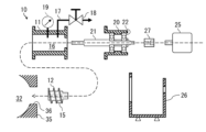
- FIG. 1 is an XY sectional view (AA sectional view of FIG. 3, which will be described later) of a vent device 10 installed in an extruder 30 in an embodiment of the present invention.
- FIG. 2 is an exploded sectional view of the vent device 10 according to the embodiment.
- the vent device 10 includes the cylindrical body 11 whose one end is externally connected to the through hole 36 that opens on the inner peripheral surface of the barrel hole 32 through which the molten and kneaded material is extruded in one direction (Z-axis direction).
- a spiral body 12 is positioned in the through hole 36 and has a spiral groove 15 formed on its outer circumferential surface and rotates on its axis inside the cylindrical body 11 . and a pipe 17 for discharging the gas or drain liquid that has flowed into the tank to the outside.
- a single spiral groove 15 is formed on the outer peripheral surface of the spiral body 12, but a plurality of spiral grooves 15 of two or more grooves may be formed in some cases.
- Such a spiral body 12 is coaxially arranged inside the cylindrical body 11, so that it connects to the barrel hole 32 of the cylinder 35 through the gap with the inner peripheral surface of the cylindrical body 11 and the spiral groove 15. It communicates with the internal space 16 of the shaped body 11.
- the through hole 36 opens on the side surface of the barrel hole 32 so that the central axis of the cylindrical body 11 faces in a direction perpendicular to the screw 31.
- One end of the cylindrical body 11 is connected to the outside of the through hole 36, and the other end is connected to a bearing portion 20 that rotatably supports the shaft 21 with a bearing 22.
- the cylindrical body 11 and the bearing part 20 are directly connected in the illustration, they may be connected via a spacer (not shown). By adjusting the length of this spacer (not shown), the position of the spiral body 12 in the through hole 36 can be adjusted.
- a motor 25 is connected to the base end of the shaft 21, which is opposite to the front end to which the spiral body 12 is fixed, via a shaft coupling 27. As this motor 25 rotates, the shaft 21 and the spiral body 12 at the tip rotate coaxially with respect to the central axis of the cylindrical body 11 . Although a mode is shown in which the rotating shaft of the motor 25 is directly connected to the shaft 21 of the helical body 12, the motor 25 can be arbitrarily laid out by being connected to the shaft 21 through various gears.
- the pipe 17 discharges the gas or drain liquid that has entered the internal space 16 of the cylindrical body 11 to the outside.
- the throttle valve 18 provided in the pipe 17 is not an essential component, it adjusts the amount of drain liquid discharged from the internal space 16 of the cylindrical body 11 to the outside by arbitrarily setting its opening degree.
- the illustrated piping 17 has its base end connected to the upper side of the cylindrical body 11 and has the function of mainly discharging gas, but the piping 17 whose base end is connected to the lower side of the cylindrical body 11 (not shown) In some cases, the main function is to discharge drain liquid.
- the throttle valve 18 provides variable flow resistance to the gas (water vapor) discharged from the internal space 16 to the atmosphere.
- the throttle valve 18 can arbitrarily set the internal pressure P of the internal space 16 measured by the pressure gauge 19 between the saturated vapor pressure P z and the atmospheric pressure P 0 at the set temperature of the melted and kneaded body. That is, when the throttle valve 18 is completely closed, the internal pressure of the internal space 16 is set to the saturated vapor pressure Pz , and when the throttle valve 18 is completely opened, the internal pressure is set to the atmospheric pressure P0 .
- a pressure reducing device to the tip of the pipe 17 the internal pressure of the internal space 16 can be set to below the atmospheric pressure P0 , promoting dehydration of the molten and kneaded material.
- the frame 26 supports the motor 25 and the bearing part 20, and is fixed to a pedestal 41 placed on the foundation 40.
- the component parts of the vent device 10 are configured so that the vent device 10 can be easily attached to and removed from the extruder 30, and disassembled and reassembled at the time of maintenance.
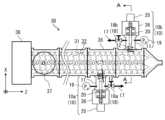
- FIG. 3 is a top perspective view of an extruder 30 equipped with a vent device 10 in an embodiment of the present invention.
- FIG. 4 is a side perspective view of the same.
- the extruder 30 includes an input section 37, a drive section 38, a cylinder 35, and a vent device 10.
- a screw 31 is provided inside the cylinder 35 and is rotated by the driving force of a driving section 38 .
- the screw 31 in FIG. 3 is configured with two screws, the extruder 30 is not limited to such a two-screw type, and may be configured with a single screw or three or more screws. In some cases.
- the input unit 37 inputs a mixture of synthetic resin and other compounds into the cylinder 35, which is a closed container. Since the cylinder 35 is set at a temperature at which the synthetic resin melts, the mixture is heated and kneaded by the rotation of the screw 31 to form a molten and kneaded body.
- the vent device 10 opens the cylinder 35, which is a closed container, and discharges the water contained in the molten and kneaded body to the outside.
- the molten kneaded body that has been dehydrated in the vent device 10 is discharged from the most downstream of the cylinder 35. Then, the discharged molten and kneaded body is formed into pellets or into a predetermined bulk product or film product.
- vent devices 10 (10a, 10b) are installed in two stages along the extrusion direction (Z-axis direction) of the melted and kneaded body, but there is no particular restriction on the number of stages installed. .
- the water contained in the molten and kneaded body is sequentially discharged from the vent device 10 (10a, 10b) in which the throttle amount of the throttle valve 18 (18a, 18b) is adjusted.
- a vent device including a decompression pump at the tip of the pipe 17 can be provided at the most downstream position.
- the throttle valve 18 for setting the internal pressure P b is set fully open.
- the throttle valve 18 is set so that the value P c of the pressure gauge 19 in this case is smaller than the atmospheric pressure P 0 (P 0 >P c ). .
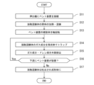
- vent device 10 is externally connected to the extruder 30, and the cylindrical body 11 and the barrel hole 32 are communicated with each other (S11). Then, the raw material is introduced into the input section 37, and the screw 31 is rotated to extrude it from upstream to downstream while heating and applying shear stress to make the raw material into a molten and kneaded body (S12).
- the spiral body 12 of the vent device 10 is rotated (S13). Then, the pressure of the molten and kneaded body pushed out to the opening position of the through hole 36 decreases, and the water contained therein vaporizes and expands at once. This vaporized and expanded moisture (water vapor) also involves the solid components of the molten and kneaded body and tries to fly out of the through hole 36. However, this solid component is pushed back by the rotating spiral body 12, cannot pass through the through hole 36, and is forced out further downstream of the barrel hole 32.
- moisture (steam) vaporized and expanded from the molten and kneaded body passes through the spiral body 12 from the barrel hole 32, passes through the through hole 36, and is trapped in the vent device 10a set to the internal pressure P a (S14 ). Then, the trapped water vapor (gas component) or the drain liquid in which the water vapor is condensed is discharged to the outside via the pipe 17 (S15).
- the molten and kneaded material that has passed through the vent device 10a on the upstream side of the barrel hole 32 is further trapped in moisture and discharged to the outside in the vent device 10b on the downstream side, which is set to an internal pressure P b ( ⁇ P a ).
- P b an internal pressure
- the molten kneaded body that has been dehydrated in the vent device 10 (10a, 10b) is discharged from the most downstream of the extruder 30 and is formed into pellets or a predetermined bulk product or film product ( S16 No, S17, END).
- SYMBOLS 10 Vent device, 11... Cylindrical body, 12... Spiral body, 15... Spiral groove, 16... Internal space, 17... Piping, 18... Throttle valve, 19... Pressure gauge, 20... Bearing part, 21... Shaft, 21... Bearing, 25... Motor, 26... Frame, 27... Shaft coupling, 30... Extruder, 31... Screw, 32... Barrel hole, 35... Cylinder, 36... Through hole, 37... Input part, 38... Drive part, 40... Foundation, 41... Frame, P (P a , P b )... Internal pressure, P 0 ... Atmospheric pressure.
Landscapes
- Engineering & Computer Science (AREA)
- Mechanical Engineering (AREA)
- Processing And Handling Of Plastics And Other Materials For Molding In General (AREA)
- Extrusion Moulding Of Plastics Or The Like (AREA)
Priority Applications (2)
| Application Number | Priority Date | Filing Date | Title |
|---|---|---|---|
| JP2024532384A JP7532705B2 (ja) | 2022-08-05 | 2022-08-05 | 押出機並びに押出機のベント装置及び押出機のベント方法 |
| PCT/JP2022/030087 WO2024029068A1 (ja) | 2022-08-05 | 2022-08-05 | 押出機のベント装置及び押出機のベント方法 |
Applications Claiming Priority (1)
| Application Number | Priority Date | Filing Date | Title |
|---|---|---|---|
| PCT/JP2022/030087 WO2024029068A1 (ja) | 2022-08-05 | 2022-08-05 | 押出機のベント装置及び押出機のベント方法 |
Publications (1)
| Publication Number | Publication Date |
|---|---|
| WO2024029068A1 true WO2024029068A1 (ja) | 2024-02-08 |
Family
ID=89848761
Family Applications (1)
| Application Number | Title | Priority Date | Filing Date |
|---|---|---|---|
| PCT/JP2022/030087 Ceased WO2024029068A1 (ja) | 2022-08-05 | 2022-08-05 | 押出機のベント装置及び押出機のベント方法 |
Country Status (2)
| Country | Link |
|---|---|
| JP (1) | JP7532705B2 (enExample) |
| WO (1) | WO2024029068A1 (enExample) |
Citations (4)
| Publication number | Priority date | Publication date | Assignee | Title |
|---|---|---|---|---|
| JPS59194925U (ja) * | 1983-06-11 | 1984-12-25 | 株式会社日本製鋼所 | 押出機用脱水装置 |
| JPH1170561A (ja) * | 1997-08-28 | 1999-03-16 | Mitsubishi Heavy Ind Ltd | 押出成形機 |
| JPH11268099A (ja) * | 1998-03-20 | 1999-10-05 | Japan Steel Works Ltd:The | 押出機の脱気口詰まり防止方法及び装置 |
| JP2015221565A (ja) * | 2014-05-22 | 2015-12-10 | コペリオン ゲーエムベーハー | 処理材料の脱揮装置及び方法 |
Family Cites Families (3)
| Publication number | Priority date | Publication date | Assignee | Title |
|---|---|---|---|---|
| JPS62191505A (ja) * | 1986-02-17 | 1987-08-21 | Teijin Ltd | 無乾燥高分子の溶融紡糸方法 |
| JP4068692B2 (ja) * | 1997-08-27 | 2008-03-26 | 三井化学株式会社 | 二軸押出機および二軸押出機の圧力制御方法 |
| JP3597070B2 (ja) * | 1999-01-20 | 2004-12-02 | 東芝機械株式会社 | 耐衝撃性熱可塑性樹脂の製造装置およびその方法 |
-
2022
- 2022-08-05 JP JP2024532384A patent/JP7532705B2/ja active Active
- 2022-08-05 WO PCT/JP2022/030087 patent/WO2024029068A1/ja not_active Ceased
Patent Citations (4)
| Publication number | Priority date | Publication date | Assignee | Title |
|---|---|---|---|---|
| JPS59194925U (ja) * | 1983-06-11 | 1984-12-25 | 株式会社日本製鋼所 | 押出機用脱水装置 |
| JPH1170561A (ja) * | 1997-08-28 | 1999-03-16 | Mitsubishi Heavy Ind Ltd | 押出成形機 |
| JPH11268099A (ja) * | 1998-03-20 | 1999-10-05 | Japan Steel Works Ltd:The | 押出機の脱気口詰まり防止方法及び装置 |
| JP2015221565A (ja) * | 2014-05-22 | 2015-12-10 | コペリオン ゲーエムベーハー | 処理材料の脱揮装置及び方法 |
Also Published As
| Publication number | Publication date |
|---|---|
| JPWO2024029068A1 (enExample) | 2024-02-08 |
| JP7532705B2 (ja) | 2024-08-13 |
Similar Documents
| Publication | Publication Date | Title |
|---|---|---|
| KR100743476B1 (ko) | 원추형 이축 스크류 압출기 및 탈수기 | |
| TWI602672B (zh) | 擠壓機用螺旋桿、擠壓機及擠壓方法 | |
| CN1721157B (zh) | 挤出机 | |
| JP2011051349A (ja) | 高分子複合材料の製造装置及びその製造方法 | |
| JP6524083B2 (ja) | 多層推進薬グレインを製造する方法 | |
| WO2024029068A1 (ja) | 押出機のベント装置及び押出機のベント方法 | |
| KR102760493B1 (ko) | 압출장치 | |
| US5887972A (en) | Extruder for plastic granules | |
| WO2007140926A1 (de) | Endreaktor | |
| US5630968A (en) | Water-injection foaming devolatilizing method | |
| JP5889115B2 (ja) | 混練押出成形装置 | |
| JP3597070B2 (ja) | 耐衝撃性熱可塑性樹脂の製造装置およびその方法 | |
| US20200055227A1 (en) | Vent Type Extruder and Method of Manufacturing Cable Jacket Using the Same | |
| JP3819340B2 (ja) | 溶融樹脂の脱揮方法及びその装置 | |
| KR101340482B1 (ko) | 벤트수단을 갖는 그루브드 배럴형 압출기 | |
| KR20210063643A (ko) | 압출장치 | |
| JPH065865Y2 (ja) | 二軸脱水押出機 | |
| JPS603918B2 (ja) | 連続圧搾機 | |
| US901237A (en) | Carbureter. | |
| JPH0550424A (ja) | 2軸押出機 | |
| CN116422000B (zh) | 一种多级连用碘结晶装置 | |
| JP2005014338A (ja) | 二軸脱水押出機 | |
| CN111372748A (zh) | 挤出机与挤出机的模具 | |
| JP2004130537A (ja) | 押出機および該押出機に用いられる通過量制御方法 | |
| RU1812115C (ru) | Черв чна машина дл обезвоживани каучука |
Legal Events
| Date | Code | Title | Description |
|---|---|---|---|
| 121 | Ep: the epo has been informed by wipo that ep was designated in this application |
Ref document number: 22954056 Country of ref document: EP Kind code of ref document: A1 |
|
| ENP | Entry into the national phase |
Ref document number: 2024532384 Country of ref document: JP Kind code of ref document: A |
|
| NENP | Non-entry into the national phase |
Ref country code: DE |
|
| 122 | Ep: pct application non-entry in european phase |
Ref document number: 22954056 Country of ref document: EP Kind code of ref document: A1 |