WO2024028972A1 - 開口数可変装置、レーザ装置およびレーザ加工機 - Google Patents
開口数可変装置、レーザ装置およびレーザ加工機 Download PDFInfo
- Publication number
- WO2024028972A1 WO2024028972A1 PCT/JP2022/029624 JP2022029624W WO2024028972A1 WO 2024028972 A1 WO2024028972 A1 WO 2024028972A1 JP 2022029624 W JP2022029624 W JP 2022029624W WO 2024028972 A1 WO2024028972 A1 WO 2024028972A1
- Authority
- WO
- WIPO (PCT)
- Prior art keywords
- laser
- numerical aperture
- laser beams
- transmission fiber
- transmission
- Prior art date
Links
Images


Classifications
-
- B—PERFORMING OPERATIONS; TRANSPORTING
- B23—MACHINE TOOLS; METAL-WORKING NOT OTHERWISE PROVIDED FOR
- B23K—SOLDERING OR UNSOLDERING; WELDING; CLADDING OR PLATING BY SOLDERING OR WELDING; CUTTING BY APPLYING HEAT LOCALLY, e.g. FLAME CUTTING; WORKING BY LASER BEAM
- B23K26/00—Working by laser beam, e.g. welding, cutting or boring
- B23K26/02—Positioning or observing the workpiece, e.g. with respect to the point of impact; Aligning, aiming or focusing the laser beam
- B23K26/06—Shaping the laser beam, e.g. by masks or multi-focusing
- B23K26/067—Dividing the beam into multiple beams, e.g. multifocusing
-
- B—PERFORMING OPERATIONS; TRANSPORTING
- B23—MACHINE TOOLS; METAL-WORKING NOT OTHERWISE PROVIDED FOR
- B23K—SOLDERING OR UNSOLDERING; WELDING; CLADDING OR PLATING BY SOLDERING OR WELDING; CUTTING BY APPLYING HEAT LOCALLY, e.g. FLAME CUTTING; WORKING BY LASER BEAM
- B23K26/00—Working by laser beam, e.g. welding, cutting or boring
- B23K26/02—Positioning or observing the workpiece, e.g. with respect to the point of impact; Aligning, aiming or focusing the laser beam
- B23K26/06—Shaping the laser beam, e.g. by masks or multi-focusing
- B23K26/064—Shaping the laser beam, e.g. by masks or multi-focusing by means of optical elements, e.g. lenses, mirrors or prisms
-
- G—PHYSICS
- G02—OPTICS
- G02B—OPTICAL ELEMENTS, SYSTEMS OR APPARATUS
- G02B6/00—Light guides; Structural details of arrangements comprising light guides and other optical elements, e.g. couplings
- G02B6/24—Coupling light guides
- G02B6/42—Coupling light guides with opto-electronic elements
- G02B6/4296—Coupling light guides with opto-electronic elements coupling with sources of high radiant energy, e.g. high power lasers, high temperature light sources
Definitions
- the present disclosure relates to a variable numerical aperture device, a laser device, and a laser processing machine that change the numerical aperture of incidence into a transmission fiber.
- a laser processing machine usually consists of a laser oscillator, a condensing lens that condenses the laser beam emitted from the laser oscillator, a transmission fiber that propagates the laser beam condensed by the condensing lens, and a laser beam from the transmission fiber. and a processing head that irradiates the desired position on the workpiece.
- a laser processing machine one is known that has a structure in which a plurality of laser beams are incident on one transmission fiber in order to increase the output.
- Patent Document 1 discloses a beam that changes the spatial distribution of a plurality of beams from a beam source having a polarization state and collectively has a spatial distribution, and converges the beams with the changed spatial distribution onto the end face of a transmission fiber.
- a parameter adjustment system is disclosed.
- the spatial distribution of the beam incident on the transmission fiber is changed by changing the respective polarization states, and the parameter product of the beam emitted from the transmission fiber is adjusted.
- Patent Document 1 when the technology described in Patent Document 1 is applied to a laser processing machine, if the axis of the incident laser beam on the light source side is coaxial with the incident axis of the transmission fiber, the laser beam reflected by the workpiece will be transmitted. The light returns to the laser oscillator, which is the light emitting source, with a distribution centered on the fiber's incident axis. There is also a problem in that the reflected laser light damages the laser oscillator.
- the present disclosure has been made in view of the above, and provides a variable numerical aperture device that can suppress damage to a laser oscillator caused by reflected laser light that returns with a distribution centered on the incident axis of a transmission fiber.
- the purpose is to obtain.
- the present disclosure rearranges the spatial distribution or spatial position of a plurality of laser beams incident from a laser oscillator, and generates a plurality of rearranged laser beams.
- a variable numerical aperture device that focuses light and makes it enter a transmission fiber, and is provided on an extension of the optical axis of the transmission fiber, and is a light shielding member that blocks reflected laser light that is laser light directed from the transmission fiber toward a laser oscillator. Equipped with
- variable numerical aperture device has the effect of suppressing damage to the laser oscillator caused by reflected laser light that returns in a distribution centered on the incident axis of the transmission fiber.
- a diagram showing an example of a change in the arrangement state of the laser beam in the XY plane in FIG. 4 A diagram showing an example of the hardware configuration of a control device of a laser processing machine according to Embodiment 1.
- variable numerical aperture device a laser device, and a laser processing machine according to embodiments of the present disclosure will be described in detail based on the drawings.
- FIG. 1 is a diagram schematically showing an example of the configuration of a laser processing machine according to the first embodiment.
- the laser processing machine 1 is a machine tool that processes a workpiece 61 by irradiating the workpiece 61 with a laser beam L, which is a laser beam.
- the laser processing machine 1 includes a laser device 10 that outputs a laser beam L, a transmission fiber 40 that propagates the laser beam L, a processing head 50 that irradiates a workpiece 61 with the laser beam L from the transmission fiber 40, and a workpiece 61. It includes a processing table 60 to support, and a control device 70 to control the entire laser processing machine 1.
- the laser device 10 includes a laser oscillator 20 that is a light source, and a variable numerical aperture device 30 that changes the numerical aperture (NA) of incidence into the transmission fiber 40.
- the laser oscillator 20 is a light source that emits laser beams LA and LB such as a solid-state laser, a gas laser, a semiconductor laser, or the like.
- the laser oscillator 20 emits a plurality of laser beams LA and LB.
- One laser oscillator 20 may emit a plurality of laser beams LA, LB, or a plurality of laser oscillators 20 may each emit one laser beam LA, LB.
- the laser oscillator 20 is arranged so that the positions of the plurality of laser beams LA and LB are symmetrical with respect to the extension line of the optical axis of the transmission fiber 40.
- the laser oscillator 20 makes a plurality of laser beams LA and LB enter the variable numerical aperture device 30.
- the variable numerical aperture device 30 rearranges the spatial distribution or spatial position of the plurality of laser beams LA, LB incident from the laser oscillator 20, and focuses the rearranged plurality of laser beams LA, LB.
- the laser oscillator 20 and the transmission fiber 40 are connected to each other by making the light incident on the input end of the transmission fiber 40 .
- a laser beam obtained by condensing the laser beams LA and LB propagating through the transmission fiber 40 is referred to as a laser beam L.
- the numerical aperture represents the magnitude of the light receiving angle and the output angle in the transmission fiber 40, and the variable numerical aperture device 30 can also be said to be a device that changes the entrance numerical aperture and the output numerical aperture of the transmission fiber 40.
- the acceptance angle of the transmission fiber 40 has a maximum value.
- the maximum value is the maximum acceptance angle at which the laser beam L can propagate through the transmission fiber 40 by total internal reflection.
- the entrance numerical aperture has a minimum value in addition to the one corresponding to the maximum value of the acceptance angle described above. The minimum value is determined by the beam quality output from the laser oscillator 20 and the structure of the variable numerical aperture device 30, which will be described later.
- the numerical aperture variable device 30 changes the entrance numerical aperture so that it is between the minimum value and the maximum value of the entrance numerical aperture.
- the entrance numerical aperture is determined by spatial distribution or spatial rearrangement of the plurality of laser beams LA, LB.
- FIG. 1 An example of rearranging the plurality of laser beams LA and LB is changing the beam interval of the plurality of laser beams LA and LB.
- the numerical aperture variable device 30 is schematically represented.
- the dashed arrow shown between the laser oscillator 20 and the input end of the transmission fiber 40 represents how the laser beams LA and LB pass through the variable numerical aperture device 30.
- the input end of the transmission fiber 40 is connected to the laser device 10, specifically the variable numerical aperture device 30, and the output end is connected to the processing head 50.
- the laser beam L propagated through the transmission fiber 40 enters the processing head 50.
- the transmission fiber 40 is an optical waveguide that propagates the laser beam L, and has a core and a cladding surrounding the core with a material having a lower refractive index than the core. With such a structure, the transmission fiber 40 propagates the laser beam L having an incident numerical aperture less than or equal to the maximum value of the incident numerical aperture of the transmission fiber 40 by total internal reflection.
- the processing head 50 is connected to the laser device 10 via the transmission fiber 40, and irradiates the workpiece 61 with the laser light L that propagates through the transmission fiber 40.
- the processing head 50 has a transmission optical system 51 that guides the laser beam L to the exit port of the processing head 50, and irradiates the laser beam L to a predetermined position on the workpiece 61.
- the transmission optical system 51 includes a condensing optical system that condenses the laser beam L from the transmission fiber 40.
- the laser beam L emitted from the processing head 50 is incident on the workpiece 61.
- a broken line arrow between the output end of the transmission fiber 40 and the workpiece 61 represents how the laser beam L emitted from the output end of the transmission fiber 40 reaches the workpiece 61.
- the processing table 60 is a table on which a workpiece 61 is placed. It is desirable that the processing table 60 has a fixing mechanism for fixing the work 61 so that the work 61 does not move during processing.
- the laser processing machine 1 moves the laser beam L and the workpiece 61 relative to each other by moving the processing table 60 with respect to the processing head 50.
- the laser processing machine 1 may be one that relatively moves the laser beam L and the workpiece 61 without moving the processing table 60.
- the laser processing machine 1 may fix the position of the processing table 60 and control the incident position of the laser beam L on the workpiece 61.
- the control device 70 sends control signals to each of the laser oscillator 20, variable numerical aperture device 30, processing head 50, and processing table 60, and controls their respective operations.
- Laser oscillator 20 outputs laser beams LA and LB according to the control signal.
- the variable numerical aperture device 30 operates according to the control signal and changes the numerical aperture of the laser beam L entering the transmission fiber 40 .
- Processing head 50 operates according to the control signal.
- Processing table 60 operates according to control signals. In this way, the control device 70 controls each of the laser oscillator 20, the variable numerical aperture device 30, the processing head 50, and the processing table 60.
- the processing section of the control device 70 that controls the operation of the variable numerical aperture device 30 is a control device that operates the variable numerical aperture device 30, and can be considered as a part of the variable numerical aperture device 30.
- the control device 70 adjusts the output numerical aperture at the output end of the transmission fiber 40 by changing the input numerical aperture to the transmission fiber 40 under the control of the variable numerical aperture device 30. That is, the variable numerical aperture device 30 and the control device 70 control the output numerical aperture of the transmission fiber 40 by controlling the input numerical aperture of the transmission fiber 40.
- FIG. 2 is a diagram schematically showing an example of the configuration of the variable numerical aperture device according to the first embodiment.
- the numerical aperture variable device 30 changes the interval between two laser beams LA and LB, the laser beam LA from the laser oscillator 20A and the laser beam LB from the laser oscillator 20B, and transmits A case is shown in which the numerical aperture of incidence on the fiber 40 is changed.
- the traveling direction of the laser beams LA, LB in the laser oscillators 20A, 20B is the Z-axis direction, and the two mutually perpendicular axes perpendicular to the Z-axis are the X-axis and Y-axis
- the laser oscillators 20A, 20B move in the Y-axis direction. shall be placed side by side along the Further, the laser oscillators 20A and 20B are arranged symmetrically with respect to an extension line that is an extension of the optical axis of the transmission fiber 40.
- the variable numerical aperture device 30 includes a beam interval changing unit 31 that changes the beam interval that is the interval between the plurality of laser beams LA and LB, and a beam interval changing unit 31 that focuses the laser beams LA and LB whose beam intervals have been changed onto the input end of the transmission fiber 40.
- a condensing optical system 33 that emits light is provided.
- the beam interval changing unit 31 has two or more beam interval changing units 32-1 and 32-2 when the beam characteristics of the plurality of laser beams LA and LB have directionality in the XY plane.
- the beam interval changing section 31 has two beam interval changing units 32-1 and 32-2.
- the beam spacing changing unit 32-1 changes the beam spacing in a first direction perpendicular to the Z-axis.
- the beam interval changing unit 32-2 changes the beam interval in a second direction different from the first direction.
- the beam interval changing unit 31 changes the beam interval ⁇ P1-1 of the laser beams LA and LB emitted from the laser oscillators 20A and 20B to a beam interval ⁇ P2-2.
- the first direction is the X-axis direction and the second direction is the Y-axis direction. Furthermore, changing the interval between the laser beams LA and LB changes the positions of the laser beams LA and LB within the XY plane. Therefore, the beam interval changing unit 31 can also be said to be a device that changes the arrangement of the plurality of laser beams LA and LB in the XY plane.
- the condensing optical system 33 condenses the laser beams LA and LB whose beam intervals have been changed by the beam interval changing unit 31, and makes them enter the transmission fiber 40.
- Condensing optical system 33 includes one or more lenses. In the example of FIG. 2, the condensing optical system 33 has one lens, but it may have two or more lenses. Note that when the condensing optical system 33 has two or more lenses, the numerical aperture NA_in of incidence to the transmission fiber 40 can also be changed in the condensing optical system 33.
- the transmission fiber 40 has a core 41 and a cladding 42 that surrounds the core 41 and is made of a material with a refractive index lower than that of the core 41.
- the laser beam L focused on the input end of the transmission fiber 40 follows a path indicated by a dotted line by total reflection, and is emitted from the output end with an output numerical aperture NA_out determined corresponding to the input numerical aperture NA_in.
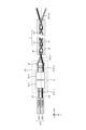
- FIG. 3 is a side view schematically showing an example of the configuration of the beam interval changing section in the variable numerical aperture device according to the first embodiment.
- the beam interval changing unit 31 includes the beam interval changing unit 32-1 and the beam interval changing unit 32-2.
- the beam interval changing unit 32-1 includes a beam rearrangement unit 321-1 that combines two planar transmission plates 322-1 and 323-1 that transmit the laser beams LA and LB, and a light shielding member 326-1. , has.
- the two transmission plates 322-1 and 323-1 of the beam rearrangement section 321-1 are rectangular plate-shaped planar substrates having the same size.
- the two transmission plates 322-1 and 323-1 are arranged at a predetermined interval in the Y-axis direction.
- a rotating shaft (not shown) is provided at the center of the transmission plate 322-1 in the ZX plane, and a rotating mechanism (not shown) is provided on the rotating shaft. As a result, the transmission plate 322-1 rotates around a rotation axis (not shown).
- a rotation shaft 325-1 is provided at the center of the transmission plate 323-1 in the ZX plane, and a rotation mechanism (not shown) is provided on the rotation shaft 325-1.
- the two transmission plates 322-1 and 323-1 are arranged to be tilted in opposite directions by the same angle ⁇ 1 with respect to a straight line A1 parallel to the X-axis passing through the rotating shaft 325-1.
- the transmission plate 322-1 is arranged at an angle ⁇ 1
- the transmission plate 323-1 is It is arranged tilted by an angle - ⁇ 1.
- the two transmission plates 322-1 and 323-1 are arranged symmetrically with respect to the optical axis of the transmission fiber 40.
- the rotation mechanism rotates the two transmission plates 322-1 and 323-1 according to instructions from the control device 70.
- the light shielding member 326-1 is a member that is disposed on the extension of the optical axis of the transmission fiber 40 and blocks reflected laser light that is laser light traveling from the transmission fiber 40 toward the laser oscillators 20A and 20B. In other words, the light shielding member 326-1 is arranged to prevent the reflected laser light reflected by the workpiece 61 from returning to the laser oscillator 20. In the example of FIG. 3, the light shielding member 326-1 is disposed between the two transmission plates 322-1 and 323-1, and has a shape extending in the X-axis direction.
- the beam interval changing unit 32-2 includes a beam rearrangement unit 321-2 that combines two planar transmission plates 322-2 and 323-2 that transmit the laser beams LA and LB, and a light shielding member 326-2. , has.
- the two transmission plates 322-2 and 323-2 of the beam rearrangement section 321-2 are rectangular plate-shaped planar substrates having the same size.
- the two transmission plates 322-2 and 323-2 are arranged at a predetermined interval in the X-axis direction.
- a rotation shaft 324-2 is provided at the center of the transmission plate 322-2 in the YZ plane, and a rotation mechanism (not shown) is provided on the rotation shaft 324-2. As a result, the transmission plate 322-2 rotates around the rotating shaft 324-2.
- a rotation shaft 325-2 is provided at the center of the transmission plate 323-2 in the YZ plane, and a rotation mechanism (not shown) is provided on the rotation shaft 325-2. As a result, the transmission plate 323-2 rotates around the rotating shaft 325-2.
- the two transmission plates 322-2 and 323-2 are arranged to be tilted by the same angle in opposite directions with respect to a straight line parallel to the Y-axis passing through the rotation axes 324-2 and 325-2. .
- the two transmission plates 322-2 and 323-2 are arranged symmetrically with respect to the optical axis of the transmission fiber 40.
- the rotation mechanism rotates the two transmission plates 322-2 and 323-2 according to instructions from the control device 70.
- the light shielding member 326-2 is arranged on the extension of the optical axis of the transmission fiber 40, and is a member that shields reflected laser light directed from the transmission fiber 40 toward the laser oscillators 20A and 20B. In other words, the light shielding member 326-2 is arranged to prevent the reflected laser light reflected by the workpiece 61 from returning to the laser oscillator 20. In one example, the light shielding member 326-2 may be disposed between two transmitting plates 322-2 and 323-2, and may have a shape extending in the Y-axis direction.
- the transmission plates 322-1, 322-2, 323-1, 323-2 are preferably made of an optically isotropic material that is transparent to the wavelengths of the laser beams LA and LB emitted by the laser oscillator 20.
- the laser oscillators 20A and 20B are fiber lasers that emit laser beams LA and LB around 1070 nm
- an example of the transmission plates 322-1, 322-2, 323-1, and 323-2 is glass such as synthetic quartz. It is a board.
- the light shielding members 326-1, 326-2 are provided for each of the plurality of beam interval changing units 32-1, 32-2, and are located on the transmission fiber 40 side of each beam interval changing unit 32-1, 32-2. do.
- the light shielding members 326-1 and 326-2 may be of any type as long as they reflect or absorb laser light.
- the material used for the light shielding members 326-1 and 326-2 depends on the wavelength of the laser beam L emitted by the laser oscillator 20.
- An example of the light shielding members 326-1 and 326-2 in which light is shielded by reflection is surface-treated copper.
- An example of the light shielding members 326-1 and 326-2 in the case where light shielding is performed by absorption is alumite-treated aluminum.
- the light shielding members 326-1 and 326-2 may have a cooling mechanism.
- the cooling mechanism includes piping provided inside the light shielding members 326-1, 326-2 or in contact with the light shielding members 326-1, 326-2, and a refrigerant supply section that flows a refrigerant into the piping.
- An example of a refrigerant is water.
- the light shielding member 326-1 is arranged between the two transmission plates 322-1 and 323-1, and the light shielding member 326-2 is arranged between the two transmission plates 322-2 and 323-2. .
- the light shielding member 326 of the plurality of laser beams LA and LB At least one of the dimensions and arrangement of the light shielding members 326-1 and 326-2 is determined so that the output loss due to kicking at -1 and 326-2 is 10% or less. Therefore, the shapes of the light shielding members 326-1 and 326-2 shown in FIG. 3 are merely examples, and other shapes may be used.
- the laser beams LA and LB have peak-shaped beam intensities. That is, the laser beams LA and LB have a Gaussian distribution in which the beam intensity is high at the center and decreases toward the periphery. In this case, the beam width where the beam intensity is lowered by 1/e 2 from the peak position is defined as the Gaussian beam diameter.
- the portion of the laser beams LA and LB that deviates from the Gaussian beam diameter is approximately 10% of the beam diameter of the laser beams LA and LB.
- the optical components constituting the laser processing machine 1 are generally optically designed to have a Gaussian beam diameter. For this reason as well, it is desirable that the design be such that the output loss due to the laser beams LA and LB being kicked by the light shielding members 326-1 and 326-2 is 10% or less.
- FIG. 4 is a diagram schematically showing an example of a method for changing the numerical aperture in the variable numerical aperture device according to the first embodiment.
- FIG. 4 only the beam interval changing units 32-1 and 32-2 of the variable numerical aperture device 30 of FIG. 2 are shown.
- FIG. 4 for convenience, a side view as viewed from the Y-axis direction, that is, a view on the ZX plane, and a side view as seen from the X-axis direction, that is, a view on the YZ plane are shown at the same time.
- the beam spacing changing unit 32-1 is placed on the laser oscillator 20 side, and the beam spacing changing unit 32-2 is placed on the transmission fiber 40 side. .
- the beam interval changing unit 32-1 changes the beam interval in the X-axis direction without changing the beam interval in the Y-axis direction, and the beam interval changing unit 32-2 does not change the beam interval in the X-axis direction. , change the beam spacing in the Y-axis direction.
- the beam interval changing unit 32-1 and the beam interval changing unit 32-2 may be units that change the beam interval in arbitrary directions that are different from each other.
- the transmission plates 322-1 and 323-1 of the beam interval changing unit 32-1 are rotated by ⁇ 1 and ⁇ 1, respectively, with respect to the straight line A1. Furthermore, the transmission plates 322-2 and 323-2 of the beam interval changing unit 32-2 are rotated by ⁇ 2 and ⁇ 2, respectively, with respect to the straight line A2.
- the straight line A2 is a straight line that passes through the rotation axes 324-2 and 325-2 and is parallel to the X-axis. ⁇ 1 and ⁇ 2 are each arbitrarily set so that the entrance numerical aperture NA_in of the transmission fiber 40 becomes a determined value.
- laser oscillators 20A and 20B are arranged symmetrically with respect to the optical axis of the transmission fiber 40 with an interval in the Y-axis direction.
- Laser beams LA and LB are output from laser oscillators 20A and 20B, respectively. It is assumed that the beam interval of the laser beams LA and LB in the X-axis direction is ⁇ P1-1x, and the beam interval in the Y-axis direction is ⁇ P1-1y.
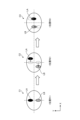
- FIG. 5 is a diagram showing an example of a change in the arrangement state of the laser beam in the XY plane in FIG. 4.
- the arrangement state in a plane perpendicular to the traveling direction of the laser beams LA and LB at positions R1, R2, and R3 in the optical path of the laser beams LA and LB in FIG. 4 is shown.
- the laser beams LA and LB are spaced apart in the Y-axis direction, as shown in the placement state C1 at the position R1.
- the laser beams LA and LB have a beam shape collapsed in the X-axis direction, that is, an elliptical beam shape with a longer diameter in the Y-axis direction than in the X-axis direction.
- the laser beams LA and LB enter the beam interval changing unit 32-1 in the arrangement state C1.
- the two transmission plates 322-1 and 323-1 are arranged at intervals in the Y-axis direction, and the rotational axes 324-1 and 325-1 are aligned with the Y-axis. become parallel.
- the transmission plate 322-1 is arranged so that the laser light LA from the laser oscillator 20A is transmitted therethrough
- the transmission plate 323-1 is arranged so that the laser light LB from the laser oscillator 20B is transmitted therethrough.
- the two transmission plates 322-1 and 323-1 are rotatable around the Y axis.
- the transmission plate 322-1 is arranged at an angle ⁇ 1 with respect to the straight line A1, and the transmission plate 323-1 is arranged at an angle ⁇ 1.
- the beam relocation unit 321-1 By arranging the beam relocation unit 321-1 in this manner, the beam interval in the X-axis direction can be changed.
- the laser beams LA and LB enter the beam interval changing unit 32-1.
- the laser beam LA is incident on the transmission plate 322-1
- the laser beam LB is incident on the transmission plate 323-1.
- the laser beams LA and LB are refracted when they enter the transmission plates 322-1 and 323-1.
- the laser beams LA and LB appear to be refracted in the direction with the incident angle, that is, within the ZX plane, and the laser beams LA and LB appear to travel straight in the direction without the incident angle, that is, within the YZ plane.
- the two transmission plates 322-1 and 323-1 are tilted in opposite directions by the same angle ⁇ 1 with respect to the straight line A1.
- the two laser beams LA and LB are refracted in the direction away from each other.
- the laser beams LA and LB are not refracted. Part of the laser beams LA and LB hits the light shielding member 326-1, but in the ZX plane, the laser beam LA passes through the back side of the light shielding member 326-1 in the Y-axis direction, and the laser light LB hits the light shielding member 326-1. 1 on the front side in the Y-axis direction.
- the arrangement state of the laser beams LA and LB output from the beam interval changing unit 32-1 is as shown in the arrangement state C2 at position R2 in FIG.
- the dotted ellipses in the arrangement state C2 indicate the positions of the laser beams LA and LB in the arrangement state C1.
- the laser beam LA and the laser beam LB move the same distance in opposite directions in the X-axis direction.
- the beam spacing in the X-axis direction of the laser beams LA and LB output from the beam spacing changing unit 32-1 is assumed to be ⁇ P1-2x
- the beam spacing in the Y-axis direction is assumed to be ⁇ P1-2y.
- the beam interval ⁇ P1-2x between the laser beams LA and LB in the X-axis direction output from the beam interval changing unit 32-1 is larger than the beam interval ⁇ P1-1x before incidence.
- the beam interval ⁇ P1-2y between the laser beams LA and LB in the Y-axis direction output from the beam relocation unit 321-1 is equal to the beam interval ⁇ P1-1y before incidence.
- the beam interval in the X-axis direction of the two laser beams LA and LB input to the beam interval changing unit 32-2 is assumed to be ⁇ P2-1x
- the beam interval in the Y-axis direction is assumed to be ⁇ P2-1y.
- the beam interval ⁇ P2-1x in the X-axis direction is equal to ⁇ P1-2x
- the beam interval ⁇ P2-1y in the Y-axis direction is equal to ⁇ P1-2y.
- These two laser beams LA and LB enter the beam interval changing unit 32-2.
- the laser beam LA is incident on the transmission plate 322-2
- the laser beam LB is incident on the transmission plate 323-2.
- the laser beams LA and LB are refracted when they enter the transmission plates 322-2 and 323-2.
- the laser beams LA and LB are refracted in the YZ plane, which is the direction with an incident angle
- the laser beams LA and LB are refracted in the ZX plane, which is the direction with no incident angle. Looks like it's going straight.
- the two transmission plates 322-2 and 323-2 are tilted in opposite directions by the same angle ⁇ 2 with respect to the straight line A2.
- the laser beams LA and LB are not refracted within the ZX plane.
- the two laser beams LA and LB are refracted in a direction toward each other. Part of the laser beams LA and LB hits the light shielding member 326-2, but in the YZ plane, the laser beam LA passes through the back side of the light shielding member 326-2, and the laser beam LB passes through the front side of the light shielding member 326-2. pass through.
- the beam spacing in the X-axis direction of the two laser beams LA and LB output from the beam spacing changing unit 32-2 becomes ⁇ P2-2x
- the beam spacing in the Y-axis direction becomes ⁇ P2-2y.
- the beam interval ⁇ P2-2x is equal to the beam interval ⁇ P2-1x in the X-axis direction of the two laser beams LA and LB before entering the beam interval changing unit 32-2.
- the beam interval ⁇ P2-2y is smaller than the beam interval ⁇ P2-1y in the Y-axis direction of the two laser beams LA and LB before entering the beam interval changing unit 32-2.
- the arrangement state of the laser beams LA and LB output from the beam interval changing unit 32-2 is as shown in the arrangement state C3 at position R3 in FIG.
- the dotted ellipses in the arrangement state C3 indicate the positions of the laser beams LA and LB in the arrangement state C2.
- the laser beam LA and the laser beam LB move the same distance in opposite directions in the Y-axis direction and are located on the X-axis.
- two elliptical laser beams LA and LB extending in the Y-axis direction and spaced apart in the Y-axis direction are connected to two beam interval changing units.
- they are arranged at intervals in the X-axis direction, as shown in arrangement state C3.
- the two beam interval changing units 32-1 and 32-2 make it possible to rearrange the laser beams LA and LB.
- the beam diameter and divergence angle when the laser beams L are combined can be adjusted by rearranging the laser beams LA and LB as described above. can be changed.
- beam quality is expressed as the product of beam diameter and divergence angle.
- the beam quality indicates that the smaller the value determined above is, the better the quality of the laser beams LA and LB is.
- the beam diameter in the case of one laser beam can be determined by the Gaussian beam diameter as described above.
- a beam diameter determined from the energy distribution formed by the plurality of laser beams LA and LB can be used.
- the beam diameter is considered to be the diameter in which a predetermined proportion of the energy of the laser beam is contained.
- the beam diameter when the plurality of laser beams LA and LB are combined differs depending on the arrangement of the plurality of laser beams LA and LB. As a result, the beam quality changes.
- the beam quality in the Y-axis direction is considered to be worse than the beam quality in the X-axis direction. Furthermore, when considering that the beam diameter is the area that contains a predetermined proportion of the total energy, the narrower the interval between the two laser beams LA and LB, the smaller the beam diameter. Considering these factors together, the beam quality is better in the arrangement state C3 in which the laser beams LA and LB are arranged in the X-axis direction than in the arrangement state C1 in which the laser beams LA and LB are arranged in the Y-axis direction with a gap between them. Conceivable. Therefore, in FIG. 4, the two laser beams LA and LB are rearranged from the arrangement state C1 to the arrangement state C3 using the two beam interval changing units 32-1 and 32-2.
- the beam interval changing unit 32-1 and the beam interval changing unit 32-2 change the beam interval in different directions, and the angle of inclination can also be set arbitrarily.
- the shape of the laser beams LA and LB in the XY plane has directionality in the X-axis and the Y-axis.
- the amount of displacement of the beam position in the X-axis direction and the Y-axis direction is set so that the numerical apertures of the beams are approximately the same in the X-axis direction and the Y-axis direction.
- the reason why the numerical aperture of the laser beam L is made to be approximately the same in the X-axis direction and the Y-axis direction is because the output numerical aperture NA_out of the transmission fiber 40 depends on the larger input numerical aperture NA_in.
- the relationship between the inclination angles of the transmission plates 322-1, 322-2, 323-1, and 323-2 and the beam spacing is determined in advance through experiments. By doing this, the transmission plates 322-1, 322- It becomes possible to obtain the inclination angle of 2,323-1,323-2.
- the best beam quality can be obtained by overlapping the plurality of laser beams LA and LB so that they match.
- the laser beam L from the processing head 50 is reflected by the workpiece 61, and the reflected laser beam may return to the laser oscillator 20 side with a distribution centered on the optical axis of the transmission fiber 40.
- a position corresponding to the optical axis of the transmission fiber 40 on the output side of the laser beams LA and LB of the respective beam interval changing units 32-1 and 32-2 is arranged.
- a beam interval that minimizes the beam quality of the two laser beams LA and LB is determined under the condition where the light shielding members 326-1 and 326-2 are present.
- the plurality of laser beams LA and LB must be arranged symmetrically with respect to the extension of the optical axis of the transmission fiber 40. This means that if the two laser beams LA and LB are not symmetrical with respect to the extension line of the optical axis of the transmission fiber 40, one of the two laser beams LA and LB will not be symmetrical to the other laser beam. This is because the angle of incidence is larger than that of light. Since the output numerical aperture NA_out of the transmission fiber 40 depends on the larger input numerical aperture NA_in, in order to reduce the output numerical aperture NA_out of the transmission fiber 40, it is necessary to decrease the input numerical aperture NA_in of the transmission fiber 40. be.
- the two laser beams LA and LB are arranged so that the output loss due to kicking by the light shielding members 326-1 and 326-2 is 10% or less, and the spatial distribution or spatial position of the two laser beams is brought closest to each other.
- the two laser beams LA and LB are arranged so as to be symmetrical with respect to the extension line of the optical axis of the transmission fiber 40, the input numerical aperture NA_in of the transmission fiber 40 is minimized.
- the laser light L that propagates through the transmission fiber 40 by total reflection is limited to the laser light L that enters the transmission fiber 40 at an angle less than or equal to the maximum acceptance angle.
- the laser beam L that is incident at an angle larger than the maximum acceptance angle of the transmission fiber 40 cannot propagate through the transmission fiber 40, becomes radiation light, and results in loss.
- the entrance numerical aperture NA_in of the transmission fiber 40 is at its maximum.
- variable numerical aperture device 30 adjusts the rotation angles of the transmission plates 322-1, 322-2, 323-1, 323-2 of the beam spacing changing units 32-1, 32-2.
- the input numerical aperture NA_in of the transmission fiber 40 can be varied between a minimum value and a maximum value. In other words, if the conditions fall between the minimum and maximum input numerical apertures, multiple laser beams can be It becomes possible to change the beam quality of the laser light L that combines the lights LA and LB, more specifically, the beam diameter or divergence angle.
- the operation of the beam interval changing units 32-1 and 32-2 may be limited so that the input numerical aperture NA_in does not become larger than the maximum value of the input numerical aperture of the transmission fiber 40.
- the output numerical aperture NA_out at the output end of the transmission fiber 40 changes depending on the input numerical aperture NA_in at the input end of the transmission fiber 40. That is, similarly to the input numerical aperture NA_in, the output numerical aperture NA_out of the transmission fiber 40 can be changed.
- the variable range of the output numerical aperture NA_out can also be changed from the input numerical aperture NA_out. It can be greatly changed depending on the numerical aperture NA_in.
- variable numerical aperture device 30 has two beam interval changing units 32-1 and 32-2, but this is only an example.
- the variable numerical aperture device 30 has two or more beam interval changing units. That's fine.
- the number of beam interval changing units may be one.
- the rotation axes 324-1, 325-1 of the beam interval changing unit 32-1 and the rotation axes 324-2, 325-2 of the beam interval changing unit 32-2 were perpendicular to each other, but this is also an example. be.
- the rotation axes 324-1, 325-1 of the beam spacing changing unit 32-1 and the rotation axes 324-2, 325-2 of the beam spacing changing unit 32-2 are perpendicular to the optical axis of the transmission fiber 40, and are mutually perpendicular to the optical axis of the transmission fiber 40. As long as the directions of the rotation axes 324-1, 324-2, 325-1, and 325-2 do not match, any direction may be used.
- the rotational positions of the beam repositioning units 321-1, 321-2 may be arbitrarily controlled; It may be configured such that a set angle is stored in advance and the rotation is performed at the set angle based on a command from the control device 70.
- the variable numerical aperture device 30 of the first embodiment rearranges a plurality of laser beams LA and LB, and focuses the rearranged plurality of laser beams LA and LB to make them enter a transmission fiber 40. It has a plurality of beam interval changing units 32-1 and 32-2 that change the incident numerical aperture NA_in of 40. Each of the plurality of beam interval changing units 32-1, 32-2 is provided on the transmission fiber 40 side, and has a light shielding member 326-1, 326-2 provided in a region including an extension of the optical axis of the transmission fiber 40. Be prepared.
- the reflected laser light that is reflected by the workpiece 61 and returns to the laser oscillator 20 side with a distribution centered on the optical axis of the transmission fiber 40 can be blocked without passing through to the laser oscillator 20 side.
- the output numerical aperture NA_out of the transmission fiber 40 can be controlled while suppressing the failure of the laser oscillator 20 due to reflected laser light. Further, even when there is a large amount of reflected laser light reflected by the workpiece 61, the laser oscillator 20 can be operated without malfunctioning.
- the beam interval changing unit 32-1 includes two transmission plates 322-1, 323-1 that are rotatable around rotating shafts 324-1, 325-1, and the respective transmission plates 322-1, 323-1. and a rotation mechanism for driving the rotation shafts 324-1 and 325-1 at arbitrary inclinations.
- the beam interval changing unit 32-2 rotates two transmission plates 322-2, 323-2 that are rotatable around rotation axes 324-2, 325-2, and the respective transmission plates 322-2, 323-2. It has a rotation mechanism that drives the shafts 324-2 and 325-2 to an arbitrary inclination.
- the laser processing machine 1 also includes a control device 70 that controls the inclinations of the transmission plates 322-1, 322-2, 323-1, and 323-2 via a rotation mechanism.
- the control device 70 determines the inclinations of the two transmission plates 322-1 and 323-1 of the beam interval changing unit 32-1 and the inclinations of the two transmission plates 322-2 and 323-2 of the beam interval changing unit 32-2.
- the beam interval between the laser beams LA and LB can be changed. That is, the entrance numerical aperture NA_in of the transmission fiber 40 can be controlled between the minimum value and the maximum value. Further, since the input numerical aperture NA_in can be varied over a wide range, the output numerical aperture NA_out of the transmission fiber 40 can also be varied over a wide range.
- the plurality of laser beams LA and LB are arranged symmetrically with respect to the extension line of the optical axis of the transmission fiber 40. That is, the laser oscillators 20A, 20B, the transmission plates 322-1, 323-1 of the beam interval changing unit 32-1, and the transmission plates 322-2, 323-2 of the beam interval changing unit 32-2, respectively. They were arranged symmetrically with respect to the extension line of the optical axis of the transmission fiber 40. Thereby, the beam quality of the laser beam L including the plurality of laser beams LA and LB can be made symmetrical. Further, even if the plurality of laser beams LA and LB do not have good beam quality, it is possible to rearrange the laser beams LA and LB so that the beam quality becomes better.
- control device 70 is realized by a processing circuit in which a processor executes software.
- the processing circuit that executes the software is, for example, the control circuit shown in FIG. 6.
- FIG. 6 is a diagram showing an example of the hardware configuration of the control device for the laser processing machine according to the first embodiment.
- the control circuit 100 includes an input section 101, a processor 102, a memory 103, and an output section 104.
- the input unit 101 is an interface circuit that receives data input from outside the control circuit 100 and provides it to the processor 102.
- the output unit 104 is an interface circuit that sends data from the processor 102 or the memory 103 to the outside of the control circuit 100.
- the processing circuit is the control circuit 100 shown in FIG. 6, the processor 102 reads and executes a program stored in the memory 103 that controls the laser oscillator 20, variable numerical aperture device 30, processing head 50, and processing table 60. By doing so, each of the above components is realized.
- the memory 103 is also used as temporary memory in each process performed by the processor 102.
- the processor 102 may output data such as calculation results to the memory 103 for storage, or may store data such as calculation results in an auxiliary storage device via the volatile memory of the memory 103.
- the processor 102 is a CPU (Central Processing Unit, also referred to as a central processing unit, processing unit, arithmetic unit, microprocessor, microcomputer, processor, or DSP (Digital Signal Processor)).
- the memory 103 is, for example, RAM (Random Access Memory), ROM (Read Only Memory), flash memory, EPROM (Erasable Programmable Read Only Memory), or EEPROM (registered trademark) (Electrically Erasable Programmable Read Only Memory). ory), etc., non-volatile Alternatively, volatile semiconductor memory, magnetic disk, flexible disk, optical disk, compact disk, mini disk, DVD (Digital Versatile Disc), etc. are applicable.
- FIG. 6 shows an example of hardware in which the control device 70 is implemented using a general-purpose processor 102 and a memory 103
- the control device 70 may also be implemented using a dedicated hardware circuit.
- the processing circuit which is a dedicated hardware circuit, can be a single circuit, a composite circuit, a programmed processor, a parallel programmed processor, an ASIC (Application Specific Integrated Circuit), an FPGA (Field Programmable Gate Array), or a combination of these. It is a circuit.
- Each of the above components may be realized by a combination of the control circuit 100 and a dedicated hardware circuit.
- the configuration shown in the above embodiments is an example, and it is possible to combine it with another known technology, and a part of the configuration can be omitted or changed without departing from the gist. It is possible.
- 1 Laser processing machine 10 Laser device, 20, 20A, 20B Laser oscillator, 30 Numerical aperture variable device, 31 Beam spacing changing unit, 32-1, 32-2 Beam spacing changing unit, 33 Condensing optical system, 40 Transmission fiber , 41 core, 42 cladding, 50 processing head, 51 transmission optical system, 60 processing table, 61 workpiece, 70 control device, 100 control circuit, 101 input section, 102 processor, 103 memory, 104 output section, 321-1, 321 -2 Beam relocation unit, 322-1, 322-2, 323-1, 323-2 Transmission plate, 324-1, 324-2, 325-1, 325-2 Rotation shaft, 326-1, 326-2 Light shielding member, A1, A2 straight line, L, LA, LB laser beam.
Landscapes
- Physics & Mathematics (AREA)
- Optics & Photonics (AREA)
- Engineering & Computer Science (AREA)
- Plasma & Fusion (AREA)
- Mechanical Engineering (AREA)
- General Physics & Mathematics (AREA)
- Laser Beam Processing (AREA)
- Optical Couplings Of Light Guides (AREA)
Abstract
Description
図1は、実施の形態1に係るレーザ加工機の構成の一例を模式的に示す図である。レーザ加工機1は、レーザビームであるレーザ光Lを被加工物であるワーク61へ照射することによってワーク61を加工する工作機械である。
Claims (10)
- レーザ発振器から入射される複数のレーザ光の空間的な分布または空間的な位置を再配置し、再配置された前記複数のレーザ光を集光して伝送ファイバに入射させる開口数可変装置であって、
前記伝送ファイバの光軸の延長線上に設けられ、前記伝送ファイバから前記レーザ発振器に向かうレーザ光である反射レーザ光を遮光する遮光部材を備えることを特徴とする開口数可変装置。 - 前記遮光部材は、前記開口数可変装置の内部で、入射される前記複数のレーザ光の空間的な分布または空間的な位置を最接近させたときに、前記複数のレーザ光の出力損失が10%以下となる寸法を有することを特徴とする請求項1に記載の開口数可変装置。
- 前記遮光部材は、前記開口数可変装置の内部で、入射される前記複数のレーザ光の空間的な分布または空間的な位置を最接近させたときに、前記複数のレーザ光の出力損失が10%以下となるように配置されることを特徴とする請求項1または2に記載の開口数可変装置。
- 前記遮光部材は、前記反射レーザ光を吸収または反射する材料によって構成されることを特徴とする請求項1から3のいずれか1つに記載の開口数可変装置。
- 前記遮光部材は、冷却機構を有することを特徴とする請求項4に記載の開口数可変装置。
- 入射される前記複数のレーザ光のビーム間隔を変更する複数のビーム間隔変更ユニットを備え、
前記遮光部材は、前記複数のビーム間隔変更ユニットごとに設けられるとともに前記ビーム間隔変更ユニットの前記伝送ファイバ側に位置することを特徴とする請求項1から5のいずれか1つに記載の開口数可変装置。 - 前記複数のビーム間隔変更ユニットの動作を制御する制御装置をさらに備え、
前記複数のビーム間隔変更ユニットのそれぞれは、
前記レーザ光を透過する複数の透過板を定められた間隔をおいて配置したビーム再配置部と、
回転軸を中心に前記複数の透過板のそれぞれを回転させる回転機構と、
を有し、
前記制御装置は、前記複数のレーザ光の前記複数の透過板への入射角が定められた角度となるように前記回転機構を制御することを特徴とする請求項6に記載の開口数可変装置。 - 前記複数のレーザ光は、前記開口数可変装置において、前記伝送ファイバの光軸の延長線に対して対称に入射され、
前記複数の透過板は、前記伝送ファイバの光軸の延長線に対して対称に配置されることを特徴とする請求項7に記載の開口数可変装置。 - 請求項1から8のいずれか1つに記載の開口数可変装置と、
前記開口数可変装置に前記複数のレーザ光を入射させる前記レーザ発振器と、
を備えることを特徴とするレーザ装置。 - 請求項9に記載のレーザ装置と、
前記レーザ装置からの前記複数のレーザ光を伝搬する伝送ファイバと、
前記伝送ファイバからの前記複数のレーザ光を被加工物に照射する加工ヘッドと、
を備えることを特徴とするレーザ加工機。
Priority Applications (5)
| Application Number | Priority Date | Filing Date | Title |
|---|---|---|---|
| US18/878,658 US20250170672A1 (en) | 2022-08-02 | 2022-08-02 | Numerical aperture changing apparatus, laser apparatus, and laser beam machine |
| JP2022579057A JP7237261B1 (ja) | 2022-08-02 | 2022-08-02 | 開口数可変装置、レーザ装置およびレーザ加工機 |
| CN202280096831.6A CN119317506A (zh) | 2022-08-02 | 2022-08-02 | 数值孔径可变装置、激光器装置及激光加工机 |
| DE112022007071.4T DE112022007071T5 (de) | 2022-08-02 | 2022-08-02 | Vorrichtung zum Ändern der numerischen Apertur, Laservorrichtung und Laserstrahlmaschine |
| PCT/JP2022/029624 WO2024028972A1 (ja) | 2022-08-02 | 2022-08-02 | 開口数可変装置、レーザ装置およびレーザ加工機 |
Applications Claiming Priority (1)
| Application Number | Priority Date | Filing Date | Title |
|---|---|---|---|
| PCT/JP2022/029624 WO2024028972A1 (ja) | 2022-08-02 | 2022-08-02 | 開口数可変装置、レーザ装置およびレーザ加工機 |
Publications (1)
| Publication Number | Publication Date |
|---|---|
| WO2024028972A1 true WO2024028972A1 (ja) | 2024-02-08 |
Family
ID=85503266
Family Applications (1)
| Application Number | Title | Priority Date | Filing Date |
|---|---|---|---|
| PCT/JP2022/029624 WO2024028972A1 (ja) | 2022-08-02 | 2022-08-02 | 開口数可変装置、レーザ装置およびレーザ加工機 |
Country Status (5)
| Country | Link |
|---|---|
| US (1) | US20250170672A1 (ja) |
| JP (1) | JP7237261B1 (ja) |
| CN (1) | CN119317506A (ja) |
| DE (1) | DE112022007071T5 (ja) |
| WO (1) | WO2024028972A1 (ja) |
Citations (5)
| Publication number | Priority date | Publication date | Assignee | Title |
|---|---|---|---|---|
| JPH07227686A (ja) * | 1994-02-22 | 1995-08-29 | Mitsubishi Electric Corp | 光伝送装置及び光照射方法 |
| WO2008096863A1 (ja) * | 2007-02-09 | 2008-08-14 | Fujikura Ltd. | ファイバレーザ |
| JP2017506769A (ja) * | 2014-02-26 | 2017-03-09 | ビエン チャン, | 可変ビームパラメータ積を有するマルチビームレーザ配列のためのシステムおよび方法 |
| WO2019176502A1 (ja) * | 2018-03-15 | 2019-09-19 | パナソニックIpマネジメント株式会社 | レーザ発振器、それを用いたレーザ加工装置及びレーザ発振方法 |
| JP2020199513A (ja) * | 2019-06-07 | 2020-12-17 | 株式会社アマダ | レーザ加工機及びレーザ加工機の制御方法 |
Family Cites Families (4)
| Publication number | Priority date | Publication date | Assignee | Title |
|---|---|---|---|---|
| JP5064778B2 (ja) * | 2006-12-11 | 2012-10-31 | オリンパス株式会社 | レーザ加工装置 |
| DE102017210350B3 (de) * | 2017-06-21 | 2018-03-29 | Trumpf Laser Gmbh | Vorrichtung zur Auskopplung von Strahlung aus einer Lichtleitfaser, Lichtleitkabel und Bearbeitungskopf damit |
| JP7437745B2 (ja) * | 2020-03-13 | 2024-02-26 | パナソニックIpマネジメント株式会社 | レーザ発振器及びレーザ加工装置 |
| JP7579112B2 (ja) * | 2020-11-11 | 2024-11-07 | Jswアクティナシステム株式会社 | レーザ照射装置、及び半導体装置の製造方法 |
-
2022
- 2022-08-02 JP JP2022579057A patent/JP7237261B1/ja active Active
- 2022-08-02 CN CN202280096831.6A patent/CN119317506A/zh active Pending
- 2022-08-02 DE DE112022007071.4T patent/DE112022007071T5/de active Pending
- 2022-08-02 US US18/878,658 patent/US20250170672A1/en active Pending
- 2022-08-02 WO PCT/JP2022/029624 patent/WO2024028972A1/ja active Application Filing
Patent Citations (5)
| Publication number | Priority date | Publication date | Assignee | Title |
|---|---|---|---|---|
| JPH07227686A (ja) * | 1994-02-22 | 1995-08-29 | Mitsubishi Electric Corp | 光伝送装置及び光照射方法 |
| WO2008096863A1 (ja) * | 2007-02-09 | 2008-08-14 | Fujikura Ltd. | ファイバレーザ |
| JP2017506769A (ja) * | 2014-02-26 | 2017-03-09 | ビエン チャン, | 可変ビームパラメータ積を有するマルチビームレーザ配列のためのシステムおよび方法 |
| WO2019176502A1 (ja) * | 2018-03-15 | 2019-09-19 | パナソニックIpマネジメント株式会社 | レーザ発振器、それを用いたレーザ加工装置及びレーザ発振方法 |
| JP2020199513A (ja) * | 2019-06-07 | 2020-12-17 | 株式会社アマダ | レーザ加工機及びレーザ加工機の制御方法 |
Also Published As
| Publication number | Publication date |
|---|---|
| CN119317506A (zh) | 2025-01-14 |
| JPWO2024028972A1 (ja) | 2024-02-08 |
| JP7237261B1 (ja) | 2023-03-10 |
| DE112022007071T5 (de) | 2025-03-06 |
| US20250170672A1 (en) | 2025-05-29 |
Similar Documents
| Publication | Publication Date | Title |
|---|---|---|
| US11635667B2 (en) | Systems and methods for laser systems with variable beam parameter product utilizing thermo-optic effects | |
| US11327235B2 (en) | Methods of producing radiation beams with altered properties | |
| KR101004497B1 (ko) | 낮은 흡광 물질로 구성된 소재 내로 방사 에너지를 유도하기 위한 빔 형성 유닛을 포함하는 장치 | |
| US11480846B2 (en) | Systems and methods for laser systems with variable beam parameter product | |
| US10261271B2 (en) | Laser systems with variable beam parameter product utilizing uniaxial crystals or beam splitters | |
| US11204506B2 (en) | Polarization-adjusted and shape-adjusted beam operation for materials processing | |
| CN104950438B (zh) | 光照射装置与绘制装置 | |
| JP2720811B2 (ja) | レーザ集光方法及び装置 | |
| CN110036320B (zh) | 光纤耦合装置 | |
| JP7237261B1 (ja) | 開口数可変装置、レーザ装置およびレーザ加工機 | |
| KR20190001631A (ko) | 균질화된 레이저 빔의 사이즈를 가변시키는 광학 시스템 | |
| US6434284B1 (en) | Beam converter for enhancing brightness of polarized light sources | |
| KR20210131510A (ko) | 라인 빔 형성 장치 | |
| JP5068332B2 (ja) | レーザビーム装置 | |
| KR102489536B1 (ko) | 기판 처리 장치 및 광 경로 조절 장치 | |
| US7810938B2 (en) | Laser configuration | |
| KR101850365B1 (ko) | 레이저 가공 장치, 이를 이용한 레이저 가공 방법 및 이에 사용되는 레이저 조사 유닛 | |
| JP3792193B2 (ja) | 線状光照射装置 | |
| JP4440049B2 (ja) | レーザアニール装置 | |
| KR20250085573A (ko) | 레이저 가공 장치 | |
| TW202448613A (zh) | 雷射加工裝置 | |
| KR20230092043A (ko) | 레이저 가공 장치 | |
| JPH05289118A (ja) | 集光点位置調整方法 |
Legal Events
| Date | Code | Title | Description |
|---|---|---|---|
| ENP | Entry into the national phase |
Ref document number: 2022579057 Country of ref document: JP Kind code of ref document: A |
|
| 121 | Ep: the epo has been informed by wipo that ep was designated in this application |
Ref document number: 22953961 Country of ref document: EP Kind code of ref document: A1 |
|
| WWE | Wipo information: entry into national phase |
Ref document number: 112022007071 Country of ref document: DE |
|
| WWE | Wipo information: entry into national phase |
Ref document number: 18878658 Country of ref document: US |
|
| WWP | Wipo information: published in national office |
Ref document number: 112022007071 Country of ref document: DE |
|
| WWP | Wipo information: published in national office |
Ref document number: 18878658 Country of ref document: US |