WO2024024443A1 - マニホールド - Google Patents
マニホールド Download PDFInfo
- Publication number
- WO2024024443A1 WO2024024443A1 PCT/JP2023/025133 JP2023025133W WO2024024443A1 WO 2024024443 A1 WO2024024443 A1 WO 2024024443A1 JP 2023025133 W JP2023025133 W JP 2023025133W WO 2024024443 A1 WO2024024443 A1 WO 2024024443A1
- Authority
- WO
- WIPO (PCT)
- Prior art keywords
- flow path
- refrigerant
- internal
- flow
- path
- Prior art date
- Legal status (The legal status is an assumption and is not a legal conclusion. Google has not performed a legal analysis and makes no representation as to the accuracy of the status listed.)
- Ceased
Links
Images






Classifications
-
- F—MECHANICAL ENGINEERING; LIGHTING; HEATING; WEAPONS; BLASTING
- F25—REFRIGERATION OR COOLING; COMBINED HEATING AND REFRIGERATION SYSTEMS; HEAT PUMP SYSTEMS; MANUFACTURE OR STORAGE OF ICE; LIQUEFACTION SOLIDIFICATION OF GASES
- F25B—REFRIGERATION MACHINES, PLANTS OR SYSTEMS; COMBINED HEATING AND REFRIGERATION SYSTEMS; HEAT PUMP SYSTEMS
- F25B41/00—Fluid-circulation arrangements
- F25B41/40—Fluid line arrangements
- F25B41/42—Arrangements for diverging or converging flows, e.g. branch lines or junctions
-
- B—PERFORMING OPERATIONS; TRANSPORTING
- B60—VEHICLES IN GENERAL
- B60K—ARRANGEMENT OR MOUNTING OF PROPULSION UNITS OR OF TRANSMISSIONS IN VEHICLES; ARRANGEMENT OR MOUNTING OF PLURAL DIVERSE PRIME-MOVERS IN VEHICLES; AUXILIARY DRIVES FOR VEHICLES; INSTRUMENTATION OR DASHBOARDS FOR VEHICLES; ARRANGEMENTS IN CONNECTION WITH COOLING, AIR INTAKE, GAS EXHAUST OR FUEL SUPPLY OF PROPULSION UNITS IN VEHICLES
- B60K11/00—Arrangement in connection with cooling of propulsion units
- B60K11/02—Arrangement in connection with cooling of propulsion units with liquid cooling
-
- B—PERFORMING OPERATIONS; TRANSPORTING
- B60—VEHICLES IN GENERAL
- B60H—ARRANGEMENTS OF HEATING, COOLING, VENTILATING OR OTHER AIR-TREATING DEVICES SPECIALLY ADAPTED FOR PASSENGER OR GOODS SPACES OF VEHICLES
- B60H1/00—Heating, cooling or ventilating devices
- B60H1/00485—Valves for air-conditioning devices, e.g. thermostatic valves
-
- B—PERFORMING OPERATIONS; TRANSPORTING
- B60—VEHICLES IN GENERAL
- B60L—PROPULSION OF ELECTRICALLY-PROPELLED VEHICLES; SUPPLYING ELECTRIC POWER FOR AUXILIARY EQUIPMENT OF ELECTRICALLY-PROPELLED VEHICLES; ELECTRODYNAMIC BRAKE SYSTEMS FOR VEHICLES IN GENERAL; MAGNETIC SUSPENSION OR LEVITATION FOR VEHICLES; MONITORING OPERATING VARIABLES OF ELECTRICALLY-PROPELLED VEHICLES; ELECTRIC SAFETY DEVICES FOR ELECTRICALLY-PROPELLED VEHICLES
- B60L1/00—Supplying electric power to auxiliary equipment of vehicles
- B60L1/02—Supplying electric power to auxiliary equipment of vehicles to electric heating circuits
-
- B—PERFORMING OPERATIONS; TRANSPORTING
- B60—VEHICLES IN GENERAL
- B60L—PROPULSION OF ELECTRICALLY-PROPELLED VEHICLES; SUPPLYING ELECTRIC POWER FOR AUXILIARY EQUIPMENT OF ELECTRICALLY-PROPELLED VEHICLES; ELECTRODYNAMIC BRAKE SYSTEMS FOR VEHICLES IN GENERAL; MAGNETIC SUSPENSION OR LEVITATION FOR VEHICLES; MONITORING OPERATING VARIABLES OF ELECTRICALLY-PROPELLED VEHICLES; ELECTRIC SAFETY DEVICES FOR ELECTRICALLY-PROPELLED VEHICLES
- B60L58/00—Methods or circuit arrangements for monitoring or controlling batteries or fuel cells, specially adapted for electric vehicles
- B60L58/10—Methods or circuit arrangements for monitoring or controlling batteries or fuel cells, specially adapted for electric vehicles for monitoring or controlling batteries
- B60L58/24—Methods or circuit arrangements for monitoring or controlling batteries or fuel cells, specially adapted for electric vehicles for monitoring or controlling batteries for controlling the temperature of batteries
- B60L58/26—Methods or circuit arrangements for monitoring or controlling batteries or fuel cells, specially adapted for electric vehicles for monitoring or controlling batteries for controlling the temperature of batteries by cooling
-
- F—MECHANICAL ENGINEERING; LIGHTING; HEATING; WEAPONS; BLASTING
- F25—REFRIGERATION OR COOLING; COMBINED HEATING AND REFRIGERATION SYSTEMS; HEAT PUMP SYSTEMS; MANUFACTURE OR STORAGE OF ICE; LIQUEFACTION SOLIDIFICATION OF GASES
- F25B—REFRIGERATION MACHINES, PLANTS OR SYSTEMS; COMBINED HEATING AND REFRIGERATION SYSTEMS; HEAT PUMP SYSTEMS
- F25B25/00—Machines, plants or systems, using a combination of modes of operation covered by two or more of the groups F25B1/00 - F25B23/00
- F25B25/005—Machines, plants or systems, using a combination of modes of operation covered by two or more of the groups F25B1/00 - F25B23/00 using primary and secondary systems
-
- F—MECHANICAL ENGINEERING; LIGHTING; HEATING; WEAPONS; BLASTING
- F25—REFRIGERATION OR COOLING; COMBINED HEATING AND REFRIGERATION SYSTEMS; HEAT PUMP SYSTEMS; MANUFACTURE OR STORAGE OF ICE; LIQUEFACTION SOLIDIFICATION OF GASES
- F25B—REFRIGERATION MACHINES, PLANTS OR SYSTEMS; COMBINED HEATING AND REFRIGERATION SYSTEMS; HEAT PUMP SYSTEMS
- F25B39/00—Evaporators; Condensers
- F25B39/02—Evaporators
-
- F—MECHANICAL ENGINEERING; LIGHTING; HEATING; WEAPONS; BLASTING
- F25—REFRIGERATION OR COOLING; COMBINED HEATING AND REFRIGERATION SYSTEMS; HEAT PUMP SYSTEMS; MANUFACTURE OR STORAGE OF ICE; LIQUEFACTION SOLIDIFICATION OF GASES
- F25B—REFRIGERATION MACHINES, PLANTS OR SYSTEMS; COMBINED HEATING AND REFRIGERATION SYSTEMS; HEAT PUMP SYSTEMS
- F25B41/00—Fluid-circulation arrangements
- F25B41/40—Fluid line arrangements
-
- F—MECHANICAL ENGINEERING; LIGHTING; HEATING; WEAPONS; BLASTING
- F28—HEAT EXCHANGE IN GENERAL
- F28F—DETAILS OF HEAT-EXCHANGE AND HEAT-TRANSFER APPARATUS, OF GENERAL APPLICATION
- F28F9/00—Casings; Header boxes; Auxiliary supports for elements; Auxiliary members within casings
- F28F9/02—Header boxes; End plates
- F28F9/026—Header boxes; End plates with static flow control means, e.g. with means for uniformly distributing heat exchange media into conduits
- F28F9/0263—Header boxes; End plates with static flow control means, e.g. with means for uniformly distributing heat exchange media into conduits by varying the geometry or cross-section of header box
-
- F—MECHANICAL ENGINEERING; LIGHTING; HEATING; WEAPONS; BLASTING
- F28—HEAT EXCHANGE IN GENERAL
- F28F—DETAILS OF HEAT-EXCHANGE AND HEAT-TRANSFER APPARATUS, OF GENERAL APPLICATION
- F28F9/00—Casings; Header boxes; Auxiliary supports for elements; Auxiliary members within casings
- F28F9/02—Header boxes; End plates
- F28F9/026—Header boxes; End plates with static flow control means, e.g. with means for uniformly distributing heat exchange media into conduits
- F28F9/0265—Header boxes; End plates with static flow control means, e.g. with means for uniformly distributing heat exchange media into conduits by using guiding means or impingement means inside the header box
-
- H—ELECTRICITY
- H01—ELECTRIC ELEMENTS
- H01M—PROCESSES OR MEANS, e.g. BATTERIES, FOR THE DIRECT CONVERSION OF CHEMICAL ENERGY INTO ELECTRICAL ENERGY
- H01M10/00—Secondary cells; Manufacture thereof
- H01M10/60—Heating or cooling; Temperature control
- H01M10/61—Types of temperature control
- H01M10/613—Cooling or keeping cold
-
- H—ELECTRICITY
- H01—ELECTRIC ELEMENTS
- H01M—PROCESSES OR MEANS, e.g. BATTERIES, FOR THE DIRECT CONVERSION OF CHEMICAL ENERGY INTO ELECTRICAL ENERGY
- H01M10/00—Secondary cells; Manufacture thereof
- H01M10/60—Heating or cooling; Temperature control
- H01M10/62—Heating or cooling; Temperature control specially adapted for specific applications
- H01M10/625—Vehicles
-
- H—ELECTRICITY
- H01—ELECTRIC ELEMENTS
- H01M—PROCESSES OR MEANS, e.g. BATTERIES, FOR THE DIRECT CONVERSION OF CHEMICAL ENERGY INTO ELECTRICAL ENERGY
- H01M10/00—Secondary cells; Manufacture thereof
- H01M10/60—Heating or cooling; Temperature control
- H01M10/65—Means for temperature control structurally associated with the cells
- H01M10/656—Means for temperature control structurally associated with the cells characterised by the type of heat-exchange fluid
- H01M10/6567—Liquids
- H01M10/6568—Liquids characterised by flow circuits, e.g. loops, located externally to the cells or cell casings
-
- H—ELECTRICITY
- H01—ELECTRIC ELEMENTS
- H01M—PROCESSES OR MEANS, e.g. BATTERIES, FOR THE DIRECT CONVERSION OF CHEMICAL ENERGY INTO ELECTRICAL ENERGY
- H01M10/00—Secondary cells; Manufacture thereof
- H01M10/60—Heating or cooling; Temperature control
- H01M10/66—Heat-exchange relationships between the cells and other systems, e.g. central heating systems or fuel cells
- H01M10/663—Heat-exchange relationships between the cells and other systems, e.g. central heating systems or fuel cells the system being an air-conditioner or an engine
-
- B—PERFORMING OPERATIONS; TRANSPORTING
- B60—VEHICLES IN GENERAL
- B60K—ARRANGEMENT OR MOUNTING OF PROPULSION UNITS OR OF TRANSMISSIONS IN VEHICLES; ARRANGEMENT OR MOUNTING OF PLURAL DIVERSE PRIME-MOVERS IN VEHICLES; AUXILIARY DRIVES FOR VEHICLES; INSTRUMENTATION OR DASHBOARDS FOR VEHICLES; ARRANGEMENTS IN CONNECTION WITH COOLING, AIR INTAKE, GAS EXHAUST OR FUEL SUPPLY OF PROPULSION UNITS IN VEHICLES
- B60K1/00—Arrangement or mounting of electrical propulsion units
- B60K2001/003—Arrangement or mounting of electrical propulsion units with means for cooling the electrical propulsion units
- B60K2001/005—Arrangement or mounting of electrical propulsion units with means for cooling the electrical propulsion units the electric storage means
-
- B—PERFORMING OPERATIONS; TRANSPORTING
- B60—VEHICLES IN GENERAL
- B60L—PROPULSION OF ELECTRICALLY-PROPELLED VEHICLES; SUPPLYING ELECTRIC POWER FOR AUXILIARY EQUIPMENT OF ELECTRICALLY-PROPELLED VEHICLES; ELECTRODYNAMIC BRAKE SYSTEMS FOR VEHICLES IN GENERAL; MAGNETIC SUSPENSION OR LEVITATION FOR VEHICLES; MONITORING OPERATING VARIABLES OF ELECTRICALLY-PROPELLED VEHICLES; ELECTRIC SAFETY DEVICES FOR ELECTRICALLY-PROPELLED VEHICLES
- B60L2240/00—Control parameters of input or output; Target parameters
- B60L2240/10—Vehicle control parameters
- B60L2240/34—Cabin temperature
-
- B—PERFORMING OPERATIONS; TRANSPORTING
- B60—VEHICLES IN GENERAL
- B60L—PROPULSION OF ELECTRICALLY-PROPELLED VEHICLES; SUPPLYING ELECTRIC POWER FOR AUXILIARY EQUIPMENT OF ELECTRICALLY-PROPELLED VEHICLES; ELECTRODYNAMIC BRAKE SYSTEMS FOR VEHICLES IN GENERAL; MAGNETIC SUSPENSION OR LEVITATION FOR VEHICLES; MONITORING OPERATING VARIABLES OF ELECTRICALLY-PROPELLED VEHICLES; ELECTRIC SAFETY DEVICES FOR ELECTRICALLY-PROPELLED VEHICLES
- B60L2240/00—Control parameters of input or output; Target parameters
- B60L2240/10—Vehicle control parameters
- B60L2240/36—Temperature of vehicle components or parts
-
- F—MECHANICAL ENGINEERING; LIGHTING; HEATING; WEAPONS; BLASTING
- F25—REFRIGERATION OR COOLING; COMBINED HEATING AND REFRIGERATION SYSTEMS; HEAT PUMP SYSTEMS; MANUFACTURE OR STORAGE OF ICE; LIQUEFACTION SOLIDIFICATION OF GASES
- F25B—REFRIGERATION MACHINES, PLANTS OR SYSTEMS; COMBINED HEATING AND REFRIGERATION SYSTEMS; HEAT PUMP SYSTEMS
- F25B2339/00—Details of evaporators; Details of condensers
- F25B2339/04—Details of condensers
- F25B2339/047—Water-cooled condensers
-
- F—MECHANICAL ENGINEERING; LIGHTING; HEATING; WEAPONS; BLASTING
- F25—REFRIGERATION OR COOLING; COMBINED HEATING AND REFRIGERATION SYSTEMS; HEAT PUMP SYSTEMS; MANUFACTURE OR STORAGE OF ICE; LIQUEFACTION SOLIDIFICATION OF GASES
- F25B—REFRIGERATION MACHINES, PLANTS OR SYSTEMS; COMBINED HEATING AND REFRIGERATION SYSTEMS; HEAT PUMP SYSTEMS
- F25B2500/00—Problems to be solved
- F25B2500/01—Geometry problems, e.g. for reducing size
-
- F—MECHANICAL ENGINEERING; LIGHTING; HEATING; WEAPONS; BLASTING
- F25—REFRIGERATION OR COOLING; COMBINED HEATING AND REFRIGERATION SYSTEMS; HEAT PUMP SYSTEMS; MANUFACTURE OR STORAGE OF ICE; LIQUEFACTION SOLIDIFICATION OF GASES
- F25B—REFRIGERATION MACHINES, PLANTS OR SYSTEMS; COMBINED HEATING AND REFRIGERATION SYSTEMS; HEAT PUMP SYSTEMS
- F25B5/00—Compression machines, plants or systems, with several evaporator circuits, e.g. for varying refrigerating capacity
- F25B5/02—Compression machines, plants or systems, with several evaporator circuits, e.g. for varying refrigerating capacity arranged in parallel
Definitions
- the present invention relates to a manifold.
- HEV Hybrid electric vehicle
- PHEV plug-in hybrid electric vehicle
- BEV battery electric vehicle
- FCEV Fuel Cell Electric Vehicle
- Electric vehicles have many devices that require cooling, such as motors (including internal combustion engines such as engines), batteries, air conditioners, and ECUs, so these devices are cooled by configuring a cooling circuit that circulates cooling water and refrigerant. .
- these devices may have different appropriate operating temperatures.
- heat is transferred through a heat exchanger such as a chiller or water-cooled condenser to control the temperature of the cooling water or refrigerant. Is going.
- the heat exchange system disclosed in Patent Document 1 includes a heat pump cycle, a high temperature water circuit, and a low temperature water circuit. Heat exchange is performed between the heat pump cycle and the high-temperature water circuit by a water-cooled condenser, and heat exchange is performed between the heat pump cycle and the low-temperature water circuit by a chiller and an internal heat exchanger.
- the heat exchange system disclosed in Patent Document 2 includes a heat pump cycle.
- the heat pump cycle includes auxiliary equipment such as a compressor (compressor in Patent Document 2), an indoor radiator, an electric expansion valve, a first heat exchanger, a solenoid valve, an evaporator (evaporator in Patent Document 2), and an accumulator. It is composed of various types.
- a heat pump cycle is a thermal cycle for heating or cooling the interior of a vehicle.
- Patent Document 3 describes a vehicle air conditioner that cools a battery that supplies power to an electric motor for driving the vehicle.
- the refrigerant circuit in this vehicle air conditioner includes a heat absorber, a heat radiator, a compressor, an expansion valve, an outdoor heat exchanger, and an internal heat exchanger, which are connected by piping. Further, the internal heat exchanger is configured to exchange heat between the refrigerant flowing into the heat absorber and the refrigerant flowing out from the heat absorber.
- JP2020-192965A Japanese Patent Application Publication No. 2013-139251 Japanese Patent Application Publication No. 2020-11615
- heat exchanger In the heat exchange system disclosed in Patent Document 1, the locations where heat exchange is performed are limited to the water-cooled condenser, chiller, and internal heat exchanger (hereinafter collectively referred to as "heat exchanger"), so the performance of heat exchange is limited. In order to increase (efficiency), it is necessary to use a large-sized heat exchanger. Therefore, it occupies a limited space in the engine compartment of the vehicle. Furthermore, if the size of the heat exchanger is reduced, there is a risk that desired cooling performance may not be obtained.
- auxiliary equipment such as a compressor, an indoor radiator, an electric expansion valve, a first heat exchanger, a solenoid valve, an evaporator, and an accumulator are arranged as independent devices. has been done.
- These auxiliary machines are usually fixed to the vehicle body with bolts or the like. For this reason, the heat exchange system occupies a limited space in the engine compartment of the vehicle, leaving room for improvement.
- each part of the refrigerant circuit is connected by piping, so it is necessary to provide a part to connect the piping, and the refrigerant circuit becomes large.
- it since it is equipped with an internal heat exchanger, it becomes larger and there is room for improvement in terms of miniaturization.
- a characteristic configuration of the manifold according to the present invention includes a flow path housing having a first flow path through which a first cooling fluid flows and a second flow path through which a second cooling fluid flows; Heat exchange is performed between the first cooling fluid flowing through the first flow path and the second cooling fluid flowing through the second flow path.
- heat exchange is performed between the first cooling fluid flowing through the first flow path provided in the flow path housing of the manifold and the second cooling fluid flowing through the second flow path.
- sufficient cooling performance can be obtained even with a small heat exchanger.
- the manifold can be made smaller compared to a case where the heat exchanger is attached externally to the channel housing.
- cooling of the first cooling fluid flowing through the first flow path and heating of the second cooling fluid flowing through the second flow path can be performed within the flow path housing.
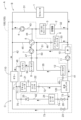
- FIG. 1 is a circuit configuration diagram of a cooling system having a manifold according to a first embodiment.
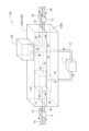
- FIG. 2 is a schematic configuration diagram of a manifold. It is a figure showing the relationship between the first internal refrigerant path and the eighth internal flow path concerning a 1st embodiment, and other flow paths.
- FIG. 7 is a diagram showing a flow path configuration of a manifold according to a second embodiment.
- FIG. 7 is a diagram showing a flow path configuration of a manifold according to a modification of the second embodiment.
- FIG. 7 is a diagram showing a flow path configuration of a manifold according to another modification of the second embodiment. It is a sectional view showing a method of fixing a chiller to a channel housing according to a third embodiment.
- FIG. 3 is a schematic configuration diagram of a manifold according to a fourth embodiment. It is a sectional view showing the composition of the chiller in the channel housing concerning a 4th embodiment. It is a circuit block diagram of the cooling system which has a manifold concerning a 5th embodiment. It is a schematic block diagram of the manifold based on 5th Embodiment. It is a figure showing the relationship between the 2nd refrigerant flow path and the 4th refrigerant flow path concerning a 5th embodiment, and other flow paths. It is a Mollier diagram showing a thermal cycle. It is a figure which shows the high temperature flow path and low temperature flow path based on other embodiment. It is a figure which shows the high temperature flow path and low temperature flow path based on other embodiment. It is a figure which shows the high temperature flow path and low temperature flow path based on other embodiment.
- a cooling system A including a manifold 100 is roughly divided into a cooling water circuit B and a refrigerant circuit C.
- cooling water such as antifreeze or long-life coolant containing ethylene glycol as a main component (an example of a second cooling fluid or cooling liquid) flows
- refrigerant circuit C cooling water such as antifreeze or long-life coolant containing ethylene glycol as a main component flows
- a cooling water such as a long-life coolant containing ethylene glycol as a main component flows.
- a refrigerant (an example of the first cooling fluid) flows.
- the manifold 100 includes a flow passage housing 105, a chiller 110 (an example of an evaporator), a water-cooled condenser 120 (an example of a condenser), a first electric pump 4, a rotary valve 5 consisting of a four-way valve, a second electric pump 7, and a three-way valve. It has auxiliary machinery including a switching valve 10 consisting of a valve, a third electric pump 11, a first expansion valve 23, and a second expansion valve 26. In FIG. 1, the auxiliary equipment is depicted as being inside the channel housing 105, but as shown in FIG. 2, it is actually attached to the outer surface of the channel housing 105. FIG.
- the channel housing 105 is formed of a metal material with high thermal conductivity including aluminum, and the channels constituting the cooling water circuit B and the refrigerant circuit C are formed by directly drilling holes in the channel housing 105. has been done.
- a coolant such as antifreeze or long-life coolant containing ethylene glycol as a main component is used. Good too.
- the refrigerant may be a refrigerant such as hydrofluoroolefin (HFO).
- Cooling water circuit B is a flow path on the right side of chiller 110 and water-cooled condenser 120 in FIG.
- the cooling water circuit B has a first external flow path 31 outside the flow path housing 105.
- the first external channel 31 includes a first internal channel 41 (an example of a second channel, a cooling channel) and a second internal channel 42 (an example of a second channel, a cooling channel) formed inside the channel housing 105. (an example of a flow path).
- the radiator 1 is arranged in the middle of the first external flow path 31.
- the cooling water flows through the second internal flow path 42 , the first external flow path 31 , the radiator 1 , the first external flow path 31 , and the first internal flow path 41 in this order.
- the upstream side and the downstream side with respect to the cooling water circulation direction in the cooling water circuit B will also be simply referred to as the upstream side and the downstream side.
- a second external flow path 32 and a third external flow path 33 are branched from the first external flow path 31 on the downstream side of the radiator 1 and the upstream side of the first internal flow path 41 in the first external flow path 31. .
- the second external flow path 32 is connected to a third internal flow path 43 formed inside the flow path housing 105 on the downstream side.
- the third internal flow path 43 is connected to the second internal flow path 42 on the downstream side.
- the cooling water branched from the first external flow path 31 to the second external flow path 32 flows through the second external flow path 32, cools the charger 2 and the DC-DC converter 3, and cools the third internal flow path 43. flows into.
- the cooling water is pressurized by the first electric pump 4 in the third internal flow path 43 and then flows into the second internal flow path 42 .
- a fourth internal flow path 44 branches from the third internal flow path 43 on the upstream side of the first electric pump 4 in the third internal flow path 43 .
- the fourth internal flow path 44 is connected to the fifth internal flow path 45 via the rotary valve 5.
- the downstream side of the fifth internal flow path 45 is connected to the second internal flow path 42 .
- the third external flow path 33 is connected to a sixth internal flow path 46 formed inside the flow path housing 105 on the downstream side.
- the sixth internal flow path 46 is connected to the seventh internal flow path 47 via the rotary valve 5.
- a second electric pump 7 is disposed in the middle of the seventh internal flow path 47 .
- the cooling water branched from the first external flow path 31 to the third external flow path 33 flows through the third external flow path 33, cools the e-axle inverter 6, and flows into the sixth internal flow path 46. In the state shown in FIG. 1, the cooling water is pressurized by the second electric pump 7 in the seventh internal flow path 47 via the rotary valve 5, and then flows out of the flow path housing 105.
- the e-axle inverter 6 is a unit in which a rotating electric machine, a speed reducer, and a differential gear mechanism are housed in a housing, and the inverter is provided integrally with the unit. Note that by rotating the rotary valve 5, the fourth internal flow path 44 and the sixth internal flow path 46 can be connected, and the fifth internal flow path 45 and the seventh internal flow path 47 can be connected.
- the seventh internal flow path 47 is connected to the fourth external flow path 34 outside the flow path housing 105.
- the fourth external flow path 34 is connected to an eighth internal flow path 48 (an example of a second flow path, a cooling flow path) formed inside the flow path housing 105 on the downstream side.
- the cooling water flowing out from the seventh internal flow path 47 flows through the fourth external flow path 34, is cooled by the first heater core 8, is then heated by cooling the battery 9, and flows into the eighth internal flow path 48. do.
- the eighth internal flow path 48 is connected to the chiller 110 on the downstream side.
- the downstream side of chiller 110 is connected to second internal flow path 42 .
- the cooling water flowing through the eighth internal flow path 48 flows into the chiller 110, and in the chiller 110, heat is generated in the mist refrigerant flowing from the third internal refrigerant path 73 (a first flow path, an example of a refrigerant flow path), which will be described later. After being deprived of water and cooled, it flows through the second internal flow path 42. The cooling water flowing through the second internal channel 42 flows into the first external channel 31 connected to the outside of the channel housing 105 .
- the first internal flow path 41 connected to the first external flow path 31 is connected to the water-cooled condenser 120 on the downstream side. Moreover, the switching valve 10 and the third electric pump 11 are arranged in this order in the middle of the first internal flow path 41.
- the downstream side of the water-cooled condenser 120 is connected to a ninth internal flow path 49 (a second flow path, an example of a cooling flow path).
- the cooling water that has flowed into the first internal flow path 41 is pressurized by the third electric pump 11 and flows into the water-cooled condenser 120.
- the refrigerant After being heated by removing heat from the refrigerant in a high-temperature compressed gas state that has flowed in through the refrigerant (one example of the refrigerant passage), the refrigerant flows through the ninth internal passage 49 and flows out of the passage housing 105 .
- the ninth internal flow path 49 is connected to the fifth external flow path 35 outside the flow path housing 105.
- the fifth external flow path 35 is connected to a tenth internal flow path 50 formed inside the flow path housing 105 on the downstream side.
- the tenth internal flow path 50 is connected to the sixth internal flow path 46 on the downstream side.
- the cooling water flowing out from the ninth internal flow path 49 flows through the fifth external flow path 35, is cooled by the second heater core 12, and flows into the tenth internal flow path 50.
- the cooling water flowing through the tenth internal flow path 50 flows into the sixth internal flow path 46 .
- the switching valve 10 disposed in the first internal flow path 41 switches the flow direction of the cooling water between the first internal flow path 41 and the eleventh internal flow path 51 formed inside the flow path housing 105.
- the eleventh internal flow path 51 is connected to the tenth internal flow path 50 on the downstream side.
- Refrigerant circuit C is a flow path on the left side of chiller 110 and water-cooled condenser 120 in FIG.
- the refrigerant circuit C is formed inside the channel housing 105, and a refrigerant flows therethrough.
- a first internal refrigerant path 71 (first internal refrigerant path 71) is provided on the downstream side in the refrigerant flow direction (hereinafter, the upstream side and downstream side in the refrigerant circuit C in the refrigerant flow direction are also simply referred to as the upstream side and the downstream side). (an example of a refrigerant flow path).
- the first internal refrigerant passage 71 is connected to a first external refrigerant passage 61 formed outside the passage housing 105 .
- An accumulator 21 and a compressor 22 are arranged in this order in the middle of the first external refrigerant path 61.
- the first external refrigerant passage 61 is connected to a second internal refrigerant passage 72 formed inside the passage housing 105 on the downstream side.
- the second internal refrigerant path 72 is connected to the water-cooled condenser 120 on the downstream side.
- the downstream side of the water-cooled condenser 120 is connected to a third internal refrigerant passage 73 formed inside the passage housing 105.
- the third internal refrigerant path 73 is connected to the chiller 110 via the first expansion valve 23 disposed in the middle.
- the water-cooled condenser 120 is installed at a position on the upstream side with respect to the refrigerant flow direction in the third internal refrigerant path 73, and the chiller 110 is installed at a position on the downstream side with respect to the refrigerant flow direction. is installed.
- a fourth internal refrigerant path 74 branches from the third internal refrigerant path 73 on the upstream side of the first expansion valve 23 in the third internal refrigerant path 73 .
- a second expansion valve 26 is disposed in the middle of the fourth internal refrigerant path 74.
- the fourth internal refrigerant passage 74 is connected to the second external refrigerant passage 62 formed outside the passage housing 105.
- An evaporator 24 and a check valve 25 are arranged in this order in the middle of the second external refrigerant path 62.
- the second external refrigerant passage 62 is connected to a fifth internal refrigerant passage 75 formed inside the passage housing 105.
- the fifth internal refrigerant path 75 is connected to the first internal refrigerant path 71 on the downstream side.
- the refrigerant is condensed and liquefied in the water-cooled condenser 120 by having heat removed by the cooling water flowing in from the first internal flow path 41 .
- the liquefied refrigerant used for cooling the inside of the car exits the water-cooled condenser 120, flows through the third internal refrigerant path 73 and the fourth internal refrigerant path 74, and is expanded by the second expansion valve 26 to achieve low temperature and low pressure. After being atomized, it flows out of the passage housing 105, flows through the second external refrigerant passage 62, and is sent to the evaporator 24. The atomized refrigerant absorbs heat from the air introduced from the outside in the evaporator 24 and evaporates. Conversely, the air is cooled by the refrigerant removing heat and is sent into the car as cold air.
- the evaporated and vaporized refrigerant passes through the check valve 25 disposed in the second external refrigerant path 62, flows into the fifth internal refrigerant path 75, and flows from the first internal refrigerant path 71 to the outside of the flow path housing 105. leak. Then, the vaporized refrigerant flows through the first external refrigerant path 61 and is sent to the accumulator 21 . In the accumulator 21, when the vaporized refrigerant contains liquid, the liquid is separated from the vaporized refrigerant. Thereafter, the vaporized refrigerant flows through the first external refrigerant path 61, returns to the compressor 22, and is compressed again to become a high-temperature compressed gas.
- the refrigerant that is not used for cooling the inside of the vehicle exits the water-cooled condenser 120, flows through the third internal refrigerant path 73, and is expanded in the first expansion valve 23 to form a low-temperature, low-pressure mist. After that, it is sent to the chiller 110.
- the atomized refrigerant is evaporated in the chiller 110 by taking heat from the cooling water flowing in from the eighth internal flow path 48 .
- the evaporated and vaporized refrigerant flows out of the first internal refrigerant path 71 to the outside of the flow path housing 105 .
- the vaporized refrigerant flows through the first external refrigerant path 61 and is sent to the accumulator 21 . Since the second external refrigerant path 62 includes the check valve 25, the refrigerant does not flow into the evaporator 24. In the accumulator 21, when the vaporized refrigerant contains liquid, the liquid refrigerant is separated. Thereafter, the vaporized refrigerant flows through the first external refrigerant path 61, returns to the compressor 22, and is compressed again to become a high-temperature compressed gas.
- cooling water and refrigerant are heat exchangers, but in this embodiment, the flow path of the cooling water circuit B and the flow path of the refrigerant circuit C are By placing these in close proximity, heat exchange is performed not only in the chiller 110 and the water-cooled condenser 120 but also between the channels.
- the arrangement of the channels connected to the chiller 110 is as shown in FIG.
- the first internal refrigerant passage 71 of the refrigerant circuit C flowing out from the chiller 110 is arranged in parallel and close to the second internal passage 42 of the cooling water circuit B flowing out from the chiller 110 and the first internal refrigerant passage 71 of the refrigerant circuit C flowing into the chiller 110.
- the third internal refrigerant passage 73 is arranged parallel to and adjacent to the third internal refrigerant passage 73.
- the eighth internal passage 48 and the first internal refrigerant passage 71 exchange heat at a location formed in an L-shape, and the second internal passage 42 and the third internal refrigerant passage 73 exchange heat.
- Heat exchange is performed at the linearly formed locations. With this configuration, heat exchange is performed not only between the chiller 110 but also between the cooling water flowing through the eighth internal flow path 48 and the refrigerant flowing through the first internal refrigerant path 71. Heat exchange is also performed between the cooling water flowing through the flow path 42 and the refrigerant flowing through the third internal refrigerant path 73. In this way, heat exchange is also performed between the internal flow path outside the chiller 110 and the internal refrigerant path, so even if a small chiller 110 is used, necessary and sufficient cooling performance can be obtained.
- the arrangement of the flow passages connected to the water-cooled condenser 120 is specifically as shown in FIG. 41 and the third internal refrigerant path 73 of the refrigerant circuit C that flows out from the water-cooled condenser 120 are arranged in parallel and close to each other, and the ninth internal flow path 49 of the cooling water circuit B that flows out of the water-cooled condenser 120 and the water-cooled condenser 120.
- the second internal refrigerant path 72 of the refrigerant circuit C flowing into the refrigerant circuit C is arranged parallel to and adjacent to the second internal refrigerant path 72 of the refrigerant circuit C.
- the direction of flow of the cooling water flowing through the first internal flow path 41 and the flow direction of the refrigerant flowing through the third internal flow path 73 are reversed, and the flow direction of the cooling water flowing through the ninth internal flow path 49 is reversed.
- the direction is opposite to the direction of flow of the refrigerant flowing through the second internal refrigerant path 72.
- the first internal flow path 41 and the third internal refrigerant path 73 exchange heat at a location formed in a straight line
- the ninth internal flow path 49 and the second internal refrigerant path 72 Heat exchange is performed at the location formed in the shape of a letter.
- heat exchange is performed not only between the water-cooled condenser 120 but also between the cooling water flowing through the first internal flow path 41 and the refrigerant flowing through the third internal refrigerant path 73. Heat exchange is also performed between the cooling water flowing through the internal flow path 49 and the refrigerant flowing through the second internal refrigerant path 72. In this way, heat exchange is also performed between the internal flow path outside the water-cooled condenser 120 and the internal refrigerant path, so even if a small-sized water-cooled condenser 120 is used, necessary and sufficient cooling performance can be obtained.
- FIG. 3 is a diagram showing the relationship between the first internal refrigerant path 71 and the eighth internal flow path 48 and other flow paths according to the present embodiment.
- a first internal refrigerant path 71 through which refrigerant flows out of the chiller 110 and an eighth internal path 48 through which cooling water flows into the chiller 110 are connected to the flow path housing 105. They are provided at intervals shorter than the intervals between other channels provided in the flow channels.
- the first internal refrigerant path 71 is a refrigerant flow path through which refrigerant flows from the chiller 110 to the accumulator 21 .
- the eighth internal flow path 48 is a cooling flow path through which cooling water flows from the battery 9 to the chiller 110.
- the other channels provided in the channel housing 105 include a first internal channel 41 through which the cooling water flowing into the water-cooled condenser 120 flows, a ninth internal channel 49 through which the cooling water flowing out from the water-cooled condenser 120 flows; This corresponds to the third internal refrigerant path 73 through which the refrigerant flowing out from the water-cooled condenser 120 flows, and the second internal refrigerant path 72 through which the refrigerant flowing into the water-cooled condenser 120 flows.
- the first internal refrigerant path 71 and the eighth internal refrigerant path 48 are defined by the distance between the first internal refrigerant path 41 and the third internal refrigerant path 73, and the distance between the ninth internal refrigerant path 49 and the second internal refrigerant path 72. provided at intervals shorter than the interval. That is, the eighth internal flow path 48 is configured to be closer to the first internal refrigerant path 71 than the first internal flow path 41 , the second internal flow path 42 , and the ninth internal flow path 49 .
- the ninth internal flow path 49 is located closer to the second internal refrigerant path 72 than the first internal flow path 41, the second internal flow path 42, and the eighth internal flow path 48. and the first internal flow path 41 is configured to be closer to the third internal refrigerant path 73 than the second internal flow path 42, the eighth internal flow path 48, and the ninth internal flow path 49. suitable. Further, in the vicinity of the chiller 110, the second internal flow path 42 is made closer to the third internal refrigerant path 73 than the first internal flow path 41, the eighth internal flow path 48, and the ninth internal flow path 49. It is preferable to configure the
- the eighth internal flow path 48 and the first internal refrigerant path 71, the second internal flow path 42 and the third internal refrigerant path 73, and the first internal refrigerant path 71 are arranged in parallel and close to each other in the flow path housing 105.
- the shapes of the passage 41 and the third internal refrigerant passage 73, and the ninth internal flow passage 49 and the second internal refrigerant passage 72 are different from those in the first embodiment. Since the other configurations are the same as those in the first embodiment, detailed explanations of the similar configurations will be omitted.
- the eighth internal flow path 48, the portion of the second internal flow path 42 that is arranged parallel to and close to the third internal refrigerant path 73, and the third internal refrigerant path 73 of the first internal flow path 41 are collectively referred to as a parallel internal flow path 81.
- the portions of the first internal refrigerant passage 71 and the third internal refrigerant passage 73 that are arranged parallel to and close to the second internal passage 42 and the first internal passage 41, and the second internal refrigerant passage 72 are They are collectively referred to as parallel internal refrigerant passages 82.
- a plurality of closed internal channels 83 branch from the parallel internal channel 81 in a direction perpendicular to the extending direction of the channel.
- a plurality of closed internal refrigerant passages 84 are branched from the parallel internal refrigerant passage 82 in a direction perpendicular to the extending direction of the passage.
- the closed internal flow path 83 has a closed end and extends in a direction approaching the parallel internal refrigerant path 82 .
- the closed internal refrigerant passage 84 has a closed end and extends in a direction approaching the parallel internal flow passage 81 .
- the closed internal flow path 83 and the closed internal refrigerant path 84 are arranged in parallel and close to each other. Further, the closed internal flow path 83 and the closed internal refrigerant path 84 both have the same cross-sectional shape as the parallel internal flow path 81 and the parallel internal refrigerant path 82, and have the same flow path cross-sectional area. The flow direction of the cooling water flowing through the parallel internal flow path 81 and the flow direction of the refrigerant flowing through the parallel internal refrigerant path 82 are opposite to each other.
- the manifold 100 has such a configuration, heat exchange between the cooling water and the refrigerant is performed not only between the parallel internal flow path 81 and the parallel internal refrigerant path 82, but also between the closed internal flow path 83 and the closed internal refrigerant path. This can also be done between the refrigerant path 84.
- a water-cooled condenser 120 that is smaller than that of the first embodiment is used. It is possible to obtain the necessary and sufficient cooling performance.
- the number of the closed internal flow path 83 and the closed internal refrigerant path 84 may be one instead of a plurality (the same applies to the following modifications).
- the flow path housing 105 may be constructed by joining two housings (not shown). good.
- grooves constituting a parallel internal flow path 81, a parallel internal refrigerant path 82, a closed internal flow path 83, and a closed internal refrigerant path 84 are formed on each of the joint surfaces of the two housings, and then the two housings are joined.
- a parallel internal flow path 81, a parallel internal refrigerant path 82, a closed internal flow path 83, and a closed internal refrigerant path 84 can be formed in the flow path housing 105.
- the extending direction of the closed internal refrigerant passage 84 with respect to the parallel internal refrigerant passage 82 is not perpendicular, but extends in the direction of a branching angle ⁇ that is an acute angle with respect to the flow direction of the refrigerant.
- the closed internal flow path 83 branches at an acute angle to the cooling water flow direction of the parallel internal flow path 81 at a branching angle ⁇ , and the closed internal refrigerant path 84 branches at an acute angle to the refrigerant flow direction of the parallel internal refrigerant path 82. Since the closed internal flow path 83 and the closed internal refrigerant path 84 are arranged in parallel and close to each other because they are branched in the direction at a branching angle ⁇ . With this configuration, even if the distance between the parallel internal flow path 81 and the parallel internal refrigerant path 82 is the same as in the second embodiment, the lengths of the closed internal flow path 83 and the closed internal refrigerant path 84 can be reduced. It can be made longer than the second embodiment.
- the closed internal flow path 83 and the closed internal refrigerant path 84 both have a right triangular shape in plan view, and the hypotenuse of the right triangle and the adjacent side thereof are It is configured.
- the other adjacent side is a part of the parallel internal flow path 81.
- a portion of the closed internal flow path 83 corresponding to the hypotenuse of the right triangle extends in the direction of a branching angle ⁇ that is an acute angle with respect to the cooling water flow direction, and a portion corresponding to the adjacent side extends to the direction of the cooling water flow. perpendicular to the direction.
- a portion of the closed internal refrigerant passage 84 corresponding to the hypotenuse of the right triangle extends in the direction of a branching angle ⁇ that is an acute angle with respect to the refrigerant flow direction, and a portion corresponding to the adjacent side extends toward the refrigerant flow direction. perpendicular to the direction. That is, also in this modification, the closed internal flow path 83 and the closed internal refrigerant path 84 are arranged in parallel and close to each other at locations corresponding to oblique sides and locations corresponding to adjacent sides.
- a portion corresponding to the oblique side of the closed internal flow path 83 branches at an acute angle to the cooling water flow direction of the parallel internal flow path 81 at a branching angle ⁇ , and a portion corresponding to the oblique side of the closed internal refrigerant path 84 branches within the parallel internal flow path 81. Since the refrigerant passage 82 is branched at an acute angle with respect to the flow direction of the refrigerant at a branching angle ⁇ , the locations corresponding to the oblique sides of the closed internal flow passage 83 and the closed internal refrigerant passage 84 and the locations corresponding to the adjacent sides They are all arranged in parallel and close to each other.
- the closed internal flow path 83 and the closed internal refrigerant path 84 are configured in this manner.
- the lengths of the flow path 83 and the closed internal refrigerant path 84 (the sum of the length of the oblique side and the length of the adjacent side in plan view) can be made longer than in the second embodiment.
- heat exchange between the closed internal flow path 83 and the closed internal refrigerant path 84 can be performed more efficiently than in the second embodiment, so even if a smaller water-cooled condenser 120 is used.
- locations corresponding to the oblique sides of the closed internal flow path 83 and the closed internal refrigerant path 84 are branched at an acute angle with respect to the flow direction of cooling water and refrigerant. Since the locations corresponding to the adjacent sides are branched in a direction perpendicular to the flow direction of the cooling water and refrigerant, cooling is achieved when the cooling water and refrigerant flow into and out of the closed internal flow path 83 and the closed internal refrigerant path 84. Pressure loss of water and refrigerant can be kept to a minimum.
- the flow direction of the cooling water and the refrigerant that exchange heat within the channel housing 105 is opposite, but the flow direction may be the same.
- the chiller 110 may be provided on the upstream side
- the water-cooled condenser 120 may be provided on the downstream side.
- the flow path for heat exchange within the flow path housing 105 is linear or L-shaped, but is not limited to this. do not have.
- the chiller 110 and the water-cooled condenser 120 can be made more compact by making the flow path for heat exchange as long as possible. Further, the flow path that performs heat exchange may have a form in which heat is exchanged using a plate member.
- a cooling system A including a manifold 100 according to the third embodiment is similar to the cooling system A according to the first embodiment shown in FIG. Further, the schematic configuration of the manifold 100 is also the same as that in FIG. 2.
- the chiller 110 is fixed to the passage housing 105 by being directly connected to the third internal refrigerant passage 73, the first internal refrigerant passage 71, the eighth internal passage 48, and the second internal passage 42.
- the chiller 110 has a refrigerant inlet 111 through which the refrigerant flows, a refrigerant outlet 112 through which the refrigerant flows out, a cooling water inlet 113 (an example of a "coolant inlet”) through which the cooling water flows, and a cooling water flow through which the cooling water flows out. It has an outlet 114 (an example of a "coolant outlet").
- the third internal refrigerant passage 73 and the refrigerant inlet 111, the first internal refrigerant passage 71 and the refrigerant outlet 112, the eighth internal passage 48 and the cooling water inlet 113, and the second internal passage 42 and the cooling water outlet 114. are joined by brazing using a brazing material 116.
- Brazing is characterized in that the shapes and materials of each housing are less likely to change and the bonding strength is high by joining near the melting temperature of the brazing filler metal 116, which has a lower melting point than that of the channel housing 105 and the housing of the chiller 110. Furthermore, since the joining is performed by filling the brazing material 116, the joint location is excellent in airtightness and liquidtightness.
- the chiller was fixed to the channel housing 105 with bolts, etc., which required multiple bolts, piping to connect the channel and the heat exchanger, and sealing material to prevent leakage of refrigerant and cooling water.
- the number of parts and man-hours required to fix the chiller increased, and the volume of the chiller also increased.
- the chiller 110 can be fixed to the channel housing 105 without bolts (high bonding strength and small size) by joining the channel and the inlet and outlet of the chiller 110 with brazing. ), communication between the flow path and the chiller 110 (no piping required), and ensuring airtightness and watertightness of the joint (no sealing material required) can be achieved at the same time. Therefore, by reducing the number of parts and man-hours, it is possible to realize a small and low-cost manifold 100.
- the flow path housing 105 of this embodiment is constructed by joining an upper housing 105a and a lower housing 105b. As shown in FIG. 2, the third internal refrigerant passage 73, the first internal refrigerant passage 71, the eighth internal passage 48, and the second internal passage 42 are connected to each other from the interface between the upper housing 105a and the lower housing 105b. It passes through the upper housing 105a. After positioning the inlet and outlet of the chiller 110 in these passing passages, the third internal refrigerant passage 73 and the refrigerant inlet 111, the first internal refrigerant passage 71 and the refrigerant outlet 112, and the eighth internal refrigerant passage 73 and the refrigerant outlet 112 are arranged.
- a brazing filler metal 116 is applied to each boundary between the channel 48 and the cooling water inlet 113, and between the second internal flow channel 42 and the cooling water outlet 114. Then, each of the third internal refrigerant passage 73, first internal refrigerant passage 71, eighth internal passage 48, and second internal passage 42 is brazed from the lower surface of the upper housing 105a (interface with the lower housing 105b). Insert the tool and perform brazing. At this time, the thinner the upper housing 105a is, the easier it is to insert a brazing tool, so that brazing can be performed more easily.
- a manifold 100 Next, a manifold 100 according to a fourth embodiment will be described using FIGS. 8 and 9.
- the chiller 110 is arranged inside the channel housing 105. Specifically, a flow path having a heat exchange function for the chiller 110 is formed in the flow path housing 105 .
- the other configurations are similar to those of the third embodiment. Therefore, in the description of this embodiment, the same reference numerals are given to the parts having the same configuration as in the third embodiment, and detailed explanation regarding the same configuration will be omitted.
- the flow path housing 105 is constructed by joining an upper housing 105a and a lower housing 105b.
- a heat exchange channel 117 (an example of a laminated channel) is formed inside the channel housing 105 from the upper housing 105a to the lower housing 105b.
- the heat exchange flow path 117 is configured by alternately stacking a plurality of heat exchange refrigerant flow paths 117a (an example of a laminated flow path) and a plurality of heat exchange cooling water flow paths 117b (an example of a lamination flow path).
- the plurality of heat exchange cooling water channels 117b are connected to the eighth internal channel 48 and the second internal channel 42, respectively.
- the plurality of heat exchange refrigerant channels 117a are depicted as independent channels, but in reality they are connected to the third internal refrigerant channel 73 and the first internal refrigerant channel 71, respectively. has been done.
- a flow path wall 118 that partitions the heat exchange refrigerant flow path 117a and the heat exchange cooling water flow path 117b is supported by the flow path housing 105.
- the manifold 100 can be made smaller compared to the case where the chiller 110 is externally attached to the channel housing 105.
- the chiller 110 is fixed to the channel housing 105 by brazing, but the present invention is not limited to this. If the joint strength, airtightness, liquidtightness, etc. of the chiller 110 to the channel housing 105 can be ensured, any method such as welding may be used instead of brazing.
- connection and fixation of the chiller 110 to the channel housing 105 have been described, but the same applies to the water-cooled condenser 120 and other heat exchangers. Applicable to
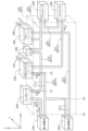
- FIG. 10 is a diagram showing a circuit configuration of a cooling system 300 including the manifold 201 of this embodiment.
- FIG. 11 is a diagram showing a schematic configuration of the manifold 201 of this embodiment.
- the manifold 201 includes a refrigerant circuit through which a refrigerant such as hydrofluorocarbon (HFC) or hydrofluoroolefin (HFO) flows.
- HFC hydrofluorocarbon
- HFO hydrofluoroolefin
- the manifold 201 includes a channel housing 210.
- the flow path housing 210 is formed using a metal material including a material with high thermal conductivity such as aluminum, and has a first refrigerant flow path ("first flow") formed by drilling holes in such metal material.
- first flow a first refrigerant flow path
- second refrigerant flow path an example of a “first flow path”
- third refrigerant flow path an example of a “second flow path”
- a fourth refrigerant flow path an example of a “second flow path” 211; 214 (an example of a flow path).
- An on-off valve (not shown) is provided upstream of the first expansion valve 235, which will be described later, in the third refrigerant flow path 213.
- the on-off valve is opened when the vehicle uses indoor cooling, and is closed when the indoor cooling is not used.
- the flow passage housing 210 includes an accumulator 220, a compressor (an example of a “compressor”) 225, a water-cooled condenser (an example of a “condenser”) 230, a first expansion valve (an example of a “condenser”), and a first expansion valve (an example of a “condenser”).
- An example of an “expansion valve”) 235, a second expansion valve 240, an evaporator (an example of an "evaporator”) 245, a check valve 250, and a chiller (an example of an "evaporator”) 255 are provided on the outside.
- the water-cooled condenser 230, the evaporator 245, the check valve 250, and the chiller 255 are integrated with the channel housing 210.
- the auxiliary equipment that is integrated with the flow path housing 210 is arbitrary and is not particularly limited.
- the first refrigerant flow path 211 is a flow path that allows a refrigerant (an example of a "first cooling fluid") to flow between the compressor 225 and the water-cooled condenser 230.
- the second refrigerant flow path 212 is a flow path that allows a refrigerant (an example of a "first cooling fluid") to flow between the water-cooled condenser 230 and the first expansion valve 235 and/or the second expansion valve 240.
- the third refrigerant flow path 213 is a flow path that allows refrigerant (an example of a "second cooling fluid”) to flow between the first expansion valve 235 and the second expansion valve 240 and the evaporator 245 and chiller 255, respectively.
- the fourth refrigerant flow path 214 is a flow path that allows refrigerant (an example of a "second cooling fluid”) to flow between the evaporator 245 and/or chiller 255 and the compressor 225.
- the accumulator 220 is a gas-liquid separator that stores liquid refrigerant and performs gas-liquid separation of the refrigerant.
- the gaseous refrigerant separated by the accumulator 220 flows through the fourth refrigerant flow path 214 and is sent to the compressor 225.
- the compressor 225 compresses the gaseous refrigerant from the accumulator 220. As a result, the pressure of the refrigerant increases and the temperature (referred to as "T1") increases.
- T1 the temperature
- the high-temperature, high-pressure, gaseous refrigerant is sent to the water-cooled condenser 230 via the first refrigerant flow path 211 .
- Cooling water flows through the water-cooled condenser 230 through a cooling water flow path 231 that is different from the first refrigerant flow path 211 and the second refrigerant flow path 212.
- the heat of the high-temperature, high-pressure gaseous refrigerant sent to the water-cooled condenser 230 is absorbed by the cooling water.
- the high-temperature, high-pressure gaseous refrigerant is condensed and becomes a medium-temperature, high-pressure liquid refrigerant. That is, the temperature of the refrigerant decreases from T1 to T2.
- the medium-temperature, high-pressure liquid refrigerant is sent to the first expansion valve 235 and/or the second expansion valve 240 via the second refrigerant flow path 212 .
- the first expansion valve 235 has a flow path area that is rapidly narrower than that of the second refrigerant flow path 212, and is configured so that only a small amount of refrigerant flows therethrough.
- the pressure of the refrigerant decreases, and as the pressure decreases, the temperature of the refrigerant decreases, and the gaseous refrigerant mixes with the liquid refrigerant.
- the low-temperature, low-pressure refrigerant is sent to the evaporator 245 via the third refrigerant flow path 213.
- T3 the temperature of the refrigerant has decreased to T3.
- the evaporator 245 takes in outside air and exchanges heat between the outside air and the low-temperature, low-pressure refrigerant. As a result, the temperature of the refrigerant increases and changes to a gaseous refrigerant, which cools the outside air and is used for indoor cooling.
- the medium-temperature, low-pressure, gaseous refrigerant is sent to the accumulator 220 via the check valve 250 and the fourth refrigerant flow path 214 .
- the temperature of the refrigerant sent out from the evaporator 245 at this time is assumed to be T4.
- T4 is a temperature higher than T3 and lower than T2.
- Part or all of the refrigerant condensed by the water-cooled condenser 230 is branched from the second refrigerant flow path 212 and sent to the second expansion valve 240.
- the medium-temperature, high-pressure liquid refrigerant changes to a low-temperature, low-pressure refrigerant.
- This low-temperature, low-pressure refrigerant is sent to the chiller 255 via the third refrigerant flow path 213.
- the low-temperature, low-pressure refrigerant sent to the chiller 255 cools the cooling water and gives it heat. This changes the refrigerant into a gaseous refrigerant with medium temperature and low pressure.
- the refrigerant changed into a gaseous state is sent to the accumulator 220 via the fourth refrigerant flow path 214.
- the refrigerant sent from the chiller 255 through the fourth refrigerant flow path 214 does not flow to the evaporator 245 due to the check valve 250 .
- high temperature and high pressure refrigerant (refrigerant at temperature T1) is sent from the compressor 225 to the first refrigerant flow path 211, and medium temperature and high pressure refrigerant (refrigerant at temperature T2) is sent from the water cooling condenser 230 to the second refrigerant flow path 212. refrigerant) is pumped out.
- low-temperature, low-pressure refrigerant (refrigerant at temperature T3) is sent from the first expansion valve 235 to the third refrigerant flow path 213, and medium-temperature, low-pressure refrigerant is sent from the evaporator 245 and/or chiller 255 to the fourth refrigerant flow path 214.
- the temperature T2 of the refrigerant sent out to the second refrigerant flow path 212 is higher than the temperature T4 of the refrigerant sent out to the fourth refrigerant flow path 214. Therefore, in the manifold 201, the first refrigerant flow path 211 and the second refrigerant flow path 212 correspond to the high temperature flow path 201H, and the third refrigerant flow path 213 and the fourth refrigerant flow path 214 correspond to the low temperature flow path 201L.
- the flow path housing 210 is configured to exchange heat between the high temperature flow path 201H and the low temperature flow path 201L.
- heat exchange is performed between the second refrigerant flow path 212, which is the high temperature flow path 201H, and the fourth refrigerant flow path 214, which is the low temperature flow path 201L.
- the second refrigerant flow path 212 and the fourth refrigerant flow path 214 are provided in parallel to each other and close to each other in the flow path housing 210.
- the refrigerant flows through the second refrigerant flow path 212 from the water-cooled condenser 230 toward the first expansion valve 235 and/or the second expansion valve 240, and from the evaporator 245 to the accumulator 220 via the check valve 250.
- a fourth refrigerant flow path 214 through which the refrigerant flows is provided parallel to each other between X1 and X2 along the X direction. Further, in order to increase heat exchange efficiency, the interval Y1 in the Y direction orthogonal to the X direction is configured to be short.
- This interval Y1 is preferably set based on the machining accuracy when forming the second refrigerant flow path 212 and the fourth refrigerant flow path 214 by drilling (it is better to make them closer together). Further, the refrigerant flow path for heat exchange may be formed by a cut surface of the flow path housing 210.
- the refrigerant flows from X2 to X1 in the second refrigerant flow path 212, and the refrigerant flows from X1 to X2 in the fourth refrigerant flow path 214. Therefore, in this embodiment, the flow directions of the refrigerant in the high temperature flow path 201H and the low temperature flow path 201L are configured to be opposite to each other. As a result, the refrigerant flowing through the second refrigerant flow path 212 exchanges heat with the refrigerant flowing through the fourth refrigerant flow path 214, and the refrigerant flowing through the fourth refrigerant flow path 214 is transferred to the second refrigerant flow path 212.
- Heat exchange is performed between the refrigerant and the circulating refrigerant.
- the temperature of the refrigerant flowing through the high temperature flow path 201H gradually decreases as it flows through the high temperature flow path 201H in the first direction (from X2 to X1), and the temperature of the refrigerant flowing through the low temperature flow path 201L gradually decreases as it flows through the high temperature flow path 201H in the first direction (from X2 to X1).
- the temperature gradually increases as it flows in the second direction (from X1 to X2) opposite to the first direction.
- the temperature difference between the high temperature flow path 201H and the low temperature flow path 201L in the heat exchange area becomes equal, so that the heat exchange efficiency can be improved. Therefore, it becomes possible to efficiently exchange heat.
- a second refrigerant flow path 212 through which refrigerant flows from the water-cooled condenser 230 toward the second expansion valve 240 and a third refrigerant flow path through which refrigerant flows from the second expansion valve 240 toward the chiller 255 are provided.
- a path 213 is provided parallel to each other between X3 and X4 along the X direction.
- the distance Y2 in the Y direction perpendicular to the X direction is configured to be short. This interval Y2 is preferably set based on the machining accuracy when forming the second refrigerant flow path 212 and the third refrigerant flow path 213 by drilling (it is better to make them closer together).
- the refrigerant flow path for heat exchange may be formed by a cut surface of the flow path housing 210.
- the refrigerant flows from X4 to X3 in the second refrigerant flow path 212, and the refrigerant flows from X3 to X4 in the third refrigerant flow path 213. Therefore, also here, the flow directions of the refrigerant in the high temperature flow path 201H and the low temperature flow path 201L are configured to be opposite to each other. As a result, the refrigerant flowing through the second refrigerant flow path 212 exchanges heat with the refrigerant flowing through the third refrigerant flow path 213, and the refrigerant flowing through the third refrigerant flow path 213 is transferred to the second refrigerant flow path 212.
- Heat exchange is performed between the refrigerant and the circulating refrigerant.
- the temperature of the refrigerant flowing through the high temperature flow path 201H gradually decreases as it flows through the high temperature flow path 201H in the first direction (from X4 to X3), and the temperature of the refrigerant flowing through the low temperature flow path 201L becomes lower.
- the temperature gradually increases as it flows in the second direction (from X3 to X4) opposite to the first direction.
- the temperature difference between the high temperature flow path 201H and the low temperature flow path 201L in the heat exchange area becomes equal, so that the heat exchange efficiency can be improved. Therefore, it becomes possible to efficiently exchange heat.
- FIG. 12 is a diagram showing the relationship between the second refrigerant flow path 212 and the fourth refrigerant flow path 214 and other flow paths according to the present embodiment.
- a second refrigerant flow path 212 that allows refrigerant to flow between the water-cooled condenser 230 and the first expansion valve 235
- a fourth refrigerant flow path that allows the refrigerant to flow between the evaporator 255 and the compressor 225.
- the passages 214 are provided at intervals shorter than the intervals between other passages provided in the passage housing 210.
- the second refrigerant flow path 212 is a refrigerant flow path through which refrigerant flows from the water-cooled condenser 230 to the first expansion valve 235.
- the fourth refrigerant flow path 214 is a refrigerant flow path through which refrigerant flows from the evaporator 245 to the compressor 225 via the accumulator 220.
- the other flow paths provided in the flow path housing 210 include a first refrigerant flow path 211 through which refrigerant flows from the compressor 225 to the water-cooled condenser 230, and a third refrigerant flow path through which refrigerant flows from the first expansion valve 235 to the evaporator 245.
- the flow path 213 corresponds to this. Therefore, the second refrigerant flow path 212 and the fourth refrigerant flow path 214 are provided at a shorter interval than the distance between the first refrigerant flow path 211 and the third refrigerant flow path 213.
- the fourth refrigerant flow path 214 is configured to be closer to the second refrigerant flow path 212 than the first refrigerant flow path 211 and the third refrigerant flow path 213.
- FIG. 13 is a Mollier diagram showing the thermal cycle in the cooling system 300.
- the horizontal axis represents the specific enthalpy of the refrigerant
- the vertical axis represents the pressure of the refrigerant.
- the boundary line between the supercooled state and the wet steam state is the saturated liquid line L1
- the boundary line between the wet steam state and the superheated steam state is the saturated steam line L2.
- the boundary point between the saturated liquid line L1 and the saturated vapor line L2 corresponds to a critical point CP.
- the refrigerant When the refrigerant is pressurized (compressed) by the compressor 225, the specific enthalpy increases, and the medium temperature and low pressure gaseous refrigerant shown in FIG. 13(a) changes to the high temperature and high pressure state shown in FIG. 13(b). It becomes a gaseous refrigerant.
- the high-temperature, high-pressure refrigerant shown in FIG. 13(b) is sent to the water-cooled condenser 30, it is condensed and its specific enthalpy is reduced in an equal pressure state. As a result, the refrigerant becomes a medium-temperature, high-pressure liquid refrigerant as shown in FIG. 13(c).
- FIG. 13(c) expands in the first expansion valve 235, and its pressure decreases. Therefore, it becomes a low-temperature, low-pressure gas-liquid mixed refrigerant shown in FIG. 13(d).
- the low-temperature, low-pressure refrigerant shown in FIG. 13(d) is evaporated in the evaporator 245, and the specific enthalpy increases in an equal pressure state. As a result, the refrigerant becomes a medium-temperature, low-pressure gaseous refrigerant as shown in FIG. 13(a).
- the flow path housing 210 by performing heat exchange between the second refrigerant flow path 212, which is the high temperature flow path 201H, and the fourth refrigerant flow path 214, which is the low temperature flow path 201L,
- the refrigerant to be pressurized by the compressor 225 can be warmed in advance. Thereby, the specific enthalpy of the refrigerant before pressurization can be increased, and the refrigerant generated by the compressor 225 is compressed along the broken lines shown in (e) to (f).
- the refrigerant condensed in the water-cooled condenser 230 can be cooled in advance by heat exchange between the second refrigerant flow path 212, which is the high temperature flow path 201H, and the fourth refrigerant flow path 214, which is the low temperature flow path 201L. .
- the specific enthalpy of the refrigerant before being expanded by the first expansion valve 235 can be reduced, and the refrigerant expands in the first expansion valve 235 along the broken line shown from (g) to (h).
- the compressor 225 by performing heat exchange between the second refrigerant flow path 212, which is the high temperature flow path 201H, and the fourth refrigerant flow path 214, which is the low temperature flow path 201L, the compressor 225 The pressurized refrigerant becomes more superheated vapor, and the refrigerant sent to the first expansion valve 235 becomes more supercooled. Therefore, it is possible to improve the coefficient of performance with a compact configuration.
- heat exchange is performed between the second refrigerant flow path 212, which is the high temperature flow path 201H, and the fourth refrigerant flow path 214, which is the low temperature flow path 201L, in the flow path housing 210.
- the flow path housing 210 it is also possible to configure heat exchange between the first refrigerant flow path 211, which is the high temperature flow path 201H, and the third refrigerant flow path 213, which is the low temperature flow path 201L. .
- the configuration may be such that heat exchange is performed between the first refrigerant flow path 211, which is the high temperature flow path 201H, and the fourth refrigerant flow path 214, which is the low temperature flow path 201L, or the high temperature flow path 201H It may be configured such that heat exchange is performed between a certain second refrigerant flow path 212 and a third refrigerant flow path 213 that is the low temperature flow path 201L. Furthermore, heat exchange may be performed between the first refrigerant flow path 211 and the second refrigerant flow path 212, which are the high temperature flow path 201H, and the third refrigerant flow path 213, which is the low temperature flow path 201L.
- heat exchange may be performed between the first refrigerant flow path 211 and the second refrigerant flow path 212, which are the high temperature flow path 201H, and the fourth refrigerant flow path 214, which is the low temperature flow path 201L. good.
- heat exchange may be performed between the first refrigerant flow path 211, which is the high temperature flow path 201H, and the third refrigerant flow path 213 and the fourth refrigerant flow path 214, which are the low temperature flow path 201L.
- the second refrigerant flow path 212 which is the high temperature flow path 201H
- the third refrigerant flow path 213 and the fourth refrigerant flow path 214 which are the low temperature flow path 201L.
- the high temperature flow path 201H and the low temperature flow path 201L are provided parallel to each other and close to each other.
- the high temperature flow path 201H and the low temperature flow path 201L are They may be provided close to each other without being parallel to each other, or may be provided so that the high temperature flow path 201H and the low temperature flow path 201L intersect with each other.
- the shape in which the high temperature flow path 201H and the low temperature flow path 201L are provided parallel to each other and close to each other may be, for example, a meandering flow path, and is not particularly limited.
- the refrigerant flow directions in the high temperature flow path 201H and the low temperature flow path 201L are opposite to each other. There may be.
- the high temperature flow path 201H and the low temperature flow path 201L are shown extending along a predetermined direction (X direction).
- a comb-shaped portion 260 that protrudes from one side of the high temperature flow path 201H and the low temperature flow path 201L toward the other side may be formed in each of the high temperature flow path 201H and the low temperature flow path 201L.
- FIG. 14 shows a high temperature flow path 201H and a low temperature flow path 201L in which such a comb-like portion 260 is formed. As shown in FIG.
- the high-temperature flow path 201H is provided with a comb-teeth portion 260 (specifically, a comb-teeth portion 260H) that protrudes from the high-temperature flow path 201H toward the low-temperature flow path 201L.
- the low-temperature flow path 201L is provided with a comb-teeth portion 260 (specifically, a comb-teeth portion 260L) that protrudes from the low-temperature flow path 201L toward the high-temperature flow path 201H. As shown in FIG.
- the comb-teeth-shaped portion 260H and the comb-teeth-shaped portion 260L are configured such that the comb-teeth-shaped portion 260H is inserted between two comb-teeth-shaped portions 260L, and the comb-teeth-shaped portion 260L is It is configured to enter between two comb-like portions 260H.
- the area where the high temperature flow path 201H and the low temperature flow path 201L are close to each other can be increased, and heat exchange efficiency can be improved.
- the comb-like portions 260 are formed to protrude from the high temperature flow path 201H and the low temperature flow path 201L, respectively, along the direction perpendicular to the high temperature flow path 201H and the low temperature flow path 201L.
- the comb-teeth portion 260 may be configured to have an obtuse angle with respect to the orthogonal direction, or the comb-teeth portion 260 may protrude in an arc shape.
- the comb-teeth portion 260 may have a triangular shape in plan view.
- the side has an obtuse angle on the upstream side with respect to the flow direction of the refrigerant flowing through the high temperature flow path 201H and the low temperature flow path 201L. It may be configured in a triangular shape having sides perpendicular to the downstream side with respect to the flow direction.
- the downstream side may be configured to have an acute angle downstream with respect to the flow direction of the refrigerant flowing through the high temperature flow path 201H and the low temperature flow path 201L.
- the flow path in the flow path housing 210 is formed by drilling, it is also possible to form the flow path by, for example, casting or forging.
- the manifold 100, 201 has a flow path having first flow paths 71, 72, 73 through which the first cooling fluid flows and second flow paths 41, 42, 48, 49 through which the second cooling fluid flows.
- a first cooling fluid flowing through the first flow paths 71, 72, 73 and a second cooling fluid flowing through the second flow paths 41, 42, 48, 49 are provided. It is configured to exchange heat between the
- the first cooling fluid flows through the first flow paths 71, 72, 73 provided in the flow path housing 105, 210 of the manifold 100, 201, and the second cooling fluid flows through the second flow paths 41, 42, 48, 49.
- the second cooling fluid flows through the second flow paths 41, 42, 48, 49.
- the cooling of the first cooling fluid flowing through the first flow paths 71, 72, 73 and the heating of the second cooling fluid flowing through the second flow paths 41, 42, 48, 49 are performed using the flow path housing 105, 210. This can be done within the company. By performing heat exchange between fluids within the flow path housings 105, 210, it becomes possible to improve the coefficient of performance of the compressors 22, 225 and the expansion valves 26, 235, 240, for example. Therefore, it is possible to downsize or perform heat exchange without separately providing an internal heat exchanger that cools and heats the fluid, so it is possible to downsize the manifolds 100, 201.
- the first flow paths 71, 72, 73 are refrigerant flow paths through which the refrigerant as the first cooling fluid flows between the evaporator 110 and the condenser 120. It is preferable that the second flow paths 41, 42, 48, and 49 are cooling flow paths through which at least a cooling liquid as the second cooling fluid flows through the battery 9.
- a water-cooled condenser 120 as a condenser 120 for the refrigerant is attached to the flow path housing 105 at a position on the upstream side with respect to the flow direction of the refrigerant, It is preferable that a chiller 110 serving as an evaporator 110 for the refrigerant is installed at a position on the downstream side with respect to the flow direction of the refrigerant.
- the refrigerant condensed in the water-cooled condenser 120 is circulated and turned into a low-temperature coolant. Since heat can be applied, the refrigerant that could not be completely condensed in the water-cooled condenser 120 can also be condensed.
- the chiller 110 as the evaporator 110 at a downstream position with respect to the refrigerant flow direction, the refrigerant before flowing into the chiller 110 can be circulated to remove heat from the high-temperature coolant. This allows some of the refrigerant to evaporate before entering the chiller 110.
- the first flow path is the first refrigerant flow path 211 through which refrigerant as the first cooling fluid flows between the compressor 225 and the condenser 230, or the condenser. 230 and the expansion valve 235;
- the third refrigerant flow path 213 through which refrigerant as the second cooling fluid flows, or the fourth refrigerant flow path 214 through which refrigerant flows between the evaporators 245, 255 and the compressor 225 is preferable. .
- the refrigerant flowing through at least one of the first refrigerant flow path 211 and the second refrigerant flow path 212 is cooled, and the refrigerant flowing through at least one of the third refrigerant flow path 213 and the fourth refrigerant flow path 214 is cooled.
- Heating of the refrigerant flowing through the flow path housing 210 can be performed within the flow path housing 210.
- the first flow paths 71, 72, 73 are refrigerant flow paths through which the refrigerant as the first cooling fluid flows through the heat exchanger
- the second flow paths 41, 42 , 48, 49 are cooling channels through which a cooling liquid as a second cooling fluid flows through the heat exchanger
- the heat exchanger includes a refrigerant inlet 111 through which the refrigerant flows, a refrigerant outlet 112 through which the refrigerant flows out, It has a coolant inlet 113 through which the coolant flows in, and a coolant outlet 114 through which the coolant flows out.
- the heat exchanger is fixed to the channel housing 105 by joining the inlet 113 and the cooling channel and coolant outlet 114, respectively.
- the heat exchanger can be fixed to the flow passage housing 105 without using bolts or the like, so there is no need to provide a flange for attaching bolts or the like to the heat exchanger, and the heat exchanger can be made small. be converted into Thereby, it is possible to realize a small and low-cost manifold 100.
- the heat exchanger preferably has the laminated flow path 117.
- the first flow path 71, 72, 73 and the second flow path 41, 42, 48, 49 are provided close to each other. It is preferable if
- each of the first flow path and the second flow path has a protruding portion from one of the first flow path and the second flow path toward the other side. It is preferable that a comb-teeth-shaped portion 260 is formed.
- heat exchange between the first cooling fluid and the second cooling fluid can be performed not only between the first flow path and the second flow path but also in the comb-like portion 260.
- a comb-shaped portion 260 can increase the region (area) in which the first flow path and the second flow path are close to each other. Therefore, it becomes possible to further improve heat exchange efficiency. As a result, even if a smaller heat exchanger is used, sufficient cooling performance can be obtained.
- the manifold 201 described in (7) has a flow path that allows refrigerant to flow between the condenser 230 and the expansion valves 235, 240, and a flow path that allows the refrigerant to flow between the evaporator 245, 255 and the compressor 225. It is preferable that the flow paths are provided at intervals shorter than the intervals between other flow paths provided in the flow path housing 210.
- Heat exchange can be performed between the flow path for circulating refrigerant between the condenser 230 and the expansion valves 235, 240, and the flow path for circulating the refrigerant between the evaporator 245, 255 and the compressor 225.
- Heat exchange can be performed.
- the flow direction of the refrigerant flowing through the flow path between the condenser 230 and the expansion valves 235, 240, and the flow direction of the refrigerant flowing through the flow path between the evaporator 245, 255 and the compressor 225 are determined.
- the temperature difference between the flow path between the condenser 230 and the expansion valves 235, 240 and the flow path between the evaporator 245, 255 and the compressor 225 is equalized by making them opposite to each other (in opposite directions). Therefore, heat exchange efficiency can be increased. Therefore, it becomes possible to efficiently exchange heat.
- the manifold 100 described in (7) includes a refrigerant flow path through which a refrigerant as a first cooling fluid flows out of the evaporator 110 and a cooling fluid as a second cooling fluid flowing into the evaporator 110. It is preferable that the cooling channels through which the cooling channels flow are provided at shorter intervals than the intervals between other channels provided in the channel housing 105.
- heat exchange can be performed between the refrigerant flowing through the refrigerant flow path from the evaporator 110 and the coolant flowing through the cooling flow path to the evaporator 110. Thereby, even if a small-sized evaporator 110 is used, sufficient cooling performance can be obtained.
- the technology according to the present disclosure can be used for manifolds.
- [First embodiment] 9 Battery, 41: First internal flow path (second flow path, cooling flow path, cooling pipe), 42: Second internal flow path (second flow path, cooling flow path, cooling pipe), 48: Eighth Internal flow path (second flow path, cooling flow path, cooling pipe), 49: Ninth internal flow path (second flow path, cooling flow path, cooling pipe), 71: First internal refrigerant path (first flow path, Refrigerant flow path, refrigerant pipe), 72: Second internal refrigerant path (first flow path, refrigerant flow path, refrigerant pipe), 73: Third internal refrigerant path (first flow path, refrigerant flow path, refrigerant pipe), 81: Parallel internal flow path (second flow path, cooling flow path, cooling pipe), 82: Parallel internal refrigerant path (first flow path, refrigerant flow path, refrigerant pipe), 83: Closed internal flow path (second flow path, closed) cooling flow path, cooling flow path, cooling pipe), 84: closed internal refrigerant path (first flow path, closed
- 201 manifold
- 201H high temperature flow path
- 201L low temperature flow path
- 210 flow path housing
- 211 first refrigerant flow path
- 212 second refrigerant flow path
- 213 third refrigerant flow path
- 214 fourth Refrigerant flow path
- 225 Compressor
- 230 Water-cooled condenser (condenser)
- 235 First expansion valve (expansion valve)
- 240 Second expansion valve (expansion valve)
- 245 Evaporator (evaporator)
- 260 comb-teeth-like part
- 260H comb-teeth-like part
- 260L comb-teeth-like part
Landscapes
- Engineering & Computer Science (AREA)
- Mechanical Engineering (AREA)
- Physics & Mathematics (AREA)
- Thermal Sciences (AREA)
- General Engineering & Computer Science (AREA)
- Chemical & Material Sciences (AREA)
- Electrochemistry (AREA)
- Chemical Kinetics & Catalysis (AREA)
- Manufacturing & Machinery (AREA)
- General Chemical & Material Sciences (AREA)
- Power Engineering (AREA)
- Transportation (AREA)
- Life Sciences & Earth Sciences (AREA)
- Sustainable Development (AREA)
- Sustainable Energy (AREA)
- Geometry (AREA)
- Combustion & Propulsion (AREA)
- Cooling Or The Like Of Semiconductors Or Solid State Devices (AREA)
Priority Applications (5)
| Application Number | Priority Date | Filing Date | Title |
|---|---|---|---|
| EP23846175.0A EP4494909A4 (en) | 2022-07-26 | 2023-07-06 | Manifold |
| JP2024536910A JPWO2024024443A1 (https=) | 2022-07-26 | 2023-07-06 | |
| US18/881,586 US20260002715A1 (en) | 2022-07-26 | 2023-07-06 | Manifold |
| CN202380044715.4A CN119451843A (zh) | 2022-07-26 | 2023-07-06 | 歧管 |
| JP2026002336A JP2026053755A (ja) | 2022-07-26 | 2026-01-08 | マニホールド |
Applications Claiming Priority (8)
| Application Number | Priority Date | Filing Date | Title |
|---|---|---|---|
| JP2022118637 | 2022-07-26 | ||
| JP2022-118637 | 2022-07-26 | ||
| JP2022152778 | 2022-09-26 | ||
| JP2022-152778 | 2022-09-26 | ||
| JP2022-158472 | 2022-09-30 | ||
| JP2022158472 | 2022-09-30 | ||
| JP2022191921 | 2022-11-30 | ||
| JP2022-191921 | 2022-11-30 |
Publications (1)
| Publication Number | Publication Date |
|---|---|
| WO2024024443A1 true WO2024024443A1 (ja) | 2024-02-01 |
Family
ID=89706163
Family Applications (1)
| Application Number | Title | Priority Date | Filing Date |
|---|---|---|---|
| PCT/JP2023/025133 Ceased WO2024024443A1 (ja) | 2022-07-26 | 2023-07-06 | マニホールド |
Country Status (5)
| Country | Link |
|---|---|
| US (1) | US20260002715A1 (https=) |
| EP (1) | EP4494909A4 (https=) |
| JP (2) | JPWO2024024443A1 (https=) |
| CN (1) | CN119451843A (https=) |
| WO (1) | WO2024024443A1 (https=) |
Cited By (5)
| Publication number | Priority date | Publication date | Assignee | Title |
|---|---|---|---|---|
| CN119786802A (zh) * | 2024-11-28 | 2025-04-08 | 比亚迪股份有限公司 | 散热装置、供能系统及用电装置 |
| WO2025243679A1 (ja) * | 2024-05-21 | 2025-11-27 | 株式会社アイシン | ハウジング |
| WO2025258171A1 (ja) * | 2024-06-14 | 2025-12-18 | サンデン株式会社 | 車両用空調装置 |
| EP4686586A1 (en) * | 2024-07-31 | 2026-02-04 | Aisin Corporation | Manifold |
| EP4696531A1 (en) | 2024-07-24 | 2026-02-18 | Aisin Corporation | Manifold |
Families Citing this family (2)
| Publication number | Priority date | Publication date | Assignee | Title |
|---|---|---|---|---|
| KR20240018078A (ko) * | 2022-08-02 | 2024-02-13 | 한온시스템 주식회사 | 매니폴드 유체 모듈 |
| WO2024116720A1 (ja) * | 2022-11-30 | 2024-06-06 | 株式会社アイシン | マニホールド |
Citations (8)
| Publication number | Priority date | Publication date | Assignee | Title |
|---|---|---|---|---|
| JP2003282112A (ja) * | 2002-03-26 | 2003-10-03 | Denso Corp | 燃料電池用の中間熱交換器 |
| JP2004050991A (ja) * | 2002-07-22 | 2004-02-19 | Denso Corp | 蓄冷式冷凍サイクル装置 |
| JP2013139251A (ja) | 2011-12-05 | 2013-07-18 | Denso Corp | 熱交換システム |
| JP2017138048A (ja) * | 2016-02-03 | 2017-08-10 | アイシン精機株式会社 | 吸収式ヒートポンプ装置 |
| JP2020011615A (ja) | 2018-07-18 | 2020-01-23 | サンデン・オートモーティブクライメイトシステム株式会社 | 車両用空気調和装置 |
| JP2020172178A (ja) * | 2019-04-10 | 2020-10-22 | トヨタ自動車株式会社 | 車載温調装置 |
| JP2020192965A (ja) | 2019-05-30 | 2020-12-03 | 株式会社デンソー | 熱交換システム |
| JP2021105457A (ja) * | 2019-12-26 | 2021-07-26 | 株式会社デンソー | 冷凍サイクル装置 |
Family Cites Families (4)
| Publication number | Priority date | Publication date | Assignee | Title |
|---|---|---|---|---|
| DE102014204935A1 (de) * | 2014-03-17 | 2015-10-01 | Mahle International Gmbh | Heizkühlmodul |
| US11440376B2 (en) * | 2017-08-04 | 2022-09-13 | Tesla, Inc. | Technologies for manifolds |
| DE202019102689U1 (de) * | 2019-05-13 | 2019-06-17 | Konvekta Aktiengesellschaft | Wärmetauscher und Kreislaufsystem zum Temperieren |
| DE102020134131A1 (de) * | 2020-12-18 | 2022-06-23 | Hanon Systems | Vorrichtung zum Regeln von Durchfluss und zum Verteilen eines Fluids in einem Fluidkreislauf |
-
2023
- 2023-07-06 WO PCT/JP2023/025133 patent/WO2024024443A1/ja not_active Ceased
- 2023-07-06 EP EP23846175.0A patent/EP4494909A4/en active Pending
- 2023-07-06 US US18/881,586 patent/US20260002715A1/en active Pending
- 2023-07-06 JP JP2024536910A patent/JPWO2024024443A1/ja active Pending
- 2023-07-06 CN CN202380044715.4A patent/CN119451843A/zh active Pending
-
2026
- 2026-01-08 JP JP2026002336A patent/JP2026053755A/ja active Pending
Patent Citations (8)
| Publication number | Priority date | Publication date | Assignee | Title |
|---|---|---|---|---|
| JP2003282112A (ja) * | 2002-03-26 | 2003-10-03 | Denso Corp | 燃料電池用の中間熱交換器 |
| JP2004050991A (ja) * | 2002-07-22 | 2004-02-19 | Denso Corp | 蓄冷式冷凍サイクル装置 |
| JP2013139251A (ja) | 2011-12-05 | 2013-07-18 | Denso Corp | 熱交換システム |
| JP2017138048A (ja) * | 2016-02-03 | 2017-08-10 | アイシン精機株式会社 | 吸収式ヒートポンプ装置 |
| JP2020011615A (ja) | 2018-07-18 | 2020-01-23 | サンデン・オートモーティブクライメイトシステム株式会社 | 車両用空気調和装置 |
| JP2020172178A (ja) * | 2019-04-10 | 2020-10-22 | トヨタ自動車株式会社 | 車載温調装置 |
| JP2020192965A (ja) | 2019-05-30 | 2020-12-03 | 株式会社デンソー | 熱交換システム |
| JP2021105457A (ja) * | 2019-12-26 | 2021-07-26 | 株式会社デンソー | 冷凍サイクル装置 |
Cited By (5)
| Publication number | Priority date | Publication date | Assignee | Title |
|---|---|---|---|---|
| WO2025243679A1 (ja) * | 2024-05-21 | 2025-11-27 | 株式会社アイシン | ハウジング |
| WO2025258171A1 (ja) * | 2024-06-14 | 2025-12-18 | サンデン株式会社 | 車両用空調装置 |
| EP4696531A1 (en) | 2024-07-24 | 2026-02-18 | Aisin Corporation | Manifold |
| EP4686586A1 (en) * | 2024-07-31 | 2026-02-04 | Aisin Corporation | Manifold |
| CN119786802A (zh) * | 2024-11-28 | 2025-04-08 | 比亚迪股份有限公司 | 散热装置、供能系统及用电装置 |
Also Published As
| Publication number | Publication date |
|---|---|
| EP4494909A4 (en) | 2025-07-30 |
| EP4494909A1 (en) | 2025-01-22 |
| CN119451843A (zh) | 2025-02-14 |
| JP2026053755A (ja) | 2026-03-25 |
| US20260002715A1 (en) | 2026-01-01 |
| JPWO2024024443A1 (https=) | 2024-02-01 |
Similar Documents
| Publication | Publication Date | Title |
|---|---|---|
| WO2024024443A1 (ja) | マニホールド | |
| US10557660B2 (en) | Heat exchanger with a plurality of heat exchanging portions | |
| JP4078766B2 (ja) | 熱交換器 | |
| CN104884892B (zh) | 热交换器 | |
| CN115817101B (zh) | 整车热管理系统、车辆 | |
| JP2010127508A (ja) | 複合熱交換器 | |
| JP2005524573A (ja) | 車両用ヒートポンプシステム及びこのシステムのためのモジュール | |
| WO2008072730A1 (ja) | 複合型熱交換器および熱交換器 | |
| KR20230157087A (ko) | 차량용 통합 열관리 시스템 | |
| KR20240018078A (ko) | 매니폴드 유체 모듈 | |
| JP2006097911A (ja) | 熱交換器 | |
| JP2020085340A (ja) | 熱交換器 | |
| JP5540816B2 (ja) | 蒸発器ユニット | |
| WO2022124251A1 (ja) | バッテリ冷却装置 | |
| JP2017040421A (ja) | 熱交換器及びヒートポンプシステム | |
| JP2020089049A (ja) | 熱電発電装置 | |
| KR20150065408A (ko) | 전기식 사륜 구동장치의 냉각유닛 | |
| JP2004189069A (ja) | 冷凍サイクル装置 | |
| JP2004183960A (ja) | 熱交換器 | |
| KR20240075208A (ko) | 냉매용 모듈 | |
| CN119934866B (zh) | 一种汽车热管理系统的集成式换热器模块 | |
| WO2019208041A1 (ja) | 熱交換器 | |
| KR20260049853A (ko) | 열 교환기 및 이러한 교환기를 포함하는 열조절 시스템 | |
| KR20250161900A (ko) | 차량용 히트펌프 시스템 | |
| JP2025161166A (ja) | 熱交換器および減圧器 |
Legal Events
| Date | Code | Title | Description |
|---|---|---|---|
| 121 | Ep: the epo has been informed by wipo that ep was designated in this application |
Ref document number: 23846175 Country of ref document: EP Kind code of ref document: A1 |
|
| WWE | Wipo information: entry into national phase |
Ref document number: 2023846175 Country of ref document: EP |
|
| ENP | Entry into the national phase |
Ref document number: 2023846175 Country of ref document: EP Effective date: 20241014 |
|
| WWE | Wipo information: entry into national phase |
Ref document number: 2024536910 Country of ref document: JP |
|
| WWE | Wipo information: entry into national phase |
Ref document number: 202380044715.4 Country of ref document: CN |
|
| WWE | Wipo information: entry into national phase |
Ref document number: 18881586 Country of ref document: US |
|
| WWP | Wipo information: published in national office |
Ref document number: 202380044715.4 Country of ref document: CN |
|
| NENP | Non-entry into the national phase |
Ref country code: DE |
|
| WWP | Wipo information: published in national office |
Ref document number: 18881586 Country of ref document: US |